US7402083B2 - Medical electrical lead connection systems and methods - Google Patents
Medical electrical lead connection systems and methods Download PDFInfo
- Publication number
- US7402083B2 US7402083B2 US11/689,531 US68953107A US7402083B2 US 7402083 B2 US7402083 B2 US 7402083B2 US 68953107 A US68953107 A US 68953107A US 7402083 B2 US7402083 B2 US 7402083B2
- Authority
- US
- United States
- Prior art keywords
- connector
- sealing member
- base
- sidewall
- area
- Prior art date
- Legal status (The legal status is an assumption and is not a legal conclusion. Google has not performed a legal analysis and makes no representation as to the accuracy of the status listed.)
- Active
Links
- 238000000034 method Methods 0.000 title claims description 11
- 230000008878 coupling Effects 0.000 claims abstract description 25
- 238000010168 coupling process Methods 0.000 claims abstract description 25
- 238000005859 coupling reaction Methods 0.000 claims abstract description 25
- 238000007789 sealing Methods 0.000 claims description 77
- 239000011800 void material Substances 0.000 claims 4
- 239000000463 material Substances 0.000 description 10
- 125000006850 spacer group Chemical group 0.000 description 8
- 230000000712 assembly Effects 0.000 description 5
- 238000000429 assembly Methods 0.000 description 5
- 238000002955 isolation Methods 0.000 description 5
- 229910001220 stainless steel Inorganic materials 0.000 description 4
- 239000010935 stainless steel Substances 0.000 description 4
- RTAQQCXQSZGOHL-UHFFFAOYSA-N Titanium Chemical compound [Ti] RTAQQCXQSZGOHL-UHFFFAOYSA-N 0.000 description 3
- 239000004020 conductor Substances 0.000 description 3
- 238000010276 construction Methods 0.000 description 3
- 229920002379 silicone rubber Polymers 0.000 description 3
- 239000004945 silicone rubber Substances 0.000 description 3
- 239000010936 titanium Substances 0.000 description 3
- 239000000853 adhesive Substances 0.000 description 2
- 230000001070 adhesive effect Effects 0.000 description 2
- 238000006073 displacement reaction Methods 0.000 description 2
- 238000009713 electroplating Methods 0.000 description 2
- PCHJSUWPFVWCPO-UHFFFAOYSA-N gold Chemical compound [Au] PCHJSUWPFVWCPO-UHFFFAOYSA-N 0.000 description 2
- 239000010931 gold Substances 0.000 description 2
- 229910052737 gold Inorganic materials 0.000 description 2
- 238000003780 insertion Methods 0.000 description 2
- 230000037431 insertion Effects 0.000 description 2
- 230000013011 mating Effects 0.000 description 2
- 229920001296 polysiloxane Polymers 0.000 description 2
- 229920002635 polyurethane Polymers 0.000 description 2
- 239000004814 polyurethane Substances 0.000 description 2
- 238000004544 sputter deposition Methods 0.000 description 2
- 238000004381 surface treatment Methods 0.000 description 2
- 229910052719 titanium Inorganic materials 0.000 description 2
- 229910001200 Ferrotitanium Inorganic materials 0.000 description 1
- 239000004696 Poly ether ether ketone Substances 0.000 description 1
- JUPQTSLXMOCDHR-UHFFFAOYSA-N benzene-1,4-diol;bis(4-fluorophenyl)methanone Chemical compound OC1=CC=C(O)C=C1.C1=CC(F)=CC=C1C(=O)C1=CC=C(F)C=C1 JUPQTSLXMOCDHR-UHFFFAOYSA-N 0.000 description 1
- 239000013536 elastomeric material Substances 0.000 description 1
- 238000004519 manufacturing process Methods 0.000 description 1
- 229910052751 metal Inorganic materials 0.000 description 1
- 239000002184 metal Substances 0.000 description 1
- 238000012986 modification Methods 0.000 description 1
- 230000004048 modification Effects 0.000 description 1
- 229910052758 niobium Inorganic materials 0.000 description 1
- 239000010955 niobium Substances 0.000 description 1
- GUCVJGMIXFAOAE-UHFFFAOYSA-N niobium atom Chemical compound [Nb] GUCVJGMIXFAOAE-UHFFFAOYSA-N 0.000 description 1
- 239000012811 non-conductive material Substances 0.000 description 1
- 239000004033 plastic Substances 0.000 description 1
- 229920003023 plastic Polymers 0.000 description 1
- HWLDNSXPUQTBOD-UHFFFAOYSA-N platinum-iridium alloy Chemical compound [Ir].[Pt] HWLDNSXPUQTBOD-UHFFFAOYSA-N 0.000 description 1
- 229920002530 polyetherether ketone Polymers 0.000 description 1
- 229920000642 polymer Polymers 0.000 description 1
- 230000000717 retained effect Effects 0.000 description 1
- 229910052715 tantalum Inorganic materials 0.000 description 1
- GUVRBAGPIYLISA-UHFFFAOYSA-N tantalum atom Chemical compound [Ta] GUVRBAGPIYLISA-UHFFFAOYSA-N 0.000 description 1
Images


Classifications
-
- H—ELECTRICITY
- H01—ELECTRIC ELEMENTS
- H01R—ELECTRICALLY-CONDUCTIVE CONNECTIONS; STRUCTURAL ASSOCIATIONS OF A PLURALITY OF MUTUALLY-INSULATED ELECTRICAL CONNECTING ELEMENTS; COUPLING DEVICES; CURRENT COLLECTORS
- H01R13/00—Details of coupling devices of the kinds covered by groups H01R12/70 or H01R24/00 - H01R33/00
- H01R13/46—Bases; Cases
- H01R13/502—Bases; Cases composed of different pieces
-
- A—HUMAN NECESSITIES
- A61—MEDICAL OR VETERINARY SCIENCE; HYGIENE
- A61N—ELECTROTHERAPY; MAGNETOTHERAPY; RADIATION THERAPY; ULTRASOUND THERAPY
- A61N1/00—Electrotherapy; Circuits therefor
- A61N1/18—Applying electric currents by contact electrodes
- A61N1/32—Applying electric currents by contact electrodes alternating or intermittent currents
- A61N1/36—Applying electric currents by contact electrodes alternating or intermittent currents for stimulation
- A61N1/372—Arrangements in connection with the implantation of stimulators
- A61N1/375—Constructional arrangements, e.g. casings
- A61N1/3752—Details of casing-lead connections
-
- H—ELECTRICITY
- H01—ELECTRIC ELEMENTS
- H01R—ELECTRICALLY-CONDUCTIVE CONNECTIONS; STRUCTURAL ASSOCIATIONS OF A PLURALITY OF MUTUALLY-INSULATED ELECTRICAL CONNECTING ELEMENTS; COUPLING DEVICES; CURRENT COLLECTORS
- H01R13/00—Details of coupling devices of the kinds covered by groups H01R12/70 or H01R24/00 - H01R33/00
- H01R13/02—Contact members
- H01R13/193—Means for increasing contact pressure at the end of engagement of coupling part, e.g. zero insertion force or no friction
-
- H—ELECTRICITY
- H01—ELECTRIC ELEMENTS
- H01R—ELECTRICALLY-CONDUCTIVE CONNECTIONS; STRUCTURAL ASSOCIATIONS OF A PLURALITY OF MUTUALLY-INSULATED ELECTRICAL CONNECTING ELEMENTS; COUPLING DEVICES; CURRENT COLLECTORS
- H01R13/00—Details of coupling devices of the kinds covered by groups H01R12/70 or H01R24/00 - H01R33/00
- H01R13/46—Bases; Cases
- H01R13/52—Dustproof, splashproof, drip-proof, waterproof, or flameproof cases
- H01R13/5224—Dustproof, splashproof, drip-proof, waterproof, or flameproof cases for medical use
-
- H—ELECTRICITY
- H01—ELECTRIC ELEMENTS
- H01R—ELECTRICALLY-CONDUCTIVE CONNECTIONS; STRUCTURAL ASSOCIATIONS OF A PLURALITY OF MUTUALLY-INSULATED ELECTRICAL CONNECTING ELEMENTS; COUPLING DEVICES; CURRENT COLLECTORS
- H01R2107/00—Four or more poles
-
- H—ELECTRICITY
- H01—ELECTRIC ELEMENTS
- H01R—ELECTRICALLY-CONDUCTIVE CONNECTIONS; STRUCTURAL ASSOCIATIONS OF A PLURALITY OF MUTUALLY-INSULATED ELECTRICAL CONNECTING ELEMENTS; COUPLING DEVICES; CURRENT COLLECTORS
- H01R2201/00—Connectors or connections adapted for particular applications
- H01R2201/12—Connectors or connections adapted for particular applications for medicine and surgery
-
- H—ELECTRICITY
- H01—ELECTRIC ELEMENTS
- H01R—ELECTRICALLY-CONDUCTIVE CONNECTIONS; STRUCTURAL ASSOCIATIONS OF A PLURALITY OF MUTUALLY-INSULATED ELECTRICAL CONNECTING ELEMENTS; COUPLING DEVICES; CURRENT COLLECTORS
- H01R24/00—Two-part coupling devices, or either of their cooperating parts, characterised by their overall structure
- H01R24/58—Contacts spaced along longitudinal axis of engagement
-
- Y—GENERAL TAGGING OF NEW TECHNOLOGICAL DEVELOPMENTS; GENERAL TAGGING OF CROSS-SECTIONAL TECHNOLOGIES SPANNING OVER SEVERAL SECTIONS OF THE IPC; TECHNICAL SUBJECTS COVERED BY FORMER USPC CROSS-REFERENCE ART COLLECTIONS [XRACs] AND DIGESTS
- Y10—TECHNICAL SUBJECTS COVERED BY FORMER USPC
- Y10S—TECHNICAL SUBJECTS COVERED BY FORMER USPC CROSS-REFERENCE ART COLLECTIONS [XRACs] AND DIGESTS
- Y10S439/00—Electrical connectors
- Y10S439/909—Medical use or attached to human body
Landscapes
- Health & Medical Sciences (AREA)
- Animal Behavior & Ethology (AREA)
- Biomedical Technology (AREA)
- Nuclear Medicine, Radiotherapy & Molecular Imaging (AREA)
- Radiology & Medical Imaging (AREA)
- Life Sciences & Earth Sciences (AREA)
- Engineering & Computer Science (AREA)
- General Health & Medical Sciences (AREA)
- Public Health (AREA)
- Veterinary Medicine (AREA)
- Connector Housings Or Holding Contact Members (AREA)
- Surgical Instruments (AREA)
- Measurement And Recording Of Electrical Phenomena And Electrical Characteristics Of The Living Body (AREA)
Abstract
An electrical connection assembly of a medical device includes at least one conductive sidewall mounted in a fixed position to a module base; the sidewall may be electrically coupled to a feedthrough wire. The assembly further includes at least one resilient member to apply a spring force against a connector element of a lead connector when the connector element is positioned adjacent to the conductive sidewall. The spring force of the resilient member causes electrical coupling between the connector element and the conductive sidewall.
Description
This application claims priority to U.S. provisional application, Ser. No. 60/785,194, which was filed on Mar. 23, 2006, and which is hereby incorporated by reference, in its entirety.
The present invention pertains to electrical connection systems, or assemblies, and methods, and more particularly to assemblies and methods facilitating electrical connections of medical electrical leads to medical devices.
A host of medical devices include electrical connection assemblies for coupling with a type of medical electrical lead connector that is formed along a proximal portion of the lead and includes a plurality of connector elements disposed along a length thereof.
These assemblies typically include a plurality of electrical contacts positioned within an area, or bore, of what is typically called a connector module, or header, at locations corresponding to the connector elements of the lead connector, in order to mate with the corresponding connector elements when the connector is inserted within the bore. Some device connection assemblies further include sealing elements located between the electrical contacts to mate with insulative spacers located between the connector elements of the lead connector, and thereby provide electrical isolation between each mating contact and connector element. Although a variety of connector assembly configurations are known in the art, there is still a need for new methods and assembly designs that provide stable electrical connections, and isolation therebetween, without increasing a force necessary to insert lead connectors into the assembly.
The following drawings are illustrative of particular embodiments of the present invention and therefore do not limit the scope of the invention. The drawings are not to scale (unless so stated) and are intended for use in conjunction with the explanations in the following detailed description. Embodiments of the present invention will hereinafter be described in conjunction with the appended drawings, wherein like numerals denote like elements.
The following detailed description is exemplary in nature and is not intended to limit the scope, applicability, or configuration of the invention in any way. Rather, the following description provides practical illustrations for implementing exemplary embodiments of the present invention. Examples of constructions, materials, dimensions, and manufacturing processes are provided for selected elements, and all other elements employ that which is known to those of skill in the field of the invention. Those skilled in the art will recognize that many of the examples provided have suitable alternatives that can be utilized.
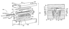
According to the illustrated embodiment, base 27 includes a cavity 275 for holding sealing member 25 and blocks 23, wherein each block 23, for example, formed from MP35N, Pt/IR, titanium or stainless steel, is mounted in a fixed position within base 27 and extends into a corresponding opening 251 of sealing member 25 such that a groove 230 of each block 23 further defines the perimeter of bore 21, and such that sealing member 25 extends around each block 23 within cavity 275. When cap 26 is brought alongside base 27, each resilient member 24 also extends into a corresponding opening 251 of sealing member 251, for example as is illustrated in FIG. 3A . According to preferred embodiments of the present invention, sealing member 25 is formed from an elastomeric insulative material, preferably silicone rubber, and is held in cavity 275, for example, via an interference fit, without additional securing means, for example, bonding; however the scope of the invention is not so limited, and additional securing means, for example, silicone or polyurethane adhesive, may be used to retain member 25 in cavity 275, according to alternate embodiments.
According to the illustrated embodiment, when cap 76 of assembly 70 is brought into engagement with base 77, each of resilient members 781 is inserted into the corresponding seal member opening 751 and each of resilient members 783 is inserted into the corresponding seal member opening 753 such that each member 781 is compressed between inner sidewall 701 of the corresponding block 721 and the corresponding connector element 741, and each member 783 is compressed between inner sidewall 703 of the corresponding block 723 and the corresponding connector element 743. Thus, when cap 76 is securely engages with base 77, a spring force of each resilient member 781, 783 causes relatively stable electrical coupling between the corresponding connector element 741, 743 and the corresponding sidewall 701, 703, via conductive surfaces of each corresponding resilient member 781, 783. These surfaces of members 781, 783, as well as sidewalls 701, 703, may include surface treatments to enhance conductivity, for example, gold sputtering or electroplating.
In the foregoing detailed description, the invention has been described with reference to specific embodiments. However, it may be appreciated that various modifications and changes can be made without departing from the scope of the invention as set forth in the appended claims.
Claims (40)
1. An electrical connection assembly for a medical device, the assembly comprising:
a module including a base for mounting to a housing of the medical device, a cap engagable with the base, and an area for receiving a medical electrical lead connector, the lead connector including a plurality of connector elements;
a plurality of rigid conductive sidewalls each mounted in a fixed position to the module base, each sidewall defining a portion of a perimeter of the area for receiving the lead connector;
a plurality of feedthrough wires each coupled to a corresponding sidewall of the plurality of rigid conductive sidewalls and each extending from the assembly for electrical coupling with circuitry contained within the housing of the medical device; and
a plurality of resilient members attached to the module cap, each member applying a spring force against a corresponding connector element of the plurality of connector elements, when the lead connector is received within the area, when each connector element of the plurality of connector elements is positioned adjacent to a corresponding conductive sidewall of the plurality of conductive sidewalls, and when the module cap is engaged with the module base;
wherein the applied spring force of each resilient member causes electrical coupling between the corresponding connector element and the corresponding conductive sidewall.
2. The assembly of claim 1 , wherein:
the plurality of connector elements comprises a first connector element and a second connector element, the first and second connector elements spaced apart from one another along a length of the lead connector; and
the plurality of rigid conductive sidewalls comprises a first sidewall and a second sidewall, the first and second sidewalls spaced apart from one another for alignment with the first and second connector elements, respectively, when the lead connector is received within the area.
3. The assembly of claim 1 , wherein:
the plurality of connector elements comprises a first connector element and a second connector element, the first and second connector elements spaced apart from one another on either side of a longitudinal axis of the lead connector; and
the plurality of rigid conductive sidewalls comprises a first sidewall and a second sidewall, the first and second sidewalls disposed opposite one another for alignment with the first and second connector elements, respectively, when the lead connector is received within the area.
4. The assembly of claim 1 , wherein the spring force of each resilient member urges the corresponding connector element into contact with the corresponding conductive sidewall to cause the electrical coupling.
5. The assembly of claim 1 , wherein each resilient member further includes a conductive surface and the spring force of each resilient member urges the conductive surface of the member into contact with the corresponding connector element and the corresponding conductive sidewall to cause the electrical coupling.
6. The assembly of claim 1 , wherein the module further includes a hinged coupling joining the module cap to the module base.
7. The assembly of claim 1 , further comprising a sealing member surrounding the plurality of conductive sidewalls and including at least one interior surface further defining the perimeter of the area for receiving the lead connector.
8. The assembly of claim 7 , wherein:
the sealing member further includes opposing outer tapered surfaces; and
the module base includes a cavity having opposing tapering sidewalls interfacing with the outer tapered surfaces of the sealing member.
9. The assembly of claim 7 , wherein the sealing member further includes a first portion attached to the module cap and surrounding the plurality of resilient members, and a second portion held in the module base.
10. The assembly of claim 9 , wherein:
the first and second portions of the sealing member each include opposing outer tapered surfaces; and
the module base includes a cavity having opposing tapering sidewalls interfacing with the outer tapered surfaces of the first and second portions of the sealing member.
11. A medical device, comprising:
a housing containing electronic circuitry;
a module including a base mounted to the housing, a cap engagable with the base, and an area for receiving a medical electrical lead connector, the lead connector including a plurality of connector elements;
a plurality of feedthrough wires each extending from the module and into the housing for electrical coupling with the circuitry contained therein;
a plurality of rigid conductive sidewalls each mounted in a fixed position to the module base, each defining a portion of a perimeter of the area for receiving the lead connector, and each being electrically coupled to a corresponding feedthrough wire of the plurality of feedthrough wires; and
a plurality of resilient members attached to the module cap, each member applying a spring force against a corresponding connector element of the plurality of connector elements, when the lead connector is received within the area, when each connector element of the plurality of connector elements is positioned adjacent to a corresponding conductive sidewall of the plurality of conductive sidewalls, and when the module cap is engaged with the module base;
wherein the applied spring force of each resilient member causes electrical coupling between the corresponding connector element and the corresponding conductive sidewall.
12. The device of claim 11 , wherein:
the plurality of connector elements comprises a first connector element and a second connector element, the first and second connector elements spaced apart from one another along a length of the lead connector; and
the plurality of rigid conductive sidewalls comprises a first sidewall and a second sidewall, the first and second sidewalls spaced apart from one another for alignment with the first and second connector elements, respectively, when the lead connector is received within the area.
13. The device of claim 11 , wherein:
the plurality of connector elements comprises a first connector element and a second connector element, the first and second connector elements spaced apart from one another on either side of a longitudinal axis of the lead connector; and
the plurality of rigid conductive sidewalls comprises a first sidewall and a second sidewall, the first and second sidewalls disposed opposite one another for alignment with the first and second connector elements, respectively, when the lead connector is received within the area.
14. The device of claim 11 , wherein the spring force of each resilient member urges the corresponding connector element into contact with the corresponding conductive sidewall to cause the electrical coupling.
15. The device of claim 11 , wherein each resilient member further includes a conductive surface and the spring force of each resilient member urges the conductive surface of the member into contact with the corresponding connector element and the corresponding conductive sidewall to cause the electrical coupling.
16. The device of claim 11 , wherein the module further includes a hinged coupling joining the module cap to the module base.
17. The device of claim 11 , further comprising a sealing member surrounding the plurality of conductive sidewalls and including at least one interior surface further defining the perimeter of the area for receiving the lead connector.
18. The device of claim 17 , wherein:
the sealing member further includes opposing outer tapered surfaces; and
the module base includes a cavity having opposing tapering sidewalls interfacing with the outer tapered surfaces of the sealing member.
19. The device of claim 17 , wherein the sealing member further includes a first portion attached to the module cap and surrounding the plurality of resilient members, and a second portion held in the module base.
20. The device of claim 19 , wherein:
the first and second portions of the sealing member each include opposing outer tapered surfaces; and
the module base includes a cavity having opposing tapering sidewalls interfacing with the outer tapered surfaces of the first and second portions of the sealing member.
21. A method for making an electrical connection between a connector of a medical electrical lead and a rigid conductive sidewall held fixed within a connector module of a medical device, the method comprising:
bringing a connector element of the lead connector into proximity with the rigid conductive sidewall; and
applying a spring force against the connector element, after bringing the element into proximity with the sidewall, by bringing a resilient member into contact with the connector element, the spring force causing electrical coupling between the connector element and the conductive sidewall.
22. The method of claim 21 , wherein bringing the connector element into proximity with the rigid conductive sidewall comprises inserting the lead connector axially into a bore of the connector module, wherein a portion of a perimeter of the bore is defined by the sidewall.
23. The method of claim 21 , wherein bringing the connector element into proximity with the rigid conductive sidewall comprises inserting the lead connector radially into an area of the connector module, wherein a portion of a perimeter of the area is defined by the sidewall.
24. The method of claim 21 , wherein bringing the resilient member into contact with the connector element comprises engaging a cap of the connector module with a base of the connector module, wherein the resilient member is attached to the cap.
25. The method of claim 21 , wherein the spring force applied to the connector element forces the connector element into contact with the rigid conductive sidewall to cause the electrical coupling.
26. The method of claim 21 , wherein the spring force applied to the connector element forces the resilient member into contact with the rigid conductive sidewall, to cause the electrical coupling.
27. An electrical connection assembly for a medical device, the assembly comprising:
a base for mounting to a housing of the device, the base including a cavity having opposing tapering sidewalls;
a cap engagable with the base;
an area for receiving a medical electrical lead connector, the lead connector including a plurality of connector elements;
a plurality of electrical contact surfaces held within the cavity, each contact surface of the plurality of contact surfaces defining a portion of a perimeter of the area for receiving the lead connector, and each contact surface located for electrical coupling with a corresponding connector element of the lead connector, when the lead connector is inserted within the area; and
a sealing member held within the base cavity and surrounding the plurality of electrical contact surfaces, the sealing member including at least one interior surface, forming another portion of the perimeter of the area for receiving the lead connector, and opposing outer tapered surfaces interfacing with the opposing tapering sidewalls of the cavity;
wherein, when the cap is engaged with the base, the at least one interior surface of the sealing member is compressed about the lead connector inserted within the area.
28. The assembly of claim 27 , wherein the at least one interior surface of the sealing member surrounds a bore, the bore forming a portion of the area for receiving the lead connector.
29. The assembly of claim 27 , wherein the sealing member further includes a plurality of openings, and each contact surface extends into a corresponding opening of the plurality of openings.
30. The assembly of claim 29 , wherein the plurality of contact surfaces are arranged in first and second columns, the first and second columns extending alongside one another.
31. The assembly of claim 29 , wherein the sealing member further includes at least one void, independent of the at least one interior surface and the plurality of openings of the sealing member, the at least one void providing compressible space in a bulk volume of the sealing member.
32. The assembly of claim 27 , further comprising another sealing member attached to the cap, the other sealing member including at least one interior surface further defining the area for receiving the lead connector and the other sealing member configured to mate with the sealing member held in the base cavity, when the cap is engaged with the base.
33. The assembly of claim 32 , wherein the other sealing member includes opposing outer tapered surfaces interfacing with the opposing tapering sidewalls of the cavity, when the cap is engaged with the base.
34. A medical device, comprising:
a housing containing electronic circuitry
a base mounted to the housing and including a cavity having opposing tapering sidewalls;
a cap engagable with the base;
an area for receiving a medical electrical lead connector, the lead connector including a plurality of connector elements;
a plurality of electrical contact surfaces held within the cavity, each contact surface of the plurality of contact surfaces defining a portion of a perimeter of the area for receiving the lead connector, and each contact surface located for electrical coupling with a corresponding connector element of the lead connector when the lead connector is inserted within the area;
a plurality of feedthrough wires each electrically coupled to a corresponding contact surface of the plurality of contact surfaces and extending through the base and into the housing for electrical coupling with the circuitry contained therein;
a sealing member held within the base cavity and surrounding the plurality of electrical contact surfaces, the sealing member including at least one interior surface forming another portion of the perimeter of the area for receiving the lead connector, and opposing outer tapered surfaces interfacing with the opposing tapering sidewalls of the cavity;
wherein, when the cap is engaged with the base, the at least one interior surface of the sealing member is compressed about the lead connector inserted within the area.
35. The device of claim 34 , wherein the at least one interior surface of the sealing member surrounds a bore, the bore forming a portion of the area for receiving the lead connector.
36. The device of claim 34 , wherein the sealing member further includes a plurality of openings, and each contact surface extends into a corresponding opening of the plurality of openings.
37. The device of claim 36 , wherein the plurality of contact surfaces are arranged in first and second columns, the first and second columns extending alongside one another.
38. The device of claim 36 , wherein the sealing member further includes at least one void, independent of the at least one interior surface and the plurality of openings of the sealing member, the at least one void providing compressible space in a bulk volume of the sealing member.
39. The device of claim 34 , further comprising another sealing member attached to the cap, the other sealing member including at least one interior surface further defining the area for receiving the lead connector, and the other sealing member configured to mate with the sealing member held in the base cavity, when the cap is engaged with the base.
40. The device of claim 39 , wherein the other sealing member includes opposing outer tapered surfaces interfacing with the opposing tapering sidewalls of the cavity, when the cap is engaged with the base.
Priority Applications (3)
| Application Number | Priority Date | Filing Date | Title |
|---|---|---|---|
| US11/689,531 US7402083B2 (en) | 2006-03-23 | 2007-03-22 | Medical electrical lead connection systems and methods |
| US12/140,877 US7553193B2 (en) | 2006-03-23 | 2008-06-17 | Medical electrical lead connection systems and methods |
| US12/482,033 US7798862B2 (en) | 2006-03-23 | 2009-06-10 | Medical electrical lead connection systems and methods |
Applications Claiming Priority (2)
| Application Number | Priority Date | Filing Date | Title |
|---|---|---|---|
| US78519406P | 2006-03-23 | 2006-03-23 | |
| US11/689,531 US7402083B2 (en) | 2006-03-23 | 2007-03-22 | Medical electrical lead connection systems and methods |
Related Child Applications (1)
| Application Number | Title | Priority Date | Filing Date |
|---|---|---|---|
| US12/140,877 Continuation US7553193B2 (en) | 2006-03-23 | 2008-06-17 | Medical electrical lead connection systems and methods |
Publications (2)
| Publication Number | Publication Date |
|---|---|
| US20080009192A1 US20080009192A1 (en) | 2008-01-10 |
| US7402083B2 true US7402083B2 (en) | 2008-07-22 |
Family
ID=38190656
Family Applications (3)
| Application Number | Title | Priority Date | Filing Date |
|---|---|---|---|
| US11/689,531 Active US7402083B2 (en) | 2006-03-23 | 2007-03-22 | Medical electrical lead connection systems and methods |
| US12/140,877 Active US7553193B2 (en) | 2006-03-23 | 2008-06-17 | Medical electrical lead connection systems and methods |
| US12/482,033 Active US7798862B2 (en) | 2006-03-23 | 2009-06-10 | Medical electrical lead connection systems and methods |
Family Applications After (2)
| Application Number | Title | Priority Date | Filing Date |
|---|---|---|---|
| US12/140,877 Active US7553193B2 (en) | 2006-03-23 | 2008-06-17 | Medical electrical lead connection systems and methods |
| US12/482,033 Active US7798862B2 (en) | 2006-03-23 | 2009-06-10 | Medical electrical lead connection systems and methods |
Country Status (5)
| Country | Link |
|---|---|
| US (3) | US7402083B2 (en) |
| EP (2) | EP2004287B1 (en) |
| AT (2) | ATE474622T1 (en) |
| DE (2) | DE602007007917D1 (en) |
| WO (2) | WO2007112268A1 (en) |
Cited By (37)
| Publication number | Priority date | Publication date | Assignee | Title |
|---|---|---|---|---|
| US20080248696A1 (en) * | 2006-03-23 | 2008-10-09 | Medtronic, Inc. | Medical electrical lead connection systems and methods |
| US20080248690A1 (en) * | 2007-04-06 | 2008-10-09 | Medtronic, Inc. | Connector and contact assemblies for medical devices |
| US20090004923A1 (en) * | 2007-06-28 | 2009-01-01 | Apple Inc. | Apparatus and methods for connecting two electrical devices together |
| US20100063555A1 (en) * | 2008-09-05 | 2010-03-11 | Medtronic, Inc. | Electrical contact for implantable medical device |
| US20100070012A1 (en) * | 2008-09-15 | 2010-03-18 | Boston Scientific Neuromodulation Corporation | Lead connection system for an implantable electrical stimulation system and methods for making and using the systems |
| US7736191B1 (en) * | 2008-05-27 | 2010-06-15 | Jerzy Roman Sochor | Implantable connector with protected contacts |
| US7798864B2 (en) | 2008-03-12 | 2010-09-21 | Boston Scientific Neuromodulation Corporation | Low-profile connector for a neurostimulation lead |
| US20100240253A1 (en) * | 2007-10-03 | 2010-09-23 | Medltronic Inc. | Connector Assemblies for Implantable Medical Electrical Systems |
| US20100304592A1 (en) * | 2007-10-02 | 2010-12-02 | Kast John E | Connector Assemblies and Contacts for Implantable Medical Electrical Systems |
| US20110257503A1 (en) * | 2010-04-14 | 2011-10-20 | Medtronic, Inc. | Neurological screening connector |
| US20120135624A1 (en) * | 2010-11-30 | 2012-05-31 | Ad-Tech Medical Instrument Corp. | Electrical Connector for an In-Body Multi-Contact Medical Electrode Device |
| US9203175B1 (en) * | 2013-01-24 | 2015-12-01 | Pmt Corporation | Inline connector assembly |
| US9403022B2 (en) | 2010-01-29 | 2016-08-02 | Medtronic, Inc. | Header assembly for implantable medical device |
| US20170014635A1 (en) * | 2015-07-16 | 2017-01-19 | Boston Scientific Neuromodulation Corporation | Systems and methods for making and using connector contact arrays for electrical stimulation systems |
| US9956394B2 (en) | 2015-09-10 | 2018-05-01 | Boston Scientific Neuromodulation Corporation | Connectors for electrical stimulation systems and methods of making and using |
| US20180214036A1 (en) * | 2012-06-28 | 2018-08-02 | Volcano Corporation | Side-loading connectors for use with intravascular devices and associated systems and methods |
| US10201713B2 (en) | 2016-06-20 | 2019-02-12 | Boston Scientific Neuromodulation Corporation | Threaded connector assembly and methods of making and using the same |
| US10307602B2 (en) | 2016-07-08 | 2019-06-04 | Boston Scientific Neuromodulation Corporation | Threaded connector assembly and methods of making and using the same |
| US10342983B2 (en) | 2016-01-14 | 2019-07-09 | Boston Scientific Neuromodulation Corporation | Systems and methods for making and using connector contact arrays for electrical stimulation systems |
| US20190231172A1 (en) * | 2018-01-29 | 2019-08-01 | Bard Access Systems, Inc. | Connection Systems And Methods Thereof For Establishing Electrical Connections Across A Sterile Field |
| US10543374B2 (en) | 2016-09-30 | 2020-01-28 | Boston Scientific Neuromodulation Corporation | Connector assemblies with bending limiters for electrical stimulation systems and methods of making and using same |
| US10576269B2 (en) | 2017-01-03 | 2020-03-03 | Boston Scientific Neuromodulation Corporation | Force-decoupled and strain relieving lead and methods of making and using |
| US10603499B2 (en) | 2017-04-07 | 2020-03-31 | Boston Scientific Neuromodulation Corporation | Tapered implantable lead and connector interface and methods of making and using |
| US10639485B2 (en) | 2017-09-15 | 2020-05-05 | Boston Scientific Neuromodulation Corporation | Actuatable lead connector for an operating room cable assembly and methods of making and using |
| US10814136B2 (en) | 2017-02-28 | 2020-10-27 | Boston Scientific Neuromodulation Corporation | Toolless connector for latching stimulation leads and methods of making and using |
| US10905871B2 (en) | 2017-01-27 | 2021-02-02 | Boston Scientific Neuromodulation Corporation | Lead assemblies with arrangements to confirm alignment between terminals and contacts |
| US10918873B2 (en) | 2017-07-25 | 2021-02-16 | Boston Scientific Neuromodulation Corporation | Systems and methods for making and using an enhanced connector of an electrical stimulation system |
| US11045656B2 (en) | 2017-09-15 | 2021-06-29 | Boston Scientific Neuromodulation Corporation | Biased lead connector for operating room cable assembly and methods of making and using |
| US11052259B2 (en) | 2018-05-11 | 2021-07-06 | Boston Scientific Neuromodulation Corporation | Connector assembly for an electrical stimulation system and methods of making and using |
| US11103712B2 (en) | 2018-01-16 | 2021-08-31 | Boston Scientific Neuromodulation Corporation | Connector assemblies with novel spacers for electrical stimulation systems and methods of making and using same |
| US11139603B2 (en) | 2017-10-03 | 2021-10-05 | Boston Scientific Neuromodulation Corporation | Connectors with spring contacts for electrical stimulation systems and methods of making and using same |
| US11167128B2 (en) | 2018-11-16 | 2021-11-09 | Boston Scientific Neuromodulation Corporation | Directional electrical stimulation leads, systems and methods for spinal cord stimulation |
| US11172959B2 (en) | 2018-05-02 | 2021-11-16 | Boston Scientific Neuromodulation Corporation | Long, flexible sheath and lead blank and systems and methods of making and using |
| US11304772B2 (en) | 2018-05-18 | 2022-04-19 | Bard Access Systems, Inc. | Connection systems and methods thereof for establishing an electrical connection through a drape |
| US11357992B2 (en) | 2019-05-03 | 2022-06-14 | Boston Scientific Neuromodulation Corporation | Connector assembly for an electrical stimulation system and methods of making and using |
| US11737848B2 (en) | 2019-07-29 | 2023-08-29 | Bard Access Systems, Inc. | Connection systems and methods for establishing optical and electrical connections through a drape |
| US11936132B2 (en) | 2018-01-29 | 2024-03-19 | Bard Access Systems, Inc. | Connection system for establishing an electrical connection through a drape and methods thereof |
Families Citing this family (23)
| Publication number | Priority date | Publication date | Assignee | Title |
|---|---|---|---|---|
| US8190259B1 (en) | 2007-04-10 | 2012-05-29 | Advanced Neuromodulation Systems, Inc. | Header design for implantable pulse generator |
| US7794256B1 (en) | 2007-08-09 | 2010-09-14 | Jerzy Roman Sochor | Implantable connector with contact-containing feedthrough pins |
| US8140163B1 (en) | 2008-05-23 | 2012-03-20 | Advanced Neuromodulation Systems, Inc. | Implantable pulse generator and method of use |
| US8364281B2 (en) * | 2008-11-07 | 2013-01-29 | W. L. Gore & Associates, Inc. | Implantable lead |
| US8996134B2 (en) | 2008-11-07 | 2015-03-31 | W. L. Gore & Associates, Inc. | Implantable lead |
| US10449373B2 (en) | 2009-07-31 | 2019-10-22 | Medtronic, Inc. | Connector enclosure assemblies of medical devices including an angled lead passageway |
| US9302092B2 (en) * | 2009-12-30 | 2016-04-05 | Cardiac Pacemakers, Inc. | Multi-function lead implant tool |
| US8706257B2 (en) | 2010-03-23 | 2014-04-22 | Advanced Neuromodulation Systems, Inc. | Connector design for implantable pulse generator for neurostimulation, implantable stimulation lead, and methods of fabrication |
| US9083129B2 (en) | 2010-07-14 | 2015-07-14 | Cardiac Pacemakers, Inc. | Multipolar lead evaluation device |
| WO2012067728A1 (en) | 2010-11-19 | 2012-05-24 | Cardiac Pacemakers, Inc. | Peel-away is-4/df-4 lead implant tool with electrical contacts |
| US9138587B2 (en) | 2010-12-28 | 2015-09-22 | Medtronic, Inc. | Medical devices including connector enclosures with a metallic weld to a can housing circuitry |
| US9144689B2 (en) | 2010-12-28 | 2015-09-29 | Medtronic, Inc. | Medical devices including metallic connector enclosures |
| US9138588B2 (en) | 2010-12-28 | 2015-09-22 | Medtronic, Inc. | Medical devices including connector enclosures with an integrated conductor feed-through |
| US9427565B2 (en) | 2012-11-07 | 2016-08-30 | The Florida International University Board Of Trustees | Modular multi-channel inline connector system |
| US9409009B2 (en) | 2012-11-07 | 2016-08-09 | The Florida International University | Multi-lead multi-electrode management system |
| CA2906736C (en) | 2013-03-15 | 2021-11-02 | Hni Technologies Inc. | Chair with activated back flex |
| US9166334B1 (en) * | 2014-04-11 | 2015-10-20 | Chicony Electronics Co., Ltd. | Slide connector, slide socket and electronic device for electrical connecting with slide connector |
| US10261786B2 (en) * | 2017-03-09 | 2019-04-16 | Google Llc | Vector processing unit |
| US9972951B1 (en) * | 2017-06-30 | 2018-05-15 | Benchmark Electronics, Inc. | Medical lead connectors with contact electrodes |
| US10608390B2 (en) * | 2017-06-30 | 2020-03-31 | Benchmark Electronics, Inc. | Medical lead connectors with contact electrodes |
| US10644468B2 (en) * | 2017-06-30 | 2020-05-05 | Benchmark Electronics, Inc. | Medical lead connectors with contact electrodes |
| US20230146724A1 (en) * | 2020-03-13 | 2023-05-11 | Spr Therapeutics, Inc. | Stimulation lead connection system |
| US11621515B2 (en) * | 2021-03-25 | 2023-04-04 | Neuropace, Inc. | Connector assembly for active implantable medical device |
Citations (13)
| Publication number | Priority date | Publication date | Assignee | Title |
|---|---|---|---|---|
| US4469104A (en) | 1982-07-16 | 1984-09-04 | Cordis Corporation | Multipolar connector for pacing lead |
| US4712557A (en) | 1986-04-28 | 1987-12-15 | Cordis Leads, Inc. | A pacer including a multiple connector assembly with removable wedge and method of use |
| US4869255A (en) | 1987-12-04 | 1989-09-26 | Ad-Tech Medical Instrument Corp. | Electrical connection device |
| US5354326A (en) | 1993-01-27 | 1994-10-11 | Medtronic, Inc. | Screening cable connector for interface to implanted lead |
| US5560358A (en) | 1994-09-08 | 1996-10-01 | Radionics, Inc. | Connector design for multi-contact medical electrode |
| US6162101A (en) | 1998-09-03 | 2000-12-19 | Pmt Corporation | Connector assembly for electrodes |
| US6321126B1 (en) | 1998-12-07 | 2001-11-20 | Advanced Bionics Corporation | Implantable connector |
| US6415168B1 (en) | 2000-04-19 | 2002-07-02 | Ad-Tech Medical Instrument Corporation | Electrical connector for multi-contact medical electrodes |
| US6575793B1 (en) * | 2001-12-26 | 2003-06-10 | Hon Hai Precision Ind. Co., Ltd. | Audio jack connector |
| US6662035B2 (en) | 2001-09-13 | 2003-12-09 | Neuropace, Inc. | Implantable lead connector assembly for implantable devices and methods of using it |
| US6725096B2 (en) | 2000-05-05 | 2004-04-20 | Advanced Bionics Corporation | Multiple in-line contact connector |
| US6741892B1 (en) | 2000-03-10 | 2004-05-25 | Advanced Bionics Corporation | Movable contact locking mechanism for spinal cord stimulator lead connector |
| US7134919B2 (en) | 2005-01-04 | 2006-11-14 | Ad-Tech Medical Instrument Corp. | Multiple-use, stimulation-accommodating connector |
Family Cites Families (6)
| Publication number | Priority date | Publication date | Assignee | Title |
|---|---|---|---|---|
| US5046242A (en) * | 1982-07-27 | 1991-09-10 | Commonwealth Of Australia | Method of making feedthrough assemblies having hermetic seals between electrical feedthrough elements and ceramic carriers therefor |
| US4715380A (en) * | 1986-04-03 | 1987-12-29 | Telectronics N.V. | Capped pacer neck containing a connector assembly |
| US5947761A (en) * | 1998-09-29 | 1999-09-07 | The Whitaker Corporation | Electrical connector with pivoting wire fixture |
| US6671534B2 (en) * | 2000-04-19 | 2003-12-30 | Ad-Tech Medical Instrument Corporation | Electrical connector for multi-contact medical electrodes |
| DE602007007917D1 (en) * | 2006-03-23 | 2010-09-02 | Medtronic Inc | SYSTEMS AND METHOD FOR CONNECTING MEDICAL ELECTRODES |
| US7425142B1 (en) * | 2007-03-16 | 2008-09-16 | Ad-Tech Medical Instrument Corp. | Electrical connector for an in-body multi-contact medical electrode device |
-
2007
- 2007-03-22 DE DE602007007917T patent/DE602007007917D1/en active Active
- 2007-03-22 AT AT07759134T patent/ATE474622T1/en not_active IP Right Cessation
- 2007-03-22 EP EP07759134A patent/EP2004287B1/en not_active Not-in-force
- 2007-03-22 WO PCT/US2007/064655 patent/WO2007112268A1/en active Application Filing
- 2007-03-22 AT AT07759139T patent/ATE485078T1/en not_active IP Right Cessation
- 2007-03-22 US US11/689,531 patent/US7402083B2/en active Active
- 2007-03-22 DE DE602007009952T patent/DE602007009952D1/en active Active
- 2007-03-22 EP EP07759139A patent/EP2004288B1/en not_active Not-in-force
- 2007-03-22 WO PCT/US2007/064660 patent/WO2007109762A1/en active Application Filing
-
2008
- 2008-06-17 US US12/140,877 patent/US7553193B2/en active Active
-
2009
- 2009-06-10 US US12/482,033 patent/US7798862B2/en active Active
Patent Citations (13)
| Publication number | Priority date | Publication date | Assignee | Title |
|---|---|---|---|---|
| US4469104A (en) | 1982-07-16 | 1984-09-04 | Cordis Corporation | Multipolar connector for pacing lead |
| US4712557A (en) | 1986-04-28 | 1987-12-15 | Cordis Leads, Inc. | A pacer including a multiple connector assembly with removable wedge and method of use |
| US4869255A (en) | 1987-12-04 | 1989-09-26 | Ad-Tech Medical Instrument Corp. | Electrical connection device |
| US5354326A (en) | 1993-01-27 | 1994-10-11 | Medtronic, Inc. | Screening cable connector for interface to implanted lead |
| US5560358A (en) | 1994-09-08 | 1996-10-01 | Radionics, Inc. | Connector design for multi-contact medical electrode |
| US6162101A (en) | 1998-09-03 | 2000-12-19 | Pmt Corporation | Connector assembly for electrodes |
| US6321126B1 (en) | 1998-12-07 | 2001-11-20 | Advanced Bionics Corporation | Implantable connector |
| US6741892B1 (en) | 2000-03-10 | 2004-05-25 | Advanced Bionics Corporation | Movable contact locking mechanism for spinal cord stimulator lead connector |
| US6415168B1 (en) | 2000-04-19 | 2002-07-02 | Ad-Tech Medical Instrument Corporation | Electrical connector for multi-contact medical electrodes |
| US6725096B2 (en) | 2000-05-05 | 2004-04-20 | Advanced Bionics Corporation | Multiple in-line contact connector |
| US6662035B2 (en) | 2001-09-13 | 2003-12-09 | Neuropace, Inc. | Implantable lead connector assembly for implantable devices and methods of using it |
| US6575793B1 (en) * | 2001-12-26 | 2003-06-10 | Hon Hai Precision Ind. Co., Ltd. | Audio jack connector |
| US7134919B2 (en) | 2005-01-04 | 2006-11-14 | Ad-Tech Medical Instrument Corp. | Multiple-use, stimulation-accommodating connector |
Cited By (64)
| Publication number | Priority date | Publication date | Assignee | Title |
|---|---|---|---|---|
| US7798862B2 (en) | 2006-03-23 | 2010-09-21 | Medtronic, Inc. | Medical electrical lead connection systems and methods |
| US7553193B2 (en) * | 2006-03-23 | 2009-06-30 | Medtronic, Inc. | Medical electrical lead connection systems and methods |
| US20090247018A1 (en) * | 2006-03-23 | 2009-10-01 | Medtronic, Inc. | Medical electrical lead connection systems and methods |
| US20080248696A1 (en) * | 2006-03-23 | 2008-10-09 | Medtronic, Inc. | Medical electrical lead connection systems and methods |
| US20080248690A1 (en) * | 2007-04-06 | 2008-10-09 | Medtronic, Inc. | Connector and contact assemblies for medical devices |
| US8250752B2 (en) | 2007-04-06 | 2012-08-28 | Medtronic, Inc. | Method of assembling a connector assembly for a medical device |
| US7510447B2 (en) * | 2007-04-06 | 2009-03-31 | Medtronic, Inc. | Connector and contact assemblies for medical devices |
| US20090144973A1 (en) * | 2007-04-06 | 2009-06-11 | Medtronic, Inc. | Connector and contact assemblies for medical devices |
| US8182293B2 (en) | 2007-06-28 | 2012-05-22 | Apple Inc. | Apparatus and methods for connecting two electrical devices together |
| US7780478B2 (en) * | 2007-06-28 | 2010-08-24 | Apple Inc. | Apparatus and methods for connecting two electrical devices together |
| US20090004923A1 (en) * | 2007-06-28 | 2009-01-01 | Apple Inc. | Apparatus and methods for connecting two electrical devices together |
| US20100273356A1 (en) * | 2007-06-28 | 2010-10-28 | Apple Inc. | Apparatus and methods for connecting two electrical devices together |
| US8123567B2 (en) | 2007-10-02 | 2012-02-28 | Medtronic, Inc. | Connector assemblies and contacts for implantable medical electrical systems |
| US20100304592A1 (en) * | 2007-10-02 | 2010-12-02 | Kast John E | Connector Assemblies and Contacts for Implantable Medical Electrical Systems |
| US8206180B1 (en) | 2007-10-02 | 2012-06-26 | Medtronic Inc. | Connector assemblies and contacts for implantable medical electrical systems |
| US8412330B2 (en) | 2007-10-03 | 2013-04-02 | Medtronic, Inc. | Connector assemblies for implantable medical electrical systems |
| US20100240253A1 (en) * | 2007-10-03 | 2010-09-23 | Medltronic Inc. | Connector Assemblies for Implantable Medical Electrical Systems |
| US7798864B2 (en) | 2008-03-12 | 2010-09-21 | Boston Scientific Neuromodulation Corporation | Low-profile connector for a neurostimulation lead |
| US7736191B1 (en) * | 2008-05-27 | 2010-06-15 | Jerzy Roman Sochor | Implantable connector with protected contacts |
| US9095728B2 (en) | 2008-09-05 | 2015-08-04 | Medtronic, Inc. | Electrical contact for implantable medical device |
| US20100063555A1 (en) * | 2008-09-05 | 2010-03-11 | Medtronic, Inc. | Electrical contact for implantable medical device |
| US9687660B2 (en) | 2008-09-05 | 2017-06-27 | Medtronic, Inc. | Electrical contact for implantable medical device |
| US10632316B2 (en) | 2008-09-05 | 2020-04-28 | Medtronic, Inc. | Electrical contact for implantable medical device |
| US11154721B2 (en) | 2008-09-05 | 2021-10-26 | Medtronic, Inc. | Method of forming an electrical contact for implantable medical device |
| US8548601B2 (en) * | 2008-09-15 | 2013-10-01 | Boston Scientific Neuromodulation Corporation | Lead connection system for an implantable electrical stimulation system and methods for making and using the systems |
| US8666510B2 (en) | 2008-09-15 | 2014-03-04 | Boston Scientific Neuromodulation Corporation | Lead connection system for an implantable electrical stimulation system and methods for making and using the systems |
| US20100070012A1 (en) * | 2008-09-15 | 2010-03-18 | Boston Scientific Neuromodulation Corporation | Lead connection system for an implantable electrical stimulation system and methods for making and using the systems |
| US9403022B2 (en) | 2010-01-29 | 2016-08-02 | Medtronic, Inc. | Header assembly for implantable medical device |
| US9655534B2 (en) * | 2010-04-14 | 2017-05-23 | Medtronic, Inc. | Neurological screening connector |
| US20110257503A1 (en) * | 2010-04-14 | 2011-10-20 | Medtronic, Inc. | Neurological screening connector |
| US10165957B2 (en) | 2010-04-14 | 2019-01-01 | Medtronic, Inc. | Neurological screening connector |
| US8439714B2 (en) * | 2010-11-30 | 2013-05-14 | Ad-Tech Medical Instrument Corp. | Electrical connector for an in-body multi-contact medical electrode device |
| US20120135624A1 (en) * | 2010-11-30 | 2012-05-31 | Ad-Tech Medical Instrument Corp. | Electrical Connector for an In-Body Multi-Contact Medical Electrode Device |
| US20180214036A1 (en) * | 2012-06-28 | 2018-08-02 | Volcano Corporation | Side-loading connectors for use with intravascular devices and associated systems and methods |
| US9203175B1 (en) * | 2013-01-24 | 2015-12-01 | Pmt Corporation | Inline connector assembly |
| US9656093B2 (en) * | 2015-07-16 | 2017-05-23 | Boston Scientific Neuromodulation Corporation | Systems and methods for making and using connector contact arrays for electrical stimulation systems |
| US20170216604A1 (en) * | 2015-07-16 | 2017-08-03 | Boston Scientific Neuromodulation Corporation | Systems and methods for making and using connector contact arrays for electrical stimulation systems |
| US9839787B2 (en) * | 2015-07-16 | 2017-12-12 | Boston Scientific Neuromodulation Corporation | Systems and methods for making and using connector contact arrays for electrical stimulation systems |
| US20170014635A1 (en) * | 2015-07-16 | 2017-01-19 | Boston Scientific Neuromodulation Corporation | Systems and methods for making and using connector contact arrays for electrical stimulation systems |
| US9956394B2 (en) | 2015-09-10 | 2018-05-01 | Boston Scientific Neuromodulation Corporation | Connectors for electrical stimulation systems and methods of making and using |
| US10342983B2 (en) | 2016-01-14 | 2019-07-09 | Boston Scientific Neuromodulation Corporation | Systems and methods for making and using connector contact arrays for electrical stimulation systems |
| US10201713B2 (en) | 2016-06-20 | 2019-02-12 | Boston Scientific Neuromodulation Corporation | Threaded connector assembly and methods of making and using the same |
| US10307602B2 (en) | 2016-07-08 | 2019-06-04 | Boston Scientific Neuromodulation Corporation | Threaded connector assembly and methods of making and using the same |
| US10543374B2 (en) | 2016-09-30 | 2020-01-28 | Boston Scientific Neuromodulation Corporation | Connector assemblies with bending limiters for electrical stimulation systems and methods of making and using same |
| US10576269B2 (en) | 2017-01-03 | 2020-03-03 | Boston Scientific Neuromodulation Corporation | Force-decoupled and strain relieving lead and methods of making and using |
| US10905871B2 (en) | 2017-01-27 | 2021-02-02 | Boston Scientific Neuromodulation Corporation | Lead assemblies with arrangements to confirm alignment between terminals and contacts |
| US10814136B2 (en) | 2017-02-28 | 2020-10-27 | Boston Scientific Neuromodulation Corporation | Toolless connector for latching stimulation leads and methods of making and using |
| US10603499B2 (en) | 2017-04-07 | 2020-03-31 | Boston Scientific Neuromodulation Corporation | Tapered implantable lead and connector interface and methods of making and using |
| US10918873B2 (en) | 2017-07-25 | 2021-02-16 | Boston Scientific Neuromodulation Corporation | Systems and methods for making and using an enhanced connector of an electrical stimulation system |
| US11045656B2 (en) | 2017-09-15 | 2021-06-29 | Boston Scientific Neuromodulation Corporation | Biased lead connector for operating room cable assembly and methods of making and using |
| US10639485B2 (en) | 2017-09-15 | 2020-05-05 | Boston Scientific Neuromodulation Corporation | Actuatable lead connector for an operating room cable assembly and methods of making and using |
| US11951317B2 (en) | 2017-09-15 | 2024-04-09 | Boston Scientific Neuromodulation Corporation | Biased lead connector for operating room cable assembly and methods of making and using |
| US11139603B2 (en) | 2017-10-03 | 2021-10-05 | Boston Scientific Neuromodulation Corporation | Connectors with spring contacts for electrical stimulation systems and methods of making and using same |
| US11103712B2 (en) | 2018-01-16 | 2021-08-31 | Boston Scientific Neuromodulation Corporation | Connector assemblies with novel spacers for electrical stimulation systems and methods of making and using same |
| US20190231172A1 (en) * | 2018-01-29 | 2019-08-01 | Bard Access Systems, Inc. | Connection Systems And Methods Thereof For Establishing Electrical Connections Across A Sterile Field |
| US11936132B2 (en) | 2018-01-29 | 2024-03-19 | Bard Access Systems, Inc. | Connection system for establishing an electrical connection through a drape and methods thereof |
| US11172959B2 (en) | 2018-05-02 | 2021-11-16 | Boston Scientific Neuromodulation Corporation | Long, flexible sheath and lead blank and systems and methods of making and using |
| US11052259B2 (en) | 2018-05-11 | 2021-07-06 | Boston Scientific Neuromodulation Corporation | Connector assembly for an electrical stimulation system and methods of making and using |
| US11304772B2 (en) | 2018-05-18 | 2022-04-19 | Bard Access Systems, Inc. | Connection systems and methods thereof for establishing an electrical connection through a drape |
| US11628030B2 (en) | 2018-05-18 | 2023-04-18 | Bard Access Systems, Inc. | Connection systems and methods thereof for establishing an electrical connection through a drape |
| US11167128B2 (en) | 2018-11-16 | 2021-11-09 | Boston Scientific Neuromodulation Corporation | Directional electrical stimulation leads, systems and methods for spinal cord stimulation |
| US11357992B2 (en) | 2019-05-03 | 2022-06-14 | Boston Scientific Neuromodulation Corporation | Connector assembly for an electrical stimulation system and methods of making and using |
| US11612755B2 (en) | 2019-05-03 | 2023-03-28 | Boston Scientific Neuromodulation Corporation | Connector assembly for an electrical stimulation system and methods of making and using |
| US11737848B2 (en) | 2019-07-29 | 2023-08-29 | Bard Access Systems, Inc. | Connection systems and methods for establishing optical and electrical connections through a drape |
Also Published As
| Publication number | Publication date |
|---|---|
| US7798862B2 (en) | 2010-09-21 |
| EP2004288A1 (en) | 2008-12-24 |
| WO2007112268A1 (en) | 2007-10-04 |
| EP2004287B1 (en) | 2010-07-21 |
| ATE485078T1 (en) | 2010-11-15 |
| DE602007009952D1 (en) | 2010-12-02 |
| US20090247018A1 (en) | 2009-10-01 |
| US20080248696A1 (en) | 2008-10-09 |
| ATE474622T1 (en) | 2010-08-15 |
| WO2007109762A1 (en) | 2007-09-27 |
| WO2007109762A8 (en) | 2008-03-13 |
| EP2004288B1 (en) | 2010-10-20 |
| US20080009192A1 (en) | 2008-01-10 |
| US7553193B2 (en) | 2009-06-30 |
| DE602007007917D1 (en) | 2010-09-02 |
| EP2004287A1 (en) | 2008-12-24 |
Similar Documents
| Publication | Publication Date | Title |
|---|---|---|
| US7402083B2 (en) | Medical electrical lead connection systems and methods | |
| US8206180B1 (en) | Connector assemblies and contacts for implantable medical electrical systems | |
| US8412330B2 (en) | Connector assemblies for implantable medical electrical systems | |
| EP1663390B1 (en) | Implantable medical lead connector sleeves | |
| US8250752B2 (en) | Method of assembling a connector assembly for a medical device | |
| US6198969B1 (en) | Implantable connector for multi-output neurostimulators | |
| EP2461867B1 (en) | Connector and contact assemblies for medical devices | |
| US6609029B1 (en) | Clip lock mechanism for retaining lead | |
| US7303422B2 (en) | Implantable modular, multi-channel connector system for nerve signal sensing and electrical stimulation applications | |
| US7860568B2 (en) | Lead retention assembly for implantable medical device | |
| US7537474B2 (en) | Lead receptacle and pin frame assembly | |
| US20120283806A1 (en) | Hyperboloid electrical connector assembly | |
| US20230127724A1 (en) | Implantable medical devices having modular lead bores | |
| US7305267B2 (en) | Connector module having reduced insertion force | |
| US6390843B1 (en) | Lead lock for implantable medical device | |
| EP3045202B1 (en) | Lead lock for securing a lead to a pulse generator | |
| CN101175528A (en) | Medical electronics electrical implantable medical devices |
Legal Events
| Date | Code | Title | Description |
|---|---|---|---|
| AS | Assignment |
Owner name: MEDTRONIC, INC., MINNESOTA Free format text: ASSIGNMENT OF ASSIGNORS INTEREST;ASSIGNORS:KAST, JOHN;LENT, MARK;OLSEN, JIM;AND OTHERS;REEL/FRAME:019104/0146;SIGNING DATES FROM 20070328 TO 20070329 |
|
| STCF | Information on status: patent grant |
Free format text: PATENTED CASE |
|
| FPAY | Fee payment |
Year of fee payment: 4 |
|
| FPAY | Fee payment |
Year of fee payment: 8 |
|
| MAFP | Maintenance fee payment |
Free format text: PAYMENT OF MAINTENANCE FEE, 12TH YEAR, LARGE ENTITY (ORIGINAL EVENT CODE: M1553); ENTITY STATUS OF PATENT OWNER: LARGE ENTITY Year of fee payment: 12 |