US7404567B2 - Active wheelchair - Google Patents

Active wheelchair Download PDF

Info

Publication number
US7404567B2
US7404567B2 US10/549,924 US54992404A US7404567B2 US 7404567 B2 US7404567 B2 US 7404567B2 US 54992404 A US54992404 A US 54992404A US 7404567 B2 US7404567 B2 US 7404567B2
Authority
US
United States
Prior art keywords
wheelchair
seat
aperture
frame
width
Prior art date
Legal status (The legal status is an assumption and is not a legal conclusion. Google has not performed a legal analysis and makes no representation as to the accuracy of the status listed.)
Expired - Fee Related, expires
Application number
US10/549,924
Other versions
US20060181051A1 (en
Inventor
Flemming Møller
Current Assignee (The listed assignees may be inaccurate. Google has not performed a legal analysis and makes no representation or warranty as to the accuracy of the list.)
R82 AS
Original Assignee
R82 AS
Priority date (The priority date is an assumption and is not a legal conclusion. Google has not performed a legal analysis and makes no representation as to the accuracy of the date listed.)
Filing date
Publication date
Application filed by R82 AS filed Critical R82 AS
Assigned to R82 A/S reassignment R82 A/S ASSIGNMENT OF ASSIGNORS INTEREST (SEE DOCUMENT FOR DETAILS). Assignors: MOLLER, FLEMMING
Publication of US20060181051A1 publication Critical patent/US20060181051A1/en
Application granted granted Critical
Publication of US7404567B2 publication Critical patent/US7404567B2/en
Expired - Fee Related legal-status Critical Current
Adjusted expiration legal-status Critical

Links

Images

Classifications

    • AHUMAN NECESSITIES
    • A61MEDICAL OR VETERINARY SCIENCE; HYGIENE
    • A61GTRANSPORT, PERSONAL CONVEYANCES, OR ACCOMMODATION SPECIALLY ADAPTED FOR PATIENTS OR DISABLED PERSONS; OPERATING TABLES OR CHAIRS; CHAIRS FOR DENTISTRY; FUNERAL DEVICES
    • A61G5/00Chairs or personal conveyances specially adapted for patients or disabled persons, e.g. wheelchairs
    • A61G5/10Parts, details or accessories
    • A61G5/12Rests specially adapted therefor, e.g. for the head or the feet
    • AHUMAN NECESSITIES
    • A61MEDICAL OR VETERINARY SCIENCE; HYGIENE
    • A61GTRANSPORT, PERSONAL CONVEYANCES, OR ACCOMMODATION SPECIALLY ADAPTED FOR PATIENTS OR DISABLED PERSONS; OPERATING TABLES OR CHAIRS; CHAIRS FOR DENTISTRY; FUNERAL DEVICES
    • A61G5/00Chairs or personal conveyances specially adapted for patients or disabled persons, e.g. wheelchairs
    • A61G5/10Parts, details or accessories
    • A61G5/1054Large wheels, e.g. higher than the seat portion
    • AHUMAN NECESSITIES
    • A61MEDICAL OR VETERINARY SCIENCE; HYGIENE
    • A61GTRANSPORT, PERSONAL CONVEYANCES, OR ACCOMMODATION SPECIALLY ADAPTED FOR PATIENTS OR DISABLED PERSONS; OPERATING TABLES OR CHAIRS; CHAIRS FOR DENTISTRY; FUNERAL DEVICES
    • A61G5/00Chairs or personal conveyances specially adapted for patients or disabled persons, e.g. wheelchairs
    • A61G5/10Parts, details or accessories
    • A61G5/12Rests specially adapted therefor, e.g. for the head or the feet
    • A61G5/128Rests specially adapted therefor, e.g. for the head or the feet for feet
    • AHUMAN NECESSITIES
    • A61MEDICAL OR VETERINARY SCIENCE; HYGIENE
    • A61GTRANSPORT, PERSONAL CONVEYANCES, OR ACCOMMODATION SPECIALLY ADAPTED FOR PATIENTS OR DISABLED PERSONS; OPERATING TABLES OR CHAIRS; CHAIRS FOR DENTISTRY; FUNERAL DEVICES
    • A61G2200/00Information related to the kind of patient or his position
    • A61G2200/10Type of patient
    • A61G2200/14Children
    • AHUMAN NECESSITIES
    • A61MEDICAL OR VETERINARY SCIENCE; HYGIENE
    • A61GTRANSPORT, PERSONAL CONVEYANCES, OR ACCOMMODATION SPECIALLY ADAPTED FOR PATIENTS OR DISABLED PERSONS; OPERATING TABLES OR CHAIRS; CHAIRS FOR DENTISTRY; FUNERAL DEVICES
    • A61G5/00Chairs or personal conveyances specially adapted for patients or disabled persons, e.g. wheelchairs
    • A61G5/10Parts, details or accessories
    • A61G5/1056Arrangements for adjusting the seat
    • A61G5/1059Arrangements for adjusting the seat adjusting the height of the seat
    • AHUMAN NECESSITIES
    • A61MEDICAL OR VETERINARY SCIENCE; HYGIENE
    • A61GTRANSPORT, PERSONAL CONVEYANCES, OR ACCOMMODATION SPECIALLY ADAPTED FOR PATIENTS OR DISABLED PERSONS; OPERATING TABLES OR CHAIRS; CHAIRS FOR DENTISTRY; FUNERAL DEVICES
    • A61G5/00Chairs or personal conveyances specially adapted for patients or disabled persons, e.g. wheelchairs
    • A61G5/10Parts, details or accessories
    • A61G5/1056Arrangements for adjusting the seat
    • A61G5/1062Arrangements for adjusting the seat adjusting the width of the seat
    • AHUMAN NECESSITIES
    • A61MEDICAL OR VETERINARY SCIENCE; HYGIENE
    • A61GTRANSPORT, PERSONAL CONVEYANCES, OR ACCOMMODATION SPECIALLY ADAPTED FOR PATIENTS OR DISABLED PERSONS; OPERATING TABLES OR CHAIRS; CHAIRS FOR DENTISTRY; FUNERAL DEVICES
    • A61G5/00Chairs or personal conveyances specially adapted for patients or disabled persons, e.g. wheelchairs
    • A61G5/10Parts, details or accessories
    • A61G5/1056Arrangements for adjusting the seat
    • A61G5/1075Arrangements for adjusting the seat tilting the whole seat backwards

Definitions

  • the present invention relates to the art of personal mobility vehicles, particularly vehicles for the physically impaired. Particular application is found in children's wheelchairs which will have to be adaptable as the child grows. However, it is to be appreciated that the present invention may also be applicable to wheelchairs for adults and may be utilized to custom fit wheelchairs to adults, may enable the chair to be utilized by adults or children of different sizes, or may be applicable to other vehicles.
  • U.S. Pat. No. 5,320,373 Robot et al.
  • two substantially rigged side frames are provided in order to fasten the front and rear wheels in either side.
  • the distance between the wheels in the driving direction of the wheelchair is not adjustable.
  • the point of gravity may be adjusted by mounting the seat in different positions in relation to the rigged frame holding the two wheel axles.
  • the tilt of the seat is adjusted by further displacing the two bearing arms arranged in each rigged side frame such that the tilting of the seat cannot be carried out stepless or while a person is seated in the chair.
  • transfer of the point of gravity in relation to the driving direction is not possible since the distance between the wheels is fixed whereby the chair has a firm wheel base.
  • a wheelchair comprising a seat, a back support, and a number of wheels wherein that said wheelchair comprising means for adjusting the width of the seat means for adjusting the width of the back support and means for adjusting the width of the track of the wheels.
  • the wheelchair according to the present invention can be accommodated to a person changing size or to persons having various sizes.
  • the user is provided with a comfortable seat and a wheelchair which does not have an unnecessary big width of the track of the wheels and do not extend unnecessarily in the forward direction. Because the width of the track of the wheels can be adapted to the user the wheelchair is easy to manoeuvre. Furthermore, it is easy to pull up to tables and desks because of the reduced forward extension.
  • the means for adjusting the width of the track of the wheels comprises a frame comprising a pair of back apertures, a pair of front apertures, and a central front aperture, each back aperture is adapted for receiving a variable length of a back spacer, each front aperture is adapted for receiving a variable length of a front spacer, said back spacer connected to a displacer connected to a back wheel, said displacer comprising an oval aperture adapted for interlocking a leg member, said leg member being connected to said front spacer, said leg member being connected to a front wheel, said central front aperture being an oval aperture adapted for interlocking a central leg member being connected to a wheel.
  • the frame is the central component of the wheelchair's substructure.
  • the apertures By providing the apertures, it is possible to arrange the wheels in the apertures such that this arrangement may be constructed in an adjustable manner.
  • the frame constituting the central part of the substructure of the wheelchair basically has a substantially triangular shape.
  • the pointed end of the triangle is pointing forwards and the base of the triangle is pointing backwards.
  • the wheel construction comprises for example the back wheel which by means of a displacer connects the axle of the back wheel to the back spacer.
  • the displacer is hereby a connection member such that the elevation of the frame may be altered by using different size displacers.
  • the displacers are generally arranged vertically in relation to the ground such that the distance from the frame to the wheels axles may be varied.
  • three apertures are also provided namely a pair of apertures having openings perpendicular to the intended travelling direction as well as an aperture opening in the front travelling direction.
  • the pair of apertures opening up in a direction perpendicular to the travelling direction may accommodate a pair of front spacers.
  • the front spacers are used when the wheelchair is used in its four-wheel configuration.
  • a leg member in either side of the frame is arranged adjacent the back apertures and extending forwards. From the two apertures arranged in the front end of the spacer, there are front spacers engaging the leg members in order to stabilise these and transfer the load to the central frame.
  • the leg members are in this manner fastened in apertures adjacent the two back apertures in the frame where means are provided for interlocking the leg members to the frame.
  • a front wheel is provided in the front end of each leg member.
  • the front aperture is used in the three-wheel configuration of the wheelchair according to the invention.
  • the leg members and front spacers as described above are replaced by a single central leg member extending from the frame member and forwards in the driving direction.
  • a front wheel is arranged at a distal end of the central leg member.
  • central frame member comprising the five apertures as described above to be able to configure the wheelchair both in the traditional four wheel configuration but also in a more easily manoeuvrable three wheel configuration.
  • both the back spacers and the front spacers are such that a variable length of these spacers may be inserted through the apertures and into the frame such that the wheel base in the distance between the front and the back wheels, the distance between the single front wheel and the back wheel may be varied according to the needs of the user.
  • the central frame thereby makes it possible for a user to both configure the wheelchair in the three or four wheel configuration and/or also the size of the wheelchair altogether such that it may fit to a person through a growth period or may be adapted to fit different size persons.
  • the apertures for receiving the leg members may be made as oval apertures as the leg members also advantageously may be made as members having an oval cross-section.
  • the moment of inertia is larger for such profiles such that it is possible to optimize the design and make a lighter construction by using the material characteristics in combination with providing a lightweight design and in this manner take advantage of the bigger moment of inertia due to a longer size in comparison to the smaller size of the rectangular or oval cross-section.
  • the means for interlocking the leg members and/or fixing the spacers both the back and front spacers in the frame and thereby the overall size of the wheelchair may be made in any suitable way, but in one advantageous embodiment, a slit is provided in the frame parallel to the insertion direction of the spacers.
  • a slit is provided in the frame parallel to the insertion direction of the spacers.
  • the wheelchair according to this embodiment of the invention provides a way of easily changing the width of the track of the wheels of the wheelchair. Because the width of the track of the back wheels relates to the length of the back spacer and the width of the track of the front wheels relates to the length of the front spacer the width of the track of the wheels can be easily changed by changing the length of the spacers or changing the amount of the length of the spacers received by the front and back apertures.
  • the spacers i.e. both the back spacers and the front spacers
  • a clamping collar is arranged, preferably integral with the apertures.
  • the clamping collar integral with the apertures can for example be shaped by providing a slit in the aperture parallel to the insertion direction of the back spacers. Across the slit bolts can be inserted such that by tightening the bolts, the material on either side of the slit will be forced together and thereby clamp and lock the back spacer into firm engagement and thereby prevent sliding of the back spacer in the aperture.
  • this embodiment provides the opportunity for using the same wheelchair in two very different setups.
  • each back aperture and front aperture are connected to a leg member the wheelchair is set up with four wheels and provides a very stable and classic look of the chair.
  • the wheelchair is provided with three wheels.
  • This three wheel setup provides a more sporty and easily manoeuvrable wheelchair.
  • the means for adjusting the width of the seat comprises two support members slidingly arranged in a seat plate.
  • the seat is fully adjustable and can be accommodated to the actual size of the user. It is advantageous that there is at least one support member on each side of the seat, and the seat can be supported by several slidingly arranged support members.
  • the wheelchair comprises at least one foot rest attached to said wheelchair with releasable attachment means, said releasable attachment means comprising a hook-shaped member pivotally secured to said wheelchair for engagement with a hook-shaped member on said foot rest.
  • the front single aperture can be used in order to insert a second type of foot rest.
  • a pipe member By inserting for example a pipe member into the aperture and locking it as disclosed above, this pipe member will have a very firm engagement with the wheelchair.
  • Plate-shaped foot rests having articulated connection to a beam member which again is articulately connected to the pipe member thereby provide for a multitude of adjustment possibilities in order to accommodate the user of the wheelchair.
  • the foot rest By further providing different fastening possibilities along the length of the pipe member, the foot rest can be adjusted to different leg lengths or differences in leg lengths of the individual user.
  • the fastening means can for example be in the shape of a bolt going trough a connection hub arranged at the opposite end of the foot plate member in the beam member. The bolt member can go straight through the pipe member and be tightened by a nut on the opposite side. In this manner a very simple but efficient assembly is provided.
  • the means for adjusting the width of the back support comprises a back frame comprising at least one track or aperture, a bracket comprising at least one aperture, at least one of the apertures and tracks respectively being elongated, at least one fastener penetrating at least one aperture of the back frame and one aperture of the bracket, said fastener securing the back frame to the bracket.
  • the width of the back support can be easily changed by loosening the fasteners. When the correct width of the back support is reached the fasteners can be fastened again.
  • a back frame with a totally different width can be used if the width of the back support has to be changed to a very different size.
  • the wheelchair further comprises means for tilting the seat and for maintaining an essential constant centre of gravity, said means comprising lockable adjustment means, a first and a second hinge member, both hinge members pivotally connected to said frame, and pivotally connected to said seat, seat adjustment means pivotally connected to said first hinge member and to said seat, said adjustment means comprises locking means.
  • the lockable adjustment means may be chosen from a blocking gas damper, an electrical actuator, a rack and a pinion electrically operated by means of a step motor, a spindle axle, or any other similar means.
  • the seat can be tilted, since the users can have different preferences about how they want the seat to be tilted for maximum comfort. If the front leg members are changed it will often tilt the whole wheelchair, and the seat can be tilted to achieve the optimal alignment. To achieve maximum stability of the wheelchair it is important that the centre of gravity of the user is between the front and back wheels. It is therefore advantageous that the centre of gravity of the seat does not change when the seat is tilted.
  • This embodiment of the wheelchair ensures that the centre of gravity is essentially constant when the seat is tilted.
  • the gas damper provides a smooth operation of the tilting of the seat and maintains the tilting in its correct position, when the gas damper is blocked.
  • the seat is slidingly connected to said frame. Since the seat is slidingly connected to the frame, the position of the user between the front wheels and the back wheels can be adjusted.
  • FIG. 1 is a wheelchair according to the invention in a four wheel setup in a perspective view
  • FIG. 2 is a wheelchair according to the invention in a three wheel setup in a perspective view
  • FIG. 3 is an embodiment of the wheel chair as seen from the back side
  • FIG. 4 is a wheelchair shown adjusted with two different widths
  • FIGS. 5 and 6 shows a wheelchair adjusted to two different heights
  • FIGS. 7 and 8 show a wheelchair with the seat tilted in two different angels
  • FIG. 9 shows a foot rest assembly
  • a wheelchair is built upon a frame 2 , the frame comprises at least two back apertures of which only one 4 can be seen.
  • the back aperture 4 is receiving a spacer 6 .
  • the back wheel 8 is connected to the spacer 6 .
  • the back spacer 6 comprises several holes of which one is selected to secure the back wheel 1 to the wheelchair. By using different sizes of the back wheel 8 or another hole in the spacer 6 the height of the wheelchair can be changed.
  • the frame further comprises two front apertures, of which only one 10 can be seen.
  • the front aperture 10 is receiving a length of front spacer 12 , which is connected to a leg member 14 .
  • the leg member is further connected to an aperture 18 of the back spacer 6 , and to a front wheel 16 .
  • the track with of the wheels can be changed by changing the length of the front and back spacers 12 , 6 received by the front and back apertures 4 , 10 , respectively.
  • the elongated member of the leg member 14 has an oval cross-section, and the aperture 18 of the back spacer 6 has a corresponding oval shape.
  • the leg member shown in this embodiment of the invention is secured in a stable manner to the wheelchair.
  • FIG. 2 an embodiment of the wheelchair according to the invention is shown in a three wheel setup.
  • a single leg member 20 is received by a central front aperture 22 of the frame 2 .
  • the front apertures 10 and the oval apertures 18 of the back spacers are not used.
  • the chair can easily be changed back and forth between a four wheel setup and a three wheel setup.
  • the wheelchair has a more sporty look, and also more sporty properties. It is e.g. easier to turn the wheelchair for the user.
  • the three wheel setup is therefore often adequate for a younger and active user.
  • FIG. 3 an embodiment of the wheel chair is seen from the back side.
  • a back frame 22 is connected to a number of brackets 23 .
  • the brackets are having elongated holes, and the connection of the back frame 22 to the brackets 23 are made with fasteners penetrating the back frame 22 and the elongated holes of the brackets 23 .
  • the width of the back support can then easily be adjusted to a size which fits the user.
  • the length of the brackets as well as the size of the back frame 22 gives some limits of the possibility for the adjustment of the width of the back support.
  • the back frame 22 can be changed to a back frame of completely different size to extend the range of which the back support width can be adjusted.
  • FIG. 4 the same wheelchair is shown adjusted with two different widths. It can be seen that the bigger width of the wheelchair in FIG. 4 b compared with FIG. 4 a is achieved by having a longer length of the back spacers 6 and front spacers 12 outside the front and back apertures than in FIG. 4 b. Furthermore, the brackets 23 of the back support are moved apart from each other in FIG. 4 b.
  • the seat 30 is made adjustable in a similar manner. Inside the seat 30 a number of support members 32 are slidingly arranged.
  • FIGS. 5 and 6 it is shown how the height and the length of the wheelchair can be changed by using another central leg member 20 and mounting the wheel 8 in another hole of the back spacer 6 .
  • the back spacer is provided with several holes.
  • the height of the seat can be changed by mounting the wheel 8 in a lower hole of the back spacer 6 .
  • the means for tilting the seat of this invention is especially advantageous because they maintain the centre of gravity between the front and back wheels.
  • the means for tilting the seat comprises a hinge construction.
  • the hinge is constructed by a first hinge member 30 , which is pivotally connected to the seat and pivotally connected to the frame 2 .
  • the hinge construction further comprises a second hinge member 32 , which is pivotally connected to the frame 2 and pivotally connected to the seat.
  • a gas damper 34 is pivotally connected to the first hinge member 30 and to the seat.
  • the gas damper 34 is a blocking gas damper, which means that it can be released when the tilt of the seat has to be changed and blocked afterwards.
  • FIG. 9 illustrates a foot rest arranged at the end of a pipe-shaped member 35 .
  • the pipe member 35 can for example be attached to the frame in the same manner as the front wheel 20 (see FIGS. 5 and 6 ).
  • a hub member 37 are arranged in the pipe member 35 .
  • the hub member 37 is fastened by for example a bolt (not shown) going through the hub member and through a hole 36 in the pipe member 35 . In this manner, the hub can very easily and securely be fastened to the pipe member 35 .
  • the hub member is articulately connected to a beam member 38 which again, though a pivot point 39 is connected to the actual plate-shaped foot rests 40 .
  • both in the pivot 39 and the hub member 37 means are provided such that the beam member 38 can be locked in an angle relative to the pipe member 35 , and the plate-shaped foot rests 40 can be locked in an angular relationship with the beam member 38 such that any desired position of foot rests can be attained. In this manner, a very flexible and comfortable foot rest is provided. Furthermore, the two foot rests can be arranged in different means 36 along the pipe 35 such that differences in leg lengths or foot rest comfort positions can be accommodated.

Abstract

The present invention relates to the art of personal mobility vehicles, particularly vehicles for the physically impaired. Particular application is found in children's wheelchairs which grow and expand with the child. However, it is to be appreciated that the present invention may also be applicable to wheelchairs for adults and may be utilized to custom fit wheelchairs to adults, may enable the chair to be utilized by adults or children of different sizes, or may be applicable to other vehicles.

Description

This application claims the benefit of Danish Application No. PA 2003 00421 filed Mar. 20, 2003 and PCT/DK2004/000196 FILED Mar. 22, 2004, which are hereby incorporated by reference in their entirety.
BACKGROUND OF THE INVENTION
The present invention relates to the art of personal mobility vehicles, particularly vehicles for the physically impaired. Particular application is found in children's wheelchairs which will have to be adaptable as the child grows. However, it is to be appreciated that the present invention may also be applicable to wheelchairs for adults and may be utilized to custom fit wheelchairs to adults, may enable the chair to be utilized by adults or children of different sizes, or may be applicable to other vehicles.
Hitherto, wheelchairs have been manufactured in various sizes to accommodate children as they grow. Manufacturing children's chairs in only fixed sizes requires frequent replacement of the entire chair and a large financial burden on parents. Accordingly, children's chairs have commonly been constructed to accommodate size alterations, thus enabling the child to use the chair over a wider range of physiological development.
In one solution, seats of different sizes have been selectively mounted on a conventional, fill size wheelchair frame. However, because the child's seat tended to be much shorter than a conventional frame, the frame extended forward significantly passed the child's feet. This excessive forward extension created difficulty in manoeuvring the chair and pulling up to tables and desks.
From EP 08885605 (Invacare) is a wheelchair suggested where the adjustments are carried out by adjusting the features such as the wheel bearings along rails provided in a sub frame. The sub frame together with the rails for adjusting the wheel base and wheel distance are provided as steel profiles which after adjustment must be refastened by means of bolts. Furthermore, a quite substantial number of parts needs to be adjusted in order to alter/adjust the size of the wheelchair which in turn allows for the occurrence of mistakes or other defaults.
Yet another adjustable wheelchair is suggested in U.S. Pat. No. 5,320,373 (Robertson et al.) wherein two substantially rigged side frames are provided in order to fasten the front and rear wheels in either side. The distance between the wheels in the driving direction of the wheelchair is not adjustable. The point of gravity may be adjusted by mounting the seat in different positions in relation to the rigged frame holding the two wheel axles. The tilt of the seat is adjusted by further displacing the two bearing arms arranged in each rigged side frame such that the tilting of the seat cannot be carried out stepless or while a person is seated in the chair. Furthermore, transfer of the point of gravity in relation to the driving direction is not possible since the distance between the wheels is fixed whereby the chair has a firm wheel base.
SUMMARY OF THE INVENTION
It is the object of this invention to provide a wheelchair which can be accommodated to the change in the size of the user without the above-mentioned problems. This object is achieved by a wheelchair comprising a seat, a back support, and a number of wheels wherein that said wheelchair comprising means for adjusting the width of the seat means for adjusting the width of the back support and means for adjusting the width of the track of the wheels.
These characteristics are particularly interesting with respect to wheelchairs for children, which by nature change size continuously. By having a wheelchair according to the present invention, one wheelchair is able to grow with the user, which provides the user with extra comfort as he/she does not have to get used to a new wheelchair. Furthermore, from an economic point of view, it is cheaper to modify an existing chair then repeatedly to purchase a new chair.
The wheelchair according to the present invention can be accommodated to a person changing size or to persons having various sizes. The user is provided with a comfortable seat and a wheelchair which does not have an unnecessary big width of the track of the wheels and do not extend unnecessarily in the forward direction. Because the width of the track of the wheels can be adapted to the user the wheelchair is easy to manoeuvre. Furthermore, it is easy to pull up to tables and desks because of the reduced forward extension.
In a further advantageous embodiment of the invention the means for adjusting the width of the track of the wheels comprises a frame comprising a pair of back apertures, a pair of front apertures, and a central front aperture, each back aperture is adapted for receiving a variable length of a back spacer, each front aperture is adapted for receiving a variable length of a front spacer, said back spacer connected to a displacer connected to a back wheel, said displacer comprising an oval aperture adapted for interlocking a leg member, said leg member being connected to said front spacer, said leg member being connected to a front wheel, said central front aperture being an oval aperture adapted for interlocking a central leg member being connected to a wheel.
The frame is the central component of the wheelchair's substructure. By providing the apertures, it is possible to arrange the wheels in the apertures such that this arrangement may be constructed in an adjustable manner.
The frame constituting the central part of the substructure of the wheelchair basically has a substantially triangular shape. The pointed end of the triangle is pointing forwards and the base of the triangle is pointing backwards. By providing the apertures in the frame such that the apertures are open in a direction perpendicular to the driving direction, it is possible to insert the back spacers inside the apertures in order to provide the width adjustment for the wheelchair. The back spacers thereby constitute the connection member between the frame and the wheel structure. By being able to insert the back spacer into the apertures provided in the frame more or less that is to say that the back spaces extends more or less out from the frame, it is possible to vary the overall width of the construction whereby it becomes possible to accommodate different size users.
The wheel construction comprises for example the back wheel which by means of a displacer connects the axle of the back wheel to the back spacer. The displacer is hereby a connection member such that the elevation of the frame may be altered by using different size displacers. The displacers are generally arranged vertically in relation to the ground such that the distance from the frame to the wheels axles may be varied.
In the front end of the frame three apertures are also provided namely a pair of apertures having openings perpendicular to the intended travelling direction as well as an aperture opening in the front travelling direction. The pair of apertures opening up in a direction perpendicular to the travelling direction may accommodate a pair of front spacers. The front spacers are used when the wheelchair is used in its four-wheel configuration. In this configuration, a leg member in either side of the frame is arranged adjacent the back apertures and extending forwards. From the two apertures arranged in the front end of the spacer, there are front spacers engaging the leg members in order to stabilise these and transfer the load to the central frame. The leg members are in this manner fastened in apertures adjacent the two back apertures in the frame where means are provided for interlocking the leg members to the frame. Furthermore, in the front end of each leg member, a front wheel is provided.
The front aperture is used in the three-wheel configuration of the wheelchair according to the invention. In this configuration, the leg members and front spacers as described above are replaced by a single central leg member extending from the frame member and forwards in the driving direction. At a distal end of the central leg member, a front wheel is arranged.
In this manner, it is possible due to the central frame member comprising the five apertures as described above to be able to configure the wheelchair both in the traditional four wheel configuration but also in a more easily manoeuvrable three wheel configuration.
The interlocking used for locking the leg members as well as the spacers, both the back spacers and the front spacers are such that a variable length of these spacers may be inserted through the apertures and into the frame such that the wheel base in the distance between the front and the back wheels, the distance between the single front wheel and the back wheel may be varied according to the needs of the user.
The central frame thereby makes it possible for a user to both configure the wheelchair in the three or four wheel configuration and/or also the size of the wheelchair altogether such that it may fit to a person through a growth period or may be adapted to fit different size persons.
Advantageously, the apertures for receiving the leg members may be made as oval apertures as the leg members also advantageously may be made as members having an oval cross-section. The moment of inertia is larger for such profiles such that it is possible to optimize the design and make a lighter construction by using the material characteristics in combination with providing a lightweight design and in this manner take advantage of the bigger moment of inertia due to a longer size in comparison to the smaller size of the rectangular or oval cross-section.
The means for interlocking the leg members and/or fixing the spacers both the back and front spacers in the frame and thereby the overall size of the wheelchair may be made in any suitable way, but in one advantageous embodiment, a slit is provided in the frame parallel to the insertion direction of the spacers. By furthermore providing one or more bolts such that by tightening the bolts, the size of the slit is decreased whereby the frame will grip around the inserted spacer, a complete readjustment possibility is provided. Furthermore, by providing simple means as bolts, spare parts may easily be obtained and furthermore, an easy-to-understand adjustment mechanism is provided.
The wheelchair according to this embodiment of the invention provides a way of easily changing the width of the track of the wheels of the wheelchair. Because the width of the track of the back wheels relates to the length of the back spacer and the width of the track of the front wheels relates to the length of the front spacer the width of the track of the wheels can be easily changed by changing the length of the spacers or changing the amount of the length of the spacers received by the front and back apertures.
In another embodiment of the invention, the spacers, i.e. both the back spacers and the front spacers, are arranged in the apertures in such a way that a clamping collar is arranged, preferably integral with the apertures. In this manner the track width between the wheels, whether it be the front or rear wheels, can be adjusted continuously such that any track width can be selected. The clamping collar integral with the apertures can for example be shaped by providing a slit in the aperture parallel to the insertion direction of the back spacers. Across the slit bolts can be inserted such that by tightening the bolts, the material on either side of the slit will be forced together and thereby clamp and lock the back spacer into firm engagement and thereby prevent sliding of the back spacer in the aperture.
Furthermore, this embodiment provides the opportunity for using the same wheelchair in two very different setups. When each back aperture and front aperture are connected to a leg member the wheelchair is set up with four wheels and provides a very stable and classic look of the chair. When only the central front aperture is interlocking a central leg member connected to a wheel, the wheelchair is provided with three wheels. This three wheel setup provides a more sporty and easily manoeuvrable wheelchair. By providing the wheelchair with different length of leg members the length as well as the height of the wheelchair can be easily changed.
In a still further advantageous embodiment of the invention the means for adjusting the width of the seat comprises two support members slidingly arranged in a seat plate. By providing slidingly arranged support members the seat is fully adjustable and can be accommodated to the actual size of the user. It is advantageous that there is at least one support member on each side of the seat, and the seat can be supported by several slidingly arranged support members.
In a further advantageous embodiment of the invention the wheelchair comprises at least one foot rest attached to said wheelchair with releasable attachment means, said releasable attachment means comprising a hook-shaped member pivotally secured to said wheelchair for engagement with a hook-shaped member on said foot rest. Some users only occasionally need foot rests. It is therefore advantageous that the foot rest can be easily removed from the wheelchair and be easily re-connected to the wheelchair. Furthermore, the releasable attachment means of this embodiment of the invention provides a strong and stable attachment of the foot rest to the wheelchair.
In the embodiment of the invention where two front wheels are provided, the front single aperture can be used in order to insert a second type of foot rest. By inserting for example a pipe member into the aperture and locking it as disclosed above, this pipe member will have a very firm engagement with the wheelchair. Plate-shaped foot rests having articulated connection to a beam member which again is articulately connected to the pipe member thereby provide for a multitude of adjustment possibilities in order to accommodate the user of the wheelchair. By further providing different fastening possibilities along the length of the pipe member, the foot rest can be adjusted to different leg lengths or differences in leg lengths of the individual user. The fastening means can for example be in the shape of a bolt going trough a connection hub arranged at the opposite end of the foot plate member in the beam member. The bolt member can go straight through the pipe member and be tightened by a nut on the opposite side. In this manner a very simple but efficient assembly is provided.
In a still further advantageous embodiment of the invention the means for adjusting the width of the back support comprises a back frame comprising at least one track or aperture, a bracket comprising at least one aperture, at least one of the apertures and tracks respectively being elongated, at least one fastener penetrating at least one aperture of the back frame and one aperture of the bracket, said fastener securing the back frame to the bracket. The width of the back support can be easily changed by loosening the fasteners. When the correct width of the back support is reached the fasteners can be fastened again. Furthermore, a back frame with a totally different width can be used if the width of the back support has to be changed to a very different size.
In a further advantageous embodiment of the invention, the wheelchair further comprises means for tilting the seat and for maintaining an essential constant centre of gravity, said means comprising lockable adjustment means, a first and a second hinge member, both hinge members pivotally connected to said frame, and pivotally connected to said seat, seat adjustment means pivotally connected to said first hinge member and to said seat, said adjustment means comprises locking means.
The lockable adjustment means may be chosen from a blocking gas damper, an electrical actuator, a rack and a pinion electrically operated by means of a step motor, a spindle axle, or any other similar means.
It is advantageous that the seat can be tilted, since the users can have different preferences about how they want the seat to be tilted for maximum comfort. If the front leg members are changed it will often tilt the whole wheelchair, and the seat can be tilted to achieve the optimal alignment. To achieve maximum stability of the wheelchair it is important that the centre of gravity of the user is between the front and back wheels. It is therefore advantageous that the centre of gravity of the seat does not change when the seat is tilted.
The geometric construction of this embodiment of the wheelchair ensures that the centre of gravity is essentially constant when the seat is tilted. The gas damper provides a smooth operation of the tilting of the seat and maintains the tilting in its correct position, when the gas damper is blocked.
In a still further embodiment of the invention the seat is slidingly connected to said frame. Since the seat is slidingly connected to the frame, the position of the user between the front wheels and the back wheels can be adjusted.
BRIEF DESCRIPTION OF THE DRAWINGS
The invention will now be described in more details, with references to the drawing, where
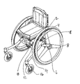
FIG. 1 is a wheelchair according to the invention in a four wheel setup in a perspective view,
FIG. 2 is a wheelchair according to the invention in a three wheel setup in a perspective view,
FIG. 3 is an embodiment of the wheel chair as seen from the back side,
FIG. 4 is a wheelchair shown adjusted with two different widths,
FIGS. 5 and 6 shows a wheelchair adjusted to two different heights,
FIGS. 7 and 8 show a wheelchair with the seat tilted in two different angels, and
FIG. 9 shows a foot rest assembly.
DETAILED DESCRIPTION OF THE PREFERRED EMBODIMENTS
With reference to FIG. 1 a wheelchair is built upon a frame 2, the frame comprises at least two back apertures of which only one 4 can be seen. The back aperture 4 is receiving a spacer 6. The back wheel 8 is connected to the spacer 6. The back spacer 6 comprises several holes of which one is selected to secure the back wheel 1 to the wheelchair. By using different sizes of the back wheel 8 or another hole in the spacer 6 the height of the wheelchair can be changed. The frame further comprises two front apertures, of which only one 10 can be seen. The front aperture 10 is receiving a length of front spacer 12, which is connected to a leg member 14. The leg member is further connected to an aperture 18 of the back spacer 6, and to a front wheel 16. The track with of the wheels can be changed by changing the length of the front and back spacers 12,6 received by the front and back apertures 4,10, respectively. In this embodiment the elongated member of the leg member 14 has an oval cross-section, and the aperture 18 of the back spacer 6 has a corresponding oval shape. The leg member shown in this embodiment of the invention is secured in a stable manner to the wheelchair.
In FIG. 2 an embodiment of the wheelchair according to the invention is shown in a three wheel setup. In the three wheel setup a single leg member 20 is received by a central front aperture 22 of the frame 2. In this setup the front apertures 10 and the oval apertures 18 of the back spacers are not used. The chair can easily be changed back and forth between a four wheel setup and a three wheel setup. In the three wheel setup the wheelchair has a more sporty look, and also more sporty properties. It is e.g. easier to turn the wheelchair for the user. The three wheel setup is therefore often adequate for a younger and active user.
In FIG. 3 an embodiment of the wheel chair is seen from the back side. A back frame 22 is connected to a number of brackets 23. The brackets are having elongated holes, and the connection of the back frame 22 to the brackets 23 are made with fasteners penetrating the back frame 22 and the elongated holes of the brackets 23. The width of the back support can then easily be adjusted to a size which fits the user. Of course, the length of the brackets as well as the size of the back frame 22 gives some limits of the possibility for the adjustment of the width of the back support. If necessary, the back frame 22 can be changed to a back frame of completely different size to extend the range of which the back support width can be adjusted.
In FIG. 4 the same wheelchair is shown adjusted with two different widths. It can be seen that the bigger width of the wheelchair in FIG. 4 b compared with FIG. 4 a is achieved by having a longer length of the back spacers 6 and front spacers 12 outside the front and back apertures than in FIG. 4 b. Furthermore, the brackets 23 of the back support are moved apart from each other in FIG. 4 b. The seat 30 is made adjustable in a similar manner. Inside the seat 30 a number of support members 32 are slidingly arranged.
In FIGS. 5 and 6 it is shown how the height and the length of the wheelchair can be changed by using another central leg member 20 and mounting the wheel 8 in another hole of the back spacer 6. The back spacer is provided with several holes. The height of the seat can be changed by mounting the wheel 8 in a lower hole of the back spacer 6. It is also possible to make the wheelchair longer by changing the central leg member 20 to a longer type of the same central leg member 20′. The same effect can be obtained in the four wheel setup by changing the to front leg members.
In FIGS. 7 and 8 it is shown how the seat can be tilted in space. The means for tilting the seat of this invention is especially advantageous because they maintain the centre of gravity between the front and back wheels. The means for tilting the seat comprises a hinge construction. The hinge is constructed by a first hinge member 30, which is pivotally connected to the seat and pivotally connected to the frame 2. The hinge construction further comprises a second hinge member 32, which is pivotally connected to the frame 2 and pivotally connected to the seat. A gas damper 34 is pivotally connected to the first hinge member 30 and to the seat. The gas damper 34 is a blocking gas damper, which means that it can be released when the tilt of the seat has to be changed and blocked afterwards.
FIG. 9 illustrates a foot rest arranged at the end of a pipe-shaped member 35. The pipe member 35 can for example be attached to the frame in the same manner as the front wheel 20 (see FIGS. 5 and 6). In the pipe member 35 means 36 for fastening a hub member 37 are arranged. The hub member 37 is fastened by for example a bolt (not shown) going through the hub member and through a hole 36 in the pipe member 35. In this manner, the hub can very easily and securely be fastened to the pipe member 35. The hub member is articulately connected to a beam member 38 which again, though a pivot point 39 is connected to the actual plate-shaped foot rests 40. Both in the pivot 39 and the hub member 37, means are provided such that the beam member 38 can be locked in an angle relative to the pipe member 35, and the plate-shaped foot rests 40 can be locked in an angular relationship with the beam member 38 such that any desired position of foot rests can be attained. In this manner, a very flexible and comfortable foot rest is provided. Furthermore, the two foot rests can be arranged in different means 36 along the pipe 35 such that differences in leg lengths or foot rest comfort positions can be accommodated.

Claims (6)

1. A wheelchair comprising a seat, a back support and a number of wheels, provided with means for adjusting the width of the seat, means for adjusting the width of the back support and means for adjusting the width of the track of the wheels, and further that said means for adjusting the width of the track of the wheels comprises a frame comprising a pair of back apertures, a pair of front apertures, and a central front aperture, where each of the back apertures are adapted for receiving a variable length of a back spacer, each front aperture adapted for receiving a variable length of a front spacer, said back spacer connected to a displacer connected to a back wheel, said displacer comprising an aperture adapted for interlocking a leg member, said leg member being connected to said front spacer, said leg member being connected to a front wheel, said central front aperture being an aperture adapted to interlock a central leg member being connected to a wheel, and where said means for adjusting the width of the seat comprises two support members slidingly arranged in a seat plate.
2. A wheelchair according to claim 1, comprising at least one foot rest attached to said wheelchair with releasable attachment means, said releasable attachment means comprising a hook shaped member pivotally secured to said wheelchair, for engagement with a hook shaped member of said foot rest.
3. A wheelchair according to claim 1, where said means for adjusting the width of the back support comprises a back frame comprising at least one track or aperture, a bracket comprising at least one aperture, at least one of the apertures and tracks respectively being elongated, at least one fastener penetrating at least one aperture of the back frame and one aperture of the bracket, said fastener securing the back frame to the bracket.
4. A wheelchair according to claim 1, comprising means for tilting the seat and for maintaining an essentially constant centre of gravity, said means comprising a lockable adjustment means, a first and a second hinge member, both hinge member pivotally connected to said frame and pivotally connected to said seat, said adjustment means pivotally connected to said first hinge member and to said seat, said adjustment means comprising blocking means.
5. A wheelchair according to claim 4, wherein the lockable adjustment means may be chosen from a blocking gas damper, an electrical actuator, a rack and pinion electrically operated by means of a step motor, a spindle axle, or any other similar means.
6. A wheelchair according to claim 1, where said seat is slidingly connected to said frame.
US10/549,924 2003-03-20 2004-03-22 Active wheelchair Expired - Fee Related US7404567B2 (en)

Applications Claiming Priority (3)

Application Number Priority Date Filing Date Title
DKPA200300421 2003-03-20
PCT/DK2004/000196 WO2004082548A2 (en) 2003-03-20 2004-03-22 Active wheelchair

Publications (2)

Publication Number Publication Date
US20060181051A1 US20060181051A1 (en) 2006-08-17
US7404567B2 true US7404567B2 (en) 2008-07-29

Family

ID=33016785

Family Applications (1)

Application Number Title Priority Date Filing Date
US10/549,924 Expired - Fee Related US7404567B2 (en) 2003-03-20 2004-03-22 Active wheelchair

Country Status (3)

Country Link
US (1) US7404567B2 (en)
EP (1) EP1635754A2 (en)
WO (1) WO2004082548A2 (en)

Cited By (7)

* Cited by examiner, † Cited by third party
Publication number Priority date Publication date Assignee Title
US20090072510A1 (en) * 2007-09-14 2009-03-19 Alexander Mueller Wheelchair suitable for performing abduction actions
US8585071B2 (en) 2010-12-31 2013-11-19 Stephen C. Golden, JR. Releasable forward wheel apparatus for a wheelchair
US9010787B2 (en) 2013-03-04 2015-04-21 Ki Mobility Tilt-in-space wheelchair using multiple controlling paths
USD732439S1 (en) 2012-07-26 2015-06-23 Stryker Corporation Wheelchair armrests
US9554955B2 (en) 2007-10-01 2017-01-31 Pride Mobility Products Corporation Dual-track tilt mechanism
US9655794B2 (en) * 2015-10-07 2017-05-23 Edward T. Bednarz, III Adjustable wheelchair
US10080438B2 (en) 2015-09-21 2018-09-25 Stryker Corporation Patient support apparatus

Families Citing this family (6)

* Cited by examiner, † Cited by third party
Publication number Priority date Publication date Assignee Title
FR2880798B1 (en) * 2005-01-14 2007-04-13 Dupont Medical Sa WHEELCHAIR
NZ539543A (en) * 2005-04-20 2008-02-29 Graham John Mahy Vehicle with adjustable track width and wheelbase
US7569002B2 (en) * 2005-11-14 2009-08-04 Avinoam Nativ Exercise wheelchair
US20080231005A1 (en) * 2007-03-20 2008-09-25 Clark Ivan P Wheel chair
DE102007057363B4 (en) 2007-11-27 2011-03-24 Gregor Wolf wheelchair
FR3026942A1 (en) * 2014-10-13 2016-04-15 Transtech Aquitaine HANDISPORT MULTI ADAPTABLE WHEELCHAIR

Citations (24)

* Cited by examiner, † Cited by third party
Publication number Priority date Publication date Assignee Title
US3937490A (en) * 1973-06-27 1976-02-10 Nasr Ibrahim Abdelrahim Mohame Wheelchair
US4310167A (en) 1980-05-15 1982-01-12 The University Of Virginia Alumni Patents Foundation Center of gravity wheelchair with articulated chassis
US4360213A (en) * 1980-04-01 1982-11-23 Rudwick Lawrence A Sport type wheel chair
GB2171898A (en) 1985-02-19 1986-09-10 Remploy Ltd Reclining chairs
US4730842A (en) * 1986-04-18 1988-03-15 Wheel Ring, Inc. Adjustable wheelchair
US4813693A (en) * 1986-09-30 1989-03-21 Invacare Corporation Adjustable child's wheelchair
EP0329002A2 (en) 1988-02-16 1989-08-23 Mulholland Designs, Inc. Reclinable wheelchair
US4989890A (en) * 1986-09-30 1991-02-05 Invacare Corporation Length and width adjustable wheelchair
US5020618A (en) 1989-07-12 1991-06-04 Eaton Corporation Full hydraulic power steering apparatus
WO1991017077A1 (en) 1990-04-27 1991-11-14 Medical Composite Technology Modular wheelchair
US5154438A (en) 1991-09-30 1992-10-13 Barclay Hugh W Tilting and folding wheelchair
EP0512650A1 (en) 1991-05-08 1992-11-11 Richard Van Seenus Nederland B.V. Wheelchair
WO1993000060A1 (en) 1991-06-20 1993-01-07 Tartan Rehab Limited Sliding seat for wheelchairs
US5297021A (en) * 1992-11-16 1994-03-22 Koerlin James M Zero shear recliner/tilt wheelchair seat
US5320373A (en) 1990-05-24 1994-06-14 Medical Composite Technology Molded-composite chassis for a wheelchair
EP0841052A2 (en) 1996-11-12 1998-05-13 Invacare Corporation Wheelchair with camber adjustment
US5782483A (en) 1995-06-05 1998-07-21 Adorno/Rogers Technology, Inc. Adjustable wheelbase wheelchair
EP0885605A1 (en) 1997-06-20 1998-12-23 Invacare (Deutschland) GmbH Wheelchair
US5943734A (en) 1993-07-27 1999-08-31 Teksource, Lc Mount for mounting a caster wheel to a wheelchair
EP0945114A1 (en) 1998-02-25 1999-09-29 Aquarius B.V. Tiltable wheelchair having a supporting spring member
US5984418A (en) * 1997-04-28 1999-11-16 Crown Therapeutics, Inc. Adjustable seat for wheelchairs
US6161856A (en) 1998-11-13 2000-12-19 Invacare Corporation Wheelchair suspension system
US6352307B1 (en) * 1995-11-15 2002-03-05 Permobil Ab Multipositioning system seat
US6467788B1 (en) 2001-06-04 2002-10-22 Tianfu Li Tilt-in-place wheelchair having adjustable wheelbase width

Patent Citations (24)

* Cited by examiner, † Cited by third party
Publication number Priority date Publication date Assignee Title
US3937490A (en) * 1973-06-27 1976-02-10 Nasr Ibrahim Abdelrahim Mohame Wheelchair
US4360213A (en) * 1980-04-01 1982-11-23 Rudwick Lawrence A Sport type wheel chair
US4310167A (en) 1980-05-15 1982-01-12 The University Of Virginia Alumni Patents Foundation Center of gravity wheelchair with articulated chassis
GB2171898A (en) 1985-02-19 1986-09-10 Remploy Ltd Reclining chairs
US4730842A (en) * 1986-04-18 1988-03-15 Wheel Ring, Inc. Adjustable wheelchair
US4813693A (en) * 1986-09-30 1989-03-21 Invacare Corporation Adjustable child's wheelchair
US4989890A (en) * 1986-09-30 1991-02-05 Invacare Corporation Length and width adjustable wheelchair
EP0329002A2 (en) 1988-02-16 1989-08-23 Mulholland Designs, Inc. Reclinable wheelchair
US5020618A (en) 1989-07-12 1991-06-04 Eaton Corporation Full hydraulic power steering apparatus
WO1991017077A1 (en) 1990-04-27 1991-11-14 Medical Composite Technology Modular wheelchair
US5320373A (en) 1990-05-24 1994-06-14 Medical Composite Technology Molded-composite chassis for a wheelchair
EP0512650A1 (en) 1991-05-08 1992-11-11 Richard Van Seenus Nederland B.V. Wheelchair
WO1993000060A1 (en) 1991-06-20 1993-01-07 Tartan Rehab Limited Sliding seat for wheelchairs
US5154438A (en) 1991-09-30 1992-10-13 Barclay Hugh W Tilting and folding wheelchair
US5297021A (en) * 1992-11-16 1994-03-22 Koerlin James M Zero shear recliner/tilt wheelchair seat
US5943734A (en) 1993-07-27 1999-08-31 Teksource, Lc Mount for mounting a caster wheel to a wheelchair
US5782483A (en) 1995-06-05 1998-07-21 Adorno/Rogers Technology, Inc. Adjustable wheelbase wheelchair
US6352307B1 (en) * 1995-11-15 2002-03-05 Permobil Ab Multipositioning system seat
EP0841052A2 (en) 1996-11-12 1998-05-13 Invacare Corporation Wheelchair with camber adjustment
US5984418A (en) * 1997-04-28 1999-11-16 Crown Therapeutics, Inc. Adjustable seat for wheelchairs
EP0885605A1 (en) 1997-06-20 1998-12-23 Invacare (Deutschland) GmbH Wheelchair
EP0945114A1 (en) 1998-02-25 1999-09-29 Aquarius B.V. Tiltable wheelchair having a supporting spring member
US6161856A (en) 1998-11-13 2000-12-19 Invacare Corporation Wheelchair suspension system
US6467788B1 (en) 2001-06-04 2002-10-22 Tianfu Li Tilt-in-place wheelchair having adjustable wheelbase width

Cited By (12)

* Cited by examiner, † Cited by third party
Publication number Priority date Publication date Assignee Title
US20090072510A1 (en) * 2007-09-14 2009-03-19 Alexander Mueller Wheelchair suitable for performing abduction actions
US9554955B2 (en) 2007-10-01 2017-01-31 Pride Mobility Products Corporation Dual-track tilt mechanism
US8585071B2 (en) 2010-12-31 2013-11-19 Stephen C. Golden, JR. Releasable forward wheel apparatus for a wheelchair
USD732439S1 (en) 2012-07-26 2015-06-23 Stryker Corporation Wheelchair armrests
USD742286S1 (en) 2012-07-26 2015-11-03 Stryker Corporation Wheelchair rear wheels with supports
USD743305S1 (en) 2012-07-26 2015-11-17 Stryker Corporation Wheelchair castor posts
US9010787B2 (en) 2013-03-04 2015-04-21 Ki Mobility Tilt-in-space wheelchair using multiple controlling paths
US10080438B2 (en) 2015-09-21 2018-09-25 Stryker Corporation Patient support apparatus
US10681982B2 (en) 2015-09-21 2020-06-16 Stryker Corporation Patient support apparatus
US11382811B2 (en) 2015-09-21 2022-07-12 Stryker Corporation Patient support apparatus
US11813213B2 (en) 2015-09-21 2023-11-14 Stryker Corporation Patient support apparatus
US9655794B2 (en) * 2015-10-07 2017-05-23 Edward T. Bednarz, III Adjustable wheelchair

Also Published As

Publication number Publication date
WO2004082548A8 (en) 2006-02-09
WO2004082548A2 (en) 2004-09-30
EP1635754A2 (en) 2006-03-22
WO2004082548A3 (en) 2006-05-04
US20060181051A1 (en) 2006-08-17

Similar Documents

Publication Publication Date Title
US7404567B2 (en) Active wheelchair
US9532912B2 (en) Wheelchair seat assembly
US5996716A (en) Adjustable wheelchair
US5074620A (en) Wheelchair seat system
US4730842A (en) Adjustable wheelchair
US7360781B2 (en) Foldable wheelchair and axle plate therefor
US5480172A (en) Three-wheeled competition wheelchair having an adjustable center of mass
EP1416895B1 (en) Wheelchairs
US7510200B1 (en) Wheelchair
US8336898B2 (en) Reconfigurable tilt wheelchair
US5360224A (en) Wheelchair frame assembly and components for use thereon
US20040188979A1 (en) Center-of-gravity tilt-in-space wheelchair
US5915709A (en) Modular cross member assembly for adjustable wheelchair
CA2330415A1 (en) Orthotic walker
US20090283983A1 (en) Wheelchair construction
JP3493000B2 (en) Wheelchair back recliner kit
US5573260A (en) Sport wheelchair having a T-frame
US20040189076A1 (en) Seating assembly for wheelchairs and strollers
EP1824724B1 (en) Foldable wheelchair and axle plate therefor
US6886843B1 (en) Seating frame for wheelchair
EP0526088B1 (en) Wheelchairs
EP2174630B1 (en) Wheelchair comprising a foot support
EP0761195B1 (en) Multifunctional wheelchair
US7032974B1 (en) Headrest assembly
EP0908167A2 (en) Reversible seat for front wheel drive and rear wheel drive power wheelchair having stepless angular adjustment

Legal Events

Date Code Title Description
AS Assignment

Owner name: R82 A/S, DENMARK

Free format text: ASSIGNMENT OF ASSIGNORS INTEREST;ASSIGNOR:MOLLER, FLEMMING;REEL/FRAME:017162/0548

Effective date: 20050919

STCF Information on status: patent grant

Free format text: PATENTED CASE

FPAY Fee payment

Year of fee payment: 4

FPAY Fee payment

Year of fee payment: 8

FEPP Fee payment procedure

Free format text: MAINTENANCE FEE REMINDER MAILED (ORIGINAL EVENT CODE: REM.); ENTITY STATUS OF PATENT OWNER: SMALL ENTITY

LAPS Lapse for failure to pay maintenance fees

Free format text: PATENT EXPIRED FOR FAILURE TO PAY MAINTENANCE FEES (ORIGINAL EVENT CODE: EXP.); ENTITY STATUS OF PATENT OWNER: SMALL ENTITY

STCH Information on status: patent discontinuation

Free format text: PATENT EXPIRED DUE TO NONPAYMENT OF MAINTENANCE FEES UNDER 37 CFR 1.362