US7433026B2 - Microscope with LED illumination source - Google Patents
Microscope with LED illumination source Download PDFInfo
- Publication number
- US7433026B2 US7433026B2 US11/313,365 US31336505A US7433026B2 US 7433026 B2 US7433026 B2 US 7433026B2 US 31336505 A US31336505 A US 31336505A US 7433026 B2 US7433026 B2 US 7433026B2
- Authority
- US
- United States
- Prior art keywords
- light
- leds
- pulse width
- characteristic
- biological specimen
- Prior art date
- Legal status (The legal status is an assumption and is not a legal conclusion. Google has not performed a legal analysis and makes no representation as to the accuracy of the status listed.)
- Active, expires
Links
- 238000005286 illumination Methods 0.000 title description 9
- 238000000034 method Methods 0.000 claims abstract description 55
- 230000000694 effects Effects 0.000 claims description 25
- 239000000758 substrate Substances 0.000 claims description 12
- 230000004044 response Effects 0.000 claims description 10
- 230000002380 cytological effect Effects 0.000 abstract description 8
- 239000003086 colorant Substances 0.000 abstract description 7
- 210000004027 cell Anatomy 0.000 description 18
- 238000003384 imaging method Methods 0.000 description 8
- 238000004458 analytical method Methods 0.000 description 6
- 210000000805 cytoplasm Anatomy 0.000 description 5
- 201000010099 disease Diseases 0.000 description 4
- 208000037265 diseases, disorders, signs and symptoms Diseases 0.000 description 4
- 230000008569 process Effects 0.000 description 4
- 238000010186 staining Methods 0.000 description 4
- 230000002159 abnormal effect Effects 0.000 description 3
- 230000005856 abnormality Effects 0.000 description 3
- 238000012986 modification Methods 0.000 description 3
- 230000004048 modification Effects 0.000 description 3
- WZUVPPKBWHMQCE-UHFFFAOYSA-N Haematoxylin Chemical compound C12=CC(O)=C(O)C=C2CC2(O)C1C1=CC=C(O)C(O)=C1OC2 WZUVPPKBWHMQCE-UHFFFAOYSA-N 0.000 description 2
- 238000001574 biopsy Methods 0.000 description 2
- 238000013461 design Methods 0.000 description 2
- 238000003745 diagnosis Methods 0.000 description 2
- 238000010586 diagram Methods 0.000 description 2
- 239000011521 glass Substances 0.000 description 2
- 239000011824 nuclear material Substances 0.000 description 2
- 238000009595 pap smear Methods 0.000 description 2
- 206010008342 Cervix carcinoma Diseases 0.000 description 1
- 241000276498 Pollachius virens Species 0.000 description 1
- 208000006105 Uterine Cervical Neoplasms Diseases 0.000 description 1
- 208000003464 asthenopia Diseases 0.000 description 1
- 230000015572 biosynthetic process Effects 0.000 description 1
- 210000001124 body fluid Anatomy 0.000 description 1
- 239000010839 body fluid Substances 0.000 description 1
- 201000010881 cervical cancer Diseases 0.000 description 1
- 210000003679 cervix uteri Anatomy 0.000 description 1
- 239000003153 chemical reaction reagent Substances 0.000 description 1
- 238000004590 computer program Methods 0.000 description 1
- 230000001086 cytosolic effect Effects 0.000 description 1
- 238000013144 data compression Methods 0.000 description 1
- 239000000975 dye Substances 0.000 description 1
- 238000005516 engineering process Methods 0.000 description 1
- 239000000834 fixative Substances 0.000 description 1
- 229910052736 halogen Inorganic materials 0.000 description 1
- 239000000463 material Substances 0.000 description 1
- 230000001575 pathological effect Effects 0.000 description 1
- 239000002243 precursor Substances 0.000 description 1
- 238000002360 preparation method Methods 0.000 description 1
- 230000005855 radiation Effects 0.000 description 1
- 238000007790 scraping Methods 0.000 description 1
- -1 sodium-halide Inorganic materials 0.000 description 1
- 239000000243 solution Substances 0.000 description 1
- 238000001228 spectrum Methods 0.000 description 1
- 239000012192 staining solution Substances 0.000 description 1
- 238000012360 testing method Methods 0.000 description 1
- 210000000115 thoracic cavity Anatomy 0.000 description 1
- 210000001519 tissue Anatomy 0.000 description 1
- 230000000007 visual effect Effects 0.000 description 1
- 238000012800 visualization Methods 0.000 description 1
- 229910052724 xenon Inorganic materials 0.000 description 1
- FHNFHKCVQCLJFQ-UHFFFAOYSA-N xenon atom Chemical compound [Xe] FHNFHKCVQCLJFQ-UHFFFAOYSA-N 0.000 description 1
Images


Classifications
-
- G—PHYSICS
- G02—OPTICS
- G02B—OPTICAL ELEMENTS, SYSTEMS OR APPARATUS
- G02B21/00—Microscopes
- G02B21/06—Means for illuminating specimens
-
- G—PHYSICS
- G02—OPTICS
- G02B—OPTICAL ELEMENTS, SYSTEMS OR APPARATUS
- G02B21/00—Microscopes
- G02B21/06—Means for illuminating specimens
- G02B21/08—Condensers
-
- G—PHYSICS
- G01—MEASURING; TESTING
- G01J—MEASUREMENT OF INTENSITY, VELOCITY, SPECTRAL CONTENT, POLARISATION, PHASE OR PULSE CHARACTERISTICS OF INFRARED, VISIBLE OR ULTRAVIOLET LIGHT; COLORIMETRY; RADIATION PYROMETRY
- G01J3/00—Spectrometry; Spectrophotometry; Monochromators; Measuring colours
- G01J3/12—Generating the spectrum; Monochromators
- G01J3/18—Generating the spectrum; Monochromators using diffraction elements, e.g. grating
-
- G—PHYSICS
- G01—MEASURING; TESTING
- G01N—INVESTIGATING OR ANALYSING MATERIALS BY DETERMINING THEIR CHEMICAL OR PHYSICAL PROPERTIES
- G01N33/00—Investigating or analysing materials by specific methods not covered by groups G01N1/00 - G01N31/00
- G01N33/48—Biological material, e.g. blood, urine; Haemocytometers
-
- G—PHYSICS
- G02—OPTICS
- G02B—OPTICAL ELEMENTS, SYSTEMS OR APPARATUS
- G02B21/00—Microscopes
- G02B21/06—Means for illuminating specimens
- G02B21/08—Condensers
- G02B21/082—Condensers for incident illumination only
- G02B21/084—Condensers for incident illumination only having annular illumination around the objective
-
- G—PHYSICS
- G06—COMPUTING; CALCULATING OR COUNTING
- G06V—IMAGE OR VIDEO RECOGNITION OR UNDERSTANDING
- G06V10/00—Arrangements for image or video recognition or understanding
- G06V10/10—Image acquisition
- G06V10/12—Details of acquisition arrangements; Constructional details thereof
- G06V10/14—Optical characteristics of the device performing the acquisition or on the illumination arrangements
- G06V10/141—Control of illumination
-
- G—PHYSICS
- G06—COMPUTING; CALCULATING OR COUNTING
- G06V—IMAGE OR VIDEO RECOGNITION OR UNDERSTANDING
- G06V20/00—Scenes; Scene-specific elements
- G06V20/60—Type of objects
- G06V20/69—Microscopic objects, e.g. biological cells or cellular parts
- G06V20/693—Acquisition
Definitions
- the present invention relates to microscope imaging systems, and more particularly, to systems for displaying magnified images of stained specimens.
- Cytology is the branch of biology dealing with the study of the formation, structure, and function of cells. As applied in a laboratory setting, cytologists, cytotechnologists, and other medical professionals make medical diagnoses of a patient's condition based on visual examination of a specimen of the patient's cells.
- a typical cytological technique is a “Pap smear” test, in which cells are scraped from a woman's cervix and analyzed in order to detect the presence of abnormal cells, a precursor to the onset of cervical cancer. Cytological techniques are also used to detect abnormal cells and disease in other parts of the human body.
- Cytological techniques are widely employed because collection of cell samples for analysis is generally less invasive than traditional surgical pathological procedures such as biopsies, whereby a tissue specimen is excised from the patient using specialized biopsy needles having spring loaded translatable stylets, fixed cannulae, and the like.
- Cell samples may be obtained from the patient by a variety of techniques including, for example, by scraping or swabbing an area, or by using a needle to aspirate body fluids from the chest cavity, bladder, spinal canal, or other appropriate area.
- the cell samples are often placed in solution and subsequently collected and transferred to a glass slide for viewing under magnification. Fixative and staining solutions are typically applied to the cells on the glass slide, often called a cell smear, for facilitating examination and for preserving the specimen for archival purposes.
- a traditional multicolored stain is desirable for staining cell smears for certain cytological analyses. It is advantageous to stain the nucleus and the cytoplasm of the specimen with different colors, so that the nuclear material and cytoplasmic material can be readily distinguished either visually or by automated imaging equipment.
- the cytoplasm is transparent, whereas the nucleus is transparent to opaque. This staining pattern allows the cytologist to distinguish cells which are morphologically abnormal indicated, for example, by nuclear material which is excessively large and/or dark in color.
- cytologists find the variety of colors of the traditional stains, particularly the Papanicolaou stain, helpful to reduce eye strain and to aid diagnosis.
- the type of stain chosen may depend on the type of cells under examination, as well as the specific abnormality or disease to be diagnosed. For this reason, various stains may be used in various laboratory settings.
- the improved illumination source allows for color balancing and intensity adjustment. Because the color and intensity of the light can be tailored to conditions of the system, such as the type(s) of stains used, the type of cells in the sample, and the type of abnormalities/diseases to be detected, diagnosis by a human cytologist or an imaging system may be facilitated.
- a method for viewing a biological specimen comprises illuminating the biological specimen with a light source having light emitting diodes (LEDs) arranged in a plurality of unique color groupings, and generating a magnified image of the illuminated biological specimen.
- the LEDs may comprise LED dies disposed on a single substrate to form a compact LED module.
- the method further comprises selecting a desired characteristic of light emitted by the light source, e.g., a color balance or a light intensity.
- the desired light characteristic may be, e.g., selected in response to a manual input or automated input. Selection of desired light characteristic may be based on a viewing condition, e.g., a type of stain used on a biological specimen. For example, the light characteristic can be customized to discern differently stained parts of the biological specimen.
- the method further comprises generating a plurality of drive signals, each of which has a characteristic based on the selected light characteristic.
- the drive signal characteristic may be an amplitude or a pulse width.
- the method further comprises supplying the plurality of LED color groupings with the respective plurality of drive signals, wherein light intensities of the LED color groupings are independently controlled to effect the desired light characteristic.
- desired light intensities of the LED color groupings are computed based on the selected light characteristic, so that the characteristics of the drive signals can be determined.
- a system for viewing a biological specimen comprises a microscope configured for generating a magnified image of the biological specimen, and a light source configured for illuminating the biological specimen.
- the light source has LEDs arranged in a plurality of unique color groupings, e.g., red, blue, and green. Again, to miniaturize the light source, the LEDs may comprise LED dies disposed on a single substrate to form a compact LED module.
- the system further comprises an input device configured for receiving information to effect a desired characteristic of light emitted by the light source, e.g., a color balance or a light intensity.
- the input device may, e.g., be a user input device configured for selecting the desired light characteristic.
- the system may optionally comprise a processor configured for computing the desired light characteristic, e.g., based on a viewing condition, such as a type of stain used on the biological specimen.
- the system further comprises control circuitry configured for supplying the plurality of LED color groupings with a respective plurality of drive signals, each of which has a characteristic (e.g., amplitude or pulse width) based on the information received by the input device, wherein light intensities of the LED color groupings are independently controlled to effect the desired light characteristic.
- the control circuitry may optionally comprise a pulse width modulation controller configured for generating pulse width modulated control signals, and drive circuitry configured for supplying pulse width modulated drive signals to the respective plurality of LED color groupings in response to the control signals.
- a method for viewing a biological specimen comprises illuminating the biological specimen with a light source having LEDs, and generating a magnified image of the illuminated biological specimen.
- the LEDs may optionally be arranged in a plurality of unique color groupings. Again, to miniaturize the light source, the LEDs may comprise LED dies disposed on a single substrate to form a compact LED module.
- the method further comprises dynamically selecting a desired characteristic of light emitted by the light source, e.g., a color balance or a light intensity.
- the desired light characteristic may be, e.g., selected in response to a manual input or automated input. Selection of desired light characteristic may be based on a viewing condition, e.g., a type of stain used on biological specimen. For example, the light characteristic can be customized to discern differently stained parts of the biological specimen.
- the method further comprises generating one or more pulse width modulated drive signals, each of which has a pulse width based on the desired light characteristic, and supplying the plurality of LEDs with the one or more pulse width modulated drive signals, wherein light intensities of the LEDs are controlled to effect the desired light characteristic.
- the one or more pulse width modulated drive signals comprises a plurality of pulse width modulated drive signals that are respectively supplied to the plurality of LEDs, so that the light intensities of the LEDs can be independently controlled to effect the desired light characteristic.
- the plurality of pulse width modulated drive signals can be respectively supplied to the plurality of LED color groupings, so that the light intensities of the LED color groupings can be independently controlled to effect the desired light characteristic.
- the pulse width for each pulse width modulated signal is computed based on the selected light characteristic.
- a system for viewing a biological specimen comprises a microscope configured for generating a magnified image of the biological specimen, and a light source configured for illuminating the biological specimen.
- the light source has LEDs arranged in a plurality of unique color groupings, e.g., red, blue, and green. Again, to miniaturize the light source, the LEDs may comprise LED dies disposed on a single substrate to form a compact LED module.
- the system further comprises an input device configured for dynamically receiving information to effect a desired characteristic of light emitted by the light source, e.g., a color balance or a light intensity.
- the input device may, e.g., be a user input device configured for selecting the desired light characteristic.
- the system may optionally comprise a processor configured for computing the desired light characteristic, e.g., based on a viewing condition, such as a type of stain used on the biological specimen.
- the system further comprises control circuitry configured for supplying the plurality of LEDs with one or more drive signals, each of which has a characteristic (e.g., amplitude or pulse width) based on the information received by the input device, wherein light intensities of the LEDs are controlled to effect the desired light characteristic.
- the one or more pulse width modulated drive signals comprises a plurality of pulse width modulated drive signals that are respectively supplied to the plurality of LEDs, so that the light intensities of the LEDs can be independently controlled to effect the desired light characteristic.
- the plurality of pulse width modulated drive signals can be respectively supplied to the plurality of LED color groupings, so that the light intensities of the LED color groupings can be independently controlled to effect the desired light characteristic.
- the control circuitry may optionally comprise a pulse width modulation controller configured for generating pulse width modulated control signals, and drive circuitry configured for supplying pulse width modulated drive signals to the respective plurality of LED color groupings in response to the control signals.
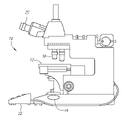
- FIG. 1 is a side view showing a one embodiment of a microscope constructed in accordance with the present inventions
- FIG. 2 is a front view of the microscope of FIG. 1 ;
- FIGS. 3A-3C are plan views of exemplary light emitting diode (LED) modules used as the illumination source in the microscope of FIG. 1 ;
- FIG. 4 is a block diagram of control circuitry used to control the LED module of FIG. 3A ;
- FIG. 5 is a flow chart illustrating one method for controlling the characteristics of light emitted by the illumination source of the microscope of FIG. 1 in accordance with the present inventions.
- FIG. 6 is a flow chart illustrating one method for controlling the characteristics of light emitted by the illumination source of the microscope of FIG. 1 in accordance with the present inventions.
- the microscope 10 includes a stage 12 for mounting a specimen, and a light source 14 for illuminating the specimen. As will be described in further detail below, the color balance and intensity of the light emitted by the light source 14 can be adjusted. To this end, the microscope 10 further includes control circuitry 16 for adjusting the color balance and intensity of the emitted light.
- the microscope 10 further includes plurality of objective lenses 18 for magnifying light received from the specimen to form a magnified image of the specimen, and an ocular lens 20 used to observe the magnified image formed by the objective lens 18 .
- the microscope 10 further includes a control station 22 for receiving an input.
- the control station 22 is illustrated as a stand-alone control station, those skilled in the art will appreciate that the control station 22 can be implemented in a number of ways.
- the control station 22 could be built into the same structure that carries the stage 12 , light source 14 , and lenses 18 , 20 .
- the light source control circuitry 16 is shown in the illustrated embodiment as being incorporated into the control station 22 , it can likewise be incorporated into the same structure that carries the stage 12 , light source 14 , and lenses 18 , 20 .
- the control station 22 receives a manual input from a user.
- the control station 22 may include appropriate user input devices, such as knobs, dials, buttons, keyboard, mouse, or the like.
- the control station 22 could be implemented in a computer or other user workstation, and could include a graphical user interface (GUI) for interfacing with a user.
- GUI graphical user interface
- the user input may specify a desired color balance and intensity, in which case, the light source control circuitry 16 adjusts the color balance and intensity of the light source 14 to match the user-specified color and intensity.
- the user input may specify one or more specimen viewing conditions, such as, for example, the type of stain(s) used on the specimen, the type of cells in the specimen, the type of abnormalities/diseases to be detected, the ambient conditions in the laboratory, and the like.
- the light source control circuitry 16 computes a desired color balance and light intensity based on the viewing conditions (e.g., by referring to a look-up table), and adjusts the color balance and intensity of the light source 14 to match the computed color balance and intensity.
- the specimen viewing conditions may be automatically inputted.
- the control station 22 may be equipped with a bar code reader or other reader configured to read information printed on a slide carrying the cytological specimen.
- the control station 22 may also be equipped with a sensor configured to measure the ambient lighting of the room.
- the color balance and intensity of the light emitted by the light source 14 will be dynamically adjusted to provide optimum viewing conditions for the specimen. For example, if a cytological specimen is provided, a cytologist may wish to view a sample that includes blue-stained nuclei in green-stained cytoplasm. In this case, the color balance may be adjusted to increase the amount of green light. Adjusting the color balance thusly would minimize the contrast between the cytoplasm and the background, allowing the cytologist to better view the nuclei. Similarly, the intensity of the light source may be adjusted to allow visualization of the structure within darkly stained nuclei, or within a tight and dense grouping of cells.
- the control circuitry 16 may include one or more potentiometers or other appropriate circuit elements, which output analog drive signals to control the light source 14 .
- the control circuitry 16 may include a digital/analog converter for converting digital signals representing the desired color balance and light intensity into analog signals to control the light source 14 .
- the control circuitry 16 may include a processor for computing a desired color balance and light intensity based on the viewing conditions. The nature of the light source control circuitry 16 will also depend on the nature of the light source 14 used, as described in further detail below.
- the light source 14 advantageously includes a plurality of light emitting diodes (LEDs) of two or more color groups.
- LEDs light emitting diodes
- the intensities of the LEDs, or at least the collective intensity of each LED color grouping may be independently controlled to adjust the color balance (i.e., tint) and intensity of the light provided to the biological specimen for viewing by a human or for imaging with a camera.
- any color in the visible or even invisible spectrum, including white light can be produced.
- the LED module 14 includes a plurality of LEDs 24 (illustrated as 24 r , 24 b , 24 g ), which as made clear in FIGS. 3A-3C , can be arranged in a module that is circular, annular, rectangular, or some other shape, and may be distributed within the module in a staggered, rectilinear, annular, or other configuration.
- the LEDs 24 output three colors of light.
- LEDs 24 r may output red light
- LEDs 24 b may output blue light
- LEDs 24 g may output green light.
- the LEDs 24 dies may output specific wavelengths that are selected for the stains used with the specimen.
- the LED module 14 is illustrated in FIGS. 3A-3C as containing three color groupings, other numbers of color groupings may be used. In particular, it is contemplated that implementations of the invention could have two color groupings, or four or more color groupings.
- the type of LEDs illustrated in FIGS. 3A-3C are preferably high-brightness LEDs, which may be implemented in a combination of single discrete LEDs or custom multi-chip LED modules. Under certain circumstances it is preferred that a custom multi-chip LED module, which has a relatively small aperture, be used.
- conventional microscopes are often designed with a light-emitting filament that measures about 2 mm by 2 mm, a size that matches the aperture of a Koehler illumination lens system that receives light from the source for producing uniform illumination of the biological specimen.
- the light source used be on the order of a few millimeters in diameter.
- other implementations may include larger light sources, such as combinations of discrete LEDs.
- multiple LED dies may be integrated on a single substrate to produce a dense arrangement.
- Individual lenses can be placed above each die so that the radiation from each die is collected into a narrow cone.
- a substrate such as one with high thermal conductivity, could be used to hold multiple LED dies.
- Conductive patterns on the substrate may be used to wire bond the dies to the substrate for electrical connections. This arrangement may be on the order of millimeters in diameter to allow the light source to be used with conventional systems and techniques.
- the light source control circuitry 16 is configured to independently control the color groups of the LEDs in order to adjust the color balance and intensity of the light emitted by the module 14 .
- the control circuitry 16 adjusts the relative intensities for each color of LEDs. For example, in the module 14 illustrated in FIG. 3A , it may be computed that the red LED dies are to operate at 25% of capacity, the green LED dies are to operate at 25% of capacity, and the blue LED dies are to operate at 35% of capacity. The control circuitry 16 then operates to control the LED dies at the calculated capacity.
- the light source control circuitry 16 may include a processor (not shown) for computing the intensities of the LED groups based on the desired color balance and light intensity.
- the control circuitry 16 may either provide analog drive signals or digital drive signals to the LEDs 24 . If an analog modality is used, the control circuitry 16 may output a voltage and/or current level to each LED 24 or LED color group in order to control the intensity of the LEDs. That is, the greater the voltage and/or current level, the higher the intensity of the LED 14 or LED color group controlled. While an analog modality can be used, a digital modality provides a more efficient and cheaper way of controlling the LED module 14 . For example, the control circuitry 16 may output a pulse width modulated square wave to each LED 14 or group of LEDs The pulse width for each LED will be dictated by the duty cycle for each LED color grouping necessary to effect the desired color balance and light intensity of the module 14 .
- the red LEDs may be supplied with a pulse width modulated signal having a 25% duty cycle
- the green LEDs may be supplied with a pulse width modulated signal having a 25% duty cycle
- the blue LEDs may be supplied with a pulse width modulated signal having a 35% duty cycle.
- the digital control circuitry 16 includes a pulse width modulation (PWM) controller 26 , which generates a modulated control signal in response to inputted voltage levels.
- PWM pulse width modulation
- Such voltage signals can be input from a processor or digital to analog converter, as previously discussed.
- the different colored groups of LEDs output light based on the signals from the PWM controller 26 .
- the output signals from the PWM controller 26 may be used as drive signals to directly drive the LEDs 24 .
- the digital control circuitry 16 may also include additional driver circuitry 28 .
- the additional driver circuitry 28 may be used, for example, to amplify the output control signals of the PWM controller 26 , or to otherwise provide drive signals to the LEDs 24 based on the output signals of the PWM controller 26 .
- the user selects the desired color balance (step 500 ) and desired light intensity (step 502 ).
- the desired light intensity and color balance may be selected, for example, using physical selection means such as knobs or dials, or may be selected, for example, via a computer using a graphical user interface (GUI).
- GUI graphical user interface
- the light source control circuitry 16 Based on the desired color balance and color intensity selected by the user, the light source control circuitry 16 computes the desired intensity of the LED color groups (step 504 ), and generates drive signals having a characteristic (i.e., the amplitude of the voltage and/or current in the case of an analog arrangement, or duty cycle in the case of a digital arrangement) that effects the computed intensity for each color grouping (step 506 ). In response to the drive signals, the LED module 14 then emits light with the desired color balance and intensity (step 508 ).
- a characteristic i.e., the amplitude of the voltage and/or current in the case of an analog arrangement, or duty cycle in the case of a digital arrangement
- the method illustrated in FIG. 6 is similar to the method illustrated in FIG. 5 , with the exception that the color balance and light intensity is not selected based on a user input, but rather the input of one or more specimen viewing conditions (step 600 ).
- the viewing conditions may include, for example, the type of cells to be imaged, the type of stain(s) used, the ambient conditions of the room, and the like.
- the light source control circuitry 16 then computes the desired color balance (step 602 ) and computes the desired light intensity (step 604 ) based on the viewing conditions.
- the light source control circuitry 16 Based on the computed color balance and color intensity, the light source control circuitry 16 computes the relative intensity of the LED color groups (step 606 ), generates drive signals having a characteristic that effects the computed relative intensity for each color grouping (step 608 ), and in response to the drive signals, the LED module 14 emits light with the selected color balance and intensity (step 610 ).
- default settings may be generated electronically, and a user may alter the settings during imaging of the specimen.
- default settings may be selected by a user, and the settings may be altered electronically based on detected conditions during viewing of the specimen.
- the methods described have computed a single duty cycle for a group of LEDs and constantly provided a single drive signal to the LEDs, the drive signal could be altered during viewing, based on user selections or detected conditions.
- the microscope has been described as projecting an image to a cytologist or other human operator, it is contemplated that magnified images of a specimen could be transmitted to a camera or other input device, and the images could be analyzed via a computer and/or stored for later viewing by a cytologist.
- the color balance and/or intensity could be electronically computed based not only on those conditions described above, but on other conditions as well.
- the color balance and/or intensity could be adjusted in order to facilitate data compression of the stored images, in order to facilitate analysis by a computer program, or based on the type of imaging system used (for example, ultraviolet light could be used in conjunction with an ultraviolet camera and film).
- ultraviolet light could be used in conjunction with an ultraviolet camera and film.
Abstract
Description
Claims (45)
Priority Applications (11)
| Application Number | Priority Date | Filing Date | Title |
|---|---|---|---|
| US11/313,365 US7433026B2 (en) | 2005-12-20 | 2005-12-20 | Microscope with LED illumination source |
| KR1020087014812A KR101349664B1 (en) | 2005-12-20 | 2006-12-13 | Microscope with led illumination source |
| BRPI0620052-4A BRPI0620052A2 (en) | 2005-12-20 | 2006-12-13 | method and system for visualizing a biological specimen |
| PCT/US2006/061972 WO2007111735A2 (en) | 2005-12-20 | 2006-12-13 | Microscope with led illumination source |
| JP2008547685A JP2009520991A (en) | 2005-12-20 | 2006-12-13 | Microscope with LED illumination source |
| CN2006800479096A CN101341495B (en) | 2005-12-20 | 2006-12-13 | Microscope with led illumination source |
| TW095146714A TWI368030B (en) | 2005-12-20 | 2006-12-13 | Method and system for viewing a biological specimen |
| CA2631722A CA2631722C (en) | 2005-12-20 | 2006-12-13 | Microscope with led illumination source |
| EP06850282A EP1971955A2 (en) | 2005-12-20 | 2006-12-13 | Microscope with led illumination source |
| AU2006340771A AU2006340771B2 (en) | 2005-12-20 | 2006-12-13 | Microscope with LED illumination source |
| IL192118A IL192118A (en) | 2005-12-20 | 2008-06-12 | System and method for viewing a biological specimen |
Applications Claiming Priority (1)
| Application Number | Priority Date | Filing Date | Title |
|---|---|---|---|
| US11/313,365 US7433026B2 (en) | 2005-12-20 | 2005-12-20 | Microscope with LED illumination source |
Publications (2)
| Publication Number | Publication Date |
|---|---|
| US20070139638A1 US20070139638A1 (en) | 2007-06-21 |
| US7433026B2 true US7433026B2 (en) | 2008-10-07 |
Family
ID=38173033
Family Applications (1)
| Application Number | Title | Priority Date | Filing Date |
|---|---|---|---|
| US11/313,365 Active 2026-09-29 US7433026B2 (en) | 2005-12-20 | 2005-12-20 | Microscope with LED illumination source |
Country Status (11)
| Country | Link |
|---|---|
| US (1) | US7433026B2 (en) |
| EP (1) | EP1971955A2 (en) |
| JP (1) | JP2009520991A (en) |
| KR (1) | KR101349664B1 (en) |
| CN (1) | CN101341495B (en) |
| AU (1) | AU2006340771B2 (en) |
| BR (1) | BRPI0620052A2 (en) |
| CA (1) | CA2631722C (en) |
| IL (1) | IL192118A (en) |
| TW (1) | TWI368030B (en) |
| WO (1) | WO2007111735A2 (en) |
Cited By (7)
| Publication number | Priority date | Publication date | Assignee | Title |
|---|---|---|---|---|
| US20110205536A1 (en) * | 2008-05-21 | 2011-08-25 | Ntnu Technoogy Transfer As | Underwater hyperspectral imaging |
| US9310598B2 (en) | 2009-03-11 | 2016-04-12 | Sakura Finetek U.S.A., Inc. | Autofocus method and autofocus device |
| DE102015116488A1 (en) | 2015-09-29 | 2017-03-30 | Carl Zeiss Microscopy Gmbh | Microscope and lighting device and lighting set for a microscope |
| US10007102B2 (en) | 2013-12-23 | 2018-06-26 | Sakura Finetek U.S.A., Inc. | Microscope with slide clamping assembly |
| US10139613B2 (en) | 2010-08-20 | 2018-11-27 | Sakura Finetek U.S.A., Inc. | Digital microscope and method of sensing an image of a tissue sample |
| US10269094B2 (en) | 2013-04-19 | 2019-04-23 | Sakura Finetek U.S.A., Inc. | Method for generating a composite image of an object composed of multiple sub-images |
| US11280803B2 (en) | 2016-11-22 | 2022-03-22 | Sakura Finetek U.S.A., Inc. | Slide management system |
Families Citing this family (24)
| Publication number | Priority date | Publication date | Assignee | Title |
|---|---|---|---|---|
| ITMI20050019A1 (en) * | 2005-01-07 | 2006-07-08 | Fraen Corp Srl | FLUORESCENCE MICROSCOPE IN TRANSMITTED LIGHT AND MICROSCOPE ADAPTATION KIT FOR FLUORESCENT WORKING MODE IN TRANSMITTED LIGHT |
| US7561329B2 (en) * | 2006-12-14 | 2009-07-14 | Cytyc Corporation | Illumination source for stained biological samples |
| US20090201577A1 (en) * | 2007-09-05 | 2009-08-13 | Chroma Technology Corporation | Light source |
| US7848019B2 (en) * | 2007-12-10 | 2010-12-07 | Cytyc Corporation | Microscope calibration apparatus and method and stage including calibration apparatus |
| ES2543721T3 (en) * | 2007-12-27 | 2015-08-21 | Cytyc Corporation | Device for single-hand control of microscope functions |
| ES2396607T3 (en) * | 2007-12-27 | 2013-02-22 | Cytyc Corporation | System to control a cytological specimen in a controllable way |
| DE102009005839A1 (en) * | 2009-01-21 | 2010-07-22 | Carl Zeiss Surgical Gmbh | Light source for e.g. surgical microscope, has semiconductor light source field including lighting surfaces that are reproduced with different wavelengths of lens combination and superimpose at inlet end |
| JP5253309B2 (en) * | 2009-07-02 | 2013-07-31 | オリンパス株式会社 | Microscope system and control method thereof |
| WO2012029817A1 (en) * | 2010-08-30 | 2012-03-08 | 三洋電機株式会社 | Observation device, observation program, and observation system |
| WO2012090416A1 (en) * | 2010-12-28 | 2012-07-05 | オリンパス株式会社 | Test device |
| JP5445499B2 (en) * | 2011-03-30 | 2014-03-19 | 三洋電機株式会社 | Observation device |
| US8752768B2 (en) | 2011-11-17 | 2014-06-17 | Datalogic ADC, Inc. | Systems and methods for reading color optical codes |
| JP5892594B2 (en) * | 2012-01-24 | 2016-03-23 | 学校法人東京電機大学 | Cultured cell observation system with multi-point illumination |
| DE102013006996A1 (en) | 2013-04-19 | 2014-10-23 | Carl Zeiss Microscopy Gmbh | Method for illuminating an object in a digital light microscope, digital light microscope and bright field incident illumination device for a digital light microscope |
| JP5866534B2 (en) * | 2013-07-11 | 2016-02-17 | パナソニックIpマネジメント株式会社 | Image measuring apparatus and image measuring method |
| JP6550262B2 (en) * | 2015-05-08 | 2019-07-24 | オリンパス株式会社 | Microscope system and lighting control device |
| DE102016116621A1 (en) * | 2016-09-06 | 2019-04-18 | Stiftung Caesar Center Of Advanced European Studies And Research | LED lighting module for a microscope |
| DE102016015870A1 (en) | 2016-09-06 | 2019-04-04 | Stiftung Caesar Center Of Advanced European Studies And Research | LED lighting module for a microscope |
| US10268860B2 (en) * | 2016-12-22 | 2019-04-23 | Datalogic ADC, Inc. | White illumination for barcode scanners with improved power efficiency and cost |
| DE102017115658A1 (en) * | 2017-07-12 | 2019-01-17 | Carl Zeiss Microscopy Gmbh | Flickering at angle-variable illumination |
| CN108050429A (en) * | 2017-12-12 | 2018-05-18 | 苏州科医世凯半导体技术有限责任公司 | A kind of multispectral light path light source illuminating apparatus altogether of LED |
| CN109060309B (en) * | 2018-06-28 | 2024-04-02 | 广东工业大学 | Color difference optimal resolution color matching instrument and testing method thereof |
| CN115210753A (en) * | 2020-05-13 | 2022-10-18 | 3M创新有限公司 | Intensity difference compensation in images for colony counting |
| CN116482848B (en) * | 2023-04-28 | 2023-10-24 | 广州市明美光电技术有限公司 | Uniform light source system and method for optical instrument and microscope |
Citations (9)
| Publication number | Priority date | Publication date | Assignee | Title |
|---|---|---|---|---|
| DE3734691A1 (en) | 1986-10-16 | 1988-04-28 | Olympus Optical Co | Illuminating device for microscopes |
| US6150774A (en) | 1997-08-26 | 2000-11-21 | Color Kinetics, Incorporated | Multicolored LED lighting method and apparatus |
| US6193401B1 (en) * | 1997-02-15 | 2001-02-27 | University Of Strathclyde | Optical element |
| EP1150154A1 (en) | 2000-04-26 | 2001-10-31 | Cobra electronic GmbH | Device and method for annular illumination, especially for bright field illumination of microscopes |
| WO2003021329A2 (en) | 2001-08-31 | 2003-03-13 | Smith & Nephew, Inc. | Solid-state light source |
| US6683419B2 (en) * | 2002-06-24 | 2004-01-27 | Dialight Corporation | Electrical control for an LED light source, including dimming control |
| US20040190132A1 (en) * | 2003-03-19 | 2004-09-30 | Axel Laschke | Control unit for mixed light illumination, especially for microscopy |
| US20040263960A1 (en) | 2003-06-27 | 2004-12-30 | Olympus Corporation | Stereo microscope |
| US7308296B2 (en) * | 1997-08-26 | 2007-12-11 | Color Kinetics Incorporated | Precision illumination methods and systems |
Family Cites Families (11)
| Publication number | Priority date | Publication date | Assignee | Title |
|---|---|---|---|---|
| JP2001041882A (en) * | 1999-07-28 | 2001-02-16 | Kubota Corp | Egg testing apparatus |
| CN1292286A (en) * | 1999-09-23 | 2001-04-25 | 上海第二医科大学附属瑞金医院 | Medicine preparation containing cotton rose leaf extract |
| AU780529B2 (en) * | 1999-10-29 | 2005-03-24 | Cytyc Corporation | Cytological imaging system and method |
| US6665060B1 (en) * | 1999-10-29 | 2003-12-16 | Cytyc Corporation | Cytological imaging system and method |
| WO2003021853A2 (en) * | 2001-09-05 | 2003-03-13 | Genicon Sciences Corporation | Apparatus for reading signals generated from resonance light scattered particle labels |
| JP3889992B2 (en) * | 2002-05-17 | 2007-03-07 | 株式会社ミツトヨ | Ring lighting device |
| BRPI0316471B1 (en) * | 2002-11-27 | 2017-06-20 | 3M Innovative Properies Company | DEVICE AND METHOD FOR SQUARING BIOLOGICAL GROWING PLATES |
| DE10339618A1 (en) * | 2003-08-28 | 2005-03-24 | Leica Microsystems (Schweiz) Ag | Light-emitting diode illumination for an optical observation device, in particular a stereo or a stereo operating microscope |
| JP2005070021A (en) * | 2003-08-28 | 2005-03-17 | Yokogawa Electric Corp | Light source device for inspection |
| JP4091079B2 (en) * | 2003-11-14 | 2008-05-28 | オリンパス株式会社 | Multispectral imaging device, multispectral illumination device |
| JP4290131B2 (en) * | 2004-03-31 | 2009-07-01 | キヤノン株式会社 | Recording medium identification device and recording device |
-
2005
- 2005-12-20 US US11/313,365 patent/US7433026B2/en active Active
-
2006
- 2006-12-13 KR KR1020087014812A patent/KR101349664B1/en active IP Right Grant
- 2006-12-13 WO PCT/US2006/061972 patent/WO2007111735A2/en active Application Filing
- 2006-12-13 EP EP06850282A patent/EP1971955A2/en not_active Ceased
- 2006-12-13 TW TW095146714A patent/TWI368030B/en active
- 2006-12-13 CA CA2631722A patent/CA2631722C/en active Active
- 2006-12-13 CN CN2006800479096A patent/CN101341495B/en active Active
- 2006-12-13 JP JP2008547685A patent/JP2009520991A/en active Pending
- 2006-12-13 BR BRPI0620052-4A patent/BRPI0620052A2/en not_active Application Discontinuation
- 2006-12-13 AU AU2006340771A patent/AU2006340771B2/en active Active
-
2008
- 2008-06-12 IL IL192118A patent/IL192118A/en active IP Right Grant
Patent Citations (10)
| Publication number | Priority date | Publication date | Assignee | Title |
|---|---|---|---|---|
| DE3734691A1 (en) | 1986-10-16 | 1988-04-28 | Olympus Optical Co | Illuminating device for microscopes |
| US6193401B1 (en) * | 1997-02-15 | 2001-02-27 | University Of Strathclyde | Optical element |
| US6150774A (en) | 1997-08-26 | 2000-11-21 | Color Kinetics, Incorporated | Multicolored LED lighting method and apparatus |
| US7308296B2 (en) * | 1997-08-26 | 2007-12-11 | Color Kinetics Incorporated | Precision illumination methods and systems |
| EP1150154A1 (en) | 2000-04-26 | 2001-10-31 | Cobra electronic GmbH | Device and method for annular illumination, especially for bright field illumination of microscopes |
| WO2003021329A2 (en) | 2001-08-31 | 2003-03-13 | Smith & Nephew, Inc. | Solid-state light source |
| US6683419B2 (en) * | 2002-06-24 | 2004-01-27 | Dialight Corporation | Electrical control for an LED light source, including dimming control |
| US20040190132A1 (en) * | 2003-03-19 | 2004-09-30 | Axel Laschke | Control unit for mixed light illumination, especially for microscopy |
| US7273298B2 (en) * | 2003-03-19 | 2007-09-25 | Schott Ag | Control unit for mixed light illumination, especially for microscopy |
| US20040263960A1 (en) | 2003-06-27 | 2004-12-30 | Olympus Corporation | Stereo microscope |
Non-Patent Citations (2)
| Title |
|---|
| International Search Report for PCT/US2006/061972, forms PCT/ISA/220 and 210, Applicant: Cytyc Corporation, mailed Dec. 6, 2007 (6 pages). |
| Written Opinion of the International Searching Authority for PCT/US2006/061972, Form PCT/ISA/237, Applicant: Cytyc Corporation, mailed Dec. 6, 2007, (7 pages). |
Cited By (10)
| Publication number | Priority date | Publication date | Assignee | Title |
|---|---|---|---|---|
| US20110205536A1 (en) * | 2008-05-21 | 2011-08-25 | Ntnu Technoogy Transfer As | Underwater hyperspectral imaging |
| US8502974B2 (en) * | 2008-05-21 | 2013-08-06 | Ecotone As | Underwater hyperspectral imaging |
| US8767205B2 (en) | 2008-05-21 | 2014-07-01 | Ecotone As | Underwater hyperspectral imaging |
| US9310598B2 (en) | 2009-03-11 | 2016-04-12 | Sakura Finetek U.S.A., Inc. | Autofocus method and autofocus device |
| US10495867B2 (en) | 2009-03-11 | 2019-12-03 | Sakura Finetek U.S.A., Inc. | Autofocus method and autofocus device |
| US10139613B2 (en) | 2010-08-20 | 2018-11-27 | Sakura Finetek U.S.A., Inc. | Digital microscope and method of sensing an image of a tissue sample |
| US10269094B2 (en) | 2013-04-19 | 2019-04-23 | Sakura Finetek U.S.A., Inc. | Method for generating a composite image of an object composed of multiple sub-images |
| US10007102B2 (en) | 2013-12-23 | 2018-06-26 | Sakura Finetek U.S.A., Inc. | Microscope with slide clamping assembly |
| DE102015116488A1 (en) | 2015-09-29 | 2017-03-30 | Carl Zeiss Microscopy Gmbh | Microscope and lighting device and lighting set for a microscope |
| US11280803B2 (en) | 2016-11-22 | 2022-03-22 | Sakura Finetek U.S.A., Inc. | Slide management system |
Also Published As
| Publication number | Publication date |
|---|---|
| EP1971955A2 (en) | 2008-09-24 |
| IL192118A0 (en) | 2009-08-03 |
| CN101341495A (en) | 2009-01-07 |
| IL192118A (en) | 2013-01-31 |
| CA2631722A1 (en) | 2007-10-04 |
| BRPI0620052A2 (en) | 2011-11-01 |
| KR101349664B1 (en) | 2014-01-09 |
| CN101341495B (en) | 2011-09-21 |
| WO2007111735A3 (en) | 2008-02-21 |
| US20070139638A1 (en) | 2007-06-21 |
| AU2006340771A1 (en) | 2007-10-04 |
| TWI368030B (en) | 2012-07-11 |
| AU2006340771B2 (en) | 2011-04-14 |
| JP2009520991A (en) | 2009-05-28 |
| TW200730870A (en) | 2007-08-16 |
| KR20080077988A (en) | 2008-08-26 |
| WO2007111735A2 (en) | 2007-10-04 |
| CA2631722C (en) | 2013-07-30 |
Similar Documents
| Publication | Publication Date | Title |
|---|---|---|
| US7433026B2 (en) | Microscope with LED illumination source | |
| US7538861B2 (en) | Cytological imaging system and method | |
| US6348325B1 (en) | Cytological stain composition | |
| WO2013187148A1 (en) | Image processing device, microscope system, endoscope system, and image processing method | |
| US9519128B2 (en) | Image processing apparatus, microscope system, and image processing method | |
| CN102370452A (en) | Method and device for automatically adjusting brightness of light source of electronic colposcope | |
| US6593102B2 (en) | Cytological stain composition | |
| JP2021501349A (en) | Carousel for 2x3 and 1x3 slides | |
| US6661501B1 (en) | Cytological stain composition including verification characteristic | |
| CN112577905A (en) | Urine color detection method and analyzer | |
| EP1238260B1 (en) | Method for verifying that a specific stain was used on a cytological sample | |
| CN111929881A (en) | Phase object imaging device and method based on chromatic dispersion | |
| WO2022209262A1 (en) | Lighting device for biological specimen observation device, biological specimen observation device, lighting device for observation device, and observation system | |
| WO2022209349A1 (en) | Lighting device for observation device, observation device, and observation system | |
| EP1226416B1 (en) | Cytological imaging system and method | |
| Bartczak et al. | Spectral video in image-guided microsurgical applications: Integrating imaging technology into the clinical environment and ergonomic considerations | |
| WO2022259647A1 (en) | Information processing device, information processing method, and microscope system | |
| WO2022270015A1 (en) | Biological specimen observation device and biological specimen observation system | |
| JP2000088746A (en) | Method for color image luminance gradation conversion for pathological diagnosis | |
| WO2001033192A1 (en) | Cytological stain composition | |
| AU2005200507A2 (en) | Method for verifying that a specific stain was used on a cytological sample | |
| Cheng et al. | P‐4: A Reconfigurable Stereomicroscopic Imaging System for Digital Pathology |
Legal Events
| Date | Code | Title | Description |
|---|---|---|---|
| AS | Assignment |
Owner name: CYTYC CORPORATION, MASSACHUSETTS Free format text: ASSIGNMENT OF ASSIGNORS INTEREST;ASSIGNORS:WOLPERT, SCOTT;ZAHNISER, DAVID;REEL/FRAME:017401/0720 Effective date: 20051219 |
|
| AS | Assignment |
Owner name: GOLDMAN SACHS CREDIT PARTNERS L.P., CALIFORNIA Free format text: PATENT SECURITY AGREEMENT;ASSIGNOR:CYTYC CORPORATION;REEL/FRAME:020018/0529 Effective date: 20071022 Owner name: GOLDMAN SACHS CREDIT PARTNERS L.P.,CALIFORNIA Free format text: PATENT SECURITY AGREEMENT;ASSIGNOR:CYTYC CORPORATION;REEL/FRAME:020018/0529 Effective date: 20071022 |
|
| FEPP | Fee payment procedure |
Free format text: PAYOR NUMBER ASSIGNED (ORIGINAL EVENT CODE: ASPN); ENTITY STATUS OF PATENT OWNER: LARGE ENTITY |
|
| AS | Assignment |
Owner name: GOLDMAN SACHS CREDIT PARTNERS L.P., AS COLLATERAL Free format text: PATENT SECURITY AGREEMENT;ASSIGNOR:CYTYC CORPORATION;REEL/FRAME:021301/0879 Effective date: 20080717 |
|
| STCF | Information on status: patent grant |
Free format text: PATENTED CASE |
|
| CC | Certificate of correction | ||
| AS | Assignment |
Owner name: CYTYC SURGICAL PRODUCTS II LIMITED PARTNERSHIP, MA Free format text: TERMINATION OF PATENT SECURITY AGREEMENTS AND RELEASE OF SECURITY INTERESTS;ASSIGNOR:GOLDMAN SACHS CREDIT PARTNERS, L.P., AS COLLATERAL AGENT;REEL/FRAME:024892/0001 Effective date: 20100819 Owner name: BIOLUCENT, LLC, CALIFORNIA Free format text: TERMINATION OF PATENT SECURITY AGREEMENTS AND RELEASE OF SECURITY INTERESTS;ASSIGNOR:GOLDMAN SACHS CREDIT PARTNERS, L.P., AS COLLATERAL AGENT;REEL/FRAME:024892/0001 Effective date: 20100819 Owner name: HOLOGIC, INC., MASSACHUSETTS Free format text: TERMINATION OF PATENT SECURITY AGREEMENTS AND RELEASE OF SECURITY INTERESTS;ASSIGNOR:GOLDMAN SACHS CREDIT PARTNERS, L.P., AS COLLATERAL AGENT;REEL/FRAME:024892/0001 Effective date: 20100819 Owner name: R2 TECHNOLOGY, INC., CALIFORNIA Free format text: TERMINATION OF PATENT SECURITY AGREEMENTS AND RELEASE OF SECURITY INTERESTS;ASSIGNOR:GOLDMAN SACHS CREDIT PARTNERS, L.P., AS COLLATERAL AGENT;REEL/FRAME:024892/0001 Effective date: 20100819 Owner name: CYTYC SURGICAL PRODUCTS LIMITED PARTNERSHIP, MASSA Free format text: TERMINATION OF PATENT SECURITY AGREEMENTS AND RELEASE OF SECURITY INTERESTS;ASSIGNOR:GOLDMAN SACHS CREDIT PARTNERS, L.P., AS COLLATERAL AGENT;REEL/FRAME:024892/0001 Effective date: 20100819 Owner name: THIRD WAVE TECHNOLOGIES, INC., WISCONSIN Free format text: TERMINATION OF PATENT SECURITY AGREEMENTS AND RELEASE OF SECURITY INTERESTS;ASSIGNOR:GOLDMAN SACHS CREDIT PARTNERS, L.P., AS COLLATERAL AGENT;REEL/FRAME:024892/0001 Effective date: 20100819 Owner name: CYTYC PRENATAL PRODUCTS CORP., MASSACHUSETTS Free format text: TERMINATION OF PATENT SECURITY AGREEMENTS AND RELEASE OF SECURITY INTERESTS;ASSIGNOR:GOLDMAN SACHS CREDIT PARTNERS, L.P., AS COLLATERAL AGENT;REEL/FRAME:024892/0001 Effective date: 20100819 Owner name: CYTYC SURGICAL PRODUCTS III, INC., MASSACHUSETTS Free format text: TERMINATION OF PATENT SECURITY AGREEMENTS AND RELEASE OF SECURITY INTERESTS;ASSIGNOR:GOLDMAN SACHS CREDIT PARTNERS, L.P., AS COLLATERAL AGENT;REEL/FRAME:024892/0001 Effective date: 20100819 Owner name: SUROS SURGICAL SYSTEMS, INC., INDIANA Free format text: TERMINATION OF PATENT SECURITY AGREEMENTS AND RELEASE OF SECURITY INTERESTS;ASSIGNOR:GOLDMAN SACHS CREDIT PARTNERS, L.P., AS COLLATERAL AGENT;REEL/FRAME:024892/0001 Effective date: 20100819 Owner name: DIRECT RADIOGRAPHY CORP., DELAWARE Free format text: TERMINATION OF PATENT SECURITY AGREEMENTS AND RELEASE OF SECURITY INTERESTS;ASSIGNOR:GOLDMAN SACHS CREDIT PARTNERS, L.P., AS COLLATERAL AGENT;REEL/FRAME:024892/0001 Effective date: 20100819 Owner name: CYTYC CORPORATION, MASSACHUSETTS Free format text: TERMINATION OF PATENT SECURITY AGREEMENTS AND RELEASE OF SECURITY INTERESTS;ASSIGNOR:GOLDMAN SACHS CREDIT PARTNERS, L.P., AS COLLATERAL AGENT;REEL/FRAME:024892/0001 Effective date: 20100819 |
|
| FPAY | Fee payment |
Year of fee payment: 4 |
|
| AS | Assignment |
Owner name: GOLDMAN SACHS BANK USA, NEW YORK Free format text: SECURITY AGREEMENT;ASSIGNORS:HOLOGIC, INC.;BIOLUCENT, LLC;CYTYC CORPORATION;AND OTHERS;REEL/FRAME:028810/0745 Effective date: 20120801 |
|
| AS | Assignment |
Owner name: CYTYC SURGICAL PRODUCTS, LIMITED PARTNERSHIP, MASSACHUSETTS Free format text: SECURITY INTEREST RELEASE REEL/FRAME 028810/0745;ASSIGNOR:GOLDMAN SACHS BANK USA, AS COLLATERAL AGENT;REEL/FRAME:035820/0239 Effective date: 20150529 Owner name: SUROS SURGICAL SYSTEMS, INC., MASSACHUSETTS Free format text: SECURITY INTEREST RELEASE REEL/FRAME 028810/0745;ASSIGNOR:GOLDMAN SACHS BANK USA, AS COLLATERAL AGENT;REEL/FRAME:035820/0239 Effective date: 20150529 Owner name: CYTYC SURGICAL PRODUCTS, LIMITED PARTNERSHIP, MASS Free format text: SECURITY INTEREST RELEASE REEL/FRAME 028810/0745;ASSIGNOR:GOLDMAN SACHS BANK USA, AS COLLATERAL AGENT;REEL/FRAME:035820/0239 Effective date: 20150529 Owner name: HOLOGIC, INC., MASSACHUSETTS Free format text: SECURITY INTEREST RELEASE REEL/FRAME 028810/0745;ASSIGNOR:GOLDMAN SACHS BANK USA, AS COLLATERAL AGENT;REEL/FRAME:035820/0239 Effective date: 20150529 Owner name: GEN-PROBE INCORPORATED, MASSACHUSETTS Free format text: SECURITY INTEREST RELEASE REEL/FRAME 028810/0745;ASSIGNOR:GOLDMAN SACHS BANK USA, AS COLLATERAL AGENT;REEL/FRAME:035820/0239 Effective date: 20150529 Owner name: THIRD WAVE TECHNOLOGIES, INC., MASSACHUSETTS Free format text: SECURITY INTEREST RELEASE REEL/FRAME 028810/0745;ASSIGNOR:GOLDMAN SACHS BANK USA, AS COLLATERAL AGENT;REEL/FRAME:035820/0239 Effective date: 20150529 Owner name: BIOLUCENT, LLC, MASSACHUSETTS Free format text: SECURITY INTEREST RELEASE REEL/FRAME 028810/0745;ASSIGNOR:GOLDMAN SACHS BANK USA, AS COLLATERAL AGENT;REEL/FRAME:035820/0239 Effective date: 20150529 Owner name: CYTYC CORPORATION, MASSACHUSETTS Free format text: SECURITY INTEREST RELEASE REEL/FRAME 028810/0745;ASSIGNOR:GOLDMAN SACHS BANK USA, AS COLLATERAL AGENT;REEL/FRAME:035820/0239 Effective date: 20150529 |
|
| AS | Assignment |
Owner name: BANK OF AMERICA, N.A., AS COLLATERAL AGENT, NORTH CAROLINA Free format text: SECURITY AGREEMENT;ASSIGNORS:HOLOGIC, INC.;BIOLUCENT, LLC;CYTYC CORPORATION;AND OTHERS;REEL/FRAME:036307/0199 Effective date: 20150529 Owner name: BANK OF AMERICA, N.A., AS COLLATERAL AGENT, NORTH Free format text: SECURITY AGREEMENT;ASSIGNORS:HOLOGIC, INC.;BIOLUCENT, LLC;CYTYC CORPORATION;AND OTHERS;REEL/FRAME:036307/0199 Effective date: 20150529 |
|
| FPAY | Fee payment |
Year of fee payment: 8 |
|
| AS | Assignment |
Owner name: CYTYC SURGICAL PRODUCTS, LIMITED PARTNERSHIP, MASSACHUSETTS Free format text: CORRECTIVE ASSIGNMENT TO CORRECT THE INCORRECT PATENT NO. 8081301 PREVIOUSLY RECORDED AT REEL: 035820 FRAME: 0239. ASSIGNOR(S) HEREBY CONFIRMS THE SECURITY INTEREST RELEASE;ASSIGNOR:GOLDMAN SACHS BANK USA, AS COLLATERAL AGENT;REEL/FRAME:044727/0529 Effective date: 20150529 Owner name: GOLDMAN SACHS BANK USA, NEW YORK Free format text: CORRECTIVE ASSIGNMENT TO CORRECT THE INCORRECT PATENT NO. 8081301 PREVIOUSLY RECORDED AT REEL: 028810 FRAME: 0745. ASSIGNOR(S) HEREBY CONFIRMS THE SECURITY AGREEMENT;ASSIGNORS:HOLOGIC, INC.;BIOLUCENT, LLC;CYTYC CORPORATION;AND OTHERS;REEL/FRAME:044432/0565 Effective date: 20120801 Owner name: THIRD WAVE TECHNOLOGIES, INC., MASSACHUSETTS Free format text: CORRECTIVE ASSIGNMENT TO CORRECT THE INCORRECT PATENT NO. 8081301 PREVIOUSLY RECORDED AT REEL: 035820 FRAME: 0239. ASSIGNOR(S) HEREBY CONFIRMS THE SECURITY INTEREST RELEASE;ASSIGNOR:GOLDMAN SACHS BANK USA, AS COLLATERAL AGENT;REEL/FRAME:044727/0529 Effective date: 20150529 Owner name: SUROS SURGICAL SYSTEMS, INC., MASSACHUSETTS Free format text: CORRECTIVE ASSIGNMENT TO CORRECT THE INCORRECT PATENT NO. 8081301 PREVIOUSLY RECORDED AT REEL: 035820 FRAME: 0239. ASSIGNOR(S) HEREBY CONFIRMS THE SECURITY INTEREST RELEASE;ASSIGNOR:GOLDMAN SACHS BANK USA, AS COLLATERAL AGENT;REEL/FRAME:044727/0529 Effective date: 20150529 Owner name: GEN-PROBE INCORPORATED, MASSACHUSETTS Free format text: CORRECTIVE ASSIGNMENT TO CORRECT THE INCORRECT PATENT NO. 8081301 PREVIOUSLY RECORDED AT REEL: 035820 FRAME: 0239. ASSIGNOR(S) HEREBY CONFIRMS THE SECURITY INTEREST RELEASE;ASSIGNOR:GOLDMAN SACHS BANK USA, AS COLLATERAL AGENT;REEL/FRAME:044727/0529 Effective date: 20150529 Owner name: CYTYC CORPORATION, MASSACHUSETTS Free format text: CORRECTIVE ASSIGNMENT TO CORRECT THE INCORRECT PATENT NO. 8081301 PREVIOUSLY RECORDED AT REEL: 035820 FRAME: 0239. ASSIGNOR(S) HEREBY CONFIRMS THE SECURITY INTEREST RELEASE;ASSIGNOR:GOLDMAN SACHS BANK USA, AS COLLATERAL AGENT;REEL/FRAME:044727/0529 Effective date: 20150529 Owner name: BIOLUCENT, LLC, MASSACHUSETTS Free format text: CORRECTIVE ASSIGNMENT TO CORRECT THE INCORRECT PATENT NO. 8081301 PREVIOUSLY RECORDED AT REEL: 035820 FRAME: 0239. ASSIGNOR(S) HEREBY CONFIRMS THE SECURITY INTEREST RELEASE;ASSIGNOR:GOLDMAN SACHS BANK USA, AS COLLATERAL AGENT;REEL/FRAME:044727/0529 Effective date: 20150529 Owner name: CYTYC SURGICAL PRODUCTS, LIMITED PARTNERSHIP, MASS Free format text: CORRECTIVE ASSIGNMENT TO CORRECT THE INCORRECT PATENT NO. 8081301 PREVIOUSLY RECORDED AT REEL: 035820 FRAME: 0239. ASSIGNOR(S) HEREBY CONFIRMS THE SECURITY INTEREST RELEASE;ASSIGNOR:GOLDMAN SACHS BANK USA, AS COLLATERAL AGENT;REEL/FRAME:044727/0529 Effective date: 20150529 Owner name: HOLOGIC, INC., MASSACHUSETTS Free format text: CORRECTIVE ASSIGNMENT TO CORRECT THE INCORRECT PATENT NO. 8081301 PREVIOUSLY RECORDED AT REEL: 035820 FRAME: 0239. ASSIGNOR(S) HEREBY CONFIRMS THE SECURITY INTEREST RELEASE;ASSIGNOR:GOLDMAN SACHS BANK USA, AS COLLATERAL AGENT;REEL/FRAME:044727/0529 Effective date: 20150529 |
|
| MAFP | Maintenance fee payment |
Free format text: PAYMENT OF MAINTENANCE FEE, 12TH YEAR, LARGE ENTITY (ORIGINAL EVENT CODE: M1553); ENTITY STATUS OF PATENT OWNER: LARGE ENTITY Year of fee payment: 12 |