US7438125B2 - Variable orifice bypass plunger - Google Patents
Variable orifice bypass plunger Download PDFInfo
- Publication number
- US7438125B2 US7438125B2 US11/110,447 US11044705A US7438125B2 US 7438125 B2 US7438125 B2 US 7438125B2 US 11044705 A US11044705 A US 11044705A US 7438125 B2 US7438125 B2 US 7438125B2
- Authority
- US
- United States
- Prior art keywords
- plunger
- cage
- well
- valve
- push rod
- Prior art date
- Legal status (The legal status is an assumption and is not a legal conclusion. Google has not performed a legal analysis and makes no representation as to the accuracy of the status listed.)
- Expired - Fee Related, expires
Links
- 239000012530 fluid Substances 0.000 claims description 16
- 230000008859 change Effects 0.000 claims description 5
- 239000007788 liquid Substances 0.000 abstract description 54
- 230000007246 mechanism Effects 0.000 abstract description 3
- 238000004519 manufacturing process Methods 0.000 description 16
- 239000007787 solid Substances 0.000 description 6
- 230000015572 biosynthetic process Effects 0.000 description 5
- 210000003739 neck Anatomy 0.000 description 5
- 239000000463 material Substances 0.000 description 4
- 238000005457 optimization Methods 0.000 description 4
- 239000012188 paraffin wax Substances 0.000 description 4
- 238000009434 installation Methods 0.000 description 3
- 150000003839 salts Chemical class 0.000 description 3
- 239000004677 Nylon Substances 0.000 description 2
- 229910000831 Steel Inorganic materials 0.000 description 2
- 229920006362 Teflon® Polymers 0.000 description 2
- 230000009471 action Effects 0.000 description 2
- 239000003245 coal Substances 0.000 description 2
- 230000007423 decrease Effects 0.000 description 2
- 229920001778 nylon Polymers 0.000 description 2
- 239000003129 oil well Substances 0.000 description 2
- 239000003208 petroleum Substances 0.000 description 2
- 239000004576 sand Substances 0.000 description 2
- 239000010935 stainless steel Substances 0.000 description 2
- 229910001220 stainless steel Inorganic materials 0.000 description 2
- 239000010959 steel Substances 0.000 description 2
- 239000004215 Carbon black (E152) Substances 0.000 description 1
- 208000032953 Device battery issue Diseases 0.000 description 1
- 239000004809 Teflon Substances 0.000 description 1
- 241001074037 Virginia Species 0.000 description 1
- 238000007792 addition Methods 0.000 description 1
- 230000001351 cycling effect Effects 0.000 description 1
- 238000012217 deletion Methods 0.000 description 1
- 230000037430 deletion Effects 0.000 description 1
- 229930195733 hydrocarbon Natural products 0.000 description 1
- 150000002430 hydrocarbons Chemical class 0.000 description 1
- 230000014759 maintenance of location Effects 0.000 description 1
- 238000000034 method Methods 0.000 description 1
- 238000012986 modification Methods 0.000 description 1
- 230000004048 modification Effects 0.000 description 1
- 210000002445 nipple Anatomy 0.000 description 1
- 238000004513 sizing Methods 0.000 description 1
Images


Classifications
-
- E—FIXED CONSTRUCTIONS
- E21—EARTH DRILLING; MINING
- E21B—EARTH DRILLING, e.g. DEEP DRILLING; OBTAINING OIL, GAS, WATER, SOLUBLE OR MELTABLE MATERIALS OR A SLURRY OF MINERALS FROM WELLS
- E21B43/00—Methods or apparatus for obtaining oil, gas, water, soluble or meltable materials or a slurry of minerals from wells
- E21B43/12—Methods or apparatus for controlling the flow of the obtained fluid to or in wells
- E21B43/121—Lifting well fluids
Definitions
- the present apparatus relates to a plunger lift apparatus for the lifting of formation liquids in a hydrocarbon well. More specifically the plunger comprises a variable orifice in a bypass plunger apparatus that operates to allow a variation in plunger bypass capabilities as a function of well parameters.
- a plunger lift is an apparatus that is used to increase the productivity of oil and gas wells.
- liquid loading is usually not a problem.
- the well liquids are carried out of the well tubing by the high velocity gas.
- a critical velocity is reached below which the heavier liquids do not make it to the surface and start to fall back to the bottom exerting back pressure on the formation, thus loading up the well.
- a plunger system is a method of unloading gas in high ratio oil wells without interrupting production. In operation, the plunger travels to the bottom of the well where the loading fluid is picked up by the plunger and is brought to the surface removing all liquids in the tubing.
- the plunger also keeps the tubing free of paraffin, salt or scale build-up.
- a plunger lift system works by cycling a well open and closed. During the open time, a plunger interfaces between a liquid slug and gas. The gas below the plunger will push the plunger and liquid to the surface. This removal of the liquid from the tubing bore allows an additional volume of gas to flow from a producing well.
- a plunger lift requires sufficient gas presence within the well to be functional in driving the system. Oil wells making no gas are thus not plunger lift candidates.
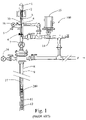
- Lubricator assembly 10 is one of the most important components of plunger system 100 .
- Lubricator assembly 10 includes cap 1 , integral top bumper spring 2 , striking pad 3 , and extracting rod 4 . Extracting rod 4 may or may not be employed depending on the plunger type.
- Contained within lubricator assembly 10 is plunger auto catching device 5 and plunger sensing device 6 .
- Sensing device 6 sends a signal to surface controller 15 upon plunger 200 arrival at the well top.
- Plunger 200 can represent the plunger of the present invention or other prior art plunges. Sensing the plunger is used as a programming input to achieve the desired well production, flow times and wellhead operating pressures.
- Master valve 7 should be sized correctly for the tubing 9 and plunger 200 . An incorrectly sized master valve 7 will not allow plunger 200 to pass through. Master valve 7 should incorporate a full bore opening equal to the tubing 9 size. An oversized valve will allows gas to bypass the plunger causing it to stall in the valve.
- the bottom of a well is typically equipped with a seating nipple/tubing stop 12 .
- Spring standing valve/bottom hole bumper assembly 11 is located near the tubing bottom. The bumper spring is located above the standing valve and can be manufactured as an integral part of the standing valve or as a separate component of the plunger system. Fluid accumulating on top of plunger 200 may be carried to the well top by plunger 200 .
- Surface control equipment usually consists of motor valve(s) 14 , sensors 6 , pressure recorders 16 , etc., and an electronic controller 15 which opens and closes the well at the surface.
- Well flow ‘F’ proceeds downstream when surface controller 15 opens well head flow valves.
- Controllers operate on time, or pressure, to open or close the surface valves based on operator-determined requirements for production.
- Modern electronic controllers incorporate features that are user friendly, easy to program, addressing the shortcomings of mechanical controllers and early electronic controllers. Additional features include: battery life extension through solar panel recharging, computer memory program retention in the event of battery failure and built-in lightning protection. For complex operating conditions, controllers can be purchased that have multiple valve capability to fully automate the production process.
- Plungers use the volume of gas stored in the casing and the formation during the shut-in time to push the liquid load and plunger to the surface when the motor valve opens the well to the sales line or to the atmosphere.
- the pressure and gas volume in the tubing/casing annulus is usually considered as the source of energy for bringing the liquid load and plunger to the surface.
- a plunger lift apparatus whose orifice size can be tuned to well conditions at the well itself and whose orifice size can be quickly changed at the well site as well liquid loading conditions change over time.
- the invention must function in a high liquid well, be one that can insure continuous efficiency during lift, drop back to the well bottom quickly and easily and assist in increasing well production by increasing lift cycle times.
- the apparatus of the present invention provides a solution to these issues.
- One aspect of the present device is to provide a variable orifice by-pass plunger apparatus that can increase well production levels in a high liquid well.
- Another aspect of the present device is to provide a by-pass plunger apparatus with a by-pass orifice that can be easily varied at the well itself to several different positions.
- Another aspect of the present device is to provide a by-pass plunger that could efficiently force fall inside the tubing to the wellhole bottom with increased speed without impeding well production.
- Another aspect of the present device is to allow for a by-pass valve to be shut once the plunger reaches the well bottom in order to provide for proper plunger return lift to the well top.
- Yet another aspect of the present device is to allow for the plunger by-pass valve to be re-opened to its preset condition once the plunger reaches the well top.
- Another aspect of the present device is to allow for various plunger sidewall geometries to be utilized.
- the present device comprises a plunger lift apparatus having a top second with an inner diameter allowing for liquid by-pass, and a bottom second comprising a variable by-pass valve to allow fluid to flow through the valve and up through the top section during the return trip to the bumper spring at the well bottom.
- the device typically comprises an inside top hollow orifice design (typically a standard American Petroleum Institute fishing neck).
- variable orifice by-pass plunger allows more than one orifice setting in the by-pass valve.
- the VOV can be set to optimize the VOBP return time to the well bottom, thus optimizing the production efficiency of the well.
- the VOBP comprises a variable orifice valve (VOV) that has a variable orifice that can easily be set to more than one position.
- VOV variable orifice valve
- an orifice functions to allow liquid to pass through the plunger's lower valve section and up through the plunger's top second during its trip to the well bottom.
- the well control system will release the plunger to fall in the well when conditions are satisfied.
- the lower valve section is designed to shut off the by-pass feature when striking the aforementioned bumper spring.
- the aforementioned extracting rod within the lubricator will cause the device's valve section to re-open at its predetermined set condition.
- the present device helps to assure an efficient lift in a high liquid well due to its design.
- the present device can also optimize well efficiency due to the fact that it has a field-adjustable orifice to allow it to quickly travel to the well bottom.
- FIG. 1 (prior art) is an overview depiction of a typical plunger lift system installation.
- FIG. 2 is a side perspective view of the variable orifice valve (VOV) of the disclosed device.
- VV variable orifice valve
- FIG. 3 is a side perspective exploded view of the device shown in FIG. 2 .
- FIG. 4A is a side cross-sectional view of the disclosed device shown in an open (or bypass) position.
- FIG. 4B is a side cross-sectional view of the disclosed device shown in a closed (no bypass) position.
- FIG. 5 is a top cross sectional view of the FIG. 2 embodiment showing the three ball and spring fixed locations.
- FIG. 6 is a blow up view of a portion of FIGS. 4A , 4 B illustrating a ball and spring combination ratcheted (or set) in a middle location.
- FIGS. 7 , 8 , 9 are side perspective drawings of the disclosed device showing the adjustment of the device to three setpoints.
- FIG. 10 shows side plan views of the disclosed device with various sidewall geometries.
- FIG. 11 is a side plan view of the disclosed device falling through liquid within the well tubing.
- FIG. 12 is an exploded view of an alternate embodiment.
- the disclosed device provides a variable orifice by-pass plunger (VOBP) (see item 1000 of FIG. 11 ) that may help increase well production levels in a high liquid well.
- the VOBP comprises a lower section variable orifice valve (VOV) 200 (see FIGS. 2 , 3 , 4 , 10 ) that can be easily preset to several different levels.
- VV variable orifice valve
- One embodiment comprises three set levels.
- the VOBP is designed to be set to an optimized by-pass orifice opening to efficiently force fall through liquid inside the tubing to the well-hole bottom. Adjustment of the orifice setting seeks to alter return speed through liquid and thus optimize well production.
- VOV 200 comprises an internal by-pass shut off mechanism, which will close the by-pass feature once the plunger reaches the well bottom.
- a shut off condition provides for proper plunger return lift to the well top.
- the plunger by-pass valve will be re-opened to its preset condition once the plunger reaches the well top.
- the top second of a VOBP can be designed using various aforementioned plunger sidewall geometries (ref. FIG. 10 , items 20 , 60 , 70 , 80 ) each comprising a hollowed out core 47 .
- the top collar of each VOBP illustrated is designed with a standard American Petroleum Institute (API) internal fishing neck. Fish necks are a well-known industrial design offering and are therefore not shown in detail herein.
- API American Petroleum Institute
- a spring loaded ball within a retriever and protruding outside the retriever's surface falls within the API internal fishing neck if retrieval is necessary.
- VOV 200 attaches to the VOBP top section.
- VOV 200 comprises a variable by-pass orifice to allow fluid to flow through the VOV and up through the top section during the plunger's trip to the bumper spring at the well bottom.
- the disclosed device allows more than one orifice opening setting within VOV 200 . That is, the variable orifice can easily be set to one or more positions. When released from the auto catcher, the orifice will function to allow liquid W (ref. FIG. 11 ) to pass through the lower section (VOV 200 ) and up through hollowed out core 47 (see FIGS. 10 , 11 ) during its trip to the well bottom. The well control system will release the VOBP to fall into the well when conditions are satisfied.
- VOV 200 can be set to optimize the plunger's travel time to the well bottom, thus optimizing the production efficiency of the well. Once at the well bottom, the VOV is designed to strike the aforementioned bumper spring and close. Upon its trip to the well top, the aforementioned extracting rod within the lubricator will cause VOV 200 to reopen at its predetermined set condition.
- the disclosed device comprises an adjustable orifice to allow it to quickly travel to the well bottom.
- the orifice is thus field adjustable; it can be tuned at the well site depending on well parameters to optimize well cycle times. The higher the well pressure and/or liquid loading, the greater the orifice opening can be set. This results in the ability to optimize the bypass settings based on well conditions allowing the VOBP to fall to the bottom in an optimal manner. This avoids having to have a variety of different bypass valves, with various manufactured orifice openings, at the well site.
- the VOBP disclosed herein provides for the ability to field-adjust the bypass settings as well parameters change over time.
- the VOBP may be employed as follows:
- FIG. 2 is a side perspective view of VOV 200 .
- VOV 200 is located at the bottom section of the VOBP. When the VOBP falls to the well bottom, push rod 25 bottom surface 34 will strike the aforementioned well bottom bumper spring causing push rod 25 to move up into VOV 200 and close the bypass function (ref. FIG. 4B ).
- VOV 200 is shown with VOV body cylinder 40 having VOV body cylinder orifice 43 set to one-third open due to the position of variable control cylinder 26 . The positioning of variable control cylinder 26 can be adjusted through adjustment slot 29 .
- VOV bottom cap 24 functions to contain all internal parts of VOV 200 .
- FIG. 12 A drawing of an alternate embodiment ( FIG. 12 ) shows the upper body end 440 securing the control cylinder 2600 in a fixed position.
- the VOV body cylinder 4000 rotates around the upper body end 440 . Threads could provide this rotation, cylinder pins 4011 could mount in holes 4010 in the body end 440 , or other design choices could be used.
- the slots 4015 are ajustably aligned with slots 4016 to provide a variable orifice. Hole 4020 can be aligned with a chosen hole 4010 to set the orifice.
- Sheath 441 secures the cylinder 4000 to the upper body end 440 .
- FIG. 3 is a side perspective exploded view of VOV 200 .
- VOV body cylinder 40 is designed to have an adjustment slot 29 for orifice adjustment access. Adjustment slot 29 provides tool 38 with access to control cylinder adjustment hole 32 .
- VOV body cylinder orifices 43 are shown spaced at about 90° apart.
- Internal threaded lower body end 20 A accepts VOV bottom cap 24 .
- VOV bottom cap 24 comprises external threaded area 24 A mateable with VOV body cylinder internal threaded lower body end 20 A.
- Internal wall 3 (ref. FIGS. 5 , 6 ) can comprise three springs 27 and three corresponding balls 28 all with a fixed position and separated by about 120°.
- Internal threaded upper body end 44 mates with threaded end 41 (see FIG. 10 ) of a plunger.
- Push rod brake clutch 21 comprises two half cylinders 23 each containing annular grooves to contain annular push rod brake clutch springs 23 and functioning to contain push rod 25 in either its open or closed positions.
- Bottom bumper striker end 34 can move push rod 25 into a closed position once VOBP hits the well bottom.
- Push rod closure end 37 , outer closure ring 35 and rod slant surface 36 function to both close against VOBP top second at the well bottom and also to move to an open position when VOBP lifts to the well top.
- the striker rod within the lubricator (not shown) will strike against rod top end 37 to move push rod 25 into its open position thus allowing the VOBP to bypass fluids on its travel to the well bottom.
- Variable control cylinder 26 comprises external adjustment hole 32 and four control cylinder orifices 31 which are spaced apart by about 90°.
- Variable control cylinder top source 46 shows nine preset position control half globe holes 33 located in groups of three, each group about 120° apart and each half globeholes within a group at about 20° apart.
- Control half globe holes 33 mate with balls 28 three at a time providing three preset through-orifice positions (full open, one-third open, two thirds open) in each of the four through orifices.
- the total opening, or through-orifice is a function of the position of the control cylinder orifices 31 with respect to the VOV body cylinder orifices 43 .
- VOV 200 When VOV 200 is assembled, control cylinder orifices 31 align with VOV main body cylinder orifices 43 such that the total through opening will be about 33%, 67%, or 100% depending on the positioning of variable control cylinder 26 in one of its three set positions. Adjustment slot 29 provides external tool 38 right movement direction TR or left movement direction TL functioning to set variable control cylinder 26 in one of its three positions via control cylinder adjustment control hole 32 .
- VOV 200 is geometrically designed to have a fluid/gas dynamic type shape to allow it to quickly pass to the well bottom while allowing fluids to enter its orifice and pass through the top bored out section of the VOBP. Thus the VOBP will travel to the bottom with an efficient speed until it comes to rest on the bottom sitting or on a bumper spring, which will strike its push rod and close its bypass function.
- FIG. 4A is a side cross-sectional view of VOV 200 showing push rod 25 in the open (or bypass) position. Threaded upper body end 44 mates with threaded end 41 (ref. FIG. 10 ).
- VOV 200 arrives at the well top, the aforementioned striker rod within the lubricator hits push rod 25 at rod top end 37 moving push rod 25 in direction P to its open position. In its open position, the top end of push rod 25 rests against variable control cylinder 26 internal surface. Brake clutch 21 will hold push rod 25 in its open position allowing well loading (gas/fluids etc.) to enter the open orifice and move up through top second center bore 45 .
- FIG. 4B is a side cross-sectional view of VOV 200 with push rod 25 depicted in its closed (no bypass) position.
- push rod 25 moves in direction C to a closed position as shown.
- rod top end 37 with its slant surface 36 closes against threaded top section end 44 and is held in the closed position by brake clutch 21 .
- FIG. 5 is a top cross-sectional view of (ref. section 5 - 5 of FIGS. 3 , 4 A, 4 B) VOV body cylinder 40 showing three ball and spring fixed locations.
- Three ball springs 27 and three balls 28 (ref. FIG. 3 ) are located within bored out holes 4 spaced in an annular position around inner wall 3 and about 120° apart.
- FIG. 6 is a blow up view showing inner variable control cylinder top surface 46 rarcheted (or set) in a middle orifice bypass set location. That is, of the possible three preset control half holes 33 within variable control cylinder top surface 46 locations, the through orifice is set to the mid bypass location. Thus shown is one of the three ball springs 27 , and ball 28 located within one of the fixed internal set holes 4 . Movement of variable control cylinder 26 (ref. FIG. 3 ) is in either direction TR or TL, which ratchets and fixes the bypass total through-orifice opening to a set location.
- FIGS. 7 , 8 , 9 are side perspective drawings of VOV 200 showing the adjustment of the device to three possible VOV locations of the preferred embodiment.
- FIG. 7 depicts external tool 38 within adjustment slot 29 and in leftmost position P 1 .
- variable control cylinder orifice is aligned with the VOV body cylinder orifice such that the through orifice is in fully open position 50 .
- FIG. 8 depicts movement of external tool 38 in direction TR to mid-point P 2 setting. In this mid-point P 2 setting, the through orifice is now at two-thirds open position 51 .
- FIG. 9 depicts further movement of external tool 38 in direction TR to its rightmost position P 3 , which has the through orifice in its one-third open position.
- FIG. 10 shows side views of various VOBPs each utilizing a different sidewall geometry.
- Each VOBP is depicted in an unassembled state with respect to its unique sidewall geometry top section and a common VOV 200 bottom section.
- Each top section typically employs a standard API internal fishing neck.
- Each top section also has hollowed out core 47 .
- Each bottom section shown depicts VOV 200 shown in its full open (or full bypass) set position.
- Each VOV 200 has internal threaded end 44 , which accepts top second threaded end 41 to unite both sections. Shown in FIG. 10 are VOBPs with the following geometries:
- FIG. 11 is a side plan view of VOBP 1000 falling, in direction F, through liquid W within the well tubing 9 .
- VOBP 1000 is shown fully assembled with a solid sidewall top section 20 (ref. FIG. 10 ) and bottom section VOV 200 (ref. FIGS. 2 , 3 , 4 ) that is set in to a full open position.
- Liquid W enters VOV body cylinder orifice 43 , moves up through hollowed out core 47 in direction D and out through VOBP 1000 top section 20 .
- VOBP 1000 thus moves through liquid within well tubing 9 and outer casing 8 in an efficient manner with VOV body orifice 43 set to an optimum opening position.
- the disclosed device allows for initial bypass tuning at the well site, allows future resets if necessary within one single plunger, and thus can assure well production optimization in high liquid gas wells.
- variable orifice valve VOV
- adjustment mechanisms to set the orifice openings (such as ratchet type adjustments etc.), various orifice opening settings, orifice geometric design other than those described above, and various internal part designs contained therein.
Abstract
Description
-
- A. Shifting ring plungers for continuous contact against the tubing to produce an effective seal with wiping action to ensure that all scale, salt and paraffin is removed from the tubing wall. Some designs have by-pass valves to permit fluid to flow through during the return trip to the bumper spring with the by-pass shutting when the plunger reaches the bottom. The by-pass feature optimizes plunger travel time in high liquid wells.
- B. Pad plungers have spring-loaded interlocking pads in one or more sections. The pads expand and contract to compensate for any irregularities in the tubing, thus creating a tight friction seal. Pad plungers can also have a by-pass valve as described above.
- C. Brush plungers incorporate a spiral-wound, flexible nylon brush section to create a seal and allow the plunger to travel despite the presence of sand, coal fines, tubing irregularities, etc. By-pass valves may also be incorporated.
- D. Solid plunger have solid sidewall rings for durability. Solid sidewall rings can be made of various materials such as steel, poly materials, Teflon, stainless steel, etc. Once again, by-pass valves can be incorporated.
- E. Snake plungers are flexible for coiled tubing and directional holes, and can be used as well in straight standard tubing.
-
- The pressure of the gas in the casing pushes up on the liquid load and the plunger.
- The sales line operating pressure and atmospheric pressure push down on the plunger.
- The weight of the liquid and the plunger weight push down on the plunger.
- Once the plunger begins moving to the surface, friction between the tubing and the liquid load acts to oppose the plunger.
- In addition, friction between the gas and tubing acts to slow the expansion of the gas.
-
- 1. The bypass setting is manually tuned for well loading conditions (ref.
FIGS. 7 , 8, 9). - 2. The VOBP is at the bottom of a well with liquid loading on top of the plunger and with its
push rod 25 set in a closed bypass position (ref.FIG. 4B ). - 3. The well is open for flow at which time the VOBP rises towards the well top to carry accumulated liquids out of the well bore.
- 4. The VOBP reaches the well top, is caught within the lubricator, and the extracting rod (ref.
FIG. 1 ) strikes pushrod 25 to move it into a bypass (or open) position (ref.FIG. 4A ). - 5. The well flows for a set time or condition controlled by the well-head controller.
- 6. The auto-catcher releases the VOBP after a set time or condition as controlled by the well system controller.
- 7. The VOBP force falls to the well bottom, its bypass setting allowing liquid enter its bypass opening and regulate its fall to the well bottom.
- 8. The well plunger lift cycle starts again (
step 2 above). - 9. Periodically, an operator visits the well site and decides whether or not to change the bypass setting for sizing the flow through orifice, depending on the well liquid loading parameters.
- 1. The bypass setting is manually tuned for well loading conditions (ref.
-
- a)
VOBP 300 with top second 60 having spring-loadedinterlocking pads 61 in one or more sections. The pads expand and contract to compensate for any irregularities in the tubing thus creating a tight friction seal. - b)
VOBP 400 havingtop section 70 withbrush sidewall 71 which is a spiral-wound, flexible nylon brush section to create a seal and allow theVOBP 400 to travel despite the presence of sand, coal fined, tubing irregularities, etc - c) VOBP 500 having
top section 20 with solid sidewall rings 22 and cutgrooves 30 for durability. Solid sidewall rings can be made of various materials such as steel, poly materials, Teflon®, stainless steel, etc. - d)
VOVP 600 havingtop section 80 with shiftingrings 81 individually separated at each upper surface and lower surface byair gap 82 for continuous contact against the tubing to produce an effective seal with wiping action to ensure that all scale, salt or paraffin is removed from the tubing wall.
- a)
Claims (19)
Priority Applications (1)
| Application Number | Priority Date | Filing Date | Title |
|---|---|---|---|
| US11/110,447 US7438125B2 (en) | 2004-04-20 | 2005-04-20 | Variable orifice bypass plunger |
Applications Claiming Priority (2)
| Application Number | Priority Date | Filing Date | Title |
|---|---|---|---|
| US56371104P | 2004-04-20 | 2004-04-20 | |
| US11/110,447 US7438125B2 (en) | 2004-04-20 | 2005-04-20 | Variable orifice bypass plunger |
Publications (2)
| Publication Number | Publication Date |
|---|---|
| US20050241819A1 US20050241819A1 (en) | 2005-11-03 |
| US7438125B2 true US7438125B2 (en) | 2008-10-21 |
Family
ID=35185901
Family Applications (1)
| Application Number | Title | Priority Date | Filing Date |
|---|---|---|---|
| US11/110,447 Expired - Fee Related US7438125B2 (en) | 2004-04-20 | 2005-04-20 | Variable orifice bypass plunger |
Country Status (1)
| Country | Link |
|---|---|
| US (1) | US7438125B2 (en) |
Cited By (31)
| Publication number | Priority date | Publication date | Assignee | Title |
|---|---|---|---|---|
| US20110232765A1 (en) * | 2010-03-25 | 2011-09-29 | Baker Hughes Incorporated | Valving device and method |
| US8464798B2 (en) | 2010-04-14 | 2013-06-18 | T-Ram Canada, Inc. | Plunger for performing artificial lift of well fluids |
| US8764406B2 (en) | 2010-10-04 | 2014-07-01 | William K. Filippi | Fluid level control mechanism |
| US8764407B2 (en) | 2010-10-04 | 2014-07-01 | William K. Filippi | Fluid level control mechanism |
| US8863828B1 (en) * | 2009-11-04 | 2014-10-21 | George Thomas Strong | Stripper device with retrieval mounting portion and method of use |
| US9068443B2 (en) | 2012-10-31 | 2015-06-30 | Epic Lift Systems Llc | Plunger lift apparatus |
| US9109424B2 (en) | 2013-06-28 | 2015-08-18 | Epic Lift Systems Llc | Gas lift plunger |
| US20150275633A1 (en) * | 2014-03-26 | 2015-10-01 | Randy C. Tolman | Selectively Actuated Plungers and Systems and Methods Including the Same |
| USD767737S1 (en) * | 2015-02-27 | 2016-09-27 | Epic Lift Systems Llc | Gas lift plunger with curved, undercut grooves |
| US9470073B2 (en) | 2012-06-05 | 2016-10-18 | Saudi Arabian Oil Company | Downhole fluid transport plunger with motor and propeller and associated method |
| US9689242B2 (en) | 2012-10-31 | 2017-06-27 | Epic Lift Systems Llc | Dart plunger |
| US20170183946A1 (en) * | 2015-12-28 | 2017-06-29 | Randy C. Tolman | Actuatable Plungers with Actuatable External Seals, and Systems and Methods Including the Same |
| US9915133B2 (en) | 2015-02-20 | 2018-03-13 | Flowco Production Solutions, LLC | Unibody bypass plunger with centralized helix and crimple feature |
| US9951591B2 (en) | 2014-07-11 | 2018-04-24 | Flowco Production Solutions, LLC | Bypass plunger |
| US10006274B2 (en) | 2014-08-28 | 2018-06-26 | Superior Energy Services, L.L.C. | Durable dart plunger |
| US10060235B2 (en) | 2015-08-25 | 2018-08-28 | Eog Resources, Inc. | Plunger lift systems and methods |
| US10161231B2 (en) | 2015-09-08 | 2018-12-25 | William Charles Harris | Plunger lift with internal movable element |
| WO2019173531A1 (en) * | 2018-03-06 | 2019-09-12 | Flowco Production Solutions, LLC | Unibody bypass plunger and valve cage with sealable ports |
| US10550674B2 (en) | 2018-03-06 | 2020-02-04 | Flowco Production Solutions, LLC | Internal valve plunger |
| US10570674B1 (en) * | 2018-08-30 | 2020-02-25 | Black Gold Pump And Supply, Inc. | Rod string latching tool without integral release mechanism and method for use of same |
| US10669824B2 (en) | 2015-02-20 | 2020-06-02 | Flowco Production Solutions, LLC | Unibody bypass plunger and valve cage with sealable ports |
| US10677027B2 (en) | 2015-01-15 | 2020-06-09 | Flowco Production Solutions, LLC | Apparatus and method for securing end pieces to a mandrel |
| US10718327B2 (en) | 2015-05-18 | 2020-07-21 | Patriot Artificial Lift, LLC | Forged flange lubricator |
| US10895128B2 (en) | 2019-05-22 | 2021-01-19 | Pcs Ferguson, Inc. | Taper lock bypass plunger |
| US10907452B2 (en) | 2016-03-15 | 2021-02-02 | Patriot Artificial Lift, LLC | Well plunger systems |
| US11180965B2 (en) * | 2019-06-13 | 2021-11-23 | China Petroleum & Chemical Corporation | Autonomous through-tubular downhole shuttle |
| US11180977B2 (en) | 2015-09-08 | 2021-11-23 | William Charles Harris | Plunger lift method |
| USD937982S1 (en) | 2019-05-29 | 2021-12-07 | Flowco Production Solutions, LLC | Apparatus for a plunger system |
| US11293267B2 (en) | 2018-11-30 | 2022-04-05 | Flowco Production Solutions, LLC | Apparatuses and methods for scraping |
| US11326424B2 (en) * | 2015-01-15 | 2022-05-10 | Flowco Production Solutions, LLC | Apparatus and method for securing end pieces to a mandrel |
| US11448049B2 (en) | 2019-09-05 | 2022-09-20 | Flowco Production Solutions, LLC | Gas assisted plunger lift control system and method |
Families Citing this family (19)
| Publication number | Priority date | Publication date | Assignee | Title |
|---|---|---|---|---|
| US7690425B2 (en) * | 2004-02-18 | 2010-04-06 | Production Control Services, Inc. | Data logger plunger and method for its use |
| US7314080B2 (en) * | 2005-12-30 | 2008-01-01 | Production Control Services, Inc. | Slidable sleeve plunger |
| US7954545B2 (en) * | 2008-01-25 | 2011-06-07 | Weatherford/Lamb, Inc. | Plunger lift system for well |
| US9976548B2 (en) | 2014-08-28 | 2018-05-22 | Superior Energy Services, L.L.C. | Plunger lift assembly with an improved free piston assembly |
| US9869165B2 (en) * | 2014-10-15 | 2018-01-16 | Well Master Corp | Plunger lift arrangement |
| US20160168963A1 (en) * | 2014-12-15 | 2016-06-16 | Patriot Artificial Lift, LLC | Bypass dart and assembly |
| US11578570B2 (en) * | 2015-02-20 | 2023-02-14 | Flowco Production Solutions, LLC | Unibody bypass plunger and valve cage with sealable ports |
| CA2921175C (en) * | 2015-02-20 | 2023-09-26 | Flowco Production Solutions, LLC | Improved dart valves for bypass plungers |
| US9677389B2 (en) | 2015-08-25 | 2017-06-13 | Flowco Production Solutions, LLC | Dart valve assembly for a bypass plunger |
| US10378321B2 (en) | 2016-06-10 | 2019-08-13 | Well Master Corporation | Bypass plungers including force dissipating elements and methods of using the same |
| US9957784B1 (en) | 2016-10-26 | 2018-05-01 | Flowco Production Solutions, LLC | Latch for a ball and sleeve plunger |
| US9869401B1 (en) | 2016-10-28 | 2018-01-16 | Flowco Production Solutions, LLC | Split bobbin clutch for bypass plungers |
| US20220056785A1 (en) * | 2018-09-13 | 2022-02-24 | Flowco Production Solutions, LLC | Unibody bypass plunger with integral dart valve cage |
| CN111927362A (en) * | 2020-08-04 | 2020-11-13 | 中国石油天然气股份有限公司 | Plunger gas well electric intelligent capturing plunger device and using method thereof |
| US11629710B2 (en) * | 2020-10-08 | 2023-04-18 | Pcs Ferguson, Inc. | Torpedo plunger |
| CN113719259B (en) * | 2021-06-25 | 2022-07-22 | 西安石油大学 | Gas lift intelligence helping hand plunger |
| US20230008526A1 (en) * | 2021-07-09 | 2023-01-12 | Kaizen Well Solutions Ltd. | Radial flow plunger lift lubricator |
| CN114645696B (en) * | 2022-03-14 | 2024-01-30 | 宝鸡文理学院 | Hybrid gas lift plunger |
| CN115263254B (en) * | 2022-08-15 | 2023-07-14 | 陈彦洪 | Articulated ratchet flow adjustable layering oil pumping device |
Citations (31)
| Publication number | Priority date | Publication date | Assignee | Title |
|---|---|---|---|---|
| US2147766A (en) | 1937-04-21 | 1939-02-21 | Roko Corp | Fluid-operated pump piston device |
| US2714855A (en) | 1952-05-01 | 1955-08-09 | N F B Displacement Co Ltd | Apparatus for gas lift of liquid in wells |
| US3181470A (en) | 1963-09-03 | 1965-05-04 | Walter L Clingman | Gas lift plunger |
| US3861471A (en) | 1973-09-17 | 1975-01-21 | Dresser Ind | Oil well pump having gas lock prevention means and method of use thereof |
| US4502843A (en) | 1980-03-31 | 1985-03-05 | Noodle Corporation | Valveless free plunger and system for well pumping |
| US4712981A (en) | 1986-02-24 | 1987-12-15 | Gramling William D | Pressure-operated valving for oil and gas well swabs |
| US5253713A (en) | 1991-03-19 | 1993-10-19 | Belden & Blake Corporation | Gas and oil well interface tool and intelligent controller |
| US5333684A (en) | 1990-02-16 | 1994-08-02 | James C. Walter | Downhole gas separator |
| US5431229A (en) | 1994-01-13 | 1995-07-11 | Reaction Oilfield Products Ltd. | Method and apparatus for utilizing the pressure of a fluid column generated by a pump to assist in reciprocating the pump plunger |
| US6148923A (en) | 1998-12-23 | 2000-11-21 | Casey; Dan | Auto-cycling plunger and method for auto-cycling plunger lift |
| US6176309B1 (en) | 1998-10-01 | 2001-01-23 | Robert E. Bender | Bypass valve for gas lift plunger |
| US6273690B1 (en) | 1999-06-25 | 2001-08-14 | Harbison-Fischer Manufacturing Company | Downhole pump with bypass around plunger |
| US6325152B1 (en) | 1996-12-02 | 2001-12-04 | Kelley & Sons Group International, Inc. | Method and apparatus for increasing fluid recovery from a subterranean formation |
| US6467541B1 (en) | 1999-05-14 | 2002-10-22 | Edward A. Wells | Plunger lift method and apparatus |
| US20020162662A1 (en) | 2001-03-05 | 2002-11-07 | Passamaneck Richard S. | System for lifting water from gas wells using a propellant |
| US6543543B2 (en) | 1994-10-20 | 2003-04-08 | Muth Pump Llc | Pump systems and methods |
| US6554580B1 (en) | 2001-08-03 | 2003-04-29 | Paal, L.L.C. | Plunger for well casings and other tubulars |
| US6591737B2 (en) | 2000-09-27 | 2003-07-15 | Jeff Giacomino | Pad plunger assembly with interfitting keys and key ways on mandrel and pads |
| US20030141051A1 (en) | 2002-01-25 | 2003-07-31 | Synco Tool Company Incorporated | Water, oil and gas well recovery system |
| US20030155129A1 (en) | 2002-02-15 | 2003-08-21 | Gray William R. | Plunger with novel sealing |
| US6637510B2 (en) | 2001-08-17 | 2003-10-28 | Dan Lee | Wellbore mechanism for liquid and gas discharge |
| US20030215337A1 (en) | 2002-04-18 | 2003-11-20 | Dan Lee | Wellbore pump |
| US6669449B2 (en) | 2001-08-27 | 2003-12-30 | Jeff L. Giacomino | Pad plunger assembly with one-piece locking end members |
| RU2225502C1 (en) | 2002-06-25 | 2004-03-10 | Грабовецкий Владимир Леонидович | Method for extracting gas and fluid from the well and sucker-rod well pump implementing said method |
| US6705404B2 (en) | 2001-09-10 | 2004-03-16 | Gordon F. Bosley | Open well plunger-actuated gas lift valve and method of use |
| US6725916B2 (en) | 2002-02-15 | 2004-04-27 | William R. Gray | Plunger with flow passage and improved stopper |
| US6746213B2 (en) | 2001-08-27 | 2004-06-08 | Jeff L. Giacomino | Pad plunger assembly with concave pad subassembly |
| US20040129428A1 (en) | 2002-12-20 | 2004-07-08 | Kelley Terry Earl | Plunger lift deliquefying system for increased recovery from oil and gas wells |
| CA2428618A1 (en) | 2003-05-13 | 2004-11-13 | Murray Ray Townsend | Plunger for gas wells |
| US20050194149A1 (en) * | 2004-03-03 | 2005-09-08 | Giacomino Jeffrey L. | Thermal actuated plunger |
| US6945762B2 (en) | 2002-05-28 | 2005-09-20 | Harbison-Fischer, Inc. | Mechanically actuated gas separator for downhole pump |
-
2005
- 2005-04-20 US US11/110,447 patent/US7438125B2/en not_active Expired - Fee Related
Patent Citations (32)
| Publication number | Priority date | Publication date | Assignee | Title |
|---|---|---|---|---|
| US2147766A (en) | 1937-04-21 | 1939-02-21 | Roko Corp | Fluid-operated pump piston device |
| US2714855A (en) | 1952-05-01 | 1955-08-09 | N F B Displacement Co Ltd | Apparatus for gas lift of liquid in wells |
| US3181470A (en) | 1963-09-03 | 1965-05-04 | Walter L Clingman | Gas lift plunger |
| US3861471A (en) | 1973-09-17 | 1975-01-21 | Dresser Ind | Oil well pump having gas lock prevention means and method of use thereof |
| US4502843A (en) | 1980-03-31 | 1985-03-05 | Noodle Corporation | Valveless free plunger and system for well pumping |
| US4712981A (en) | 1986-02-24 | 1987-12-15 | Gramling William D | Pressure-operated valving for oil and gas well swabs |
| US5333684A (en) | 1990-02-16 | 1994-08-02 | James C. Walter | Downhole gas separator |
| US5253713A (en) | 1991-03-19 | 1993-10-19 | Belden & Blake Corporation | Gas and oil well interface tool and intelligent controller |
| US5431229A (en) | 1994-01-13 | 1995-07-11 | Reaction Oilfield Products Ltd. | Method and apparatus for utilizing the pressure of a fluid column generated by a pump to assist in reciprocating the pump plunger |
| US6543543B2 (en) | 1994-10-20 | 2003-04-08 | Muth Pump Llc | Pump systems and methods |
| US6325152B1 (en) | 1996-12-02 | 2001-12-04 | Kelley & Sons Group International, Inc. | Method and apparatus for increasing fluid recovery from a subterranean formation |
| US6176309B1 (en) | 1998-10-01 | 2001-01-23 | Robert E. Bender | Bypass valve for gas lift plunger |
| US6148923A (en) | 1998-12-23 | 2000-11-21 | Casey; Dan | Auto-cycling plunger and method for auto-cycling plunger lift |
| US6467541B1 (en) | 1999-05-14 | 2002-10-22 | Edward A. Wells | Plunger lift method and apparatus |
| US6273690B1 (en) | 1999-06-25 | 2001-08-14 | Harbison-Fischer Manufacturing Company | Downhole pump with bypass around plunger |
| US6591737B2 (en) | 2000-09-27 | 2003-07-15 | Jeff Giacomino | Pad plunger assembly with interfitting keys and key ways on mandrel and pads |
| US20020162662A1 (en) | 2001-03-05 | 2002-11-07 | Passamaneck Richard S. | System for lifting water from gas wells using a propellant |
| US6554580B1 (en) | 2001-08-03 | 2003-04-29 | Paal, L.L.C. | Plunger for well casings and other tubulars |
| US6637510B2 (en) | 2001-08-17 | 2003-10-28 | Dan Lee | Wellbore mechanism for liquid and gas discharge |
| US6746213B2 (en) | 2001-08-27 | 2004-06-08 | Jeff L. Giacomino | Pad plunger assembly with concave pad subassembly |
| US6669449B2 (en) | 2001-08-27 | 2003-12-30 | Jeff L. Giacomino | Pad plunger assembly with one-piece locking end members |
| US6907926B2 (en) | 2001-09-10 | 2005-06-21 | Gordon F. Bosley | Open well plunger-actuated gas lift valve and method of use |
| US6705404B2 (en) | 2001-09-10 | 2004-03-16 | Gordon F. Bosley | Open well plunger-actuated gas lift valve and method of use |
| US20030141051A1 (en) | 2002-01-25 | 2003-07-31 | Synco Tool Company Incorporated | Water, oil and gas well recovery system |
| US20030155129A1 (en) | 2002-02-15 | 2003-08-21 | Gray William R. | Plunger with novel sealing |
| US6725916B2 (en) | 2002-02-15 | 2004-04-27 | William R. Gray | Plunger with flow passage and improved stopper |
| US20030215337A1 (en) | 2002-04-18 | 2003-11-20 | Dan Lee | Wellbore pump |
| US6945762B2 (en) | 2002-05-28 | 2005-09-20 | Harbison-Fischer, Inc. | Mechanically actuated gas separator for downhole pump |
| RU2225502C1 (en) | 2002-06-25 | 2004-03-10 | Грабовецкий Владимир Леонидович | Method for extracting gas and fluid from the well and sucker-rod well pump implementing said method |
| US20040129428A1 (en) | 2002-12-20 | 2004-07-08 | Kelley Terry Earl | Plunger lift deliquefying system for increased recovery from oil and gas wells |
| CA2428618A1 (en) | 2003-05-13 | 2004-11-13 | Murray Ray Townsend | Plunger for gas wells |
| US20050194149A1 (en) * | 2004-03-03 | 2005-09-08 | Giacomino Jeffrey L. | Thermal actuated plunger |
Non-Patent Citations (1)
| Title |
|---|
| MGM Well Service, Inc., Pacemaker Plunger Co., P.O. Box, 270924, Corpus Christi, TX 78427-0924 Pacemaker Plunger Cariations internet marketing material, Feb. 12, 2003. |
Cited By (41)
| Publication number | Priority date | Publication date | Assignee | Title |
|---|---|---|---|---|
| US8863828B1 (en) * | 2009-11-04 | 2014-10-21 | George Thomas Strong | Stripper device with retrieval mounting portion and method of use |
| US20110232765A1 (en) * | 2010-03-25 | 2011-09-29 | Baker Hughes Incorporated | Valving device and method |
| US8464798B2 (en) | 2010-04-14 | 2013-06-18 | T-Ram Canada, Inc. | Plunger for performing artificial lift of well fluids |
| US8627892B2 (en) | 2010-04-14 | 2014-01-14 | T-Ram Canada, Inc. | Plunger for performing artificial lift of well fluids |
| US8764406B2 (en) | 2010-10-04 | 2014-07-01 | William K. Filippi | Fluid level control mechanism |
| US8764407B2 (en) | 2010-10-04 | 2014-07-01 | William K. Filippi | Fluid level control mechanism |
| US9470073B2 (en) | 2012-06-05 | 2016-10-18 | Saudi Arabian Oil Company | Downhole fluid transport plunger with motor and propeller and associated method |
| US9068443B2 (en) | 2012-10-31 | 2015-06-30 | Epic Lift Systems Llc | Plunger lift apparatus |
| US9689242B2 (en) | 2012-10-31 | 2017-06-27 | Epic Lift Systems Llc | Dart plunger |
| US9790772B2 (en) | 2012-10-31 | 2017-10-17 | Epic Lift Systems Llc | Plunger lift apparatus |
| US9109424B2 (en) | 2013-06-28 | 2015-08-18 | Epic Lift Systems Llc | Gas lift plunger |
| US20150275633A1 (en) * | 2014-03-26 | 2015-10-01 | Randy C. Tolman | Selectively Actuated Plungers and Systems and Methods Including the Same |
| US9976399B2 (en) * | 2014-03-26 | 2018-05-22 | Exxonmobil Upstream Research Company | Selectively actuated plungers and systems and methods including the same |
| US9951591B2 (en) | 2014-07-11 | 2018-04-24 | Flowco Production Solutions, LLC | Bypass plunger |
| US10006274B2 (en) | 2014-08-28 | 2018-06-26 | Superior Energy Services, L.L.C. | Durable dart plunger |
| US11326424B2 (en) * | 2015-01-15 | 2022-05-10 | Flowco Production Solutions, LLC | Apparatus and method for securing end pieces to a mandrel |
| US10677027B2 (en) | 2015-01-15 | 2020-06-09 | Flowco Production Solutions, LLC | Apparatus and method for securing end pieces to a mandrel |
| US9915133B2 (en) | 2015-02-20 | 2018-03-13 | Flowco Production Solutions, LLC | Unibody bypass plunger with centralized helix and crimple feature |
| US9963957B2 (en) | 2015-02-20 | 2018-05-08 | Flowco Production Solutions, LLC | Clutch assembly for bypass plungers |
| US11401789B2 (en) | 2015-02-20 | 2022-08-02 | Flowco Production Solutions, LLC | Unibody bypass plunger and valve cage with sealable ports |
| US10669824B2 (en) | 2015-02-20 | 2020-06-02 | Flowco Production Solutions, LLC | Unibody bypass plunger and valve cage with sealable ports |
| US10273789B2 (en) | 2015-02-20 | 2019-04-30 | Flowco Production Solutions, LLC | Dart valves for bypass plungers |
| US11105189B2 (en) | 2015-02-20 | 2021-08-31 | Flowco Production Solutions, LLC | Unibody bypass plunger and valve cage |
| USD767737S1 (en) * | 2015-02-27 | 2016-09-27 | Epic Lift Systems Llc | Gas lift plunger with curved, undercut grooves |
| US10718327B2 (en) | 2015-05-18 | 2020-07-21 | Patriot Artificial Lift, LLC | Forged flange lubricator |
| US10060235B2 (en) | 2015-08-25 | 2018-08-28 | Eog Resources, Inc. | Plunger lift systems and methods |
| US10161231B2 (en) | 2015-09-08 | 2018-12-25 | William Charles Harris | Plunger lift with internal movable element |
| US10641072B2 (en) | 2015-09-08 | 2020-05-05 | William Charles Harris | Plunger lift method and apparatus |
| US11555386B2 (en) | 2015-09-08 | 2023-01-17 | William Charles Harris | Plunger lift |
| US11180977B2 (en) | 2015-09-08 | 2021-11-23 | William Charles Harris | Plunger lift method |
| US20170183946A1 (en) * | 2015-12-28 | 2017-06-29 | Randy C. Tolman | Actuatable Plungers with Actuatable External Seals, and Systems and Methods Including the Same |
| US10907452B2 (en) | 2016-03-15 | 2021-02-02 | Patriot Artificial Lift, LLC | Well plunger systems |
| US10927652B2 (en) | 2018-03-06 | 2021-02-23 | Flowco Production Solutions, LLC | Internal valve plunger |
| US10550674B2 (en) | 2018-03-06 | 2020-02-04 | Flowco Production Solutions, LLC | Internal valve plunger |
| WO2019173531A1 (en) * | 2018-03-06 | 2019-09-12 | Flowco Production Solutions, LLC | Unibody bypass plunger and valve cage with sealable ports |
| US10570674B1 (en) * | 2018-08-30 | 2020-02-25 | Black Gold Pump And Supply, Inc. | Rod string latching tool without integral release mechanism and method for use of same |
| US11293267B2 (en) | 2018-11-30 | 2022-04-05 | Flowco Production Solutions, LLC | Apparatuses and methods for scraping |
| US10895128B2 (en) | 2019-05-22 | 2021-01-19 | Pcs Ferguson, Inc. | Taper lock bypass plunger |
| USD937982S1 (en) | 2019-05-29 | 2021-12-07 | Flowco Production Solutions, LLC | Apparatus for a plunger system |
| US11180965B2 (en) * | 2019-06-13 | 2021-11-23 | China Petroleum & Chemical Corporation | Autonomous through-tubular downhole shuttle |
| US11448049B2 (en) | 2019-09-05 | 2022-09-20 | Flowco Production Solutions, LLC | Gas assisted plunger lift control system and method |
Also Published As
| Publication number | Publication date |
|---|---|
| US20050241819A1 (en) | 2005-11-03 |
Similar Documents
| Publication | Publication Date | Title |
|---|---|---|
| US7438125B2 (en) | Variable orifice bypass plunger | |
| US7290602B2 (en) | Internal shock absorber bypass plunger | |
| CA2546104C (en) | Liquid aeration plunger | |
| CA2567524C (en) | Slidable sleeve plunger | |
| US6725916B2 (en) | Plunger with flow passage and improved stopper | |
| US20050230120A1 (en) | Sand plunger | |
| CA2592839C (en) | Well production optimizing system | |
| US6209637B1 (en) | Plunger lift with multipart piston and method of using the same | |
| US6045335A (en) | Differential pressure operated free piston for lifting well fluids | |
| US7328748B2 (en) | Thermal actuated plunger | |
| CA2908513C (en) | Two-piece plunger | |
| US20060124292A1 (en) | Internal shock absorber plunger | |
| US20030155129A1 (en) | Plunger with novel sealing | |
| US20200199986A1 (en) | Controlled descent caged ball bypass plunger | |
| US9428962B2 (en) | Selective deployment of underreamers and stabilizers | |
| WO2007109878A1 (en) | Apparatus for keeping a down hole drilling tool vertically aligned | |
| CA2504503C (en) | Variable orifice bypass plunger | |
| US7093652B2 (en) | Plunger with multiple jackets | |
| US11754069B2 (en) | Lubricator for bypass plunger | |
| US20170247989A1 (en) | Plunger to Form a Liquid Ring to Seal Against Gas Bypass | |
| US20240117720A1 (en) | Plunger lift with a variable flow mechanism | |
| US10689956B2 (en) | Retrieval of multi-component plunger in well plunger lift system | |
| CA2521013C (en) | Plunger lift piston | |
| US20210040804A1 (en) | Ball lift sleeve and retrieval tool for oil and gas wells | |
| CA2978147A1 (en) | Pad plunger |
Legal Events
| Date | Code | Title | Description |
|---|---|---|---|
| AS | Assignment |
Owner name: PRODUCTION CONTROL SERVICES, INC., COLORADO Free format text: ASSIGNMENT OF ASSIGNORS INTEREST;ASSIGNOR:VICTOR, BRUCE M.;REEL/FRAME:016501/0500 Effective date: 20050419 |
|
| AS | Assignment |
Owner name: MERRILL LYNCH CAPITAL, A DIVISION OF MERRILL LYNCH Free format text: SECURITY AGREEMENT;ASSIGNOR:PRODUCTION CONTROL SERVICES, INC.;REEL/FRAME:018731/0991 Effective date: 20070105 |
|
| AS | Assignment |
Owner name: GENERAL ELECTRIC CAPITAL CORPORATION, AS ADMINISTR Free format text: AMENDMENT AND ASSIGNMENT OF PATENT SECURITY AGREEMENT;ASSIGNOR:MERRILL LYNCH BUSINESS FINANCIAL SERVICES, INC., AS RESIGNING ADMINISTRATIVE AGENT;REEL/FRAME:020638/0368 Effective date: 20080215 |
|
| STCF | Information on status: patent grant |
Free format text: PATENTED CASE |
|
| FPAY | Fee payment |
Year of fee payment: 4 |
|
| AS | Assignment |
Owner name: PRODUCTION CONTROL SERVICES, INC., COLORADO Free format text: RELEASE BY SECURED PARTY;ASSIGNOR:GENERAL ELECTRIC CAPITAL CORPORATION, AS ADMINISTRATIVE AGENT;REEL/FRAME:028109/0402 Effective date: 20120425 |
|
| AS | Assignment |
Owner name: PCS FERGUSON, INC., COLORADO Free format text: CHANGE OF NAME;ASSIGNOR:PRODUCTION CONTROL SERVICES, INC.;REEL/FRAME:034630/0529 Effective date: 20130701 |
|
| FPAY | Fee payment |
Year of fee payment: 8 |
|
| AS | Assignment |
Owner name: JPMORGAN CHASE BANK, N.A., NEW YORK Free format text: SECURITY AGREEMENT;ASSIGNORS:APERGY (DELAWARE) FORMATION, INC.;APERGY BMCS ACQUISITION CORP.;APERGY ENERGY AUTOMATION, LLC;AND OTHERS;REEL/FRAME:046117/0015 Effective date: 20180509 |
|
| AS | Assignment |
Owner name: BANK OF AMERICA, N.A., NORTH CAROLINA Free format text: SECURITY INTEREST;ASSIGNORS:ACE DOWNHOLE, LLC;APERGY BMCS ACQUISITION CORP.;HARBISON-FISCHER, INC.;AND OTHERS;REEL/FRAME:053790/0001 Effective date: 20200603 |
|
| FEPP | Fee payment procedure |
Free format text: MAINTENANCE FEE REMINDER MAILED (ORIGINAL EVENT CODE: REM.); ENTITY STATUS OF PATENT OWNER: LARGE ENTITY |
|
| LAPS | Lapse for failure to pay maintenance fees |
Free format text: PATENT EXPIRED FOR FAILURE TO PAY MAINTENANCE FEES (ORIGINAL EVENT CODE: EXP.); ENTITY STATUS OF PATENT OWNER: LARGE ENTITY |
|
| STCH | Information on status: patent discontinuation |
Free format text: PATENT EXPIRED DUE TO NONPAYMENT OF MAINTENANCE FEES UNDER 37 CFR 1.362 |
|
| FP | Lapsed due to failure to pay maintenance fee |
Effective date: 20201021 |
|
| AS | Assignment |
Owner name: WINDROCK, INC., TEXAS Free format text: RELEASE BY SECURED PARTY;ASSIGNOR:BANK OF AMERICA, N.A.;REEL/FRAME:060305/0001 Effective date: 20220607 Owner name: US SYNTHETIC CORPORATION, TEXAS Free format text: RELEASE BY SECURED PARTY;ASSIGNOR:BANK OF AMERICA, N.A.;REEL/FRAME:060305/0001 Effective date: 20220607 Owner name: NORRISEAL-WELLMARK, INC., TEXAS Free format text: RELEASE BY SECURED PARTY;ASSIGNOR:BANK OF AMERICA, N.A.;REEL/FRAME:060305/0001 Effective date: 20220607 Owner name: APERGY BMCS ACQUISITION CORP., TEXAS Free format text: RELEASE BY SECURED PARTY;ASSIGNOR:BANK OF AMERICA, N.A.;REEL/FRAME:060305/0001 Effective date: 20220607 Owner name: THETA OILFIELD SERVICES, INC., TEXAS Free format text: RELEASE BY SECURED PARTY;ASSIGNOR:BANK OF AMERICA, N.A.;REEL/FRAME:060305/0001 Effective date: 20220607 Owner name: SPIRIT GLOBAL ENERGY SOLUTIONS, INC., TEXAS Free format text: RELEASE BY SECURED PARTY;ASSIGNOR:BANK OF AMERICA, N.A.;REEL/FRAME:060305/0001 Effective date: 20220607 Owner name: QUARTZDYNE, INC., TEXAS Free format text: RELEASE BY SECURED PARTY;ASSIGNOR:BANK OF AMERICA, N.A.;REEL/FRAME:060305/0001 Effective date: 20220607 Owner name: PCS FERGUSON, INC., TEXAS Free format text: RELEASE BY SECURED PARTY;ASSIGNOR:BANK OF AMERICA, N.A.;REEL/FRAME:060305/0001 Effective date: 20220607 Owner name: NORRIS RODS, INC., TEXAS Free format text: RELEASE BY SECURED PARTY;ASSIGNOR:BANK OF AMERICA, N.A.;REEL/FRAME:060305/0001 Effective date: 20220607 Owner name: HARBISON-FISCHER, INC., TEXAS Free format text: RELEASE BY SECURED PARTY;ASSIGNOR:BANK OF AMERICA, N.A.;REEL/FRAME:060305/0001 Effective date: 20220607 Owner name: ACE DOWNHOLE, LLC, TEXAS Free format text: RELEASE BY SECURED PARTY;ASSIGNOR:BANK OF AMERICA, N.A.;REEL/FRAME:060305/0001 Effective date: 20220607 |