US7448606B1 - Large automotive panel paint rack - Google Patents
Large automotive panel paint rack Download PDFInfo
- Publication number
- US7448606B1 US7448606B1 US10/982,007 US98200704A US7448606B1 US 7448606 B1 US7448606 B1 US 7448606B1 US 98200704 A US98200704 A US 98200704A US 7448606 B1 US7448606 B1 US 7448606B1
- Authority
- US
- United States
- Prior art keywords
- frame member
- platform
- locking
- axis
- frame
- Prior art date
- Legal status (The legal status is an assumption and is not a legal conclusion. Google has not performed a legal analysis and makes no representation as to the accuracy of the status listed.)
- Active, expires
Links
Images


Classifications
-
- B—PERFORMING OPERATIONS; TRANSPORTING
- B05—SPRAYING OR ATOMISING IN GENERAL; APPLYING FLUENT MATERIALS TO SURFACES, IN GENERAL
- B05B—SPRAYING APPARATUS; ATOMISING APPARATUS; NOZZLES
- B05B13/00—Machines or plants for applying liquids or other fluent materials to surfaces of objects or other work by spraying, not covered by groups B05B1/00 - B05B11/00
- B05B13/02—Means for supporting work; Arrangement or mounting of spray heads; Adaptation or arrangement of means for feeding work
- B05B13/0285—Stands for supporting individual articles to be sprayed, e.g. doors, vehicle body parts
Definitions
- the ability to hold automotive parts at an angle both convenient to the painter and in a position similar to the part's position in use is important to achieve an aesthetically pleasing painted surface. Additionally, being able to move a part after it has been painted and storing the painted part during drying allows the painter to prepare, repair and paint additional automotive parts in a more efficient manner than past practice of leaving the part to dry in the painting booth. Also, the device of this invention enables the user to consolidate limited floor space during the drying and storing of the part. The device of this invention adjustably positions and securely holds the part for repair, preparation, painting and storage.
- a large panel automotive paint rack having features of the present invention comprises a wheel mounted base with an adjustable upright post and at least one tee frame the provides a platform, the platform having adjustable support members and hook members for attachment of various sized panels thereto. Where more than tee frame is provided, each tee frame adjusts along an X axis and the two tee frames adjust along a Y axis relative to each other.
- a hand-release lock adjusts the platform relative to the upright post mounted base.
- the adjustable upright post and at least one platform may be positioned using one had allowing the user to remain holding the paint sprayer.
- the device of this invention also has a plurality of heat and paint-resistant protective rubber sleeves to keep critical adjustment threads free from over-spray.
- the large automotive panel paint rack permits stationary support of a large part, especially a large automotive panel part for preparation work, repair and painting.
- FIG. 1 is a side perspective view of the device of this invention
- FIG. 2 is a side perspective view of the device of FIG. 1 with the base removed;
- FIG. 3A is a side perspective view of base frame with side base arms and wheels and casters removed;
- FIG. 3B is a side perspective view of the side base arm
- FIG. 4 is a side perspective view of central post prior to being mounted to base frame
- FIG. 5 is a side perspective view of inside central post prior to being pivotally mounted to bracket of FIG. 6 ;
- FIG. 6 is a side perspective view of bracket for receiving rod positioning lock and aperture for pivotally receiving inside central post from base frame, the bracket with a dual trunnion sleeve support mounted thereon, a sleeve for receiving a Tee frame and a sleeve for receiving an apertured Tee frame;
- FIG. 7 is a side perspective view of the Tee frame
- FIG. 8 is a side perspective view of the apertured Tee frame
- FIG. 9 is a side perspective view of a right arm support with hook mounted thereon;
- FIG. 10 is a side perspective view of a left arm support with hook mounted thereon;
- FIG. 11 is a side perspective view of a left extension arm
- FIG. 12 is a side perspective view of a right extension arm
- FIG. 13 is a perspective view of the rod handle received by the bracket of FIG. 6 ;
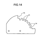
- FIG. 14 is a side view of the index plate for bolting to bracket of FIG. 6 ;
- FIG. 15 is a side perspective view of latch handle which is mounted to a proximal end of bracket of FIG. 6 ;
- FIG. 16 is a side perspective view of rubber sleeve
- FIG. 17 is a cross-sectional view of rubber sleeve indicated by arrows in FIG. 16 ;
- FIG. 18 is a side view of screw knob with threads indicated on stem
- FIG. 19 is a detailed view of latch bar.
- FIG. 20 is a side perspective view of the device of FIG. 1 with the range of adjustment indicated in phantom;
- Over-spray refers to spray painting where paint is sprayed beyond the target.
- the device of this invention securely holds the part during repair, preparation, painting and storage.
- the rod positioning lock and the stationary latch handle provide one-handed operation of this invention.
- the ability to hold automotive parts at an angle both convenient to the painter and in a position similar to the part's position in use is important to achieve an aesthetically pleasing painted surface. Additionally, being able to move a part after it has been painted and storing the painted part during drying allows the painter to prepare, repair and paint additional automotive parts in a more efficient manner than leaving the part to dry in the painting booth. Also, the device of this invention enables the user to consolidate limited floor space during the drying and storing of the part.
- FIG. 1 illustrates a large automotive panel paint rack 100 of heavy gauge steel construction with a durable powder coat finish.
- Large panel paint rack 100 has a wheel 28 mounted base, indicated generally at 26 , the wheels, 28 in actual use conditions Total Lock® wheels, although other wheels that can be locked could be used, the wheels mounted on a pair of base arms 82 in turn mounted to base frame 80 , FIGS. 3A & 3B .
- An upright post 30 is centered over the base frame 80 mounted by fastening means such as nuts, bolts and welds.
- the upright post 30 has adjustment means in the form of an adjustment knob 32 that permits the upright post 30 , shown in detail in FIG. 4 , to adjustably receive inside post 34 and fix inside post 34 in the desired position by adjustment knob 32 .
- Adjustment knob 32 is mounted on a screw that protrudes from an aperture in upright post 30 and by friction means holds the inside post 34 in a desired position.
- a platform 38 is indicated at FIG. 1 composed of multiple parts.
- a pair of tee frames, apertured tee frame 56 and tee frame 76 combine to form the platform 38 although a single tee frame could be used.
- the tee frames 56 , 76 are mounted together such that they may be adjusted longitudinally relative to each other.
- Tee frames 56 , 57 are slidably mounted to rack 100 by being received into trunnion 88 which has sleeves 84 , 86 mounted to inside post 34 .
- a second adjustment knob 32 ′ frictionally fixes tee frame 76 in place within trunnion sleeve 84 shown in detail in FIG. 6 .
- Apertured tee frame 56 is held in the desired position by means of pin 66 received by apertured tee frame 56 , in turn held in position in sleeve 86 .
- Each tee frame 56 , 76 has a pair of adjustable arm support members 42 of square tubular steel each having an adjustment hook 46 fixedly mounted thereto.
- Each arm support member 42 is received into a tubular member 54 , 68 of their respective tee frame 56 , 76 .
- Arm support members 42 are fixed in position by use screw threads 52 of screw knobs 50 ′, shown in detail at FIG. 18 .
- arm support members 42 are symmetrically placed such that the panel to be painted is balanced there between.
- Hook members 46 ′ and 46 ′′ are fixedly positioned on the outer end of each arm support member 42 such that the hooks are positioned at differing angles to compensate for the difference of tubular member 54 and 68 .
- hook member 46 ′ is positioned 20 degrees from vertical and hook member 46 ′′ is positioned 6 degrees from vertical although other angles could be utilized.
- Hook members 46 are adjusted laterally by screw knobs 50 ′.
- Optional arm extension 106 is received by the outside end of arm support 42 and fixed there by means of screw knob 50 .
- Arm extension 106 has an extra segment, again with hook members 46 ′′′, such that a more difficult to position panel, such as a tail gate, may be grasped and hung between the extension arm supports 106 .
- support arm 42 may be repositioned such that the hook member 46 attached thereto hangs in an out of the way position.
- Bracket 90 shown in detail in FIGS. 2 and 6 , is pivotably mounted to proximal end 36 of inside post 34 , FIG. 5 , by fastening means, such as bolt and nut, received by orifice 94 of central post 34 and aperture 92 of bracket 90 .
- Bracket 90 has a dual trunnion sleeve 88 support mounted thereon, FIG. 6 , a sleeve 84 for receiving a Tee frame 76 and a sleeve 86 for receiving an apertured Tee frame 56 .
- Bracket 90 is of U-shaped metal and receives rod positioning lock 60 , shown in detail at FIG. 13 , which fastens and releases bracket about index plate 70 , shown in detail at FIG. 14 , which is in turn pivotably mounted to inside post 34 .
- User can position the rack 100 in a table-like position, as shown in FIG. 1 , by manually releasing rod positioning lock 60 by pulling outwardly on rod 60 releasing a latch bar 72 , shown in detail in FIG. 19 and generally at FIG.
- index plate 70 has multiple slots 74 formed therein permitting the rack 100 to be positioned in a table-like position, with tee frame 76 and apertured tee frame 56 generally horizontal, as shown in FIG. 1 and rack 100 may be positioned in a generally upright position as shown in FIG. 20 .
- seven positions are accommodated by the index plate 70 provided although it is understood that more positions could be accommodated by forming more slots in index plate 70 .
- Both tee frame 76 shown in detail in FIG. 7
- apertured tee frame 56 FIG. 8
- tee frame 76 has fixedly mounted perpendicularly at the distal end 78 of tee frame 76 and distal end 58 of apertured tee frame 56 a pair of tubular members 68 and 54 , fixedly mounted to each other by welds or other fastening means, each to receive an arm support member 42 .
- Each arm support member 42 has fixedly mounted thereon a hook member 46 for attaching a part to be repaired, prepared or painted.
- the hook members 46 are mounted such that they compensate for this difference in mounting position of the arm support members 42 , namely the upper support member 42 has a hook member 46 ′′ FIG. 9 , mounted at a smaller angle than the hook member 46 ′ mounted on the lower support member 42 FIG. 10 , for the support arms 42 mounted on the apertured tee frame 56 .
- the support arms 42 mounted on the tee frame 76 have hooks 46 that point in an opposite direction from those hooks mounted on apertured tee frame 56 . This opposite tensioned positioning permits a secure temporary positioning of an automotive part on this rack 100 .
- the upper hook members 46 are attached to orifices provided in the inside portions of the automotive panels, the second, lower set of hook members 46 are then positioned and fixed by screw knobs 50 ′.
- Arm extensions 106 are optionally used when needed, e.g. when painting a tail gate, the are extensions 106 stored on the base 26 and held in both the place of storage and the place of use by screw knobs 50 .
- Latch handle 62 shown in detail at FIG. 15 , with spray shield 64 mounted by fastening means, such as screw, nuts and bolts or other fastening means, to a proximal end 98 of bracket, FIG. 1 & 2 .
- Rubber sleeves 110 shown in detail in FIGS. 16 & 17 , and indicated at FIG. 1 , are provided to shield the screw thread 52 formed on each screw knob 50 from paint over spray.
- Rack 100 may be adjusted laterally by releasing screw knobs 50 ′ mounted to arm supports 42 to allow arm supports to be spread apart while still received by tubular members 68 .
- Tubular members 68 receive the non-hook end of arm supports 42 and may be adjusted longitudinally to expand and retracted to a storage size, which illustrates platform tee frame 40 in a retracted position on upright post 30 , also in a retracted position.
- Tee frame 40 support members 42 received at a first end by sleeve 44 which also may be adjusted in length by adjustment screw 50 .
- a hook member 46 is positioned at a second end of support member 42 which also may have it's position adjusted by an adjustment screw 50 .
- FIG. 20 indicates the full range of motion available to a user to position the large panel paint rack 100 . Shown in phantom is an automobile hood in an upright position at FIG. 20 . This indicates the flexibility of the large panel paint rack 100 .
- FIG. 20 illustrates the large panel paint rack 100 in a variety of positions with a variety of automotive panels positioned for painting. To avoid having to mask parts not needing painting, rather than mask the part in place on the automobile, panels needing painting are removed from the automobile and painted. Because automotive panels have internal holes formed during manufacture, the large panel paint rack 100 uses these holes to attach to the automotive panels to the hook members 46 of the device of this invention. Large panel paint rack 100 can hold large automotive panels exactly where they are wanted with a quick adjustment.
- the automotive parts are fixedly positioned on the large panel paint rack 100 so no inadvertent touching of the freshly painted part occurs.
- the large automotive panel parts may be easily centered on the large panel paint rack 100 which also increases their stability when mounted on such a rack 100 .
- the user manually positions the rack 100 by locking at least one wheel 28 .
- the user then depresses rod positioning lock 60 by squeezing rod 60 like a pistol grip and bring rack 100 to an upright position.
- the support arms 42 of apertured tee frame 56 , the upper tee frame are loosened by screw knobs 50 ′ and spread apart laterally with one side being locked by use of screw knob 50 ′.
- the panel is the attached by fitting hook 46 into an orifice on the inside surface of the panel and the second hook member 46 is positioned and screw knob 50 tightened.
- the hook members 46 are mounted such that they compensate for this difference in mounting position of the arm support members 42 , namely the upper support member 42 has a hook member 46 ′′ FIG. 9 , mounted at a smaller angle than the hook member 46 ′ mounted on the lower support member 42 FIG. 10 , for the support arms 42 mounted on the apertured tee frame 56 .
- the support arms 42 mounted on the tee frame 76 have hooks 46 that point in an opposite direction from those hooks mounted on apertured tee frame 56 .
- Tee frame 56 is adjusted longitudinally relative to apertured tee frame 76 Adjustment knob 32 ′ is tightened and pin 66 is placed into an aperture of apertured tee frame 56 .
- the panel to be repaired, prepared or painted is firmly mounted on the rack 100 user may, using one hand, re-position the rack 100 by depressing rod position lock 60 to release the latch bar 72 from the index plate 70 , manually re-positioned and latched into place by releasing the rod positioning lock 60 such that the latch bar 72 is received by a slot 74 and holding rack 100 in the desired position.
- Large panel paint rack 100 can hold large automotive panels exactly where they are wanted with a quick adjustment.
- the panel parts can be positioned exactly as they would be found on the vehicle, with no masking required, with no missed edges and with better color and surface texture matches. After painting, the parts can be moved easily out of the way no matter how wet the paint is, freeing up the spray booth and making the spray booth and the worker more efficient.
Abstract
Description
Claims (19)
Priority Applications (1)
| Application Number | Priority Date | Filing Date | Title |
|---|---|---|---|
| US10/982,007 US7448606B1 (en) | 2003-12-04 | 2004-11-04 | Large automotive panel paint rack |
Applications Claiming Priority (2)
| Application Number | Priority Date | Filing Date | Title |
|---|---|---|---|
| US52677103P | 2003-12-04 | 2003-12-04 | |
| US10/982,007 US7448606B1 (en) | 2003-12-04 | 2004-11-04 | Large automotive panel paint rack |
Publications (1)
| Publication Number | Publication Date |
|---|---|
| US7448606B1 true US7448606B1 (en) | 2008-11-11 |
Family
ID=39940727
Family Applications (1)
| Application Number | Title | Priority Date | Filing Date |
|---|---|---|---|
| US10/982,007 Active 2025-04-11 US7448606B1 (en) | 2003-12-04 | 2004-11-04 | Large automotive panel paint rack |
Country Status (1)
| Country | Link |
|---|---|
| US (1) | US7448606B1 (en) |
Cited By (64)
| Publication number | Priority date | Publication date | Assignee | Title |
|---|---|---|---|---|
| US20070277360A1 (en) * | 2006-04-27 | 2007-12-06 | Pogorzelski Stanley Frank | Blade changer apparatus |
| US20080046120A1 (en) * | 2006-08-15 | 2008-02-21 | Jan Christian Mangelsen | Modular robotic workpiece holder and method for using same |
| US20090064907A1 (en) * | 2007-09-06 | 2009-03-12 | Richard Proehl | Adjustable Holding Apparatus |
| US20090102109A1 (en) * | 2004-12-03 | 2009-04-23 | Kuka Roboter Gmbh | Workpiece positioning device |
| US20090108148A1 (en) * | 2007-10-26 | 2009-04-30 | Johnson Bryan T | Adjustable stand |
| US20090184217A1 (en) * | 2008-01-23 | 2009-07-23 | Sprout James M | Stand system for holding parts, such as automobile parts, during painting |
| US20100126415A1 (en) * | 2007-04-16 | 2010-05-27 | Ulvac, Inc. | Conveyor and deposition apparatus, and maintenance method thereof |
| US20100133405A1 (en) * | 2008-12-03 | 2010-06-03 | Kia Motors Corporation | Holding unit for panel transmitting device |
| US7798479B1 (en) * | 2005-12-01 | 2010-09-21 | The United States Of America As Represented By The Secretary Of The Navy | Method and apparatus for horizontal assembly of a high-voltage feed-through bushing |
| US20110079947A1 (en) * | 2009-09-14 | 2011-04-07 | Masters Jack A | Model airplane work station |
| US20110101586A1 (en) * | 2009-11-02 | 2011-05-05 | Donald Scott Lands | Automobile rotisserie |
| US20110260026A1 (en) * | 2010-04-23 | 2011-10-27 | Hon Hai Precision Industry Co., Ltd. | Mounting bracket for display |
| US20110260384A1 (en) * | 2010-04-21 | 2011-10-27 | Earl Eugene Waters | Fixture and method for supporting door panels during painting and finishing |
| US20110316211A1 (en) * | 2010-06-25 | 2011-12-29 | Halladay Robert B | Work Table |
| US20120145977A1 (en) * | 2010-12-14 | 2012-06-14 | Kenneth A Hufstater | Chair Lifting and Moving Assembly |
| US20120163920A1 (en) * | 2010-12-23 | 2012-06-28 | Alain Desmeules | Support assembly for a drive mechanism for the installation of geothermal conduits adjacent a foundation wall inside or outside a building structure |
| US20120210835A1 (en) * | 2009-09-14 | 2012-08-23 | Combihout Beheer B.V. | Transfer car, and a method of machining a panel in a flat bed machine |
| US20120240849A1 (en) * | 2011-03-23 | 2012-09-27 | Deshler Donald T | Painting stand for vehicle body panels |
| US20120276298A1 (en) * | 2008-10-10 | 2012-11-01 | R-Coating, Inc. | Trunnion painting fixture |
| US8328173B1 (en) * | 2010-09-01 | 2012-12-11 | Desforge Steven L | Support stand system for automobile parts |
| US20130026691A1 (en) * | 2010-09-14 | 2013-01-31 | Honda Motor Co., Ltd. | Vertically-oriented fixture for selectably holding dissimilar workpieces |
| US8529181B1 (en) * | 2010-11-22 | 2013-09-10 | Telpro, Inc. | Wallboard support system |
| US20130299650A1 (en) * | 2012-05-11 | 2013-11-14 | Daniel L. Morris | Zero turn lawnmower mounting support arm |
| AU2013205835B1 (en) * | 2013-05-13 | 2013-11-14 | Ma, Xia Khanh MR | Advance panel stand ( a.p.s ) |
| US8690137B2 (en) | 2010-09-14 | 2014-04-08 | Honda Motor Co., Ltd. | Fixture for selectably holding dissimilar workpieces |
| US20140165376A1 (en) * | 2012-12-14 | 2014-06-19 | United Technologies Corporation | Cat arc process and part holding apparatus |
| US20140201963A1 (en) * | 2013-01-24 | 2014-07-24 | Minetec S.A. | Overturning equipment for hoppers |
| US8794614B2 (en) * | 2010-09-23 | 2014-08-05 | Lasse Friis | Expandable workbench and a method of use |
| US20140227073A1 (en) * | 2013-01-15 | 2014-08-14 | Babcock & Wilcox Power Generation Group, Inc. | Catalyst loading and unloading device and methods therefor |
| US20150026959A1 (en) * | 2013-07-23 | 2015-01-29 | Terin Dumas | Construction retention device |
| GB2517687A (en) * | 2013-08-27 | 2015-03-04 | Xia Khanh Ma | Advance Panel Stand |
| US20150098772A1 (en) * | 2013-10-07 | 2015-04-09 | Norman D. Nelson | Electric hydraulic catalyst loading and unloading device and methods therefor |
| US9016664B1 (en) | 2011-06-14 | 2015-04-28 | William J. Powers | Spin stand device |
| US20150167304A1 (en) * | 2012-07-06 | 2015-06-18 | Wobben Properties Gmbh | Foundation for wind turbine |
| US20150231780A1 (en) * | 2014-02-17 | 2015-08-20 | Hirobel LLC | Bicycle clamp |
| US20150325985A1 (en) * | 2014-05-08 | 2015-11-12 | Quanta Associates, Lp | Rotating Conductor Holder |
| US20160023229A1 (en) * | 2014-07-22 | 2016-01-28 | Innovative Tools & Technologies, Inc. | Stand for one or more vehicle parts |
| US20160025433A1 (en) * | 2014-07-24 | 2016-01-28 | Stoneage, Inc. | Flexible tube cleaning lance positioner frame apparatus |
| WO2016085327A3 (en) * | 2014-11-27 | 2016-08-04 | Materieeldienst Beverwijk B.V. | Apparatus and process for moving packages of finishing materials and transferring the packages to supports |
| NL1041070A (en) * | 2014-11-27 | 2016-08-17 | Van Lit Adrianus | Apparatus and method for moving and supporting transfer of finishing materials packages. |
| US20160243887A1 (en) * | 2015-02-20 | 2016-08-25 | Samuel Brewer | Taxidermist's fixture and method of using the same |
| US9427849B2 (en) * | 2014-11-01 | 2016-08-30 | Edward B McMillan | Adjustable workpiece repair and buildup stand |
| USD806454S1 (en) * | 2016-02-15 | 2018-01-02 | Patrick G Phillippi | Spray rack |
| US9909325B2 (en) * | 2014-11-06 | 2018-03-06 | Etablissements Pierre Grehal Et Cie Sa | Mechanism for fastening in a swivelling manner a plate carrier to a telescopic mast of a plate-lifting apparatus, and plate-lifting apparatus equipped with this mechanism |
| US20180229011A1 (en) * | 2017-02-15 | 2018-08-16 | Biosense Webster (Israel) Ltd. | Planetary gear assembly for sputtering multiple balloon catheter distal ends |
| US10113574B1 (en) * | 2015-09-24 | 2018-10-30 | Jeffrey A. Bileth | Workbench panel holder clamp fixture and system |
| US10322430B2 (en) | 2016-11-13 | 2019-06-18 | Harold Dean Miller | Flexible articulating painting stand for vehicle bumpers |
| US20190321925A1 (en) * | 2018-04-19 | 2019-10-24 | Amazon Technologies, Inc. | Base pod assembly fixture and method |
| US10537097B2 (en) | 2010-02-16 | 2020-01-21 | Viacell, Llc | Methods for treating red blood cells |
| JP2020011752A (en) * | 2018-07-18 | 2020-01-23 | トヨタ自動車九州株式会社 | Bumper conveyance device |
| US20200066183A1 (en) * | 2018-08-25 | 2020-02-27 | Jeremy langton | Apparatus for practicing removal of a deformative damage to a workpiece |
| US10611612B2 (en) * | 2017-09-29 | 2020-04-07 | Haiyan Aihua Machinery Co., LTD | Lifter |
| US10684082B2 (en) | 2014-07-24 | 2020-06-16 | Stoneage, Inc. | Flexible tube cleaning lance positioner frame apparatus |
| US10828215B2 (en) * | 2015-10-23 | 2020-11-10 | Universite De Caen | System and handling method to facilitate the maintenance of a bed unit, in particular a healthcare bed |
| US10953503B2 (en) * | 2018-10-05 | 2021-03-23 | Compagnie Plastic Omnium | Vehicle body part rack with lateral supports able to rotate the vehicle body part |
| US11167219B2 (en) * | 2017-01-19 | 2021-11-09 | Traxxas Lp | Multi-position body mount for model vehicle |
| US20220058302A1 (en) * | 2020-08-19 | 2022-02-24 | Adrian Ramirez | Personalized Vehicle Component System |
| US11312601B1 (en) * | 2021-11-22 | 2022-04-26 | Shenzhen Global Purchase Trading Co., Ltd | Movable lifting bracket |
| US11465702B2 (en) * | 2019-03-27 | 2022-10-11 | Marty Williams | Storage stand |
| US11518004B2 (en) * | 2019-10-11 | 2022-12-06 | Innovative Tools & Technologies, Inc. | Bumper apparatus |
| USD974692S1 (en) | 2020-08-10 | 2023-01-03 | John D. Cullinan | Vehicle hardtop lift |
| US11713932B2 (en) | 2020-08-18 | 2023-08-01 | Stoneage, Inc. | Flexible tube cleaning lance positioner frame apparatus |
| US11813637B1 (en) * | 2022-04-20 | 2023-11-14 | David Petras | Painting support assembly |
| KR102631790B1 (en) * | 2023-08-14 | 2024-01-31 | 권익형 | Paint supporting structuer for car |
Citations (17)
| Publication number | Priority date | Publication date | Assignee | Title |
|---|---|---|---|---|
| US569289A (en) | 1896-10-13 | Support for bicycles | ||
| US653519A (en) | 1899-08-04 | 1900-07-10 | Marshall Albert Masters | Bicycle-repair jack. |
| US2803872A (en) | 1955-01-14 | 1957-08-27 | George J Massa | Rack for holding automobile body parts |
| US2827690A (en) | 1954-11-01 | 1958-03-25 | Florence N Williams | Holder for vehicle body panels |
| US3643935A (en) * | 1969-10-02 | 1972-02-22 | Archie Y Bell | Door-hanging workbench |
| US3858864A (en) | 1973-03-07 | 1975-01-07 | Raymond Lee Organization Inc | Vehicle door supporting apparatus |
| US4245786A (en) | 1979-04-16 | 1981-01-20 | Abrahamsen Johan E | Oscillating lawn spray with variable width and length |
| USD303031S (en) | 1987-01-28 | 1989-08-22 | Ellis Mark L | Automobile hardtop storage cart/rack |
| US4880194A (en) | 1987-07-21 | 1989-11-14 | John Geise | Apparatus and method for supporting articles |
| US5141211A (en) * | 1991-08-15 | 1992-08-25 | Adams Jr Joseph E | Universal work station |
| US5675417A (en) | 1994-05-23 | 1997-10-07 | It's Dents Or Us, Inc. | Infinitely adjustable automobile body repair light panel support |
| US5707450A (en) * | 1996-05-07 | 1998-01-13 | Thompson; Brad R. | Apparatus for holding a vehicle body part |
| US5709373A (en) | 1995-12-04 | 1998-01-20 | Wasylynko; David E. | Portable ski and snowboard tuning table |
| US6003830A (en) * | 1998-05-06 | 1999-12-21 | Egan; Roger | Portable engine stand for motorcycle engines |
| US6024348A (en) * | 1998-10-28 | 2000-02-15 | It's Dents Or Us, Inc. | Adjustable clamping stand for supporting automobile panels |
| US6173947B1 (en) | 1996-04-01 | 2001-01-16 | Innovative Tools & Technologies, Inc. | Automotive bumper stand |
| US6409128B1 (en) * | 1999-09-03 | 2002-06-25 | Donald T. Deshler | Painting stand for vehicle parts such as bumpers |
-
2004
- 2004-11-04 US US10/982,007 patent/US7448606B1/en active Active
Patent Citations (17)
| Publication number | Priority date | Publication date | Assignee | Title |
|---|---|---|---|---|
| US569289A (en) | 1896-10-13 | Support for bicycles | ||
| US653519A (en) | 1899-08-04 | 1900-07-10 | Marshall Albert Masters | Bicycle-repair jack. |
| US2827690A (en) | 1954-11-01 | 1958-03-25 | Florence N Williams | Holder for vehicle body panels |
| US2803872A (en) | 1955-01-14 | 1957-08-27 | George J Massa | Rack for holding automobile body parts |
| US3643935A (en) * | 1969-10-02 | 1972-02-22 | Archie Y Bell | Door-hanging workbench |
| US3858864A (en) | 1973-03-07 | 1975-01-07 | Raymond Lee Organization Inc | Vehicle door supporting apparatus |
| US4245786A (en) | 1979-04-16 | 1981-01-20 | Abrahamsen Johan E | Oscillating lawn spray with variable width and length |
| USD303031S (en) | 1987-01-28 | 1989-08-22 | Ellis Mark L | Automobile hardtop storage cart/rack |
| US4880194A (en) | 1987-07-21 | 1989-11-14 | John Geise | Apparatus and method for supporting articles |
| US5141211A (en) * | 1991-08-15 | 1992-08-25 | Adams Jr Joseph E | Universal work station |
| US5675417A (en) | 1994-05-23 | 1997-10-07 | It's Dents Or Us, Inc. | Infinitely adjustable automobile body repair light panel support |
| US5709373A (en) | 1995-12-04 | 1998-01-20 | Wasylynko; David E. | Portable ski and snowboard tuning table |
| US6173947B1 (en) | 1996-04-01 | 2001-01-16 | Innovative Tools & Technologies, Inc. | Automotive bumper stand |
| US5707450A (en) * | 1996-05-07 | 1998-01-13 | Thompson; Brad R. | Apparatus for holding a vehicle body part |
| US6003830A (en) * | 1998-05-06 | 1999-12-21 | Egan; Roger | Portable engine stand for motorcycle engines |
| US6024348A (en) * | 1998-10-28 | 2000-02-15 | It's Dents Or Us, Inc. | Adjustable clamping stand for supporting automobile panels |
| US6409128B1 (en) * | 1999-09-03 | 2002-06-25 | Donald T. Deshler | Painting stand for vehicle parts such as bumpers |
Non-Patent Citations (3)
| Title |
|---|
| Collison Services, Makes Handling Parts a Breeze the Roto Maxx Aug. 20, 2001. |
| The Ultimate Auto Body Parts Stand, Kno: Greef MFG. Feb. 2002, Canada. |
| Tools & Equipment Flex Bench, undated, p. 45 Catalog. Collision Services Nov. 4, 2004. |
Cited By (96)
| Publication number | Priority date | Publication date | Assignee | Title |
|---|---|---|---|---|
| US20090102109A1 (en) * | 2004-12-03 | 2009-04-23 | Kuka Roboter Gmbh | Workpiece positioning device |
| US8118291B2 (en) * | 2004-12-03 | 2012-02-21 | Kuka Roboter Gmbh | Workpiece positioning device |
| US7798479B1 (en) * | 2005-12-01 | 2010-09-21 | The United States Of America As Represented By The Secretary Of The Navy | Method and apparatus for horizontal assembly of a high-voltage feed-through bushing |
| US8382082B2 (en) * | 2005-12-01 | 2013-02-26 | The United States Of America As Represented By Secretary Of The Navy | Method and apparatus for horizontal assembly of a high-voltage feed-through bushing |
| US20100281675A1 (en) * | 2005-12-01 | 2010-11-11 | Daniel Gath Meeks | Method and apparatus for horizontal assembly of a high-voltage feed-through bushing |
| US20070277360A1 (en) * | 2006-04-27 | 2007-12-06 | Pogorzelski Stanley Frank | Blade changer apparatus |
| US8146901B2 (en) * | 2006-08-15 | 2012-04-03 | Genesis Systems Group, Llc | Modular robotic workpiece holder and method for using same |
| US20080046120A1 (en) * | 2006-08-15 | 2008-02-21 | Jan Christian Mangelsen | Modular robotic workpiece holder and method for using same |
| US20100126415A1 (en) * | 2007-04-16 | 2010-05-27 | Ulvac, Inc. | Conveyor and deposition apparatus, and maintenance method thereof |
| US8740205B2 (en) * | 2007-04-16 | 2014-06-03 | Ulvac, Inc. | Conveyor and deposition apparatus, and maintenance method thereof |
| US7950635B2 (en) * | 2007-09-06 | 2011-05-31 | Richard Proehl | Adjustable holding apparatus |
| US20090064907A1 (en) * | 2007-09-06 | 2009-03-12 | Richard Proehl | Adjustable Holding Apparatus |
| US7988137B2 (en) * | 2007-10-26 | 2011-08-02 | Innovative Tools & Technologies, Inc. | Adjustable stand |
| US20090108148A1 (en) * | 2007-10-26 | 2009-04-30 | Johnson Bryan T | Adjustable stand |
| US20090184217A1 (en) * | 2008-01-23 | 2009-07-23 | Sprout James M | Stand system for holding parts, such as automobile parts, during painting |
| US20120276298A1 (en) * | 2008-10-10 | 2012-11-01 | R-Coating, Inc. | Trunnion painting fixture |
| US8453308B2 (en) * | 2008-10-10 | 2013-06-04 | R-Coating, Inc. | Trunnion painting fixture |
| US8172210B2 (en) * | 2008-12-03 | 2012-05-08 | Kia Motors Corporation | Holding unit for panel transmitting device |
| US20100133405A1 (en) * | 2008-12-03 | 2010-06-03 | Kia Motors Corporation | Holding unit for panel transmitting device |
| US20120210835A1 (en) * | 2009-09-14 | 2012-08-23 | Combihout Beheer B.V. | Transfer car, and a method of machining a panel in a flat bed machine |
| US8430388B2 (en) * | 2009-09-14 | 2013-04-30 | Jack A. Masters | Model airplane work station |
| US20110079947A1 (en) * | 2009-09-14 | 2011-04-07 | Masters Jack A | Model airplane work station |
| US8596627B2 (en) * | 2009-11-02 | 2013-12-03 | Wurk Metal Products, Inc. | Automobile rotisserie |
| US20110101586A1 (en) * | 2009-11-02 | 2011-05-05 | Donald Scott Lands | Automobile rotisserie |
| US10537097B2 (en) | 2010-02-16 | 2020-01-21 | Viacell, Llc | Methods for treating red blood cells |
| US8177207B2 (en) * | 2010-04-21 | 2012-05-15 | Earl Eugene Waters | Fixture and method for supporting door panels during painting and finishing |
| US20110260384A1 (en) * | 2010-04-21 | 2011-10-27 | Earl Eugene Waters | Fixture and method for supporting door panels during painting and finishing |
| US20110260026A1 (en) * | 2010-04-23 | 2011-10-27 | Hon Hai Precision Industry Co., Ltd. | Mounting bracket for display |
| US8276864B2 (en) * | 2010-04-23 | 2012-10-02 | Hong Fu Jin Precision Industry (Shenzhen) Co., Ltd. | Mounting bracket for display |
| US8366084B2 (en) * | 2010-06-25 | 2013-02-05 | Halladay Robert B | Work table |
| US20110316211A1 (en) * | 2010-06-25 | 2011-12-29 | Halladay Robert B | Work Table |
| US8328173B1 (en) * | 2010-09-01 | 2012-12-11 | Desforge Steven L | Support stand system for automobile parts |
| US20130026691A1 (en) * | 2010-09-14 | 2013-01-31 | Honda Motor Co., Ltd. | Vertically-oriented fixture for selectably holding dissimilar workpieces |
| US9469016B2 (en) * | 2010-09-14 | 2016-10-18 | Honda Motor Co., Ltd. | Vertically-oriented fixture for selectably holding dissimilar workpieces |
| US9527204B2 (en) | 2010-09-14 | 2016-12-27 | Honda Motor Co., Ltd. | Fixture for selectably holding dissimilar workpieces |
| US8690137B2 (en) | 2010-09-14 | 2014-04-08 | Honda Motor Co., Ltd. | Fixture for selectably holding dissimilar workpieces |
| US8794614B2 (en) * | 2010-09-23 | 2014-08-05 | Lasse Friis | Expandable workbench and a method of use |
| US8529181B1 (en) * | 2010-11-22 | 2013-09-10 | Telpro, Inc. | Wallboard support system |
| US20120145977A1 (en) * | 2010-12-14 | 2012-06-14 | Kenneth A Hufstater | Chair Lifting and Moving Assembly |
| US20120163920A1 (en) * | 2010-12-23 | 2012-06-28 | Alain Desmeules | Support assembly for a drive mechanism for the installation of geothermal conduits adjacent a foundation wall inside or outside a building structure |
| US20120240849A1 (en) * | 2011-03-23 | 2012-09-27 | Deshler Donald T | Painting stand for vehicle body panels |
| US9358564B2 (en) * | 2011-03-23 | 2016-06-07 | Donald T. Deshler | Painting stand for vehicle body panels |
| US9016664B1 (en) | 2011-06-14 | 2015-04-28 | William J. Powers | Spin stand device |
| US8733841B2 (en) * | 2012-05-11 | 2014-05-27 | Daniel L. Morris | Zero turn lawnmower mounting support arm |
| US20130299650A1 (en) * | 2012-05-11 | 2013-11-14 | Daniel L. Morris | Zero turn lawnmower mounting support arm |
| US20150167304A1 (en) * | 2012-07-06 | 2015-06-18 | Wobben Properties Gmbh | Foundation for wind turbine |
| US9976307B2 (en) * | 2012-07-06 | 2018-05-22 | Wobben Properties Gmbh | Foundation for wind turbine |
| US9102023B2 (en) * | 2012-12-14 | 2015-08-11 | United Technologies Corporation | CAT ARC process and part holding apparatus |
| US20140165376A1 (en) * | 2012-12-14 | 2014-06-19 | United Technologies Corporation | Cat arc process and part holding apparatus |
| US20140227073A1 (en) * | 2013-01-15 | 2014-08-14 | Babcock & Wilcox Power Generation Group, Inc. | Catalyst loading and unloading device and methods therefor |
| US9457826B2 (en) * | 2013-01-15 | 2016-10-04 | The Babcock & Wilcox Company | Catalyst loading and unloading device and methods therefor |
| US9527709B2 (en) * | 2013-01-24 | 2016-12-27 | Minetec S.A. | Overturning equipment for hoppers |
| US20140201963A1 (en) * | 2013-01-24 | 2014-07-24 | Minetec S.A. | Overturning equipment for hoppers |
| AU2013205835B1 (en) * | 2013-05-13 | 2013-11-14 | Ma, Xia Khanh MR | Advance panel stand ( a.p.s ) |
| US20150026959A1 (en) * | 2013-07-23 | 2015-01-29 | Terin Dumas | Construction retention device |
| GB2517687A (en) * | 2013-08-27 | 2015-03-04 | Xia Khanh Ma | Advance Panel Stand |
| GB2517687B (en) * | 2013-08-27 | 2015-07-29 | Xia Khanh Ma | Stand for articles to be painted |
| US9896308B2 (en) * | 2013-10-07 | 2018-02-20 | The Babcock & Wilcox Company | Electric hydraulic catalyst loading and unloading device and methods therefor |
| CN104645826A (en) * | 2013-10-07 | 2015-05-27 | 巴布科克和威尔科克斯能量产生集团公司 | Electric hydraulic catalyst loading and unloading device and methods therefor |
| US20150098772A1 (en) * | 2013-10-07 | 2015-04-09 | Norman D. Nelson | Electric hydraulic catalyst loading and unloading device and methods therefor |
| US10160112B2 (en) * | 2014-02-17 | 2018-12-25 | Hirobel LLC | Bicycle clamp |
| US20150231780A1 (en) * | 2014-02-17 | 2015-08-20 | Hirobel LLC | Bicycle clamp |
| US10177545B2 (en) * | 2014-05-08 | 2019-01-08 | Quanta Associates, L.P. | Rotating conductor holder |
| US20150325985A1 (en) * | 2014-05-08 | 2015-11-12 | Quanta Associates, Lp | Rotating Conductor Holder |
| US20160023229A1 (en) * | 2014-07-22 | 2016-01-28 | Innovative Tools & Technologies, Inc. | Stand for one or more vehicle parts |
| US10744526B2 (en) * | 2014-07-22 | 2020-08-18 | Innovative Tools & Technologies, Inc. | Stand for one or more vehicle parts |
| US10024613B2 (en) * | 2014-07-24 | 2018-07-17 | Stoneage, Inc. | Flexible tube cleaning lance positioner frame apparatus |
| US20160025433A1 (en) * | 2014-07-24 | 2016-01-28 | Stoneage, Inc. | Flexible tube cleaning lance positioner frame apparatus |
| US10684082B2 (en) | 2014-07-24 | 2020-06-16 | Stoneage, Inc. | Flexible tube cleaning lance positioner frame apparatus |
| US9427849B2 (en) * | 2014-11-01 | 2016-08-30 | Edward B McMillan | Adjustable workpiece repair and buildup stand |
| US9909325B2 (en) * | 2014-11-06 | 2018-03-06 | Etablissements Pierre Grehal Et Cie Sa | Mechanism for fastening in a swivelling manner a plate carrier to a telescopic mast of a plate-lifting apparatus, and plate-lifting apparatus equipped with this mechanism |
| NL1041070A (en) * | 2014-11-27 | 2016-08-17 | Van Lit Adrianus | Apparatus and method for moving and supporting transfer of finishing materials packages. |
| WO2016085327A3 (en) * | 2014-11-27 | 2016-08-04 | Materieeldienst Beverwijk B.V. | Apparatus and process for moving packages of finishing materials and transferring the packages to supports |
| US20160243887A1 (en) * | 2015-02-20 | 2016-08-25 | Samuel Brewer | Taxidermist's fixture and method of using the same |
| US10113574B1 (en) * | 2015-09-24 | 2018-10-30 | Jeffrey A. Bileth | Workbench panel holder clamp fixture and system |
| US10828215B2 (en) * | 2015-10-23 | 2020-11-10 | Universite De Caen | System and handling method to facilitate the maintenance of a bed unit, in particular a healthcare bed |
| USD806454S1 (en) * | 2016-02-15 | 2018-01-02 | Patrick G Phillippi | Spray rack |
| US10322430B2 (en) | 2016-11-13 | 2019-06-18 | Harold Dean Miller | Flexible articulating painting stand for vehicle bumpers |
| US11167219B2 (en) * | 2017-01-19 | 2021-11-09 | Traxxas Lp | Multi-position body mount for model vehicle |
| US10758716B2 (en) * | 2017-02-15 | 2020-09-01 | Biosense Webster (Israel) Ltd. | Planetary gear assembly for sputtering multiple balloon catheter distal ends |
| US20180229011A1 (en) * | 2017-02-15 | 2018-08-16 | Biosense Webster (Israel) Ltd. | Planetary gear assembly for sputtering multiple balloon catheter distal ends |
| US10611612B2 (en) * | 2017-09-29 | 2020-04-07 | Haiyan Aihua Machinery Co., LTD | Lifter |
| US11065728B2 (en) * | 2018-04-19 | 2021-07-20 | Amazon Technologies, Inc. | Base pod assembly fixture and method |
| US20190321925A1 (en) * | 2018-04-19 | 2019-10-24 | Amazon Technologies, Inc. | Base pod assembly fixture and method |
| DE112019002031B4 (en) | 2018-04-19 | 2024-03-14 | Amazon Technologies, Inc. | Basic POD mounting device and method |
| JP2020011752A (en) * | 2018-07-18 | 2020-01-23 | トヨタ自動車九州株式会社 | Bumper conveyance device |
| US20200066183A1 (en) * | 2018-08-25 | 2020-02-27 | Jeremy langton | Apparatus for practicing removal of a deformative damage to a workpiece |
| US10953503B2 (en) * | 2018-10-05 | 2021-03-23 | Compagnie Plastic Omnium | Vehicle body part rack with lateral supports able to rotate the vehicle body part |
| US11465702B2 (en) * | 2019-03-27 | 2022-10-11 | Marty Williams | Storage stand |
| US11518004B2 (en) * | 2019-10-11 | 2022-12-06 | Innovative Tools & Technologies, Inc. | Bumper apparatus |
| USD974692S1 (en) | 2020-08-10 | 2023-01-03 | John D. Cullinan | Vehicle hardtop lift |
| US11713932B2 (en) | 2020-08-18 | 2023-08-01 | Stoneage, Inc. | Flexible tube cleaning lance positioner frame apparatus |
| US20220058302A1 (en) * | 2020-08-19 | 2022-02-24 | Adrian Ramirez | Personalized Vehicle Component System |
| US11312601B1 (en) * | 2021-11-22 | 2022-04-26 | Shenzhen Global Purchase Trading Co., Ltd | Movable lifting bracket |
| US11813637B1 (en) * | 2022-04-20 | 2023-11-14 | David Petras | Painting support assembly |
| KR102631790B1 (en) * | 2023-08-14 | 2024-01-31 | 권익형 | Paint supporting structuer for car |
Similar Documents
| Publication | Publication Date | Title |
|---|---|---|
| US7448606B1 (en) | Large automotive panel paint rack | |
| US6409128B1 (en) | Painting stand for vehicle parts such as bumpers | |
| US20080142652A1 (en) | Mobile paint rack | |
| US6158701A (en) | Painting stand for vehicle parts | |
| US8328173B1 (en) | Support stand system for automobile parts | |
| US8707976B2 (en) | Portable painting apparatus | |
| US6837934B1 (en) | Racking system | |
| US7753169B1 (en) | Wheeled support platform for a stepladder | |
| US5707450A (en) | Apparatus for holding a vehicle body part | |
| US10322430B2 (en) | Flexible articulating painting stand for vehicle bumpers | |
| US20090184217A1 (en) | Stand system for holding parts, such as automobile parts, during painting | |
| US8905391B2 (en) | Firearm holding device | |
| US5120013A (en) | Ladder shelf | |
| US7484594B1 (en) | Device for transporting long objects such as a ladder | |
| US7798095B2 (en) | Device to hold door for painting | |
| US6942735B2 (en) | Adjustable spray apparatus with multiple outlets | |
| US20020117524A1 (en) | Trunk mountable equipment rack | |
| US10744526B2 (en) | Stand for one or more vehicle parts | |
| US5894945A (en) | Multiple door paint rack system | |
| US7481323B2 (en) | Multi purpose door rack | |
| US20210146842A1 (en) | Vehicle mounted accessory | |
| US6457686B1 (en) | Handheld dryer support device | |
| US20080061201A1 (en) | Paint can and paintbrush holder attachment for ladders | |
| US20020134864A1 (en) | Extension holder for spray, caulk and paint devices | |
| US5797504A (en) | Portable hoisting system |
Legal Events
| Date | Code | Title | Description |
|---|---|---|---|
| AS | Assignment |
Owner name: INNOVATIVE TOOLS & TECHNOLOGIES, INC., MINNESOTA Free format text: ASSIGNMENT OF ASSIGNORS INTEREST;ASSIGNOR:JOHNSON, BRYAN THOMAS;REEL/FRAME:018884/0030 Effective date: 20070206 |
|
| STCF | Information on status: patent grant |
Free format text: PATENTED CASE |
|
| FPAY | Fee payment |
Year of fee payment: 4 |
|
| FPAY | Fee payment |
Year of fee payment: 8 |
|
| MAFP | Maintenance fee payment |
Free format text: PAYMENT OF MAINTENANCE FEE, 12TH YR, SMALL ENTITY (ORIGINAL EVENT CODE: M2553); ENTITY STATUS OF PATENT OWNER: SMALL ENTITY Year of fee payment: 12 |