US7450813B2 - Rare earth doped and large effective area optical fibers for fiber lasers and amplifiers - Google Patents
Rare earth doped and large effective area optical fibers for fiber lasers and amplifiers Download PDFInfo
- Publication number
- US7450813B2 US7450813B2 US11/693,633 US69363307A US7450813B2 US 7450813 B2 US7450813 B2 US 7450813B2 US 69363307 A US69363307 A US 69363307A US 7450813 B2 US7450813 B2 US 7450813B2
- Authority
- US
- United States
- Prior art keywords
- core
- fiber
- refractive index
- doped
- silica
- Prior art date
- Legal status (The legal status is an assumption and is not a legal conclusion. Google has not performed a legal analysis and makes no representation as to the accuracy of the status listed.)
- Expired - Fee Related
Links
Images


Classifications
-
- G—PHYSICS
- G02—OPTICS
- G02B—OPTICAL ELEMENTS, SYSTEMS OR APPARATUS
- G02B6/00—Light guides; Structural details of arrangements comprising light guides and other optical elements, e.g. couplings
- G02B6/02—Optical fibres with cladding with or without a coating
- G02B6/036—Optical fibres with cladding with or without a coating core or cladding comprising multiple layers
- G02B6/03616—Optical fibres characterised both by the number of different refractive index layers around the central core segment, i.e. around the innermost high index core layer, and their relative refractive index difference
-
- C—CHEMISTRY; METALLURGY
- C03—GLASS; MINERAL OR SLAG WOOL
- C03B—MANUFACTURE, SHAPING, OR SUPPLEMENTARY PROCESSES
- C03B37/00—Manufacture or treatment of flakes, fibres, or filaments from softened glass, minerals, or slags
- C03B37/01—Manufacture of glass fibres or filaments
- C03B37/012—Manufacture of preforms for drawing fibres or filaments
- C03B37/01205—Manufacture of preforms for drawing fibres or filaments starting from tubes, rods, fibres or filaments
- C03B37/01211—Manufacture of preforms for drawing fibres or filaments starting from tubes, rods, fibres or filaments by inserting one or more rods or tubes into a tube
- C03B37/01217—Manufacture of preforms for drawing fibres or filaments starting from tubes, rods, fibres or filaments by inserting one or more rods or tubes into a tube for making preforms of polarisation-maintaining optical fibres
-
- C—CHEMISTRY; METALLURGY
- C03—GLASS; MINERAL OR SLAG WOOL
- C03B—MANUFACTURE, SHAPING, OR SUPPLEMENTARY PROCESSES
- C03B37/00—Manufacture or treatment of flakes, fibres, or filaments from softened glass, minerals, or slags
- C03B37/01—Manufacture of glass fibres or filaments
- C03B37/012—Manufacture of preforms for drawing fibres or filaments
- C03B37/01205—Manufacture of preforms for drawing fibres or filaments starting from tubes, rods, fibres or filaments
- C03B37/01211—Manufacture of preforms for drawing fibres or filaments starting from tubes, rods, fibres or filaments by inserting one or more rods or tubes into a tube
- C03B37/0122—Manufacture of preforms for drawing fibres or filaments starting from tubes, rods, fibres or filaments by inserting one or more rods or tubes into a tube for making preforms of photonic crystal, microstructured or holey optical fibres
-
- C—CHEMISTRY; METALLURGY
- C03—GLASS; MINERAL OR SLAG WOOL
- C03B—MANUFACTURE, SHAPING, OR SUPPLEMENTARY PROCESSES
- C03B37/00—Manufacture or treatment of flakes, fibres, or filaments from softened glass, minerals, or slags
- C03B37/01—Manufacture of glass fibres or filaments
- C03B37/012—Manufacture of preforms for drawing fibres or filaments
- C03B37/014—Manufacture of preforms for drawing fibres or filaments made entirely or partially by chemical means, e.g. vapour phase deposition of bulk porous glass either by outside vapour deposition [OVD], or by outside vapour phase oxidation [OVPO] or by vapour axial deposition [VAD]
- C03B37/018—Manufacture of preforms for drawing fibres or filaments made entirely or partially by chemical means, e.g. vapour phase deposition of bulk porous glass either by outside vapour deposition [OVD], or by outside vapour phase oxidation [OVPO] or by vapour axial deposition [VAD] by glass deposition on a glass substrate, e.g. by inside-, modified-, plasma-, or plasma modified- chemical vapour deposition [ICVD, MCVD, PCVD, PMCVD], i.e. by thin layer coating on the inside or outside of a glass tube or on a glass rod
- C03B37/01807—Reactant delivery systems, e.g. reactant deposition burners
- C03B37/01838—Reactant delivery systems, e.g. reactant deposition burners for delivering and depositing additional reactants as liquids or solutions, e.g. for solution doping of the deposited glass
-
- C—CHEMISTRY; METALLURGY
- C03—GLASS; MINERAL OR SLAG WOOL
- C03C—CHEMICAL COMPOSITION OF GLASSES, GLAZES OR VITREOUS ENAMELS; SURFACE TREATMENT OF GLASS; SURFACE TREATMENT OF FIBRES OR FILAMENTS MADE FROM GLASS, MINERALS OR SLAGS; JOINING GLASS TO GLASS OR OTHER MATERIALS
- C03C13/00—Fibre or filament compositions
- C03C13/04—Fibre optics, e.g. core and clad fibre compositions
- C03C13/045—Silica-containing oxide glass compositions
- C03C13/046—Multicomponent glass compositions
-
- C—CHEMISTRY; METALLURGY
- C03—GLASS; MINERAL OR SLAG WOOL
- C03C—CHEMICAL COMPOSITION OF GLASSES, GLAZES OR VITREOUS ENAMELS; SURFACE TREATMENT OF GLASS; SURFACE TREATMENT OF FIBRES OR FILAMENTS MADE FROM GLASS, MINERALS OR SLAGS; JOINING GLASS TO GLASS OR OTHER MATERIALS
- C03C3/00—Glass compositions
- C03C3/04—Glass compositions containing silica
- C03C3/06—Glass compositions containing silica with more than 90% silica by weight, e.g. quartz
-
- C—CHEMISTRY; METALLURGY
- C03—GLASS; MINERAL OR SLAG WOOL
- C03C—CHEMICAL COMPOSITION OF GLASSES, GLAZES OR VITREOUS ENAMELS; SURFACE TREATMENT OF GLASS; SURFACE TREATMENT OF FIBRES OR FILAMENTS MADE FROM GLASS, MINERALS OR SLAGS; JOINING GLASS TO GLASS OR OTHER MATERIALS
- C03C3/00—Glass compositions
- C03C3/04—Glass compositions containing silica
- C03C3/076—Glass compositions containing silica with 40% to 90% silica, by weight
- C03C3/097—Glass compositions containing silica with 40% to 90% silica, by weight containing phosphorus, niobium or tantalum
-
- C—CHEMISTRY; METALLURGY
- C03—GLASS; MINERAL OR SLAG WOOL
- C03C—CHEMICAL COMPOSITION OF GLASSES, GLAZES OR VITREOUS ENAMELS; SURFACE TREATMENT OF GLASS; SURFACE TREATMENT OF FIBRES OR FILAMENTS MADE FROM GLASS, MINERALS OR SLAGS; JOINING GLASS TO GLASS OR OTHER MATERIALS
- C03C4/00—Compositions for glass with special properties
- C03C4/0071—Compositions for glass with special properties for laserable glass
-
- G—PHYSICS
- G02—OPTICS
- G02B—OPTICAL ELEMENTS, SYSTEMS OR APPARATUS
- G02B6/00—Light guides; Structural details of arrangements comprising light guides and other optical elements, e.g. couplings
- G02B6/02—Optical fibres with cladding with or without a coating
- G02B6/032—Optical fibres with cladding with or without a coating with non solid core or cladding
-
- G—PHYSICS
- G02—OPTICS
- G02B—OPTICAL ELEMENTS, SYSTEMS OR APPARATUS
- G02B6/00—Light guides; Structural details of arrangements comprising light guides and other optical elements, e.g. couplings
- G02B6/02—Optical fibres with cladding with or without a coating
- G02B6/036—Optical fibres with cladding with or without a coating core or cladding comprising multiple layers
- G02B6/03616—Optical fibres characterised both by the number of different refractive index layers around the central core segment, i.e. around the innermost high index core layer, and their relative refractive index difference
- G02B6/03622—Optical fibres characterised both by the number of different refractive index layers around the central core segment, i.e. around the innermost high index core layer, and their relative refractive index difference having 2 layers only
- G02B6/03633—Optical fibres characterised both by the number of different refractive index layers around the central core segment, i.e. around the innermost high index core layer, and their relative refractive index difference having 2 layers only arranged - -
-
- G—PHYSICS
- G02—OPTICS
- G02B—OPTICAL ELEMENTS, SYSTEMS OR APPARATUS
- G02B6/00—Light guides; Structural details of arrangements comprising light guides and other optical elements, e.g. couplings
- G02B6/02—Optical fibres with cladding with or without a coating
- G02B6/036—Optical fibres with cladding with or without a coating core or cladding comprising multiple layers
- G02B6/03616—Optical fibres characterised both by the number of different refractive index layers around the central core segment, i.e. around the innermost high index core layer, and their relative refractive index difference
- G02B6/03638—Optical fibres characterised both by the number of different refractive index layers around the central core segment, i.e. around the innermost high index core layer, and their relative refractive index difference having 3 layers only
-
- H—ELECTRICITY
- H01—ELECTRIC ELEMENTS
- H01S—DEVICES USING THE PROCESS OF LIGHT AMPLIFICATION BY STIMULATED EMISSION OF RADIATION [LASER] TO AMPLIFY OR GENERATE LIGHT; DEVICES USING STIMULATED EMISSION OF ELECTROMAGNETIC RADIATION IN WAVE RANGES OTHER THAN OPTICAL
- H01S3/00—Lasers, i.e. devices using stimulated emission of electromagnetic radiation in the infrared, visible or ultraviolet wave range
- H01S3/05—Construction or shape of optical resonators; Accommodation of active medium therein; Shape of active medium
- H01S3/06—Construction or shape of active medium
- H01S3/063—Waveguide lasers, i.e. whereby the dimensions of the waveguide are of the order of the light wavelength
- H01S3/067—Fibre lasers
- H01S3/06754—Fibre amplifiers
-
- C—CHEMISTRY; METALLURGY
- C03—GLASS; MINERAL OR SLAG WOOL
- C03B—MANUFACTURE, SHAPING, OR SUPPLEMENTARY PROCESSES
- C03B2201/00—Type of glass produced
- C03B2201/06—Doped silica-based glasses
- C03B2201/08—Doped silica-based glasses doped with boron or fluorine or other refractive index decreasing dopant
- C03B2201/10—Doped silica-based glasses doped with boron or fluorine or other refractive index decreasing dopant doped with boron
-
- C—CHEMISTRY; METALLURGY
- C03—GLASS; MINERAL OR SLAG WOOL
- C03B—MANUFACTURE, SHAPING, OR SUPPLEMENTARY PROCESSES
- C03B2201/00—Type of glass produced
- C03B2201/06—Doped silica-based glasses
- C03B2201/20—Doped silica-based glasses doped with non-metals other than boron or fluorine
- C03B2201/28—Doped silica-based glasses doped with non-metals other than boron or fluorine doped with phosphorus
-
- C—CHEMISTRY; METALLURGY
- C03—GLASS; MINERAL OR SLAG WOOL
- C03B—MANUFACTURE, SHAPING, OR SUPPLEMENTARY PROCESSES
- C03B2201/00—Type of glass produced
- C03B2201/06—Doped silica-based glasses
- C03B2201/30—Doped silica-based glasses doped with metals, e.g. Ga, Sn, Sb, Pb or Bi
- C03B2201/34—Doped silica-based glasses doped with metals, e.g. Ga, Sn, Sb, Pb or Bi doped with rare earth metals, i.e. with Sc, Y or lanthanides, e.g. for laser-amplifiers
-
- C—CHEMISTRY; METALLURGY
- C03—GLASS; MINERAL OR SLAG WOOL
- C03B—MANUFACTURE, SHAPING, OR SUPPLEMENTARY PROCESSES
- C03B2203/00—Fibre product details, e.g. structure, shape
- C03B2203/10—Internal structure or shape details
- C03B2203/14—Non-solid, i.e. hollow products, e.g. hollow clad or with core-clad interface
-
- C—CHEMISTRY; METALLURGY
- C03—GLASS; MINERAL OR SLAG WOOL
- C03B—MANUFACTURE, SHAPING, OR SUPPLEMENTARY PROCESSES
- C03B2203/00—Fibre product details, e.g. structure, shape
- C03B2203/10—Internal structure or shape details
- C03B2203/22—Radial profile of refractive index, composition or softening point
- C03B2203/23—Double or multiple optical cladding profiles
-
- C—CHEMISTRY; METALLURGY
- C03—GLASS; MINERAL OR SLAG WOOL
- C03B—MANUFACTURE, SHAPING, OR SUPPLEMENTARY PROCESSES
- C03B2203/00—Fibre product details, e.g. structure, shape
- C03B2203/30—Polarisation maintaining [PM], i.e. birefringent products, e.g. with elliptical core, by use of stress rods, "PANDA" type fibres
-
- C—CHEMISTRY; METALLURGY
- C03—GLASS; MINERAL OR SLAG WOOL
- C03B—MANUFACTURE, SHAPING, OR SUPPLEMENTARY PROCESSES
- C03B2203/00—Fibre product details, e.g. structure, shape
- C03B2203/42—Photonic crystal fibres, e.g. fibres using the photonic bandgap PBG effect, microstructured or holey optical fibres
-
- C—CHEMISTRY; METALLURGY
- C03—GLASS; MINERAL OR SLAG WOOL
- C03C—CHEMICAL COMPOSITION OF GLASSES, GLAZES OR VITREOUS ENAMELS; SURFACE TREATMENT OF GLASS; SURFACE TREATMENT OF FIBRES OR FILAMENTS MADE FROM GLASS, MINERALS OR SLAGS; JOINING GLASS TO GLASS OR OTHER MATERIALS
- C03C2201/00—Glass compositions
- C03C2201/06—Doped silica-based glasses
- C03C2201/08—Doped silica-based glasses containing boron or halide
- C03C2201/10—Doped silica-based glasses containing boron or halide containing boron
-
- C—CHEMISTRY; METALLURGY
- C03—GLASS; MINERAL OR SLAG WOOL
- C03C—CHEMICAL COMPOSITION OF GLASSES, GLAZES OR VITREOUS ENAMELS; SURFACE TREATMENT OF GLASS; SURFACE TREATMENT OF FIBRES OR FILAMENTS MADE FROM GLASS, MINERALS OR SLAGS; JOINING GLASS TO GLASS OR OTHER MATERIALS
- C03C2201/00—Glass compositions
- C03C2201/06—Doped silica-based glasses
- C03C2201/20—Doped silica-based glasses containing non-metals other than boron or halide
- C03C2201/28—Doped silica-based glasses containing non-metals other than boron or halide containing phosphorus
-
- C—CHEMISTRY; METALLURGY
- C03—GLASS; MINERAL OR SLAG WOOL
- C03C—CHEMICAL COMPOSITION OF GLASSES, GLAZES OR VITREOUS ENAMELS; SURFACE TREATMENT OF GLASS; SURFACE TREATMENT OF FIBRES OR FILAMENTS MADE FROM GLASS, MINERALS OR SLAGS; JOINING GLASS TO GLASS OR OTHER MATERIALS
- C03C2201/00—Glass compositions
- C03C2201/06—Doped silica-based glasses
- C03C2201/30—Doped silica-based glasses containing metals
- C03C2201/34—Doped silica-based glasses containing metals containing rare earth metals
- C03C2201/3488—Ytterbium
-
- G—PHYSICS
- G02—OPTICS
- G02B—OPTICAL ELEMENTS, SYSTEMS OR APPARATUS
- G02B6/00—Light guides; Structural details of arrangements comprising light guides and other optical elements, e.g. couplings
- G02B6/02—Optical fibres with cladding with or without a coating
- G02B6/024—Optical fibres with cladding with or without a coating with polarisation maintaining properties
-
- H—ELECTRICITY
- H01—ELECTRIC ELEMENTS
- H01S—DEVICES USING THE PROCESS OF LIGHT AMPLIFICATION BY STIMULATED EMISSION OF RADIATION [LASER] TO AMPLIFY OR GENERATE LIGHT; DEVICES USING STIMULATED EMISSION OF ELECTROMAGNETIC RADIATION IN WAVE RANGES OTHER THAN OPTICAL
- H01S3/00—Lasers, i.e. devices using stimulated emission of electromagnetic radiation in the infrared, visible or ultraviolet wave range
- H01S3/05—Construction or shape of optical resonators; Accommodation of active medium therein; Shape of active medium
- H01S3/06—Construction or shape of active medium
- H01S3/063—Waveguide lasers, i.e. whereby the dimensions of the waveguide are of the order of the light wavelength
- H01S3/067—Fibre lasers
- H01S3/06708—Constructional details of the fibre, e.g. compositions, cross-section, shape or tapering
- H01S3/06712—Polarising fibre; Polariser
-
- H—ELECTRICITY
- H01—ELECTRIC ELEMENTS
- H01S—DEVICES USING THE PROCESS OF LIGHT AMPLIFICATION BY STIMULATED EMISSION OF RADIATION [LASER] TO AMPLIFY OR GENERATE LIGHT; DEVICES USING STIMULATED EMISSION OF ELECTROMAGNETIC RADIATION IN WAVE RANGES OTHER THAN OPTICAL
- H01S3/00—Lasers, i.e. devices using stimulated emission of electromagnetic radiation in the infrared, visible or ultraviolet wave range
- H01S3/05—Construction or shape of optical resonators; Accommodation of active medium therein; Shape of active medium
- H01S3/06—Construction or shape of active medium
- H01S3/063—Waveguide lasers, i.e. whereby the dimensions of the waveguide are of the order of the light wavelength
- H01S3/067—Fibre lasers
- H01S3/06708—Constructional details of the fibre, e.g. compositions, cross-section, shape or tapering
- H01S3/06716—Fibre compositions or doping with active elements
-
- H—ELECTRICITY
- H01—ELECTRIC ELEMENTS
- H01S—DEVICES USING THE PROCESS OF LIGHT AMPLIFICATION BY STIMULATED EMISSION OF RADIATION [LASER] TO AMPLIFY OR GENERATE LIGHT; DEVICES USING STIMULATED EMISSION OF ELECTROMAGNETIC RADIATION IN WAVE RANGES OTHER THAN OPTICAL
- H01S3/00—Lasers, i.e. devices using stimulated emission of electromagnetic radiation in the infrared, visible or ultraviolet wave range
- H01S3/05—Construction or shape of optical resonators; Accommodation of active medium therein; Shape of active medium
- H01S3/06—Construction or shape of active medium
- H01S3/063—Waveguide lasers, i.e. whereby the dimensions of the waveguide are of the order of the light wavelength
- H01S3/067—Fibre lasers
- H01S3/06708—Constructional details of the fibre, e.g. compositions, cross-section, shape or tapering
- H01S3/06729—Peculiar transverse fibre profile
- H01S3/06741—Photonic crystal fibre, i.e. the fibre having a photonic bandgap
-
- H—ELECTRICITY
- H01—ELECTRIC ELEMENTS
- H01S—DEVICES USING THE PROCESS OF LIGHT AMPLIFICATION BY STIMULATED EMISSION OF RADIATION [LASER] TO AMPLIFY OR GENERATE LIGHT; DEVICES USING STIMULATED EMISSION OF ELECTROMAGNETIC RADIATION IN WAVE RANGES OTHER THAN OPTICAL
- H01S3/00—Lasers, i.e. devices using stimulated emission of electromagnetic radiation in the infrared, visible or ultraviolet wave range
- H01S3/09—Processes or apparatus for excitation, e.g. pumping
- H01S3/091—Processes or apparatus for excitation, e.g. pumping using optical pumping
- H01S3/094—Processes or apparatus for excitation, e.g. pumping using optical pumping by coherent light
- H01S3/094003—Processes or apparatus for excitation, e.g. pumping using optical pumping by coherent light the pumped medium being a fibre
- H01S3/094007—Cladding pumping, i.e. pump light propagating in a clad surrounding the active core
-
- H—ELECTRICITY
- H01—ELECTRIC ELEMENTS
- H01S—DEVICES USING THE PROCESS OF LIGHT AMPLIFICATION BY STIMULATED EMISSION OF RADIATION [LASER] TO AMPLIFY OR GENERATE LIGHT; DEVICES USING STIMULATED EMISSION OF ELECTROMAGNETIC RADIATION IN WAVE RANGES OTHER THAN OPTICAL
- H01S3/00—Lasers, i.e. devices using stimulated emission of electromagnetic radiation in the infrared, visible or ultraviolet wave range
- H01S3/14—Lasers, i.e. devices using stimulated emission of electromagnetic radiation in the infrared, visible or ultraviolet wave range characterised by the material used as the active medium
- H01S3/16—Solid materials
- H01S3/1601—Solid materials characterised by an active (lasing) ion
- H01S3/1603—Solid materials characterised by an active (lasing) ion rare earth
- H01S3/1618—Solid materials characterised by an active (lasing) ion rare earth ytterbium
Definitions
- optical fibers including, for example, rare earth doped optical fibers and fibers with large effective area, which can be used for example in fiber lasers and amplifiers, as well as methods of making such fibers.
- Fiber lasers have shown great promise over the last decade over their solid state counterpart due to a variety of advantages. Fiber lasers are easy to manufacture, are more efficient in heat dissipation, more stable, produce better beam quality, and are more reliable and compact.
- Major limits in scaling up power in fiber lasers include nonlinear effects and optical damage, which are a direct consequence of tight confinement of the optical mode in the laser. There are a number of nonlinear effects in optical fibers. Self-phase modulation dominates in high peak power ultra short pulse generations. Raman scattering is one of the major limitations for longer pulses and CW operation. Brillouin scattering dominates in narrow spectral line width application.
- Multimode fibers with larger core size can be used to operate as near diffraction limited amplifiers in the presence of appropriate spatial filters and/or selective modal excitation of the fundamental mode.
- the use of multimode fibers enables the increase of core size beyond that offered by single mode fibers. See, e.g., Fermann et al in U.S. Pat. No. 5,818,630, which is incorporated by reference herein in its entirety.
- fiber becomes more multi-mode with an increase of core size easy launch and robust propagation of fundamental mode are also increasingly important in these fibers in order to maintain good beam quality.
- Another effective method of reducing nonlinear effect is to use short length of fiber. This approach involves highly rare earth doped host glass.
- Various embodiments described herein include rare earth doped glass compositions which may be used in optical fiber and rods having large core sizes.
- the index of refraction of the glass may be substantially uniform and may be close to that of silica in some embodiments. Possible advantages to such features include reduction of formation of additional waveguides within the core, which becomes increasingly a problem with larger core sizes.
- various embodiments described herein comprise a doped glass comprising silica having a refractive index, at least about 10 mol % phosphorus in said silica, at least about 10 mol % boron in said silica, and rare earth ions in said silica.
- the rare earth ions have a concentration in the silica of at least about 1000 mol ppm.
- the silica having the phosphorus, the boron, and the rare earth ions therein has a refractive index within about ⁇ 0.003 or less of the refractive index of the silica.
- inventions described herein comprise a method of fabricating rare earth ion doped glass.
- the method comprising stacking multiple rods comprising rare earth ion doped glass and drawing the stacked rods to form a first rod.
- the first rod may be cut into shorter sections that may be stacked and drawn to form a second rod.
- This second rod may have an effective refractive index uniformity with less than about 5 ⁇ 10 ⁇ 4 maximum peak-to-peak variation measured with refractive index profiler with a spatial resolution of 0.1 ⁇ m.
- a rod comprising a core doped with rare earth ions and a cladding.
- the core has an effective refractive index uniformity with less than about 5 ⁇ 10 ⁇ 4 maximum peak-to-peak variation measured with refractive index profiler with a spatial resolution of between 0.1 to 0.5 ⁇ m.
- a fiber comprising a core doped with rare earth ions and a cladding.
- the core has an effective refractive index uniformity with less than about 5 ⁇ 10 ⁇ 4 maximum peak-to-peak variation measured with a refractive index profiler with a spatial resolution of between 0.1 to 0.5 ⁇ m.
- a rod comprising a core doped with rare earth ions and a cladding, wherein the core comprises a doped region at least 200 microns square ( ⁇ m 2 ) with an average refractive index within about ⁇ 0.003 or less of the refractive index of the silica.
- a fiber comprising a core doped with rare earth ions and a cladding, wherein the core comprises a doped region at least 200 microns square ( ⁇ m 2 ) with an average refractive index within about ⁇ 0.003 or less of the refractive index of the silica.
- a step index optical fiber comprising a core having a core radius ⁇ , a first cladding disposed about the core, and a second cladding disposed about the first cladding.
- the first cladding has an outer radius ⁇ 1 .
- the core and the first cladding have a difference in index of refraction ⁇ n, and the first cladding and the second cladding have a difference in index of refraction ⁇ n 1 .
- index optical fiber (i) less than 10 modes are supported in the core, (ii) the first cladding radius, ⁇ 1 , is greater than about 1.1 ⁇ and less than about 2 ⁇ , and (iii) the refractive index difference between first cladding and said second cladding, ⁇ n 1 , is greater than about 1.5 ⁇ n and less than about 50 ⁇ n.
- optical fiber system for providing optical amplification.
- the optical fiber system comprises an optical fiber doped with one or more types of rare earth ions.
- the optical fiber has a tapered input and a length extending therefrom.
- the optical fiber system further comprises an optical pump optically coupled to the optical fiber and an optical source optically coupled to the tapered input of the optical fiber.
- the tapered input end supports a reduced number of optical modes than the length extending from the tapered input.
- inventions described herein comprise a method of fabricating glass.
- the method comprises introducing boron by vapor deposition and introducing phosphorous by vapor deposition, wherein the boron and phosphorous are introduced at different times. Introducing the boron and phosphorous at different times prevents that reaction of boron and phosphorous in vapor phase.
- FIG. 1 schematically illustrates a highly doped glass in the form of a rod that can be used in fabrication of optical fibers in some embodiments described herein.
- FIG. 2A schematically illustrates an apparatus for Modified Chemical Vapor Deposition (MCVD) on a surface of a tube.
- MCVD Modified Chemical Vapor Deposition
- FIG. 2B schematically illustrates deposition of core soot in the tube shown in FIG. 2A .
- FIG. 2C is a plot of (a) the refractive index across a core region of a glass perform comprising ytterbium doping, (b) the average refractive index of the glass, (c) the refractive index of silica, and (d) an example of the average refractive index of a conventional silica preform with similar ytterbium doping level.
- FIG. 3A schematically illustrates a preform structure such as can be fabricated by the apparatus shown in FIGS. 2A and 2B .
- FIG. 3B schematically illustrates a rod fabricated by removing parts of the preform of FIG. 3B that do not contain ytterbium.
- FIG. 4A schematically illustrates a stack of ytterbium-doped rods and canning of the stack.
- FIG. 4B is a plot of the refractive index profile across the line AA in FIG. 4A .
- FIG. 5A schematically illustrates a stack formed by canes produced in the process shown in FIG. 4A and canning of the stack.
- FIG. 5B is a plot of the refractive index profile across the line BB in FIG. 5A , which shows the increased uniformity and refractive index.
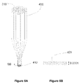
- FIG. 6 is a photograph of the cross-section of a leakage channel fiber with an ytterbium-doped core fabricated using techniques such as those disclosed above with regard to FIGS. 4A , 4 B, 5 A, and 5 B.
- FIG. 7A schematically illustrates the cross-section of a leakage of fiber such as shown in FIG. 6 .
- FIG. 7B schematically illustrates the refractive index profile across the fiber of FIG. 7A formed using ytterbium-doped rods having an average refractive index matched to that of silica, which is used to form the cladding.
- FIG. 7C schematically illustrates the refractive index profile across the fiber of FIG. 7A formed using ytterbium-doped rods having an average refractive index higher than that of silica, which is used to form the cladding.
- FIG. 7D schematically illustrates the refractive index profile across the fiber of FIG. 7A formed using ytterbium-doped rods having an average refractive index lower than that of the silica, which is used to form the cladding.
- FIG. 8 is a photo of the cross-section of a large core polarization maintaining (PM) fiber including an Yb 3+ -doped core.
- PM polarization maintaining
- FIG. 9A schematically illustrates a fiber end facet prepared by splicing with a coreless fiber.
- FIG. 9B schematically illustrates the coreless fiber of FIG. 9A cleaved to form the end facet.
- FIG. 10A schematically illustrates a fiber end facet prepared by collapsing holes in a large core fiber.
- FIG. 10B schematically illustrates the coreless fiber of FIG. 10A cleaved to form the end facet.
- FIG. 10C schematically illustrates a fiber end facet prepared by tapering and collapsing holes in a large core fiber.
- FIG. 10D schematically illustrates the tapered fiber of FIG. 10C cleaved to form the end facet.
- FIG. 11 schematically illustrates a step-index fiber design incorporating a rare earth doped core fabricated with a stack-and-draw process such as described herein with an average refractive index higher than that of the silica cladding.
- FIG. 12 schematically illustrates a polarization maintaining (PM) step-index fiber design incorporating a doped core fabricated with a stack-and-draw process such as described herein with an average refractive index higher than that of the silica cladding.
- PM polarization maintaining
- FIG. 13 schematically illustrates a bent resistant fiber design incorporating a doped core fabricated a stack-and-draw process such as described herein.
- FIG. 14 schematically illustrates a double cladding fiber formed by a process described herein.
- one limitation to scaling up power in fiber lasers includes nonlinear effects and optical damage, which are a direct consequence of tight confinement of the optical mode in the laser. Since these nonlinear effects are a direct consequence of high optical intensity in the optical fiber core, an increase of core size, which is equivalent to increase of effective mode area, can effectively reduce optical intensity and consequently the nonlinear effects.
- Multimode fibers can enable the increase of core size beyond that offered by single mode fibers.
- Multimode fibers with larger core size can be used to operate as near diffraction limited amplifiers in the presence of appropriate spatial filters and/or selective modal excitation of the fundamental mode. See, e.g., Fermann et al in U.S. Pat. No. 5,818,630, which is incorporated by reference herein in its entirety.
- Limpert et al discloses photonic crystal fibers with core diameter of ⁇ 28 ⁇ m in “High-power air-clad large-mode-area photonic crystal fiber laser” in Optics Express, vol. 11, pp. 818-823, 2003, which is incorporated by reference herein in its entirety.
- This fiber design has a large number of small holes with hole-diameter-to-hole-spacing ratio d/ ⁇ of less than 0.18 to ensure single mode propagation.
- the hole diameter d used is comparable to the wavelength of operation ⁇ with d/ ⁇ 2. At this small hole size over wavelength ratio, significant optical power penetration into the air holes takes place and this leads to severe bending sensitivity.
- This design is again limited to ⁇ 35 ⁇ m for robust fundamental mode operation, mainly due to high bend loss.
- Limpert et al discloses a rod with a photonic crystal fiber design in “Extended single-mode photonic crystal fiber lasers,” Optics Express, vol. 14, pp. 2715-2720, 2006, which is incorporated by reference herein in its entirety. Core diameters up to 100 ⁇ m with photonic crystal designs have been achieved in rods with diameter of 1.5 mm. The d/ ⁇ ratio in 100 ⁇ m core rod is 0.2. The rod structure keeps the waveguide straight and mitigates the high bending loss. Length of the rod is limited to 0.5 meters for practical reasons.
- refractive index uniformity over the doped core is preferably better than what conventional optical fiber fabrication can provide.
- index non-uniformity over the core can lead to formation of local waveguides due to local higher refractive index surrounded by lower refractive index material.
- the formation of local waveguides depends on the level of the refractive index non-uniformity as well as the geometric size of the index non-uniformity.
- Substantial refractive uniformity over the core can reduce this local waveguiding.
- the index non-uniformity is kept below few times the scale of a wavelength.
- large index non-uniformity is made smaller. Such uniformity is easier to achieve for small cores than for large cores.
- waveguiding may be formed in the core if the refractive index in the doped region of the core is higher than the undoped regions of the core.
- the core may for example, comprise silica. If the portions of the silica that are doped to provide optical gain have a higher index of refraction than undoped silica, additional local waveguiding may result. Precise index-matching of the doped and undoped regions of the core may reduce this problem. When the doped area is larger, for example with a larger effect core area, closer index matching may be more useful than if the doped region is small. Accordingly, in various embodiment described herein, the average refractive index of the doped core also is controlled to be close to that of the cladding glass, which is also used in the core. Such control of the refractive index of the doped glass can be difficult using known host materials for rare earth ions with doping levels of 3000 mol ppm and beyond.
- the desired refractive index uniformity and average refractive index can be provided by stacking fluorine-doped silica rods with lower refractive index than silica in addition to the highly ytterbium-doped rods with higher refractive index in the core and drawing the stacked rods down to produce a core rod.
- fluorine-doped silica rods with lower refractive index than silica in addition to the highly ytterbium-doped rods with higher refractive index in the core and drawing the stacked rods down to produce a core rod.
- the number of fluorine-doped rods and the number of ytterbium-doped rods are carefully chosen to give an overall average refractive index close to that of silica.
- the total number of the two types of rods is large and they are evenly distributed in a stack.
- the rods are typically stacked into a hexagonal stack and drawn down to produce a core rod.
- High degree of average refractive index control can be achieved this way. Since light cannot see structure with dimension much less than the wavelength of the light, highly uniform refractive index can be achieved when the initial individual rods are reduced to a dimension around the wavelength of the light in the final core.
- This technique reduces the level of average ytterbium doping in the final core due to the dilution from the non-ytterbium-containing fluorine-doped silica rods.
- Such fluorine doped rods may be used to achieve average refractive index, but may not contain ytterbium. This approach will lower the average ytterbium level which is used for providing gain.
- photo-darkening is a phenomenon where background loss in a fiber is permanently increased by creation of color centers as a consequence of large amount of optical power's presence in the fiber.
- Photo-darkening is generally believed to be linked to ytterbium clustering at high ytterbium doping levels, where multiple ions interact to produce photons with very high energy level to cause photo-darkening. Although the effect can be saturated after a period of exposure, it contributes to loss of output power and reduction of efficiency in fiber laser and amplifiers. Photo-darkening is more severe at high power level; it can contribute to a significant power loss in a high power fiber laser system if not dealt with appropriately.
- rare earth doped core typically has refractive index higher than that of the silica. This is especially true for highly rare earth doped core, since the required doping level for aluminum or phosphorus is higher to achieve a reasonably low level of clustering, in addition to the index increase from rare-earth-doping. Accordingly, producing highly rare earth doped core glass, which is used for the power scaling of fiber lasers in the certain large core fiber designs, that have a refractive index close to that of the silica, is particularly difficult.
- Such glasses include highly rare earth doped glass compositions having a refractive index close to that of silica.
- Such glasses can be fabricated into rods that can be used a performs to produce other rods as well as optical fiber.
- Such glasses can be fabricated with mature technologies used in the manufacture of optical fibers in telecommunications industry.
- FIG. 1 comprises a glass rod or perform 2 comprising a glass composition with high levels of rare earth ions, e.g. >1000 mol ppm, with refractive index very close to that of the silica glass, e.g. index difference ⁇ n ⁇ 1 ⁇ 10 ⁇ 3 .
- the mostly silica glass has significant levels of phosphorus, e.g., 10-50 mol % phosphorus, and boron, e.g. 8-50 mol % boron.
- the phosphorus and boron are in a phosphorus or boron containing compound.
- the mostly silica glass may, for example, comprises 5-25 mol % P 2 O 5 , and 4-25 mol % B 2 O 3 .
- An elemental analysis e.g., using a mass spectrometer or SEM, may be used to determine glass composition. It has been found that such glass compositions allow ytterbium doping levels up to 20,000 mol ppm without devitrification and enable highly efficient laser and amplifier actions. It has been discovered that photo-darkening effect is substantially lower in the fabricated fibers for equivalent amount of ytterbium doping level. The use of this glass can reduce photo-darkening and lead to much more stable and efficient high power fiber lasers and amplifiers.
- Various embodiments described herein also include techniques for fabricating doped fiber core with extremely high effective refractive index uniformity.
- This high uniformity can be achieved by fabricating a large number of rare earth doped performs having core and cladding.
- the average refractive index of the doped core glass is fabricated to be very close to that of the silica glass.
- the cladding glass of the preforms may be totally or partially removed by grinding or drilling. The result can be a rod such as shown in FIG. 1 .
- the resulting rods are stacked and the stack is drawn into a smaller size rod while ensuring substantial fusion of constituent rods in the stack.
- the stack can optionally be inserted into a tube before drawing.
- the drawn rod can be cut and re-stacked with other similar rods and drawn again following a similar procedure. This process can be repeated many times to obtain a homogenous rod at the end.
- the doped glass may be further mixed by flow and diffusion of the low viscosity rare earth doped glass at the high drawing temperature.
- an additional step may be added to fuse the structure. Part or all of the tube may then be removed by grinding or etching before drawing into rods.
- this rare earth doped glass described herein allows refractive index very close to that of the silica glass to be made. Furthermore, highly uniform rare earth doped core glass can be made by repeated stack-and-draw of the same type of glass rods instead of two types of glass rods used in other methods. This approach further improves glass uniformity and allows high effective rare-earth-doping levels in the fiber core.
- the preform fabrication technique used in the following examples is modified chemical vapor deposition (MCVD), although other known vapor deposition techniques such as, e.g., outside deposition process can also be used.
- MCVD modified chemical vapor deposition
- Silicon and phosphorus are introduced to the deposition zone through the conventional bubblers arrangement with liquid precursors, e.g., SiCl 4 and POCl 3 respectively.
- Boron is introduced into the deposition zone through a gas precursor, e.g., BCl 3 .
- Fluorine is also used and is introduced through CF 4 .
- Rare earth ions are introduced through the well known solution-doping process.
- a substrate tube 10 of 25 mm outer diameter and 19 mm inner diameter is cleaned and placed on a lathe of a MCVD system as illustrated in FIG. 2A .
- a standard MCVD system manufactured by Nextrom Technologies, Vantaa, Finland, for optical fiber manufacturing is used in this example, although other systems may be employed.
- the substrate tube 10 is joined with a starting tube 11 of similar diameter at a first end and a soot tube 12 of larger diameter at a second end.
- the starter tube 11 is held by chucks 13 and is connected to gas inlet line 16 through rotational seal 15 .
- Soot tube 12 is also held by chuck 14 .
- the soot tube 12 is connected to a scrubber which processes the exhaust gas before releasing.
- a traveling burner 17 which moves along the substrate tube 10 can heat a portion of the substrate tube at a time.
- the burner 17 reaches the end of the substrate tube 10 near the joint with the soot tube 12 , it quickly moves to the beginning of the substrate 10 near the joint with the starter tube 11 . It will be ready for next pass along the substrate tube 10 .
- the chucks 13 , 14 rotate at a rate of 40 rpm.
- the substrate tube 10 is initially cleaned with an etching pass where 200 sccm of CF 4 is used to remove a layer of glass from the inner surface of the substrate tube 10 .
- One or more optional cladding passes are used to deposit a cladding with refractive index close to the substrate tube, which may comprise silica.
- a flow of 500 sccm SiCl 4 , 300 sccm POCl 3 and 10 sccm SF 6 may be used to form a cladding.
- a core layer is deposited by moving the burner 17 upstream from the soot tube end as illustrated in FIG. 2B .
- the burner 17 moves upstream ahead of the soot formation so that the burner will not go over the core soot 20 to avoid any soot sintering as shown in FIG. 2B .
- the flow used for the core formation is 100 sccm SiCl 4 , 500 sccm POCl 3 and 200 sccm CF 4 .
- the burner 17 travels from the soot tube end to the starting tube end at 20 mm/min to encourage soot formation.
- 47 slm of hydrogen and oxygen/hydrogen ratio of 0.45 are used.
- the core layer is then followed with a pass to consolidate the core soot 20 by heating it to 1300° C.
- the substrate tube 10 is then removed from the lathe to soak the core soot 20 in YbCl 3 solution to incorporate ytterbium into the soot layers. After 1 hour of solution-doping, the solution is drained and the substrate tube 10 is placed back on the lathe. The substrate tube is dried for a few hours by passing nitrogen and heating the substrate tube up to ⁇ 1000° C.
- the core soot 20 is sintered by heating it to 1750° C. with a BCl 3 flow of 10-150 sccm. After the sintering pass, the substrate tube 10 goes through a collapse process with some level of POCl 3 over-doping, where the burner temperature is significantly raised and burner speed lowered.
- the surface tension of the tube reduces the tube outer diameter during the collapse process.
- 3-5 collapse passes are used.
- the tube is totally collapsed into a rod at the end.
- a solid preform with ytterbium-doped core is obtained.
- the boron and phosphorous are introduced at different times thereby reducing the likelihood of the reaction of boron and phosphorous in vapor phase.
- Curve 100 in FIG. 2C illustrates the refractive index profile over the core part of a fabricated ytterbium-doped preform.
- the average refractive index of this preform over the core is shown by line 101 along with the target refractive index of silica shown as line 102 .
- the average refractive index of the preform over the core shown as 101 can be made to be within ⁇ 1 ⁇ 10 ⁇ 4 of the target refractive index shown as 102 .
- An example of the average refractive index made with conventional silica host is illustrated by line 103 , which is much higher.
- the significant increase in matching is produced by the much larger amount of B 2 O 3 level incorporated in the glass, which lowered the refractive index of the doped glass.
- the core is doped with 3500-17500 mol ppm of Yb 3+ ions, giving absorption of 300-1500 dB/m at 976 nm.
- the core is further doped with 15-25 mol % of P 2 O 5 , 0.1-0.5 mol % F and 10-25 mol % B 2 O 3 .
- the photo-darkening effect is also substantially reduced in the fabricated fibers for equivalent amount of ytterbium doping level possibly at least in part because of the inclusion of phosphorus, which prevents ytterbium clustering. Variation in the parameters used to fabricate the fiber may be used and the results may also vary.
- FIG. 3A illustrates the structure of a preform 200 comprising of a core 201 , an optional deposited cladding layer 202 and silica glass layer 203 from the substrate tube 10 that may be fabricated in a process described above with reference to FIGS. 2A-2C .
- FIG. 3B further illustrates the core rod 210 made from the preform 200 by removing silica layer 203 , deposited cladding layer 202 and perhaps small part of the core 201 .
- Cross-section 211 includes all or part of core 201 .
- rod 211 contains part of the cladding layer 202 .
- the repeated stack-and-draw process starts with fabrication of multiple preforms with rare earth doped core.
- the preforms are then grinded to remove the silica layer 203 and totally or partially to remove deposited cladding layer 202 to produce multiple of core rods 210 comprises mostly rare earth doped core glass. Etching away glass layers which do not contain ytterbium and drilling out the doped core can be used for this purpose as example alternatives.
- the doped core rods 210 can then be stacked as illustrated in FIG. 4A .
- Hexagonal stack 300 shown in FIG. 4A may be used due to its high packing density, although other stacking arrangement can also be used.
- the two ends of the stack 300 are fused while the stack is held in place.
- the fused ends can then hold the shape of the stack 300 during caning. Fusing the entire stack 300 is optional.
- the doped core rods 210 can also be joined with undoped rods at one or both ends to reduce wasting doped core rods in the subsequent caning process illustrated in FIG. 4A .
- the stack 300 can then be caned into a single rod 310 by choosing appropriate drawing conditions for fusing all the rods in the stack.
- the stack 300 can also be inserted into a tube (not shown in FIG. 4A ) before drawing.
- the tube can help holding stack 300 in place during drawing.
- the caned rod 310 has a substantially fused cross-section.
- FIG. 4B show a refractive index profile 320 across a cross-section along AA shown in FIG. 4A .
- the refractive index profile 320 comprises mainly the refractive index of the original core rods 210 scaled down in dimension. Flow and diffusion can occur at higher canning temperatures. Peaks and valleys of the refractive profile of the original rods 210 can be substantially smoothed out.
- FIG. 5B shows a refractive index profile 420 along line BB of the resulting cane 410 of FIG. 5A .
- the refractive index profile 420 comprises mainly the refractive index profiles of original canes 310 scaled down in dimension.
- the refractive index profile 420 (viewed along BB) can be substantially smooth out by flow and diffusion if caning temperature is high. This can create a more uniform refractive profile.
- At least two stages are used in some embodiments as the second stage can eliminate inconsistency in the fabricated preforms.
- a stack of 37 rods are used. Other stack sizes can also be used. The number of rods used in each stage does not need to be the same. The arrangement may also vary in different embodiments.
- the stack is inserted into a tube before drawing in each stage of a two-stage process. Additionally, an extra step can be used to fuse the stack and the tube prior to drawing. The tube may then be totally or partially removed by grinding or etching. Additionally, the doped rod is incorporated into a core region of a large core fiber. Such a fiber may be fabricated by stacking the doped core together with undoped rods as well as with hollow (undoped) rods and drawing. A cross-section of a fiber 500 thereby produced is shown in FIG. 6 .
- the fiber 500 includes 6 holes 502 , which defines a core 501 .
- the 6 holes may be formed from six hollow rods used in the drawing process. Other processes and configurations may be used.
- the doped part of the core 503 comprises the doped rods fabricated by the repeated stack-and-draw process such as described above with regard to FIGS. 4A and 5A , which shows first and second stacks, respectively. Each of the rods used in the second stack are visible because the optional silica tube used in the first stack has slightly lower refractive index than that of the ytterbium-doped glass.
- silica glass is used as the matrix for the doped rods as well as for the holes 502 in the holey fiber 500 .
- silica may be used as the matrix for doped rods and/or for the holes in holey fiber.
- silica may be used as a matrix for the doped regions in the core 503 and may also be used as matrix material for creating the cladding.
- Other materials may also be used as the matrix material in other embodiments.
- different matrix materials may be used for any of the core or cladding regions, for example, to surround the doped regions (e.g., rods) or the holes in holey fiber.
- FIGS. 7A-7D illustrates various embodiments where the doped core rods are chosen to have a different average refractive index.
- FIG. 7A illustrates a leakage channel fiber 500 with 6 holes 502 , which form a core 501 . Part 503 of core 501 is made from the doped rods.
- FIGS. 7B , 7 C, and 7 D are illustrated refractive index profiles along line 504 in FIG. 7A where the doped core has an average refractive index equal to, higher than and lower, respectively, than refractive index of the silica glass used.
- FIG. 7B show a refractive index 611 of the doped part 503 of the core 501 with an average index 612 that is matched to that of the silica glass 610 .
- the refractive index 613 of air is also shown in FIG. 7B .
- FIG. 7C shows the refractive index 621 of the doped part 503 of the core 501 with an average index 622 that is higher than that of the silica glass 610 . In this case, there will be an additional waveguide due to this high average refractive index.
- V is below about 2.4 so that higher order modes are not supported in this additional waveguide.
- holes 502 can be reduced to reduce overall waveguide effect to reduce higher order mode propagation.
- the gap between holes provide leakage channels. Either hole size or/and number can be reduced to increase leakage. Higher order modes can thereby be leaked and few or single mode fiber provided.
- FIG. 7D shows the refractive index 631 of the doped part 503 of the core 501 with an average index 632 that is lower than that of the silica glass 610 .
- holes 502 can be increased to increase overall waveguide effect. Either hole size or number may be increased.
- FIG. 8 illustrates a cross-section of a polarization maintaining (PM) fiber 700 incorporating two stress elements 704 , in addition to 4 holes 702 .
- the core 701 comprises a doped portion 703 formed using doped rods such as those fabricated using processes described with reference to FIGS. 4A and 5A .
- silica glass is used as the matrix for the doped rods, the two stress elements 704 as well as for the holes 702 in the holey fiber 500 .
- silica may be used as the matrix for doped rods, stress elements, and/or for the holes in holey fiber.
- Silica may be used as a matrix for the doped regions in the core 703 and may also be used as matrix material for creating the cladding. Other materials may also be used as the matrix material in other embodiments. Additionally, different materials may be used in any of the core or cladding regions, for example, as the matrix for the doped regions (e.g., rods), the holes in holey fiber, stress elements, or other components.
- silica glass and air holes are used in the above examples, many different transparent optical media with different refractive indexes can be used to implement the design.
- a soft glass can replace silica and a different soft glass with a lower refractive index can be used to replace the air holes.
- Rare earth ions other than ytterbium can also be used. Still other variations, for example, in configuration, materials, dimensions, or in other design parameters are possible.
- a coreless fiber 802 is spliced to a large core holey fiber 801 .
- the coreless fiber 802 is then cleaved to form the end facet 810 .
- the cross-section of the cleaved end facet 810 is shown in FIG. 9B .
- Splice point 804 and holes 803 are clearly shown in FIG. 9A .
- the coreless fiber may also serve as an end cap for beam expansion if placed at the output of an amplifier.
- the end cap provides a uniform media where the beam can expand before exiting the glass. This beam expansion can advantageously reduce optical intensity at the glass/air interface to reduce or minimize end face damage.
- holes 901 in a holey fiber 900 are totally collapsed into a solid fiber 903 by heating a section of the holey fiber to a temperature at least as high as the glass softening temperature.
- the fiber 900 can then be cleaved in the collapsed portion to form an end facet 910 such as shown in FIG. 10A .
- FIG. 10B illustrates a cross-section of the collapsed and cleaved end facet 910 of a PM fiber. Stress elements 911 are visible on the fiber cross-section illustrated in FIG. 10B .
- Doped rods such as described above are also visible in the doped section 912 of the core.
- FIG. 10C illustrates a further technique where a holey fiber 920 with holes 921 is tapered and then collapsed. Drawing and/or heat can be used to create the taper and collapse the holes 921 , although the process should not be so limited.
- the holey fiber 920 has a taper 923 and a cleaved and tapered end 922 .
- the end facet 922 in this case is shown in FIG. 10D .
- This taper 923 supports smaller number of modes and can further help increase transmission loss for higher order modes, especially when placed at the input end of an amplifier. Such input taper can also help efficiently launch optical power into the core.
- the repeated stack-and-draw process described herein for making a doped core with extremely high effective refractive index uniformity can also be used in conventional step index fiber as well as photonic crystal fiber.
- the average refractive index of the doped preform core can be made to be slightly higher than that of the cladding glass.
- the doped perform may comprise, for example, doped rods that form part of the core of the fiber.
- the final rod made from the plurality of doped rods is inserted into a tube comprising the cladding glass.
- a fiber 1000 is shown in FIG. 11 , where the doped core 1001 is made from the repeated stack-and-draw process. As described above, the doped core 1001 may be formed from a plurality of doped rods.
- a cladding layer 1003 comprises cladding glass.
- the fiber 1000 is further coated with a coating 1002 .
- a refractive index profile 1004 shows the refractive index difference between the doped core and cladding glass, ⁇ n.
- the doped core having very high effective refractive index uniformity can improve mode quality and ease of use and can also allow smaller ⁇ n to be used.
- ⁇ n is chosen to be larger than 1 ⁇ 10 ⁇ 3 , affected to some extent by the refractive index uniformity, repeatability of the fabrication process, and fundamental mode bend loss. Smaller ⁇ n will allow larger core diameter to be implemented. For example, mode quality in a 30 ⁇ m core fiber can be achieved in a 50 ⁇ m core fiber if ⁇ n is reduced by a factor of (50/30) 2 ⁇ 2.8.
- single mode fiber is possible at ⁇ 1 ⁇ m wavelength for 50 ⁇ m core diameter if ⁇ n can be reduced to below 8 ⁇ 10 ⁇ 5 , e.g. a NA ⁇ 0.015, with a compromise of bending performance.
- ⁇ n can be reduced to below 8 ⁇ 10 ⁇ 5 , e.g. a NA ⁇ 0.015, with a compromise of bending performance.
- values outside these ranges are also possible.
- Stress rods 1104 can be included in the cladding 1103 of a fiber 1100 to make large core polarization maintaining (PM) fiber with a highly uniform doped core 1101 .
- An additional cladding layer with lower refractive index than that of 1103 can also be added between cladding 1103 and coating 1102 to form a pump guide in a double cladding fiber structure.
- Coating 1102 can also be chosen to be of low refractive index to form a double cladding structure. It is also possible to dope only part of the core 1101 and use a similar stack-and-draw technique to make the rest of the core with a highly uniform refractive index. Such selective doping of part of the core can be used to further improve mode selection in a fiber.
- the design in FIG. 13 can be used to improve (e.g., reduce) bending loss of large core fiber 1200 with very small NA, e.g. NA ⁇ 0.05 and weak guiding.
- a first cladding layer 1202 is placed next to a core 1201 to provide the small ⁇ n, which supports 1 to 10 modes in the partially or entirely rare earth doped core.
- the index difference between the first layer 1202 and a second layer 1203 , ⁇ n 1 can be chosen to be much larger than ⁇ n, e.g. ⁇ n 1 >1.5 ⁇ n to reduce bend loss, helped by the higher ⁇ n 1 .
- the fiber further comprises a coating 1204 surrounding the second cladding layer 1203 .
- the first cladding layer 1202 diameter, ⁇ 1 only needs to be slightly larger than core 1201 diameter, ⁇ , e.g. ⁇ 1 >1.1 ⁇ . Too large ⁇ 1 and ⁇ n can lead to large number mode being supported in the combined waveguide formed by core 1201 and the first cladding layer 1202 . Launching the fundamental mode may be difficult and inter-mode coupling may be increased if too many modes are supported by the core 1201 and first cladding 1202 . Since the mode supported in the core 1201 has better overlap with the rare earth doped core and consequently have more gain, light in modes with significant amount of power in the first cladding 1202 will be discriminated.
- a double cladding fiber 1300 is shown in FIG. 14 like the fiber in depicted in FIG. 13 , includes a core 1301 , first cladding 1302 and second cladding 1303 and a coating 1304 .
- the fiber shown in FIG. 14 further comprises third cladding layer 1305 between a second cladding layer 1303 and the coating 1304 .
- a small ⁇ n may be provided between the first cladding layer 1302 and the core 1301 to supports 1 to 10 modes in the partially or entirely rare earth doped core.
- the index difference between the first layer 1302 and a second layer 1303 , ⁇ n 1 can be chosen to be much larger than ⁇ n, e.g. ⁇ n 1 >1.5 ⁇ n to reduce bend loss, helped by the higher ⁇ n 1 .
- the first cladding layer 1302 diameter, ⁇ 1 only needs to be slightly larger than core 1301 diameter, ⁇ , e.g. ⁇ 1 >1.1 ⁇ . Too large ⁇ 1 and ⁇ n can lead to large number mode being supported in the combined waveguide formed by core 1301 and the first cladding layer 1302 . Launching the fundamental mode may be difficult and inter-mode coupling may be increased if too many modes are supported by the core 1201 and first cladding 1202 .
- the index difference between the second layer 1303 and a third layer 1305 can be chosen to be much larger than ⁇ n as well as well as larger than ⁇ n 1 in some embodiments.
- the third cladding 1305 can provide a propagation region comprising the core 1301 , first cladding 1302 , and second cladding 1303 for propagating pump radiation, for example, in a fiber amplifier or laser.
- the fibers 1200 and 1300 may have large effective area and may be doped with rare earth elements. Glass compositions having an index of refraction close to that of silica may also be used in the core as described above. Additionally, stack and draw processes such as described above may be used to provide increase uniformity in refractive index across the core. Other features and methods described herein may also be used in the fibers 1200 , 1300 shown in FIGS. 13 and 14 .
Abstract
Description
Claims (7)
Priority Applications (8)
| Application Number | Priority Date | Filing Date | Title |
|---|---|---|---|
| US11/693,633 US7450813B2 (en) | 2006-09-20 | 2007-03-29 | Rare earth doped and large effective area optical fibers for fiber lasers and amplifiers |
| EP10191210.3A EP2292566B1 (en) | 2006-09-20 | 2007-06-29 | Rare earth doped optical fibres and large effective area optical fibers for fiber lasers and amplifiers |
| DK10191210.3T DK2292566T3 (en) | 2006-09-20 | 2007-06-29 | Optical fibers doped with rare earth elements and optical fibers having large effective area for fiber lasers and amplifiers |
| EP07012846A EP1903011A3 (en) | 2006-09-20 | 2007-06-29 | Rare earth doped and large effective area optical fibers for fiber lasers and amplifiers |
| US12/246,377 US20090123121A1 (en) | 2006-09-20 | 2008-10-06 | Rare earth doped and large effective area optical fibers for fiber lasers and amplifiers |
| US12/789,931 US8213758B2 (en) | 2006-09-20 | 2010-05-28 | Rare earth doped and large effective area optical fibers for fiber lasers and amplifiers |
| US13/493,264 US8542968B2 (en) | 2006-09-20 | 2012-06-11 | Rare earth doped and large effective area optical fibers for fiber lasers and amplifiers |
| US14/023,824 US9151889B2 (en) | 2006-09-20 | 2013-09-11 | Rare earth doped and large effective area optical fibers for fiber lasers and amplifiers |
Applications Claiming Priority (2)
| Application Number | Priority Date | Filing Date | Title |
|---|---|---|---|
| US84601206P | 2006-09-20 | 2006-09-20 | |
| US11/693,633 US7450813B2 (en) | 2006-09-20 | 2007-03-29 | Rare earth doped and large effective area optical fibers for fiber lasers and amplifiers |
Related Child Applications (1)
| Application Number | Title | Priority Date | Filing Date |
|---|---|---|---|
| US12/246,377 Division US20090123121A1 (en) | 2006-09-20 | 2008-10-06 | Rare earth doped and large effective area optical fibers for fiber lasers and amplifiers |
Publications (2)
| Publication Number | Publication Date |
|---|---|
| US20080069508A1 US20080069508A1 (en) | 2008-03-20 |
| US7450813B2 true US7450813B2 (en) | 2008-11-11 |
Family
ID=38893320
Family Applications (5)
| Application Number | Title | Priority Date | Filing Date |
|---|---|---|---|
| US11/693,633 Expired - Fee Related US7450813B2 (en) | 2006-09-20 | 2007-03-29 | Rare earth doped and large effective area optical fibers for fiber lasers and amplifiers |
| US12/246,377 Abandoned US20090123121A1 (en) | 2006-09-20 | 2008-10-06 | Rare earth doped and large effective area optical fibers for fiber lasers and amplifiers |
| US12/789,931 Expired - Fee Related US8213758B2 (en) | 2006-09-20 | 2010-05-28 | Rare earth doped and large effective area optical fibers for fiber lasers and amplifiers |
| US13/493,264 Expired - Fee Related US8542968B2 (en) | 2006-09-20 | 2012-06-11 | Rare earth doped and large effective area optical fibers for fiber lasers and amplifiers |
| US14/023,824 Expired - Fee Related US9151889B2 (en) | 2006-09-20 | 2013-09-11 | Rare earth doped and large effective area optical fibers for fiber lasers and amplifiers |
Family Applications After (4)
| Application Number | Title | Priority Date | Filing Date |
|---|---|---|---|
| US12/246,377 Abandoned US20090123121A1 (en) | 2006-09-20 | 2008-10-06 | Rare earth doped and large effective area optical fibers for fiber lasers and amplifiers |
| US12/789,931 Expired - Fee Related US8213758B2 (en) | 2006-09-20 | 2010-05-28 | Rare earth doped and large effective area optical fibers for fiber lasers and amplifiers |
| US13/493,264 Expired - Fee Related US8542968B2 (en) | 2006-09-20 | 2012-06-11 | Rare earth doped and large effective area optical fibers for fiber lasers and amplifiers |
| US14/023,824 Expired - Fee Related US9151889B2 (en) | 2006-09-20 | 2013-09-11 | Rare earth doped and large effective area optical fibers for fiber lasers and amplifiers |
Country Status (3)
| Country | Link |
|---|---|
| US (5) | US7450813B2 (en) |
| EP (2) | EP2292566B1 (en) |
| DK (1) | DK2292566T3 (en) |
Cited By (11)
| Publication number | Priority date | Publication date | Assignee | Title |
|---|---|---|---|---|
| US20090123121A1 (en) * | 2006-09-20 | 2009-05-14 | Imra America, Inc. | Rare earth doped and large effective area optical fibers for fiber lasers and amplifiers |
| US20100079855A1 (en) * | 2008-04-22 | 2010-04-01 | Liang Dong | Multi-clad optical fibers |
| WO2010065788A1 (en) * | 2008-12-04 | 2010-06-10 | Imra America, Inc. | Highly rare-earth-doped optical fibers for fiber lasers and amplifiers |
| US20100225897A1 (en) * | 2009-03-06 | 2010-09-09 | Imra America, Inc. | Optical scanning and imaging systems based on dual pulsed laser systems |
| US20100247912A1 (en) * | 2009-03-24 | 2010-09-30 | Gapontsev Valentin P | Method for Manufacturing LMA Optical Preforms and Fibers |
| US20110080580A1 (en) * | 2006-03-10 | 2011-04-07 | Imra America, Inc. | Optical signal processing with modelocked lasers |
| CN102010121A (en) * | 2010-11-05 | 2011-04-13 | 北京交通大学 | Quartz rod structure for changing refractive index profile by external exposure method |
| CN102025098A (en) * | 2010-11-19 | 2011-04-20 | 北京交通大学 | Large-effective mode field area single-mode laser with exposure area in active quartz rod |
| US8849083B1 (en) | 2011-04-28 | 2014-09-30 | Nufern | All glass leakage channel fibers and devices using them |
| WO2015077021A1 (en) | 2013-11-22 | 2015-05-28 | Imra America, Inc | Polarizing and polarization maintaining leakage channel fibers |
| CN109956664A (en) * | 2017-12-22 | 2019-07-02 | 中国科学院上海光学精密机械研究所 | The method for improving rear-earth-doped quartz glass bar uniformity |
Families Citing this family (185)
| Publication number | Priority date | Publication date | Assignee | Title |
|---|---|---|---|---|
| ES2332340B1 (en) * | 2006-12-26 | 2011-05-27 | Institut De Ciencies Fotoniques, Fundacio Privada | OPTICAL FIBER INMTERFEROMETER. |
| US8055115B2 (en) * | 2007-07-05 | 2011-11-08 | Coractive High-Tech Inc. | Optically active glass and optical fiber with reduced photodarkening and method for reducing photodarkening |
| US8414186B2 (en) * | 2007-07-20 | 2013-04-09 | Sensortran, Inc. | Pure silica core multimode fiber sensors for DTS applications |
| US8970947B2 (en) * | 2007-09-26 | 2015-03-03 | Imra America, Inc. | Auto-cladded multi-core optical fibers |
| JP5744380B2 (en) * | 2009-03-26 | 2015-07-08 | 株式会社フジクラ | Optical fiber |
| US8971682B2 (en) | 2012-03-01 | 2015-03-03 | Corning Incorporated | Few mode optical fibers |
| US10009065B2 (en) | 2012-12-05 | 2018-06-26 | At&T Intellectual Property I, L.P. | Backhaul link for distributed antenna system |
| US9113347B2 (en) | 2012-12-05 | 2015-08-18 | At&T Intellectual Property I, Lp | Backhaul link for distributed antenna system |
| US9525524B2 (en) | 2013-05-31 | 2016-12-20 | At&T Intellectual Property I, L.P. | Remote distributed antenna system |
| US9999038B2 (en) | 2013-05-31 | 2018-06-12 | At&T Intellectual Property I, L.P. | Remote distributed antenna system |
| GB2516088A (en) * | 2013-07-11 | 2015-01-14 | Fibercore Ltd | Optical Fiber |
| EP3025175B1 (en) * | 2013-07-25 | 2019-11-20 | B.G. Negev Technologies & Applications Ltd., at Ben-Gurion University | Single large mode cladding amplification in active double-clad fibers |
| US8897697B1 (en) | 2013-11-06 | 2014-11-25 | At&T Intellectual Property I, Lp | Millimeter-wave surface-wave communications |
| US9209902B2 (en) | 2013-12-10 | 2015-12-08 | At&T Intellectual Property I, L.P. | Quasi-optical coupler |
| NL2012868B1 (en) * | 2014-05-22 | 2016-03-15 | Draka Comteq Bv | A method for manufacturing an optical preform. |
| US9692101B2 (en) | 2014-08-26 | 2017-06-27 | At&T Intellectual Property I, L.P. | Guided wave couplers for coupling electromagnetic waves between a waveguide surface and a surface of a wire |
| US9768833B2 (en) | 2014-09-15 | 2017-09-19 | At&T Intellectual Property I, L.P. | Method and apparatus for sensing a condition in a transmission medium of electromagnetic waves |
| US10063280B2 (en) | 2014-09-17 | 2018-08-28 | At&T Intellectual Property I, L.P. | Monitoring and mitigating conditions in a communication network |
| US9628854B2 (en) | 2014-09-29 | 2017-04-18 | At&T Intellectual Property I, L.P. | Method and apparatus for distributing content in a communication network |
| US9615269B2 (en) | 2014-10-02 | 2017-04-04 | At&T Intellectual Property I, L.P. | Method and apparatus that provides fault tolerance in a communication network |
| US9685992B2 (en) | 2014-10-03 | 2017-06-20 | At&T Intellectual Property I, L.P. | Circuit panel network and methods thereof |
| US9503189B2 (en) | 2014-10-10 | 2016-11-22 | At&T Intellectual Property I, L.P. | Method and apparatus for arranging communication sessions in a communication system |
| US9762289B2 (en) | 2014-10-14 | 2017-09-12 | At&T Intellectual Property I, L.P. | Method and apparatus for transmitting or receiving signals in a transportation system |
| US9973299B2 (en) | 2014-10-14 | 2018-05-15 | At&T Intellectual Property I, L.P. | Method and apparatus for adjusting a mode of communication in a communication network |
| US9312919B1 (en) | 2014-10-21 | 2016-04-12 | At&T Intellectual Property I, Lp | Transmission device with impairment compensation and methods for use therewith |
| US9564947B2 (en) | 2014-10-21 | 2017-02-07 | At&T Intellectual Property I, L.P. | Guided-wave transmission device with diversity and methods for use therewith |
| US9769020B2 (en) | 2014-10-21 | 2017-09-19 | At&T Intellectual Property I, L.P. | Method and apparatus for responding to events affecting communications in a communication network |
| US9520945B2 (en) | 2014-10-21 | 2016-12-13 | At&T Intellectual Property I, L.P. | Apparatus for providing communication services and methods thereof |
| US9577306B2 (en) | 2014-10-21 | 2017-02-21 | At&T Intellectual Property I, L.P. | Guided-wave transmission device and methods for use therewith |
| US9653770B2 (en) | 2014-10-21 | 2017-05-16 | At&T Intellectual Property I, L.P. | Guided wave coupler, coupling module and methods for use therewith |
| US9627768B2 (en) | 2014-10-21 | 2017-04-18 | At&T Intellectual Property I, L.P. | Guided-wave transmission device with non-fundamental mode propagation and methods for use therewith |
| US9780834B2 (en) | 2014-10-21 | 2017-10-03 | At&T Intellectual Property I, L.P. | Method and apparatus for transmitting electromagnetic waves |
| US10340573B2 (en) | 2016-10-26 | 2019-07-02 | At&T Intellectual Property I, L.P. | Launcher with cylindrical coupling device and methods for use therewith |
| US10009067B2 (en) | 2014-12-04 | 2018-06-26 | At&T Intellectual Property I, L.P. | Method and apparatus for configuring a communication interface |
| US9680670B2 (en) | 2014-11-20 | 2017-06-13 | At&T Intellectual Property I, L.P. | Transmission device with channel equalization and control and methods for use therewith |
| US9954287B2 (en) | 2014-11-20 | 2018-04-24 | At&T Intellectual Property I, L.P. | Apparatus for converting wireless signals and electromagnetic waves and methods thereof |
| US9800327B2 (en) | 2014-11-20 | 2017-10-24 | At&T Intellectual Property I, L.P. | Apparatus for controlling operations of a communication device and methods thereof |
| US9461706B1 (en) | 2015-07-31 | 2016-10-04 | At&T Intellectual Property I, Lp | Method and apparatus for exchanging communication signals |
| US9742462B2 (en) | 2014-12-04 | 2017-08-22 | At&T Intellectual Property I, L.P. | Transmission medium and communication interfaces and methods for use therewith |
| US9997819B2 (en) | 2015-06-09 | 2018-06-12 | At&T Intellectual Property I, L.P. | Transmission medium and method for facilitating propagation of electromagnetic waves via a core |
| US9544006B2 (en) | 2014-11-20 | 2017-01-10 | At&T Intellectual Property I, L.P. | Transmission device with mode division multiplexing and methods for use therewith |
| US10243784B2 (en) | 2014-11-20 | 2019-03-26 | At&T Intellectual Property I, L.P. | System for generating topology information and methods thereof |
| US9654173B2 (en) | 2014-11-20 | 2017-05-16 | At&T Intellectual Property I, L.P. | Apparatus for powering a communication device and methods thereof |
| US10144036B2 (en) | 2015-01-30 | 2018-12-04 | At&T Intellectual Property I, L.P. | Method and apparatus for mitigating interference affecting a propagation of electromagnetic waves guided by a transmission medium |
| US9876570B2 (en) | 2015-02-20 | 2018-01-23 | At&T Intellectual Property I, Lp | Guided-wave transmission device with non-fundamental mode propagation and methods for use therewith |
| US9749013B2 (en) | 2015-03-17 | 2017-08-29 | At&T Intellectual Property I, L.P. | Method and apparatus for reducing attenuation of electromagnetic waves guided by a transmission medium |
| US9705561B2 (en) | 2015-04-24 | 2017-07-11 | At&T Intellectual Property I, L.P. | Directional coupling device and methods for use therewith |
| US10224981B2 (en) | 2015-04-24 | 2019-03-05 | At&T Intellectual Property I, Lp | Passive electrical coupling device and methods for use therewith |
| US9948354B2 (en) | 2015-04-28 | 2018-04-17 | At&T Intellectual Property I, L.P. | Magnetic coupling device with reflective plate and methods for use therewith |
| US9793954B2 (en) | 2015-04-28 | 2017-10-17 | At&T Intellectual Property I, L.P. | Magnetic coupling device and methods for use therewith |
| US9490869B1 (en) | 2015-05-14 | 2016-11-08 | At&T Intellectual Property I, L.P. | Transmission medium having multiple cores and methods for use therewith |
| US9748626B2 (en) | 2015-05-14 | 2017-08-29 | At&T Intellectual Property I, L.P. | Plurality of cables having different cross-sectional shapes which are bundled together to form a transmission medium |
| US9871282B2 (en) | 2015-05-14 | 2018-01-16 | At&T Intellectual Property I, L.P. | At least one transmission medium having a dielectric surface that is covered at least in part by a second dielectric |
| US10650940B2 (en) | 2015-05-15 | 2020-05-12 | At&T Intellectual Property I, L.P. | Transmission medium having a conductive material and methods for use therewith |
| US10679767B2 (en) | 2015-05-15 | 2020-06-09 | At&T Intellectual Property I, L.P. | Transmission medium having a conductive material and methods for use therewith |
| US9917341B2 (en) | 2015-05-27 | 2018-03-13 | At&T Intellectual Property I, L.P. | Apparatus and method for launching electromagnetic waves and for modifying radial dimensions of the propagating electromagnetic waves |
| EP3128351A4 (en) * | 2015-06-01 | 2017-06-21 | Wuhan Brightcore Optical Fiber Co., Ltd. | Polarization-maintaining gain optical fiber having elliptical cladding and large mode field diameter |
| US9912381B2 (en) | 2015-06-03 | 2018-03-06 | At&T Intellectual Property I, Lp | Network termination and methods for use therewith |
| US10348391B2 (en) | 2015-06-03 | 2019-07-09 | At&T Intellectual Property I, L.P. | Client node device with frequency conversion and methods for use therewith |
| US10154493B2 (en) | 2015-06-03 | 2018-12-11 | At&T Intellectual Property I, L.P. | Network termination and methods for use therewith |
| US9866309B2 (en) | 2015-06-03 | 2018-01-09 | At&T Intellectual Property I, Lp | Host node device and methods for use therewith |
| US10812174B2 (en) | 2015-06-03 | 2020-10-20 | At&T Intellectual Property I, L.P. | Client node device and methods for use therewith |
| US10103801B2 (en) | 2015-06-03 | 2018-10-16 | At&T Intellectual Property I, L.P. | Host node device and methods for use therewith |
| US9913139B2 (en) | 2015-06-09 | 2018-03-06 | At&T Intellectual Property I, L.P. | Signal fingerprinting for authentication of communicating devices |
| US10142086B2 (en) | 2015-06-11 | 2018-11-27 | At&T Intellectual Property I, L.P. | Repeater and methods for use therewith |
| US9608692B2 (en) | 2015-06-11 | 2017-03-28 | At&T Intellectual Property I, L.P. | Repeater and methods for use therewith |
| US9820146B2 (en) | 2015-06-12 | 2017-11-14 | At&T Intellectual Property I, L.P. | Method and apparatus for authentication and identity management of communicating devices |
| US9667317B2 (en) | 2015-06-15 | 2017-05-30 | At&T Intellectual Property I, L.P. | Method and apparatus for providing security using network traffic adjustments |
| US9509415B1 (en) | 2015-06-25 | 2016-11-29 | At&T Intellectual Property I, L.P. | Methods and apparatus for inducing a fundamental wave mode on a transmission medium |
| US9865911B2 (en) | 2015-06-25 | 2018-01-09 | At&T Intellectual Property I, L.P. | Waveguide system for slot radiating first electromagnetic waves that are combined into a non-fundamental wave mode second electromagnetic wave on a transmission medium |
| US9640850B2 (en) | 2015-06-25 | 2017-05-02 | At&T Intellectual Property I, L.P. | Methods and apparatus for inducing a non-fundamental wave mode on a transmission medium |
| US10033107B2 (en) | 2015-07-14 | 2018-07-24 | At&T Intellectual Property I, L.P. | Method and apparatus for coupling an antenna to a device |
| US9882257B2 (en) | 2015-07-14 | 2018-01-30 | At&T Intellectual Property I, L.P. | Method and apparatus for launching a wave mode that mitigates interference |
| US10148016B2 (en) | 2015-07-14 | 2018-12-04 | At&T Intellectual Property I, L.P. | Apparatus and methods for communicating utilizing an antenna array |
| US10033108B2 (en) | 2015-07-14 | 2018-07-24 | At&T Intellectual Property I, L.P. | Apparatus and methods for generating an electromagnetic wave having a wave mode that mitigates interference |
| US10205655B2 (en) | 2015-07-14 | 2019-02-12 | At&T Intellectual Property I, L.P. | Apparatus and methods for communicating utilizing an antenna array and multiple communication paths |
| US9853342B2 (en) | 2015-07-14 | 2017-12-26 | At&T Intellectual Property I, L.P. | Dielectric transmission medium connector and methods for use therewith |
| US9722318B2 (en) | 2015-07-14 | 2017-08-01 | At&T Intellectual Property I, L.P. | Method and apparatus for coupling an antenna to a device |
| US9847566B2 (en) | 2015-07-14 | 2017-12-19 | At&T Intellectual Property I, L.P. | Method and apparatus for adjusting a field of a signal to mitigate interference |
| US10170840B2 (en) | 2015-07-14 | 2019-01-01 | At&T Intellectual Property I, L.P. | Apparatus and methods for sending or receiving electromagnetic signals |
| US10341142B2 (en) | 2015-07-14 | 2019-07-02 | At&T Intellectual Property I, L.P. | Apparatus and methods for generating non-interfering electromagnetic waves on an uninsulated conductor |
| US9836957B2 (en) | 2015-07-14 | 2017-12-05 | At&T Intellectual Property I, L.P. | Method and apparatus for communicating with premises equipment |
| US10044409B2 (en) | 2015-07-14 | 2018-08-07 | At&T Intellectual Property I, L.P. | Transmission medium and methods for use therewith |
| US10320586B2 (en) | 2015-07-14 | 2019-06-11 | At&T Intellectual Property I, L.P. | Apparatus and methods for generating non-interfering electromagnetic waves on an insulated transmission medium |
| US9628116B2 (en) | 2015-07-14 | 2017-04-18 | At&T Intellectual Property I, L.P. | Apparatus and methods for transmitting wireless signals |
| US9793951B2 (en) | 2015-07-15 | 2017-10-17 | At&T Intellectual Property I, L.P. | Method and apparatus for launching a wave mode that mitigates interference |
| US10090606B2 (en) | 2015-07-15 | 2018-10-02 | At&T Intellectual Property I, L.P. | Antenna system with dielectric array and methods for use therewith |
| US9608740B2 (en) | 2015-07-15 | 2017-03-28 | At&T Intellectual Property I, L.P. | Method and apparatus for launching a wave mode that mitigates interference |
| US9948333B2 (en) | 2015-07-23 | 2018-04-17 | At&T Intellectual Property I, L.P. | Method and apparatus for wireless communications to mitigate interference |
| US9871283B2 (en) | 2015-07-23 | 2018-01-16 | At&T Intellectual Property I, Lp | Transmission medium having a dielectric core comprised of plural members connected by a ball and socket configuration |
| US9749053B2 (en) | 2015-07-23 | 2017-08-29 | At&T Intellectual Property I, L.P. | Node device, repeater and methods for use therewith |
| US10784670B2 (en) | 2015-07-23 | 2020-09-22 | At&T Intellectual Property I, L.P. | Antenna support for aligning an antenna |
| US9912027B2 (en) | 2015-07-23 | 2018-03-06 | At&T Intellectual Property I, L.P. | Method and apparatus for exchanging communication signals |
| US10020587B2 (en) | 2015-07-31 | 2018-07-10 | At&T Intellectual Property I, L.P. | Radial antenna and methods for use therewith |
| US9967173B2 (en) | 2015-07-31 | 2018-05-08 | At&T Intellectual Property I, L.P. | Method and apparatus for authentication and identity management of communicating devices |
| US9735833B2 (en) | 2015-07-31 | 2017-08-15 | At&T Intellectual Property I, L.P. | Method and apparatus for communications management in a neighborhood network |
| US9904535B2 (en) | 2015-09-14 | 2018-02-27 | At&T Intellectual Property I, L.P. | Method and apparatus for distributing software |
| US9705571B2 (en) | 2015-09-16 | 2017-07-11 | At&T Intellectual Property I, L.P. | Method and apparatus for use with a radio distributed antenna system |
| US10079661B2 (en) | 2015-09-16 | 2018-09-18 | At&T Intellectual Property I, L.P. | Method and apparatus for use with a radio distributed antenna system having a clock reference |
| US10051629B2 (en) | 2015-09-16 | 2018-08-14 | At&T Intellectual Property I, L.P. | Method and apparatus for use with a radio distributed antenna system having an in-band reference signal |
| US10009901B2 (en) | 2015-09-16 | 2018-06-26 | At&T Intellectual Property I, L.P. | Method, apparatus, and computer-readable storage medium for managing utilization of wireless resources between base stations |
| US10009063B2 (en) | 2015-09-16 | 2018-06-26 | At&T Intellectual Property I, L.P. | Method and apparatus for use with a radio distributed antenna system having an out-of-band reference signal |
| US10136434B2 (en) | 2015-09-16 | 2018-11-20 | At&T Intellectual Property I, L.P. | Method and apparatus for use with a radio distributed antenna system having an ultra-wideband control channel |
| US9769128B2 (en) | 2015-09-28 | 2017-09-19 | At&T Intellectual Property I, L.P. | Method and apparatus for encryption of communications over a network |
| US9729197B2 (en) | 2015-10-01 | 2017-08-08 | At&T Intellectual Property I, L.P. | Method and apparatus for communicating network management traffic over a network |
| US9882277B2 (en) | 2015-10-02 | 2018-01-30 | At&T Intellectual Property I, Lp | Communication device and antenna assembly with actuated gimbal mount |
| US9876264B2 (en) | 2015-10-02 | 2018-01-23 | At&T Intellectual Property I, Lp | Communication system, guided wave switch and methods for use therewith |
| US10074890B2 (en) | 2015-10-02 | 2018-09-11 | At&T Intellectual Property I, L.P. | Communication device and antenna with integrated light assembly |
| US10665942B2 (en) | 2015-10-16 | 2020-05-26 | At&T Intellectual Property I, L.P. | Method and apparatus for adjusting wireless communications |
| US10355367B2 (en) | 2015-10-16 | 2019-07-16 | At&T Intellectual Property I, L.P. | Antenna structure for exchanging wireless signals |
| US10051483B2 (en) | 2015-10-16 | 2018-08-14 | At&T Intellectual Property I, L.P. | Method and apparatus for directing wireless signals |
| US9857529B2 (en) | 2016-01-29 | 2018-01-02 | Corning Incorporated | Optical fiber span with low differential mode delay |
| KR101949358B1 (en) * | 2016-04-04 | 2019-02-18 | 엘지전자 주식회사 | Apparatus for providing around view and Vehicle including the same |
| CN107306005A (en) * | 2016-04-21 | 2017-10-31 | 国神光电科技(上海)有限公司 | A kind of optical fiber laser amplifier and the method and system for reducing its spontaneous radiation |
| US9912419B1 (en) | 2016-08-24 | 2018-03-06 | At&T Intellectual Property I, L.P. | Method and apparatus for managing a fault in a distributed antenna system |
| US9860075B1 (en) | 2016-08-26 | 2018-01-02 | At&T Intellectual Property I, L.P. | Method and communication node for broadband distribution |
| US10291311B2 (en) | 2016-09-09 | 2019-05-14 | At&T Intellectual Property I, L.P. | Method and apparatus for mitigating a fault in a distributed antenna system |
| US11032819B2 (en) | 2016-09-15 | 2021-06-08 | At&T Intellectual Property I, L.P. | Method and apparatus for use with a radio distributed antenna system having a control channel reference signal |
| US10135147B2 (en) | 2016-10-18 | 2018-11-20 | At&T Intellectual Property I, L.P. | Apparatus and methods for launching guided waves via an antenna |
| US10135146B2 (en) | 2016-10-18 | 2018-11-20 | At&T Intellectual Property I, L.P. | Apparatus and methods for launching guided waves via circuits |
| US10340600B2 (en) | 2016-10-18 | 2019-07-02 | At&T Intellectual Property I, L.P. | Apparatus and methods for launching guided waves via plural waveguide systems |
| US9876605B1 (en) | 2016-10-21 | 2018-01-23 | At&T Intellectual Property I, L.P. | Launcher and coupling system to support desired guided wave mode |
| WO2018074511A1 (en) * | 2016-10-21 | 2018-04-26 | 株式会社フジクラ | Fiber laser device |
| US9991580B2 (en) | 2016-10-21 | 2018-06-05 | At&T Intellectual Property I, L.P. | Launcher and coupling system for guided wave mode cancellation |
| US10374316B2 (en) | 2016-10-21 | 2019-08-06 | At&T Intellectual Property I, L.P. | System and dielectric antenna with non-uniform dielectric |
| US10811767B2 (en) | 2016-10-21 | 2020-10-20 | At&T Intellectual Property I, L.P. | System and dielectric antenna with convex dielectric radome |
| US10312567B2 (en) | 2016-10-26 | 2019-06-04 | At&T Intellectual Property I, L.P. | Launcher with planar strip antenna and methods for use therewith |
| US10224634B2 (en) | 2016-11-03 | 2019-03-05 | At&T Intellectual Property I, L.P. | Methods and apparatus for adjusting an operational characteristic of an antenna |
| US10225025B2 (en) | 2016-11-03 | 2019-03-05 | At&T Intellectual Property I, L.P. | Method and apparatus for detecting a fault in a communication system |
| US10291334B2 (en) | 2016-11-03 | 2019-05-14 | At&T Intellectual Property I, L.P. | System for detecting a fault in a communication system |
| US10498044B2 (en) | 2016-11-03 | 2019-12-03 | At&T Intellectual Property I, L.P. | Apparatus for configuring a surface of an antenna |
| US10090594B2 (en) | 2016-11-23 | 2018-10-02 | At&T Intellectual Property I, L.P. | Antenna system having structural configurations for assembly |
| US10340601B2 (en) | 2016-11-23 | 2019-07-02 | At&T Intellectual Property I, L.P. | Multi-antenna system and methods for use therewith |
| US10535928B2 (en) | 2016-11-23 | 2020-01-14 | At&T Intellectual Property I, L.P. | Antenna system and methods for use therewith |
| US10178445B2 (en) | 2016-11-23 | 2019-01-08 | At&T Intellectual Property I, L.P. | Methods, devices, and systems for load balancing between a plurality of waveguides |
| US10340603B2 (en) | 2016-11-23 | 2019-07-02 | At&T Intellectual Property I, L.P. | Antenna system having shielded structural configurations for assembly |
| US10305190B2 (en) | 2016-12-01 | 2019-05-28 | At&T Intellectual Property I, L.P. | Reflecting dielectric antenna system and methods for use therewith |
| US10361489B2 (en) | 2016-12-01 | 2019-07-23 | At&T Intellectual Property I, L.P. | Dielectric dish antenna system and methods for use therewith |
| US10755542B2 (en) | 2016-12-06 | 2020-08-25 | At&T Intellectual Property I, L.P. | Method and apparatus for surveillance via guided wave communication |
| US9927517B1 (en) | 2016-12-06 | 2018-03-27 | At&T Intellectual Property I, L.P. | Apparatus and methods for sensing rainfall |
| US10727599B2 (en) | 2016-12-06 | 2020-07-28 | At&T Intellectual Property I, L.P. | Launcher with slot antenna and methods for use therewith |
| US10382976B2 (en) | 2016-12-06 | 2019-08-13 | At&T Intellectual Property I, L.P. | Method and apparatus for managing wireless communications based on communication paths and network device positions |
| US10637149B2 (en) | 2016-12-06 | 2020-04-28 | At&T Intellectual Property I, L.P. | Injection molded dielectric antenna and methods for use therewith |
| US10135145B2 (en) | 2016-12-06 | 2018-11-20 | At&T Intellectual Property I, L.P. | Apparatus and methods for generating an electromagnetic wave along a transmission medium |
| US10439675B2 (en) | 2016-12-06 | 2019-10-08 | At&T Intellectual Property I, L.P. | Method and apparatus for repeating guided wave communication signals |
| US10694379B2 (en) | 2016-12-06 | 2020-06-23 | At&T Intellectual Property I, L.P. | Waveguide system with device-based authentication and methods for use therewith |
| US10020844B2 (en) | 2016-12-06 | 2018-07-10 | T&T Intellectual Property I, L.P. | Method and apparatus for broadcast communication via guided waves |
| US10819035B2 (en) | 2016-12-06 | 2020-10-27 | At&T Intellectual Property I, L.P. | Launcher with helical antenna and methods for use therewith |
| US10326494B2 (en) | 2016-12-06 | 2019-06-18 | At&T Intellectual Property I, L.P. | Apparatus for measurement de-embedding and methods for use therewith |
| US10547348B2 (en) | 2016-12-07 | 2020-01-28 | At&T Intellectual Property I, L.P. | Method and apparatus for switching transmission mediums in a communication system |
| US10389029B2 (en) | 2016-12-07 | 2019-08-20 | At&T Intellectual Property I, L.P. | Multi-feed dielectric antenna system with core selection and methods for use therewith |
| US10359749B2 (en) | 2016-12-07 | 2019-07-23 | At&T Intellectual Property I, L.P. | Method and apparatus for utilities management via guided wave communication |
| US10139820B2 (en) | 2016-12-07 | 2018-11-27 | At&T Intellectual Property I, L.P. | Method and apparatus for deploying equipment of a communication system |
| US10446936B2 (en) | 2016-12-07 | 2019-10-15 | At&T Intellectual Property I, L.P. | Multi-feed dielectric antenna system and methods for use therewith |
| US10168695B2 (en) | 2016-12-07 | 2019-01-01 | At&T Intellectual Property I, L.P. | Method and apparatus for controlling an unmanned aircraft |
| US10243270B2 (en) | 2016-12-07 | 2019-03-26 | At&T Intellectual Property I, L.P. | Beam adaptive multi-feed dielectric antenna system and methods for use therewith |
| US9893795B1 (en) | 2016-12-07 | 2018-02-13 | At&T Intellectual Property I, Lp | Method and repeater for broadband distribution |
| US10027397B2 (en) | 2016-12-07 | 2018-07-17 | At&T Intellectual Property I, L.P. | Distributed antenna system and methods for use therewith |
| US10777873B2 (en) | 2016-12-08 | 2020-09-15 | At&T Intellectual Property I, L.P. | Method and apparatus for mounting network devices |
| US10601494B2 (en) | 2016-12-08 | 2020-03-24 | At&T Intellectual Property I, L.P. | Dual-band communication device and method for use therewith |
| US10069535B2 (en) | 2016-12-08 | 2018-09-04 | At&T Intellectual Property I, L.P. | Apparatus and methods for launching electromagnetic waves having a certain electric field structure |
| US9911020B1 (en) | 2016-12-08 | 2018-03-06 | At&T Intellectual Property I, L.P. | Method and apparatus for tracking via a radio frequency identification device |
| US9998870B1 (en) | 2016-12-08 | 2018-06-12 | At&T Intellectual Property I, L.P. | Method and apparatus for proximity sensing |
| US10103422B2 (en) | 2016-12-08 | 2018-10-16 | At&T Intellectual Property I, L.P. | Method and apparatus for mounting network devices |
| US10389037B2 (en) | 2016-12-08 | 2019-08-20 | At&T Intellectual Property I, L.P. | Apparatus and methods for selecting sections of an antenna array and use therewith |
| US10530505B2 (en) | 2016-12-08 | 2020-01-07 | At&T Intellectual Property I, L.P. | Apparatus and methods for launching electromagnetic waves along a transmission medium |
| US10411356B2 (en) | 2016-12-08 | 2019-09-10 | At&T Intellectual Property I, L.P. | Apparatus and methods for selectively targeting communication devices with an antenna array |
| US10916969B2 (en) | 2016-12-08 | 2021-02-09 | At&T Intellectual Property I, L.P. | Method and apparatus for providing power using an inductive coupling |
| US10326689B2 (en) | 2016-12-08 | 2019-06-18 | At&T Intellectual Property I, L.P. | Method and system for providing alternative communication paths |
| US10938108B2 (en) | 2016-12-08 | 2021-03-02 | At&T Intellectual Property I, L.P. | Frequency selective multi-feed dielectric antenna system and methods for use therewith |
| US9838896B1 (en) | 2016-12-09 | 2017-12-05 | At&T Intellectual Property I, L.P. | Method and apparatus for assessing network coverage |
| US10264586B2 (en) | 2016-12-09 | 2019-04-16 | At&T Mobility Ii Llc | Cloud-based packet controller and methods for use therewith |
| US10340983B2 (en) | 2016-12-09 | 2019-07-02 | At&T Intellectual Property I, L.P. | Method and apparatus for surveying remote sites via guided wave communications |
| US11156769B2 (en) * | 2016-12-14 | 2021-10-26 | Ofs Fitel, Llc | Polarization-maintaining fiber device supporting propagation in large mode field diameters |
| KR20190104221A (en) * | 2017-01-24 | 2019-09-06 | 코닝 인코포레이티드 | Optical fibers and optical systems comprising the same |
| US9973940B1 (en) | 2017-02-27 | 2018-05-15 | At&T Intellectual Property I, L.P. | Apparatus and methods for dynamic impedance matching of a guided wave launcher |
| US10298293B2 (en) | 2017-03-13 | 2019-05-21 | At&T Intellectual Property I, L.P. | Apparatus of communication utilizing wireless network devices |
| CN107065066B (en) * | 2017-05-19 | 2019-10-18 | 中国科学院上海光学精密机械研究所 | A kind of structure of more clad silica fibers |
| EP3639071A4 (en) * | 2017-06-16 | 2020-06-03 | Intuitive Surgical Operations Inc. | Optical fiber with integrated absorber material |
| CN107935371A (en) * | 2017-12-11 | 2018-04-20 | 中国电子科技集团公司第四十六研究所 | A kind of method for preparing rare earth doped fiber plug prefabricated rods |
| CN111527429A (en) * | 2017-12-28 | 2020-08-11 | 株式会社藤仓 | Optical fiber and laser device |
| CN108761634B (en) * | 2018-03-26 | 2020-05-22 | 北京大学 | Mode weak coupling dual ring-shaped fiber core structure optical fiber |
| CN114585953A (en) * | 2019-10-24 | 2022-06-03 | Asml荷兰有限公司 | Hollow core photonic crystal fiber based optical components for broadband radiation generation |
| JP2022029145A (en) * | 2020-08-04 | 2022-02-17 | キヤノン株式会社 | Zoom lens and image capturing device having the same |
| CN114355505B (en) * | 2021-12-31 | 2023-06-23 | 长飞光纤光缆股份有限公司 | Laser shaping optical fiber, preparation method and application thereof |
Citations (31)
| Publication number | Priority date | Publication date | Assignee | Title |
|---|---|---|---|---|
| FR2333628A1 (en) | 1975-12-01 | 1977-07-01 | Vergnon Pierre | Blank for drawing long optical fibres - made by flame hydrolysis of silicon- and metal dopant- cpds., using multichannel burner |
| US4339174A (en) * | 1980-02-01 | 1982-07-13 | Corning Glass Works | High bandwidth optical waveguide |
| GB2103202A (en) | 1981-07-31 | 1983-02-16 | Western Electric Co | Fabrication of sintered high-silica glasses |
| US4412853A (en) * | 1981-06-29 | 1983-11-01 | Western Electric Company, Inc. | Method of making optical waveguide fiber preform starter tubes |
| US4425146A (en) * | 1979-12-17 | 1984-01-10 | Nippon Telegraph & Telephone Public Corporation | Method of making glass waveguide for optical circuit |
| JPS5952201A (en) * | 1982-09-20 | 1984-03-26 | Fujitsu Ltd | Light transmitting fiber |
| US4500168A (en) * | 1981-08-19 | 1985-02-19 | Hitachi Cable, Ltd. | Single polarization optical fibers |
| US4784977A (en) * | 1988-03-11 | 1988-11-15 | Corning Glass Works | Hydrogen-containing gas-ceramics |
| JPS63303823A (en) * | 1987-05-30 | 1988-12-12 | Hitachi Cable Ltd | Production of polarization plane maintaining optical fiber |
| US5158587A (en) * | 1985-04-25 | 1992-10-27 | Sumitomo Electric Industries, Ltd. | Method for producing glass preform for optical fiber |
| JPH05345632A (en) | 1992-06-17 | 1993-12-27 | Hitachi Cable Ltd | Rare earth metal element-added multi-core fiber and its production |
| JPH0637385A (en) | 1992-07-17 | 1994-02-10 | Hitachi Cable Ltd | Rare-earth element doped multicore fiber and optical amplifier employing the same |
| JPH06298542A (en) | 1993-04-13 | 1994-10-25 | Sumitomo Electric Ind Ltd | Production of optical fiber preform |
| WO1998036300A2 (en) | 1997-02-13 | 1998-08-20 | Ionas A/S | Polarisation asymmetric active optical waveguide, method of its production, and its uses |
| US5802236A (en) | 1997-02-14 | 1998-09-01 | Lucent Technologies Inc. | Article comprising a micro-structured optical fiber, and method of making such fiber |
| US5818630A (en) | 1997-06-25 | 1998-10-06 | Imra America, Inc. | Single-mode amplifiers and compressors based on multi-mode fibers |
| US5907652A (en) | 1997-09-11 | 1999-05-25 | Lucent Technologies Inc. | Article comprising an air-clad optical fiber |
| EP1043281A1 (en) | 1999-04-09 | 2000-10-11 | Spectran Corporation | Method of fabricating preforms doped with rare earth metal for optical fibers |
| US6243522B1 (en) | 1998-12-21 | 2001-06-05 | Corning Incorporated | Photonic crystal fiber |
| US6334019B1 (en) | 1997-06-26 | 2001-12-25 | The Secretary Of State For Defence In Her Britannic Majesty's Government Of The United Kingdom Of Great Britain And Northern Ireland | Single mode optical fiber |
| JP2002116181A (en) | 2000-10-05 | 2002-04-19 | Sumitomo Metal Ind Ltd | Glass, optical member, member for electrophoretic device, and manufacturing method thereof |
| US20040005127A1 (en) | 2001-02-06 | 2004-01-08 | Kliner Dahv A.V. | Preform for producing an optical fiber and method therefor |
| US20040145996A1 (en) * | 2002-11-18 | 2004-07-29 | Sony Corporation | Optical lens, condenser lens, optical pickup, and optical recording/reproducing apparatus |
| WO2005054139A1 (en) | 2003-12-08 | 2005-06-16 | Heraeus Quarzglas Gmbh & Co. Kg | Method for the production of laser-active quartz glass and use thereof |
| US20050157998A1 (en) | 2004-01-16 | 2005-07-21 | Liang Dong | Large core holey fibers |
| CN1686884A (en) | 2005-04-21 | 2005-10-26 | 中国科学院上海光学精密机械研究所 | High silica laser glass with ytterbium being adulterated and preparation method |
| US20060179888A1 (en) | 2002-12-16 | 2006-08-17 | Digiovanni David J | Manufacture of optical fibers using enhanced doping |
| WO2006112071A1 (en) | 2005-03-30 | 2006-10-26 | Fujitsu Limited | Optical fiber, process for producing the same and optical amplifier |
| US20060263024A1 (en) | 2005-05-20 | 2006-11-23 | Liang Dong | Single mode propagation in fibers and rods with large leakage channels |
| US20070142199A1 (en) * | 2005-12-05 | 2007-06-21 | Meike Schneider | Glass ceramic |
| US7305160B2 (en) * | 2004-10-13 | 2007-12-04 | Electronics And Telecommunications Research Institute | Tunable wavelength optical transmission module |
Family Cites Families (84)
| Publication number | Priority date | Publication date | Assignee | Title |
|---|---|---|---|---|
| US3119678A (en) * | 1960-11-18 | 1964-01-28 | American Optical Corp | Method of forming multifiber structure |
| US3890127A (en) * | 1973-05-29 | 1975-06-17 | American Optical Corp | Optical fiber drawing apparatus |
| FI74371C (en) | 1982-06-04 | 1988-01-11 | British Telecomm | Optical transmission. |
| JPS5952201U (en) | 1982-09-30 | 1984-04-06 | 株式会社東芝 | hydraulic machinery |
| US4788382A (en) * | 1987-05-18 | 1988-11-29 | Isotronics, Inc. | Duplex glass preforms for hermetic glass-to-metal compression sealing |
| US4815079A (en) * | 1987-12-17 | 1989-03-21 | Polaroid Corporation | Optical fiber lasers and amplifiers |
| US5032001A (en) * | 1990-03-09 | 1991-07-16 | At&T Bell Laboratories | Optical fiber having enhanced bend resistance |
| US5225925A (en) | 1991-01-23 | 1993-07-06 | Amoco Corporation | Sensitized erbium fiber optical amplifier and source |
| US5295209A (en) | 1991-03-12 | 1994-03-15 | General Instrument Corporation | Spontaneous emission source having high spectral density at a desired wavelength |
| US5175785A (en) * | 1991-05-02 | 1992-12-29 | Ensign-Bickford Optical Technologies, Inc. | Optical waveguides having reduced bending loss and method of making the same |
| US5353363A (en) * | 1993-11-01 | 1994-10-04 | Corning Incorporated | Optical fiber bendable coupler/switch device |
| US5452394A (en) * | 1994-02-24 | 1995-09-19 | Huang; Hung-Chia | Practical circular-polarization maintaining optical fiber |
| US5473625A (en) | 1994-09-26 | 1995-12-05 | At&T Corp. | Tunable distributed Bragg reflector laser for wavelength dithering |
| US5450427A (en) | 1994-10-21 | 1995-09-12 | Imra America, Inc. | Technique for the generation of optical pulses in modelocked lasers by dispersive control of the oscillation pulse width |
| US5867305A (en) | 1996-01-19 | 1999-02-02 | Sdl, Inc. | Optical amplifier with high energy levels systems providing high peak powers |
| US5847863A (en) | 1996-04-25 | 1998-12-08 | Imra America, Inc. | Hybrid short-pulse amplifiers with phase-mismatch compensated pulse stretchers and compressors |
| GB9625231D0 (en) | 1996-12-04 | 1997-01-22 | Univ Southampton | Optical amplifiers & lasers |
| US6249630B1 (en) | 1996-12-13 | 2001-06-19 | Imra America, Inc. | Apparatus and method for delivery of dispersion-compensated ultrashort optical pulses with high peak power |
| KR100258970B1 (en) | 1997-11-20 | 2000-06-15 | 윤종용 | Optical fiber amplifier |
| US6411762B1 (en) | 1997-12-09 | 2002-06-25 | Scientific-Atlanta, Inc. | Optical fiber with irregularities at cladding boundary |
| BR9813450A (en) | 1997-12-09 | 2001-08-28 | Scientific Atlanta | Rare earth-induced double-coated optical fibers |
| US6072811A (en) | 1998-02-11 | 2000-06-06 | Imra America | Integrated passively modelocked fiber lasers and method for constructing the same |
| GB9814526D0 (en) | 1998-07-03 | 1998-09-02 | Univ Southampton | Optical fibre and optical fibre device |
| US6275512B1 (en) | 1998-11-25 | 2001-08-14 | Imra America, Inc. | Mode-locked multimode fiber laser pulse source |
| US7068900B2 (en) | 1999-12-24 | 2006-06-27 | Croteau Andre | Multi-clad doped optical fiber |
| CA2293132C (en) | 1999-12-24 | 2007-03-06 | Jocelyn Lauzon | Triple-clad rare-earth doped optical fiber and applications |
| US7190705B2 (en) | 2000-05-23 | 2007-03-13 | Imra America. Inc. | Pulsed laser sources |
| US7088756B2 (en) | 2003-07-25 | 2006-08-08 | Imra America, Inc. | Polarization maintaining dispersion controlled fiber laser source of ultrashort pulses |
| US7394591B2 (en) | 2000-05-23 | 2008-07-01 | Imra America, Inc. | Utilization of Yb: and Nd: mode-locked oscillators in solid-state short pulse laser systems |
| DE60124113T2 (en) * | 2000-06-27 | 2007-06-06 | Mitsubishi Rayon Co., Ltd. | PLASTIC LIGHTING WAVE, LIGHT WAVE CABLE AND OPTICAL TRANSMISSION DEVICE |
| AU764833B2 (en) * | 2000-06-30 | 2003-09-04 | Toshiba Lighting & Technology Corporation | A glow starter for a high-pressure discharge lamp |
| US6693924B2 (en) | 2000-07-31 | 2004-02-17 | Kigre, Inc. | Optical fiber laser structure and system based on ASE pumping of cladding element |
| WO2002047219A1 (en) | 2000-12-07 | 2002-06-13 | Kigre, Inc. | Method of transferring energy in an optical fiber laser structure using energy migration |
| WO2002059663A1 (en) * | 2001-01-25 | 2002-08-01 | Omniguide Communications | Photonic crystal optical waveguides having tailored dispersion profiles |
| CN1268950C (en) * | 2001-01-25 | 2006-08-09 | 全波导通信公司 | Low-loss photonic crystal waveguide having large core radius |
| WO2002069463A1 (en) | 2001-02-21 | 2002-09-06 | Kigre, Inc. | Fiber laser with cladding-to-core energy migration |
| US6751241B2 (en) * | 2001-09-27 | 2004-06-15 | Corning Incorporated | Multimode fiber laser gratings |
| CN1275057C (en) * | 2001-04-11 | 2006-09-13 | 晶体纤维公司 | Dual Core photonic crystal fibers (PCF) with special dispersion properties |
| US20020181911A1 (en) * | 2001-04-30 | 2002-12-05 | Wadsworth William John | Optical material and a method for its production |
| FR2824642B1 (en) * | 2001-05-11 | 2003-10-03 | Cit Alcatel | OPTICAL FIBER WITH DOPED SHEATH AND DOPED HEART INDEX, PREFORM AND MANUFACTURING METHOD FOR SUCH FIBER |
| US6716779B2 (en) * | 2001-08-14 | 2004-04-06 | Optoelectronics International, Inc. | Substrate glass for optical interference filters with minimal wave length shift |
| GB2385460B (en) | 2002-02-18 | 2004-04-14 | Univ Southampton | "Pulsed light sources" |
| US7116887B2 (en) * | 2002-03-19 | 2006-10-03 | Nufern | Optical fiber |
| US6911160B2 (en) | 2002-03-21 | 2005-06-28 | Kigre, Inc. | Phosphate glass for use in the manufacture of ultra-short length lasers and amplifiers |
| CA2483294A1 (en) * | 2002-04-24 | 2003-11-06 | Alfa-Light, Inc. | Feedback stabilized multi-mode and method of stabilizing a multi-mode laser |
| EP1420276A1 (en) * | 2002-11-15 | 2004-05-19 | Alcatel | Polarization-preserving photonic crystal fibers |
| JP4058355B2 (en) * | 2003-01-21 | 2008-03-05 | 株式会社フジクラ | Optical fiber coupler |
| US6959022B2 (en) | 2003-01-27 | 2005-10-25 | Ceramoptec Gmbh | Multi-clad optical fiber lasers and their manufacture |
| KR100547799B1 (en) * | 2003-05-29 | 2006-01-31 | 삼성전자주식회사 | Matrix for photonic crystal fiber and photonic crystal fiber using same |
| US7016573B2 (en) | 2003-11-13 | 2006-03-21 | Imra America, Inc. | Optical fiber pump multiplexer |
| US7711013B2 (en) | 2004-03-31 | 2010-05-04 | Imra America, Inc. | Modular fiber-based chirped pulse amplification system |
| US7062137B2 (en) * | 2004-08-05 | 2006-06-13 | Nufern | Fiber optic article including fluorine |
| US7050686B2 (en) * | 2004-08-05 | 2006-05-23 | Nufern | Fiber optic article with inner region |
| US7531473B2 (en) | 2004-08-23 | 2009-05-12 | Kigre, Inc. | Ytterbium-phosphate glass |
| FI20045308A (en) * | 2004-08-26 | 2006-02-27 | Corelase Oy | Optical fiber amplifier with modal discrimination of amplification |
| JP4990796B2 (en) | 2004-12-30 | 2012-08-01 | イムラ アメリカ インコーポレイテッド | Photonic bandgap fiber |
| JP4477555B2 (en) * | 2005-03-01 | 2010-06-09 | 古河電気工業株式会社 | Optical fiber and optical interconnection system |
| JP2006293117A (en) * | 2005-04-13 | 2006-10-26 | Furukawa Electric Co Ltd:The | Optical fiber and optical communication system using same |
| WO2006119334A2 (en) * | 2005-05-03 | 2006-11-09 | The Arizona Board Of Regents On Behalf Of The University Of Arizona | Microstructured optical fibers and manufacturing methods thereof |
| US7391561B2 (en) * | 2005-07-29 | 2008-06-24 | Aculight Corporation | Fiber- or rod-based optical source featuring a large-core, rare-earth-doped photonic-crystal device for generation of high-power pulsed radiation and method |
| US7477672B2 (en) | 2005-08-22 | 2009-01-13 | The Board Of Trustees Of The Leland Stanford Junior University | Mitigation of photodarkening to achieve laser oscillation and amplification with highly doped fibers |
| US7809222B2 (en) | 2005-10-17 | 2010-10-05 | Imra America, Inc. | Laser based frequency standards and their applications |
| JP4722939B2 (en) | 2005-10-26 | 2011-07-13 | 株式会社フジクラ | Rare earth doped core optical fiber and manufacturing method thereof |
| US7570856B1 (en) * | 2005-12-07 | 2009-08-04 | Lockheed Martin Corporation | Apparatus and method for an erbium-doped fiber for high peak-power applications |
| US7532391B2 (en) | 2006-01-20 | 2009-05-12 | Sumitomo Electric Industries, Ltd. | Optical amplification module and laser light source designed to suppress photodarkening |
| WO2007110081A2 (en) | 2006-03-28 | 2007-10-04 | Nkt Research & Innovation A/S | High power amplifier silica glass material |
| WO2007132182A2 (en) | 2006-05-11 | 2007-11-22 | Spi Lasers Uk Limited | Apparatus for providing optical radiation |
| CA2654205A1 (en) | 2006-06-02 | 2007-12-13 | Picometrix, Llc | Dispersion and nonlinear compensator for optical delivery fiber |
| US7450813B2 (en) * | 2006-09-20 | 2008-11-11 | Imra America, Inc. | Rare earth doped and large effective area optical fibers for fiber lasers and amplifiers |
| JP2008078629A (en) | 2006-09-20 | 2008-04-03 | Imra America Inc | Fiber laser, and optical fiber of large effective area doped with rare earth for fiber amplifier |
| US20100061415A1 (en) | 2006-11-20 | 2010-03-11 | Crystal Fibre A/S | Optical fibre material comprising silica-based glass with reduced photo darkening |
| US7283714B1 (en) * | 2006-12-15 | 2007-10-16 | Ipg Photonics Corporation | Large mode area fiber for low-loss transmission and amplification of single mode lasers |
| US7496260B2 (en) | 2007-03-27 | 2009-02-24 | Imra America, Inc. | Ultra high numerical aperture optical fibers |
| FR2914751B1 (en) * | 2007-04-06 | 2009-07-03 | Draka Comteq France | OPTICAL FIBER MONOMODE |
| WO2008130005A1 (en) | 2007-04-17 | 2008-10-30 | Fujikura Ltd. | Yb-DOPED OPTICAL FIBER PHOTODARKENING SUPPRESSION PROCESSING METHOD, PHOTODARKENING-SUPPRESSED Yb-DOPED OPTICAL FIBER, AND FIBER LASER |
| JP5662151B2 (en) | 2007-09-26 | 2015-01-28 | イムラ アメリカ インコーポレイテッド | Glass large core optical fiber |
| AT505909B1 (en) | 2007-11-27 | 2009-05-15 | Plasser Bahnbaumasch Franz | METHOD AND MACHINE FOR COMPACING SCOTTER OF A JOINT |
| GB0802562D0 (en) | 2008-02-12 | 2008-03-19 | Fianium Ltd | A source of femtosecond laser pulses |
| US8111961B2 (en) | 2008-02-26 | 2012-02-07 | Ofs Fitel, Llc | Accelerated aging of phosphorus-doped optical fibers |
| US7912099B2 (en) | 2008-10-21 | 2011-03-22 | Gapontsev Valentin P | Method and apparatus for preventing distortion of powerful fiber-laser systems by backreflected signals |
| US8055110B2 (en) | 2008-11-17 | 2011-11-08 | Corning Incorporated | Bend insensitive fiber with reduced heat induced loss |
| US9001414B2 (en) | 2008-11-28 | 2015-04-07 | Nkt Photonics A/S | Cladding-pumped optical waveguide |
| CN102239434B (en) | 2008-12-04 | 2014-11-26 | Imra美国公司 | Highly rare-earth-doped optical fibers for fiber lasers and amplifiers |
| US8908263B2 (en) * | 2011-06-17 | 2014-12-09 | Jds Uniphase Corporation | Large mode area optical waveguide devices |
-
2007
- 2007-03-29 US US11/693,633 patent/US7450813B2/en not_active Expired - Fee Related
- 2007-06-29 EP EP10191210.3A patent/EP2292566B1/en not_active Expired - Fee Related
- 2007-06-29 DK DK10191210.3T patent/DK2292566T3/en active
- 2007-06-29 EP EP07012846A patent/EP1903011A3/en not_active Withdrawn
-
2008
- 2008-10-06 US US12/246,377 patent/US20090123121A1/en not_active Abandoned
-
2010
- 2010-05-28 US US12/789,931 patent/US8213758B2/en not_active Expired - Fee Related
-
2012
- 2012-06-11 US US13/493,264 patent/US8542968B2/en not_active Expired - Fee Related
-
2013
- 2013-09-11 US US14/023,824 patent/US9151889B2/en not_active Expired - Fee Related
Patent Citations (32)
| Publication number | Priority date | Publication date | Assignee | Title |
|---|---|---|---|---|
| FR2333628A1 (en) | 1975-12-01 | 1977-07-01 | Vergnon Pierre | Blank for drawing long optical fibres - made by flame hydrolysis of silicon- and metal dopant- cpds., using multichannel burner |
| US4425146A (en) * | 1979-12-17 | 1984-01-10 | Nippon Telegraph & Telephone Public Corporation | Method of making glass waveguide for optical circuit |
| US4339174A (en) * | 1980-02-01 | 1982-07-13 | Corning Glass Works | High bandwidth optical waveguide |
| US4412853A (en) * | 1981-06-29 | 1983-11-01 | Western Electric Company, Inc. | Method of making optical waveguide fiber preform starter tubes |
| GB2103202A (en) | 1981-07-31 | 1983-02-16 | Western Electric Co | Fabrication of sintered high-silica glasses |
| US4500168A (en) * | 1981-08-19 | 1985-02-19 | Hitachi Cable, Ltd. | Single polarization optical fibers |
| JPS5952201A (en) * | 1982-09-20 | 1984-03-26 | Fujitsu Ltd | Light transmitting fiber |
| US5158587A (en) * | 1985-04-25 | 1992-10-27 | Sumitomo Electric Industries, Ltd. | Method for producing glass preform for optical fiber |
| JPS63303823A (en) * | 1987-05-30 | 1988-12-12 | Hitachi Cable Ltd | Production of polarization plane maintaining optical fiber |
| US4784977A (en) * | 1988-03-11 | 1988-11-15 | Corning Glass Works | Hydrogen-containing gas-ceramics |
| JPH05345632A (en) | 1992-06-17 | 1993-12-27 | Hitachi Cable Ltd | Rare earth metal element-added multi-core fiber and its production |
| JPH0637385A (en) | 1992-07-17 | 1994-02-10 | Hitachi Cable Ltd | Rare-earth element doped multicore fiber and optical amplifier employing the same |
| JPH06298542A (en) | 1993-04-13 | 1994-10-25 | Sumitomo Electric Ind Ltd | Production of optical fiber preform |
| WO1998036300A2 (en) | 1997-02-13 | 1998-08-20 | Ionas A/S | Polarisation asymmetric active optical waveguide, method of its production, and its uses |
| US5802236A (en) | 1997-02-14 | 1998-09-01 | Lucent Technologies Inc. | Article comprising a micro-structured optical fiber, and method of making such fiber |
| US5818630A (en) | 1997-06-25 | 1998-10-06 | Imra America, Inc. | Single-mode amplifiers and compressors based on multi-mode fibers |
| US6334019B1 (en) | 1997-06-26 | 2001-12-25 | The Secretary Of State For Defence In Her Britannic Majesty's Government Of The United Kingdom Of Great Britain And Northern Ireland | Single mode optical fiber |
| US5907652A (en) | 1997-09-11 | 1999-05-25 | Lucent Technologies Inc. | Article comprising an air-clad optical fiber |
| US6243522B1 (en) | 1998-12-21 | 2001-06-05 | Corning Incorporated | Photonic crystal fiber |
| EP1043281A1 (en) | 1999-04-09 | 2000-10-11 | Spectran Corporation | Method of fabricating preforms doped with rare earth metal for optical fibers |
| JP2002116181A (en) | 2000-10-05 | 2002-04-19 | Sumitomo Metal Ind Ltd | Glass, optical member, member for electrophoretic device, and manufacturing method thereof |
| US20040005127A1 (en) | 2001-02-06 | 2004-01-08 | Kliner Dahv A.V. | Preform for producing an optical fiber and method therefor |
| US6711918B1 (en) | 2001-02-06 | 2004-03-30 | Sandia National Laboratories | Method of bundling rods so as to form an optical fiber preform |
| US20040145996A1 (en) * | 2002-11-18 | 2004-07-29 | Sony Corporation | Optical lens, condenser lens, optical pickup, and optical recording/reproducing apparatus |
| US20060179888A1 (en) | 2002-12-16 | 2006-08-17 | Digiovanni David J | Manufacture of optical fibers using enhanced doping |
| WO2005054139A1 (en) | 2003-12-08 | 2005-06-16 | Heraeus Quarzglas Gmbh & Co. Kg | Method for the production of laser-active quartz glass and use thereof |
| US20050157998A1 (en) | 2004-01-16 | 2005-07-21 | Liang Dong | Large core holey fibers |
| US7305160B2 (en) * | 2004-10-13 | 2007-12-04 | Electronics And Telecommunications Research Institute | Tunable wavelength optical transmission module |
| WO2006112071A1 (en) | 2005-03-30 | 2006-10-26 | Fujitsu Limited | Optical fiber, process for producing the same and optical amplifier |
| CN1686884A (en) | 2005-04-21 | 2005-10-26 | 中国科学院上海光学精密机械研究所 | High silica laser glass with ytterbium being adulterated and preparation method |
| US20060263024A1 (en) | 2005-05-20 | 2006-11-23 | Liang Dong | Single mode propagation in fibers and rods with large leakage channels |
| US20070142199A1 (en) * | 2005-12-05 | 2007-06-21 | Meike Schneider | Glass ceramic |
Non-Patent Citations (3)
| Title |
|---|
| Limpert, et al. "Extended single-mode photonic crystal fiber lasers", Optics Express, #10015, Apr. 3, 2006, vol. 14, No. 7, Received Dec. 19, 2005; Revised Feb. 12, 2006, pp. 2715-2720. |
| Limpert, et al. "High-power air-clad large-mode-area photonic crystal fiber laser", Optics Express, #2249, Apr. 7, 2003, vol. 11, No. 7, Received Mar. 20, 2003; Revised Mar. 31, 2003, pp. 818-823. |
| Russell, "Photonic Crystal Fiber: Finding the Holey Grail", Optics Photonics News, Jul./Aug. 2007, pp. 27-31. |
Cited By (28)
| Publication number | Priority date | Publication date | Assignee | Title |
|---|---|---|---|---|
| US20110080580A1 (en) * | 2006-03-10 | 2011-04-07 | Imra America, Inc. | Optical signal processing with modelocked lasers |
| US9711932B2 (en) | 2006-03-10 | 2017-07-18 | Imra America, Inc. | Optical signal processing with modelocked lasers |
| US9153928B2 (en) | 2006-03-10 | 2015-10-06 | Imra America, Inc. | Optical signal processing with modelocked lasers |
| US9151889B2 (en) | 2006-09-20 | 2015-10-06 | Imra America, Inc. | Rare earth doped and large effective area optical fibers for fiber lasers and amplifiers |
| US8542968B2 (en) | 2006-09-20 | 2013-09-24 | Imra America, Inc. | Rare earth doped and large effective area optical fibers for fiber lasers and amplifiers |
| US20100329618A1 (en) * | 2006-09-20 | 2010-12-30 | Imra America, Inc. | Rare earth doped and large effective area optical fibers for fiber lasers and amplifiers |
| US20090123121A1 (en) * | 2006-09-20 | 2009-05-14 | Imra America, Inc. | Rare earth doped and large effective area optical fibers for fiber lasers and amplifiers |
| US8213758B2 (en) | 2006-09-20 | 2012-07-03 | Imra America, Inc. | Rare earth doped and large effective area optical fibers for fiber lasers and amplifiers |
| US20100079855A1 (en) * | 2008-04-22 | 2010-04-01 | Liang Dong | Multi-clad optical fibers |
| US8213077B2 (en) | 2008-04-22 | 2012-07-03 | Imra America, Inc. | Multi-clad optical fibers |
| US8736955B2 (en) | 2008-04-22 | 2014-05-27 | Imra America, Inc. | Multi-clad optical fibers with corrugated boundary at pump cladding |
| US20110069723A1 (en) * | 2008-12-04 | 2011-03-24 | Imra America, Inc. | Highly rare-earth-doped optical fibers for fiber lasers and amplifiers |
| WO2010065788A1 (en) * | 2008-12-04 | 2010-06-10 | Imra America, Inc. | Highly rare-earth-doped optical fibers for fiber lasers and amplifiers |
| US8902493B2 (en) | 2008-12-04 | 2014-12-02 | Imra America, Inc. | Highly rare-earth-doped optical fibers for fiber lasers and amplifiers |
| US8498046B2 (en) * | 2008-12-04 | 2013-07-30 | Imra America, Inc. | Highly rare-earth-doped optical fibers for fiber lasers and amplifiers |
| US8120778B2 (en) | 2009-03-06 | 2012-02-21 | Imra America, Inc. | Optical scanning and imaging systems based on dual pulsed laser systems |
| US8699532B2 (en) | 2009-03-06 | 2014-04-15 | Imra America, Inc. | Optical scanning and imaging systems based on dual pulsed laser systems |
| US8237122B2 (en) | 2009-03-06 | 2012-08-07 | Imra America, Inc. | Optical scanning and imaging systems based on dual pulsed laser systems |
| US9252560B2 (en) | 2009-03-06 | 2016-02-02 | Imra America, Inc. | Optical scanning and imaging systems based on dual pulsed laser systems |
| US9698559B2 (en) | 2009-03-06 | 2017-07-04 | Imra America, Inc. | Optical scanning and imaging systems based on dual pulsed laser systems |
| US20100225897A1 (en) * | 2009-03-06 | 2010-09-09 | Imra America, Inc. | Optical scanning and imaging systems based on dual pulsed laser systems |
| US20100247912A1 (en) * | 2009-03-24 | 2010-09-30 | Gapontsev Valentin P | Method for Manufacturing LMA Optical Preforms and Fibers |
| CN102010121A (en) * | 2010-11-05 | 2011-04-13 | 北京交通大学 | Quartz rod structure for changing refractive index profile by external exposure method |
| CN102025098A (en) * | 2010-11-19 | 2011-04-20 | 北京交通大学 | Large-effective mode field area single-mode laser with exposure area in active quartz rod |
| US8849083B1 (en) | 2011-04-28 | 2014-09-30 | Nufern | All glass leakage channel fibers and devices using them |
| WO2015077021A1 (en) | 2013-11-22 | 2015-05-28 | Imra America, Inc | Polarizing and polarization maintaining leakage channel fibers |
| US10036850B2 (en) | 2013-11-22 | 2018-07-31 | Imra America, Inc. | Polarizing and polarization maintaining leakage channel fibers |
| CN109956664A (en) * | 2017-12-22 | 2019-07-02 | 中国科学院上海光学精密机械研究所 | The method for improving rear-earth-doped quartz glass bar uniformity |
Also Published As
| Publication number | Publication date |
|---|---|
| EP1903011A3 (en) | 2008-07-09 |
| US20080069508A1 (en) | 2008-03-20 |
| US20120250143A1 (en) | 2012-10-04 |
| EP2292566A2 (en) | 2011-03-09 |
| EP1903011A2 (en) | 2008-03-26 |
| EP2292566B1 (en) | 2016-08-24 |
| US9151889B2 (en) | 2015-10-06 |
| US20100329618A1 (en) | 2010-12-30 |
| US20140009822A1 (en) | 2014-01-09 |
| US20090123121A1 (en) | 2009-05-14 |
| EP2292566A3 (en) | 2011-09-14 |
| DK2292566T3 (en) | 2016-12-05 |
| US8542968B2 (en) | 2013-09-24 |
| US8213758B2 (en) | 2012-07-03 |
Similar Documents
| Publication | Publication Date | Title |
|---|---|---|
| US9151889B2 (en) | Rare earth doped and large effective area optical fibers for fiber lasers and amplifiers | |
| JP5612654B2 (en) | Rare earth doped optical fibers for fiber lasers and fiber amplifiers | |
| US7203407B2 (en) | Rare earth doped single polarization double clad optical fiber and a method for making such fiber | |
| US7382957B2 (en) | Rare earth doped double clad optical fiber with plurality of air holes and stress rods | |
| US7900481B2 (en) | Method of making an optical fiber | |
| US10838141B2 (en) | Spun round core fiber | |
| US7502539B2 (en) | Rare earth doped optical fiber | |
| US7526166B2 (en) | High numerical aperture fiber | |
| JPH09159846A (en) | Rare earth element added multicore fiber and its production | |
| US7280728B2 (en) | Rare earth doped single polarization double clad optical fiber with plurality of air holes | |
| Stępniewski et al. | Enhancement of UV-visible transmission characteristics in wet-etched hollow core anti-resonant fibers | |
| Jasim et al. | Impact of shaping optical fiber preforms based on grinding and a CO 2 laser on the inner-cladding losses of shaped double-clad fibers | |
| Kirchhof et al. | Materials and technologies for microstructured high power laser fibers | |
| Huang et al. | Fabrication of 300-nm Cr-doped fibers using fiber drawing with pressure control | |
| Kobelke et al. | Preparation of large-mode-area laser fibers with microstructured cores |
Legal Events
| Date | Code | Title | Description |
|---|---|---|---|
| AS | Assignment |
Owner name: IMRA AMERICA, INC., MICHIGAN Free format text: ASSIGNMENT OF ASSIGNORS INTEREST;ASSIGNORS:DONG, LIANG;PENG, XIANG;REEL/FRAME:019372/0444;SIGNING DATES FROM 20070514 TO 20070516 |
|
| STCF | Information on status: patent grant |
Free format text: PATENTED CASE |
|
| FPAY | Fee payment |
Year of fee payment: 4 |
|
| FPAY | Fee payment |
Year of fee payment: 8 |
|
| FEPP | Fee payment procedure |
Free format text: MAINTENANCE FEE REMINDER MAILED (ORIGINAL EVENT CODE: REM.); ENTITY STATUS OF PATENT OWNER: LARGE ENTITY |
|
| LAPS | Lapse for failure to pay maintenance fees |
Free format text: PATENT EXPIRED FOR FAILURE TO PAY MAINTENANCE FEES (ORIGINAL EVENT CODE: EXP.); ENTITY STATUS OF PATENT OWNER: LARGE ENTITY |
|
| STCH | Information on status: patent discontinuation |
Free format text: PATENT EXPIRED DUE TO NONPAYMENT OF MAINTENANCE FEES UNDER 37 CFR 1.362 |
|
| FP | Lapsed due to failure to pay maintenance fee |
Effective date: 20201111 |