US7452565B2 - Immobilization of bead-displayed ligands on substrate surfaces - Google Patents
Immobilization of bead-displayed ligands on substrate surfaces Download PDFInfo
- Publication number
- US7452565B2 US7452565B2 US10/868,451 US86845104A US7452565B2 US 7452565 B2 US7452565 B2 US 7452565B2 US 86845104 A US86845104 A US 86845104A US 7452565 B2 US7452565 B2 US 7452565B2
- Authority
- US
- United States
- Prior art keywords
- microparticle
- substrate
- beads
- chip
- bead
- Prior art date
- Legal status (The legal status is an assumption and is not a legal conclusion. Google has not performed a legal analysis and makes no representation as to the accuracy of the status listed.)
- Active, expires
Links
Images


Classifications
-
- C—CHEMISTRY; METALLURGY
- C40—COMBINATORIAL TECHNOLOGY
- C40B—COMBINATORIAL CHEMISTRY; LIBRARIES, e.g. CHEMICAL LIBRARIES
- C40B40/00—Libraries per se, e.g. arrays, mixtures
- C40B40/04—Libraries containing only organic compounds
- C40B40/06—Libraries containing nucleotides or polynucleotides, or derivatives thereof
-
- B—PERFORMING OPERATIONS; TRANSPORTING
- B01—PHYSICAL OR CHEMICAL PROCESSES OR APPARATUS IN GENERAL
- B01J—CHEMICAL OR PHYSICAL PROCESSES, e.g. CATALYSIS OR COLLOID CHEMISTRY; THEIR RELEVANT APPARATUS
- B01J19/00—Chemical, physical or physico-chemical processes in general; Their relevant apparatus
- B01J19/0046—Sequential or parallel reactions, e.g. for the synthesis of polypeptides or polynucleotides; Apparatus and devices for combinatorial chemistry or for making molecular arrays
-
- C—CHEMISTRY; METALLURGY
- C40—COMBINATORIAL TECHNOLOGY
- C40B—COMBINATORIAL CHEMISTRY; LIBRARIES, e.g. CHEMICAL LIBRARIES
- C40B50/00—Methods of creating libraries, e.g. combinatorial synthesis
- C40B50/14—Solid phase synthesis, i.e. wherein one or more library building blocks are bound to a solid support during library creation; Particular methods of cleavage from the solid support
- C40B50/18—Solid phase synthesis, i.e. wherein one or more library building blocks are bound to a solid support during library creation; Particular methods of cleavage from the solid support using a particular method of attachment to the solid support
-
- B—PERFORMING OPERATIONS; TRANSPORTING
- B01—PHYSICAL OR CHEMICAL PROCESSES OR APPARATUS IN GENERAL
- B01J—CHEMICAL OR PHYSICAL PROCESSES, e.g. CATALYSIS OR COLLOID CHEMISTRY; THEIR RELEVANT APPARATUS
- B01J2219/00—Chemical, physical or physico-chemical processes in general; Their relevant apparatus
- B01J2219/00274—Sequential or parallel reactions; Apparatus and devices for combinatorial chemistry or for making arrays; Chemical library technology
- B01J2219/00277—Apparatus
- B01J2219/00279—Features relating to reactor vessels
- B01J2219/00306—Reactor vessels in a multiple arrangement
- B01J2219/00313—Reactor vessels in a multiple arrangement the reactor vessels being formed by arrays of wells in blocks
- B01J2219/00315—Microtiter plates
- B01J2219/00317—Microwell devices, i.e. having large numbers of wells
-
- B—PERFORMING OPERATIONS; TRANSPORTING
- B01—PHYSICAL OR CHEMICAL PROCESSES OR APPARATUS IN GENERAL
- B01J—CHEMICAL OR PHYSICAL PROCESSES, e.g. CATALYSIS OR COLLOID CHEMISTRY; THEIR RELEVANT APPARATUS
- B01J2219/00—Chemical, physical or physico-chemical processes in general; Their relevant apparatus
- B01J2219/00274—Sequential or parallel reactions; Apparatus and devices for combinatorial chemistry or for making arrays; Chemical library technology
- B01J2219/00277—Apparatus
- B01J2219/00457—Dispensing or evacuation of the solid phase support
- B01J2219/00459—Beads
- B01J2219/00466—Beads in a slurry
-
- B—PERFORMING OPERATIONS; TRANSPORTING
- B01—PHYSICAL OR CHEMICAL PROCESSES OR APPARATUS IN GENERAL
- B01J—CHEMICAL OR PHYSICAL PROCESSES, e.g. CATALYSIS OR COLLOID CHEMISTRY; THEIR RELEVANT APPARATUS
- B01J2219/00—Chemical, physical or physico-chemical processes in general; Their relevant apparatus
- B01J2219/00274—Sequential or parallel reactions; Apparatus and devices for combinatorial chemistry or for making arrays; Chemical library technology
- B01J2219/00277—Apparatus
- B01J2219/00497—Features relating to the solid phase supports
- B01J2219/005—Beads
-
- B—PERFORMING OPERATIONS; TRANSPORTING
- B01—PHYSICAL OR CHEMICAL PROCESSES OR APPARATUS IN GENERAL
- B01J—CHEMICAL OR PHYSICAL PROCESSES, e.g. CATALYSIS OR COLLOID CHEMISTRY; THEIR RELEVANT APPARATUS
- B01J2219/00—Chemical, physical or physico-chemical processes in general; Their relevant apparatus
- B01J2219/00274—Sequential or parallel reactions; Apparatus and devices for combinatorial chemistry or for making arrays; Chemical library technology
- B01J2219/00277—Apparatus
- B01J2219/0054—Means for coding or tagging the apparatus or the reagents
- B01J2219/00572—Chemical means
- B01J2219/00576—Chemical means fluorophore
-
- B—PERFORMING OPERATIONS; TRANSPORTING
- B01—PHYSICAL OR CHEMICAL PROCESSES OR APPARATUS IN GENERAL
- B01J—CHEMICAL OR PHYSICAL PROCESSES, e.g. CATALYSIS OR COLLOID CHEMISTRY; THEIR RELEVANT APPARATUS
- B01J2219/00—Chemical, physical or physico-chemical processes in general; Their relevant apparatus
- B01J2219/00274—Sequential or parallel reactions; Apparatus and devices for combinatorial chemistry or for making arrays; Chemical library technology
- B01J2219/00583—Features relative to the processes being carried out
- B01J2219/00585—Parallel processes
-
- B—PERFORMING OPERATIONS; TRANSPORTING
- B01—PHYSICAL OR CHEMICAL PROCESSES OR APPARATUS IN GENERAL
- B01J—CHEMICAL OR PHYSICAL PROCESSES, e.g. CATALYSIS OR COLLOID CHEMISTRY; THEIR RELEVANT APPARATUS
- B01J2219/00—Chemical, physical or physico-chemical processes in general; Their relevant apparatus
- B01J2219/00274—Sequential or parallel reactions; Apparatus and devices for combinatorial chemistry or for making arrays; Chemical library technology
- B01J2219/00583—Features relative to the processes being carried out
- B01J2219/00596—Solid-phase processes
-
- B—PERFORMING OPERATIONS; TRANSPORTING
- B01—PHYSICAL OR CHEMICAL PROCESSES OR APPARATUS IN GENERAL
- B01J—CHEMICAL OR PHYSICAL PROCESSES, e.g. CATALYSIS OR COLLOID CHEMISTRY; THEIR RELEVANT APPARATUS
- B01J2219/00—Chemical, physical or physico-chemical processes in general; Their relevant apparatus
- B01J2219/00274—Sequential or parallel reactions; Apparatus and devices for combinatorial chemistry or for making arrays; Chemical library technology
- B01J2219/00583—Features relative to the processes being carried out
- B01J2219/00603—Making arrays on substantially continuous surfaces
- B01J2219/00646—Making arrays on substantially continuous surfaces the compounds being bound to beads immobilised on the solid supports
- B01J2219/00648—Making arrays on substantially continuous surfaces the compounds being bound to beads immobilised on the solid supports by the use of solid beads
-
- B—PERFORMING OPERATIONS; TRANSPORTING
- B01—PHYSICAL OR CHEMICAL PROCESSES OR APPARATUS IN GENERAL
- B01J—CHEMICAL OR PHYSICAL PROCESSES, e.g. CATALYSIS OR COLLOID CHEMISTRY; THEIR RELEVANT APPARATUS
- B01J2219/00—Chemical, physical or physico-chemical processes in general; Their relevant apparatus
- B01J2219/00274—Sequential or parallel reactions; Apparatus and devices for combinatorial chemistry or for making arrays; Chemical library technology
- B01J2219/00583—Features relative to the processes being carried out
- B01J2219/00603—Making arrays on substantially continuous surfaces
- B01J2219/00659—Two-dimensional arrays
-
- B—PERFORMING OPERATIONS; TRANSPORTING
- B01—PHYSICAL OR CHEMICAL PROCESSES OR APPARATUS IN GENERAL
- B01J—CHEMICAL OR PHYSICAL PROCESSES, e.g. CATALYSIS OR COLLOID CHEMISTRY; THEIR RELEVANT APPARATUS
- B01J2219/00—Chemical, physical or physico-chemical processes in general; Their relevant apparatus
- B01J2219/00274—Sequential or parallel reactions; Apparatus and devices for combinatorial chemistry or for making arrays; Chemical library technology
- B01J2219/00718—Type of compounds synthesised
- B01J2219/0072—Organic compounds
- B01J2219/00722—Nucleotides
-
- B—PERFORMING OPERATIONS; TRANSPORTING
- B01—PHYSICAL OR CHEMICAL PROCESSES OR APPARATUS IN GENERAL
- B01L—CHEMICAL OR PHYSICAL LABORATORY APPARATUS FOR GENERAL USE
- B01L3/00—Containers or dishes for laboratory use, e.g. laboratory glassware; Droppers
- B01L3/50—Containers for the purpose of retaining a material to be analysed, e.g. test tubes
- B01L3/508—Containers for the purpose of retaining a material to be analysed, e.g. test tubes rigid containers not provided for above
- B01L3/5085—Containers for the purpose of retaining a material to be analysed, e.g. test tubes rigid containers not provided for above for multiple samples, e.g. microtitration plates
Definitions
- Microarrays have become widely applied in proteomic and genomic analysis, as they permit multiplexed analysis of multiple analytes. See, e.g., Ramsay, Nat. Biotechnol. 16, 40-44 (1998); P. Brown, D. Botstein, Nat. Genet. 21, 33-37 (1999); D. Duggan, M. Bittner, Y. Chen, P. Meltzer, J. M. Trent, Nat. Genet. 21, 10-14 (1999); R. Lipshutz, S. P. A. Fodor, T. R. Gingeras, D. J. Lockhart, Nat. Genet. 21, 20-24 (1999).
- binding agents such as antibodies and/or oligonucleotides are spotted on planar substrates.
- binding agents are then contacted with samples including complementary ligands (proteins or complementary oligonucleotides, as applicable) and permitted to bind or hybridize. The binding or hybridization is then detected. Because either the identity of the binding agents or the complementary ligands are known, by tracing their identity in the array, the complementary oligonucleotides or proteins can be determined. This is an effective method for identification or quantification of analytes in a sample.
- complementary ligands proteins or complementary oligonucleotides, as applicable
- oligonucleotide array fabrication includes: spotted arrays, and refinements of the original “spotting” in the form of pin transfer or ink jet printing of small aliquots of probe solution onto various substrates, as illustrated in V. G. Cheung, et al., Nat. Genet. 21, 15-19 (1999); sequential electrophoretic deposition of binding agents in individually electrically addressable substrate regions, as illustrated in J. Cheng, et al., Nat. Biotechnol. , 541-546 (1998); and methods facilitating spatially resolved in-situ synthesis of oligonucleotides, as illustrated in U. Maskos, E. M. Southern, Nucleic Acids Res. 20, 1679-1684 (1992); S. P. A.
- microbead particles bound to oligonucleotide probes have been used. See U.S. application Ser. No. 10/271,602, “Multiplexed Analysis of Polymorphic Loci by Concurrent Interrogation and Enzyme-Mediated Detection” filed Oct. 15, 2002; Ser. No. 10/204,799 “Multianalyte Molecular Analysis Using Application-Specific Random Particle Arrays,” filed on Aug. 23, 2002, both being incorporated by reference.
- the beads are deposited on a substrate, and preferably affixed thereto, to form an array.
- the beads are encoded so that particular probes associated with particular beads can be determined by decoding. This obviates the need, associated with spotted arrays, to form arrays with particular probes in particular positions (spatial encoding).
- Affixing the beads to the substrate is desirable because if they move about on the substrate, decoding signals cannot be localized and accurately interpreted.
- One of the advantages of a bead array is that the signal from the array and the decoding can be accomplished using an ordinary microscope. For example, a microscope can acquire a fluorescent signal from bound ligands in the array or can detect color differences which encode the beads.
- the array should be sized such that the entire array can be viewed in a single field, i.e., all at once, under the microscope.
- FIG. 1 shows a cross-sectional view of a collection of beads in wells that function as mechanical traps. As long as the substrate faces upwardly, gravity inhibits the beads from escaping from the wells.
- forces produced by fluid transport for example the combination of lateral and normal forces generated by the movement of an air-liquid interface over the substrate, can readily dislodge beads which are not adhered to the substrate. What is needed are compositions and methods to overcome such forces and permit consistent manufacture of arrays of immobilized beads.
- FIG. 2 shows the dependence of interaction energy (U) on separation for several commonly encountered forces.
- U interaction energy
- the equilibrium “contact” distance for a negatively charged polystyrene microparticle (several microns in diameter) from a charged flat surface like glass is on the order of 100's of nm, because the electrostatic repulsive forces which counteract gravity. Under such circumstances, particles remain sufficiently far from the surface so as to remain substantially unaffected by attractive interactions that operate at short length scales. It is noted, however, that ligand-receptor type interactions (for example, hybridization between complementary oligonucleotides) are attractive in nature and capable of operating at long length scales.
- Capillary forces also can be very effective in bringing two surfaces close to each other.
- the capillary force (F c ) between a rigid sphere of radius R and a flat surface has the functional form F c ⁇ 4 ⁇ R ⁇ cos ⁇ , where ⁇ is the local contact angle, and ⁇ the interfacial tension of the liquid forming the capillary film.
- F adh - 3 2 ⁇ ⁇ ⁇ ⁇ R ⁇ ⁇ W
- a large area of contact enhances adhesion, however it alone is not sufficient.
- a wetting liquid achieves an excellent contact, but does not generate significant adhering force, because it does not resist shear deformation.
- the immobilization protocol should not in any substantial manner affect the on-chip bioassays, i.e., it should, instead, preserve receptor moieties displayed on bead surfaces, leave binding kinetics unaffected and minimize non-specific binding.
- an array of functionalized beads is assembled in a designated location (preferably in a depression or at another type of bead localization site, as described in Ser. No. 10/192,352, “Arrays of Microparticles and Methods of Preparation Thereof,” filed Jul. 9, 2002) on a chip.
- a droplet of nanoparticle suspension is introduced over the chip.
- the suspending solution is then allowed to evaporate for a pre-determined length of time, during which time the nanoparticles undergo extensive self-aggregation and adhere to beads as well as to the substrate surface. During incubation, care is taken to avoid complete evaporation of water, which will form a dry sintered film.
- the excess nanoparticle suspension is aspirated off and the surface of the chip cleaned by thorough scrubbing and washing. This removes the adhering nanoparticles from the exposed portions of the chip and the beads, but leaves behind the nanoparticles which are trapped between the bead and the substrate.
- the aggregated nanoparticles trapped between the beads and the substrate surface act to immobilize the beads in the wells. See FIG. 3 .
- the concentration of the nanoparticle suspension and the incubation time are empirically optimized by measuring the efficiency of immobilization under the optimal washing conditions. See Example 1 below.
- analytes e.g., oligonucleotides
- the nanoparticles accumulate around the beads in the wells, trapped between the beads and the well-wall, and this non-specific binding leads to a non-specific signal.
- the non-specific binding can be decreased by pre-treatment of the substrate with a polymer like polyethylene glycol (“PEG”), which coats the substrate and the nanoparticles, and thereby reduces nonspecific binding of the analytes. See Example 2.
- PEG polyethylene glycol
- Ultrathin surface films are routinely used to modify and/or add functionality to solid phase supports. Traditional chemisorption techniques usually require a reaction yield of 100% or extensive lateral crosslinking to establish and maintain a uniform film.
- a relatively new technique for growing ultrathin surface films is by successive deposition of alternating layers of cationic and anionic polyelectrolytes (Iler, R. K. J. Colloid Interface Sci. 1966,21,569; Decher, G., Hong, J. D. European patent number 0472 990 A2, 1992; Decher, G. Fuzzy “Nanoassemblies: toward layered polymeric multicomposites.” Science 277, 1232, 1997). In this approach, electrostatic attraction adheres successive layers.
- This type of multilayer assembly is depicted schematically in FIG. 5A , and is performed as follows.
- a solid substrate with a negatively charged surface is immersed in a solution containing the cationic polyelectrolyte, and a layer of the polyelectrolyte is adsorbed. Since the adsorption is carried out at a high concentration, a number of the positive charges remain uncompensated at the interface and hence the surface charge is effectively reversed.
- the substrate is immersed in a solution containing an anionic polyelectrolyte, and a layer of the polyanionic species is adsorbed.
- multilayer assemblies with alternating cationic/anionic layers are formed.
- FIG. 1 schematically shows, in cross-section, one exemplary type of depression for localizing microparticles on a substrate.
- FIG. 2 shows the dependence of interaction energy (U) on separation for several commonly encountered forces.
- FIG. 3A shows a process flow chart for nanoparticle immobilization.
- FIG. 3B is a cross-sectional view of a substrate including trapped beads in depressions.
- FIG. 4 shows an evaluation of immobilization efficiency.
- FIG. 4A depicts an array after assembly
- FIGS. 4B , 4 C and 4 D show arrays following the application of shear forces, FIG. 4B without any nanoparticles, FIG. 4C with insufficient nanoparticle concentration (0.4% (w/v)) and FIG. 4D with sufficient nanoparticle (1.0% (w/v)) to effect immobilization.
- the nanobeads employed for this experiment were ⁇ 80 nm diameter silica particles and the microparticles were Neutravdin functionalized green fluorescent particles (3.2 ⁇ m diameter).
- FIG. 5A shows the process flow for deposition of the polyelectrolyte bilayer structure.
- FIG. 5B depicts an array of polyelectrolyte coated traps, on which 10 bilayers were deposited. A nanocomposite film is deposited on the trap walls and there is an absence of coating on the exposed bead and chip surface.
- FIGS. 6A-6D show the hybridization assay results for multilayer polyelectrolyte modified chips. Depending on the trap size, either 2, 3 or 5 bilayers were deposited for immobilization.
- FIGS. 6A and 6C show the results for the specific signal and FIGS. 6B and 6D show the results of the nonspecific signal.
- FIGS. 6A and 6B are results from modified chips and FIGS. 6C and 6D represent results from control chips.
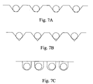
- FIG. 7A to 7C show, in cross-section, three different exemplary structures for wells in a substrate.
- FIG. 8 shows the efficiency of the layer by layer method in holding beads in wells.
- FIG. 8A depicts a plan view of an array of wells;
- FIG. 8B depicts an image of a similar well array as in FIG. 8A after bead assembly and washing and no other treatment;
- FIG. 8C depicts an image of a well array after bead assembly and washing for a chip coated with five polyelectrolyte bilayers;
- FIG. 8D shows the average approximate relative dimensions of a well and a bead as appearing in FIGS. 8A to 8C .
- FIG. 8E is a plan view of a bead in a well.
- FIG. 9A depicts, in plan view, a design of a hole (or trap) for beads in a substrate, which is a “squeezed” hexagon, in which the space between two opposing sides is less than the bead diameter.
- FIG. 9B depicts a design of a hole (or trap) for beads in a substrate, which is an asymmetric hexagon, where two opposing sides have a narrower space between them at one end than at the other, and are designed so that at the narrower edge, the space between the sides is less than the bead diameter.
- FIG. 1 an exemplary set of depressions (holes) in a substrate are depicted, which are suitable for insertion of beads which display biomolecules. Assay analytes and reagents can be added over the surface of the substrate and will make contact with the beads and the biomolecules displayed thereon.
- the holes narrow at the bottom to assist in holding the beads at the bottom of the holes.
- FIG. 7B the holes are cone-shaped to wedge in the beads.
- FIG. 7C the holes, in cross-section, are U shaped, and the beads can reside on either side of the hole.
- FIGS. 9A and 9B depict two different designs for holes, which have areas which are narrower than the bead diameters. The beads are squeezed into the holes, and held in place by the resulting expansion force.
- the beads were assembled on the substrate using the following protocol.
- An example of a processing procedure for forming bead arrays is as follows. Two microliters of 1% microparticles (approximately 3.2 micrometers in diameter) in 100 microliters of phosphate-buffered saline (also known as PBS: 150 mM, NaCl; 100 mM, Sodium phosphate, pH 7.2) were used for assembling microparticle arrays on individual silicon chips (1.75 ⁇ 1.75 mm) with microwells on each chip. The following procedures were used:
- the occupancy of the traps was checked by fluorescence microscopy. See FIG. 4A .
- a 2 ⁇ l droplet of the nanoparticle suspension was used for immobilization, by placing it on the substrate (having dimensions of 1.75 mm ⁇ 1.75 mm) and incubating at 30° C. and 30% relative humidity for 30 minutes. The selected incubation conditions avoided complete evaporation, which leads to the formation of an undesirable dry sintered film. After the incubation was over, the excess nanoparticle suspension was aspirated off and the surface of the chip was cleaned by thorough scrubbing and washing. The occupancy of the traps was checked again using fluorescence microscopy. The results are shown in FIGS. 4B to 4D .
- the bead assembly was carried out as described in Example1 using a 1% nanoparticle solution.
- the polymer blocking solution used for this study was 1% (w/v) PEG 20,000 dissolved in 10 mM Tris with 3% (v/v) glycerol.
- 15 ⁇ l of the polymer solution was added to each chip, which were stored in a humid chamber at 4° C. overnight.
- the excess polymer solution was removed from the chip surface and the chip was washed with de-ionized water.
- a hybridization assay was performed using a 90-nt Cy5 labeled polynucleotide target.
- Two microliters of a 10 ⁇ M solution of a synthetic target (5′-Cy5 dye- coupled to the oligo:TCAGTTTTCCTGGATTATGCCTGGCACCATTAAAGAAAATATCA TCTTTGGTGTTTCCTATGATGAATATAGATACAGAAGCGTCATCAA-3′ (SEQ ID NO. 1)) in de-ionized water was diluted with 18 ⁇ l of 1 ⁇ TMAC (4.5 M tetramethyl ammonium chloride, 75 mM Tris pH 8.0, 3 mM EDTA, 0.15% SDS) to a final volume of 20 ⁇ l.
- 1 ⁇ TMAC 4.5 M tetramethyl ammonium chloride, 75 mM Tris pH 8.0, 3 mM EDTA, 0.15% SDS
- the first microparticle type was functionalized with a matched probe sequence (SEQ ID NO.2) 5′-Amino/(TEGspacer)/CCAAAGATGATATTTTC/-3′ (“TEG” is triethylene glycol).
- the second microparticle type was functionalized with a mismatched probe sequence (SEQ ID NO. 3): Amino/(TEGspacer)/ATAACCAGGAGGAGTTCG/-3′). Twenty microliters of the synthetic target was added to the substrate surface and the substrate was placed in a 55° C. heater for 20 minutes. The substrate was then removed from the heater and the target solution was aspirated.
- the substrate was washed three times with 1 ⁇ TMAC at room temperature. Following this, 10 ⁇ l of 1 ⁇ TMAC was placed on the substrate surface, it was covered with a glass cover-slip and the fluorescence intensity of the array was recorded using fluorescence microscopy.
- control assays were done with chips without any added nanoparticle or polymer. In the unoccupied traps in the control assay, there is some non-specific binding of target in the traps. The results are shown in Table 2 and 3, where CV is the coefficient of variation.
- a negatively charged chip (a silicon substrate coated with a layer of silicon dioxide) was immersed in a cationic polyelectrolyte solution (a 1% w/v solution of polyallylamine hydrochloride, having Mol. Wt. 15,000, made by Aldrich Chemicals, Milwaukee, Wis., in 1M calcium chloride) for 2 minutes.
- a cationic polyelectrolyte solution a 1% w/v solution of polyallylamine hydrochloride, having Mol. Wt. 15,000, made by Aldrich Chemicals, Milwaukee, Wis., in 1M calcium chloride
- FIG. 5( a ) shows an array of traps coated with ten bilayers.
- DNA hybridization assays were carried out as described in Example 2. Two microliter of a 10 ⁇ M solution of a synthetic target (5′-Cy5 labeled TCAGTTTTCCTGGATTATGCCTGGCACCATTAAAGAAAATATCATCTTTGGTGTT TCCTATGATGAATATAGATACAGAAGCGTCATCAA-3′ (SEQ ID NO. 4)) in de-inonized water was diluted with 98 ⁇ l of 1 ⁇ TMAC (4.5 M tetramethyl ammonium chloride, 75 mM Tris pH 8.0, 3 mM EDTA, 0.15% SDS) to a final volume of 20 ⁇ l.
- 1 ⁇ TMAC 4.5 M tetramethyl ammonium chloride, 75 mM Tris pH 8.0, 3 mM EDTA, 0.15% SDS
- the first microparticle type was functionalized with a matched probe sequence 5′-Amino/(TEGspacer)/CCAAAGATGATATTTTC/-3′ (SEQ ID NO. 5).
- the second microparticle type was functionalized with a mismatched probe sequence Amino/(TEGspacer)/ATAACCAGGAGGAGTTCG/-3′ (SEQ ID NO. 6). Twenty microliters of the synthetic target was added to the substrate surface and the substrate was placed in a 55° C. oven for 20 minutes. The substrate was then removed from the oven the target solution was aspirated.
- the substrate was washed three times with 1 ⁇ TMAC at room temperature. Following this, 10 ⁇ l of 1 ⁇ TMAC was placed on the substrate surface, covered with a glass cover-slip and the fluorescence intensity of the array was recorded. The results are shown in FIG. 6 .
- the matched or the specific signal was unaltered but the non-specific signal was increased two fold, most likely because of non-specific binding to the coated substrate.
- Polyelectrolyte bilayer coated chips were fabricated as described in Example 5, but after the last exposure to Ludox solution, two additional bilayers were added, using Polyallylamine solution and a solution of 1% (w/v) Polyacrylic acid, sodium salt (Mol. Wt. 8,000, Aldrich Chemicals, Milwaukee, Wis.) in 1M calcium chloride. After the final polyacrylic acid deposition the chip was washed thoroughly with de-ionized ultra-filtered water and incubated at 120° C. for 2 hours. Beads were assembled on these coated chips as described before and hybridization assay was carried out as described in Example 5.
- Example 5 In some of the assays, in addition to the two types in Example 5, a third type of functionalized bead with a mismatched probe sequence Amino/(TEGspacer)/CCCCCCCCCC/-3 (SEQ ID NO. 7), was also used.
Landscapes
- Chemical & Material Sciences (AREA)
- Organic Chemistry (AREA)
- Chemical Kinetics & Catalysis (AREA)
- Medicinal Chemistry (AREA)
- Health & Medical Sciences (AREA)
- Life Sciences & Earth Sciences (AREA)
- Biochemistry (AREA)
- General Chemical & Material Sciences (AREA)
- Molecular Biology (AREA)
- Structural Engineering (AREA)
- Engineering & Computer Science (AREA)
- Apparatus Associated With Microorganisms And Enzymes (AREA)
- Measuring Or Testing Involving Enzymes Or Micro-Organisms (AREA)
Abstract
Description
where K denotes an elastic constant, W ˜√{square root over (γ1γ2)}, denotes the work of adhesion (where γ1 and γ2 are the surface energies of the two surfaces in contact) and R denotes the radius of curvature. In the absence of any applied load (P), the equilibrium contact radius is:
The theory also predicts an adhesive contact force (Fadh):
A large area of contact enhances adhesion, however it alone is not sufficient. For example, a wetting liquid achieves an excellent contact, but does not generate significant adhering force, because it does not resist shear deformation.
α=√{square root over (2Rσ roughness)}
where σroughness is the root mean square of the surface asperities and R the bulk radius of curvature of the system (radius of the sphere for a sphere and flat system). A recent study by Quon et al. (Quon, R. A., Knarr, R. F., and Vanderlick, T. K. Measurement of the Deformation and Adhesion of Rough Solids in Contact. J. Phys. Chem. B 1999, 103, 5320-5327) concluded that systems that are in initial contact over an area with a radius greater than that predicted above are strongly adherent and ones with a smaller radius of contact are either weakly adherent or non-adherent. Thus, for rough solids, the adhesion improves with increasing initial loads. Under the influence of an increased initial load, asperities deform, permitting the surfaces to approach more closely and thereby permitting van der Waals attractions to contribute to adhesion.
-
- Microparticles from PBS were collected in an 1.5 ml centrifuge tube by centrifugation (14,000 g, 1 minute). Other collection means may be used.
- The supernatant was discarded by aspiration using a transfer pipet.
- The particles were re-suspended in 5 microliters of 3% glycerol in 10 mM Tris pH 7.5.
- The particles were collected from the glycerol solution by centrifugation. Other collection means may be used.
- The glycerol solution was aspirated from the particle pellets.
- The pellets were re-suspended in 2 microliter of the 3% glycerol, 10 mM Tris, pH 7.5.
- Silicon chips pre-bonded to a glass microscope slide were taken.
- A 0.25 microliter volume of the particle suspension was pipetted onto each of the chips in the area including the microwells.
- The assembled chips were left in an enclosed chamber for a short period of time (e.g. 30 min) to allow the beads to settle down ands excess water to evaporate.
- After the incubation the droplet became more of a viscous slurry.
- A cotton applicator was washed with water from a wash bottle.
- The wet cotton applicator was dried using absorbant tissue paper to remove excess water. To assemble microparticle arrays, the bead slurry was gently stirred with the tip of the wet cotton applicator in a circular motion several times. The loose fibers of the cotton ball ferried the beads into the microwells on the surface.
- Following step above, the slide was centrifuged to promote the settling of the beads in the ( microwells) on the chip. The following materials and settings were used:
- Centrifuge: Sorvall centrifuge model RT6000B
- Rotor: Sorvall swing bucket model H1000B
- Speed: 2000 RPM
- Time: 5 min
- The particle occupancy of the microwells was examined by using a fluorescent microscope. If the occupancy is not satisfactory, the step above can be repeated.
- Excess particles were gently wiped away from the chip by using the cotton applicator. To avoid excess water on the surface, the cotton applicator was not pressed against the chip.
- The chip was dried by blowing on the surface of the chip with compressed nitrogen.
- The assembled microparticle prepared by this method can be used for assays or stored in solution at 4° C. for later use.
| TABLE 2 |
| Results on polymer blocked nanoparticle immobilized chips |
| Matched | Mismatched | Unoccupied | |||
| Chip# | probe signal | probe signal | Ratio | traps | |
| 1 | 9603 | 783 | 12.26 | 558 | |
| CV 8% | CV 36 | CV | 20% | ||
| 2 | 11,902 | 695 | 17.12 | 545 | |
| |
CV 24% | CV 21% | |||
| 3 | 10,264 | 731 | 14.04 | 539 | |
| | CV | 30% | CV 18% | ||
| 4 | 10,631 | 1058 | 10.04 | — | |
| CV 11% | CV 33% | ||||
| TABLE 3 |
| Results on uncoated (control) chips |
| Chip | Matched | Mismatched | Unoccupied | |
| # | probe signal | probe signal | Ratio | traps |
| 1 | 12,958 | 790 | 16.4 | 613 |
| CV 7% | CV 31% | CV 39% | ||
| 2 | 12,343 | 841 | 14.67 | 745 |
| | CV 28% | CV 29% | ||
The immobilization protocol along with the polymer blocking step preserved the signal for the matched probes (˜10% drop in the specific assay signal), and decreased the non-specific signal from the chip surface (˜20%), while the signal from binding of the mismatched probes was essentially unaffected.
| TABLE 4 |
| Dimensions and size mismatch for various trap sizes |
| Chip# | Trap size (microns) | Mismatch (nm) |
| 1 | 3.5 | 300 |
| 2 | 3.4 | 200 |
| 3 | 3.3 | 100 |
The bilayer coating was carried out as described above in Example 3. Table 5 shows the results for the various trap sizes. For a larger mismatch between the bead and the trap size, more bilayer-coatings are needed for immobilization.
| TABLE 5 |
| Minimum number of bilayers needed for immobilization |
| Chip |
| Trap size | Expected layer | # of bilayers |
| Chip # | (microns) | thickness (nm) | 1 | 2 | 3 | 4 | 5 |
| 1 | 3.5 | 200 |
|
|
|||
| 2 | 3.4 | 120 |
|
|
|
||
| 3 | 3.3 | 80 |
|
|
|
|
|
| *the cells with grey color indicate where the immobilization was effective. | |||||||
| TABLE 6 |
| with % CV |
| Non-specific | ||||
| Specific | Non-specific | signal_2 | Unoccupied | |
| Chip# | signal | signal_1 | (another probe) | traps |
| Chip_1 | 5555 (10%) | 186 (26%) | 200 (25%) | 184 (24%) |
| Chip_2 | 5553 (14%) | 224 (30%) | 237 (30%) | 186 (37%) |
| Chip_3 | 5593 (14%) | 222 (34%) | 237 (34%) | 174 (31%) |
| Chip_4 | 5780 (14%) | 247 (22%) | 263 (22%) | 239 (24%) |
| Chip_5 | 5800 (10%) | 214 (22%) | — | 214 (27%) |
| Chip_6 | 5542 (10%) | 251 (23%) | — | 207 (24%) |
| Chip_7 | 5573 (10%) | 270 (22%) | — | 240 (16%) |
| Chip_8 | 5398 (10%) | 280 (24%) | — | 210 (26%) |
| Control_1 | 5600 (10%) | 210 (20%) | — | 186 (30%) |
| Control_2 | 5800 (10%) | 240 (24%) | — | 216 (25%) |
It should be understood that the terms, expressions, examples and embodiments depicted above are exemplary only and not limiting, and that the scope of the invention is defined only in the claims which follow, and includes all equivalents of the subject matter of the claims.
Claims (16)
Priority Applications (1)
| Application Number | Priority Date | Filing Date | Title |
|---|---|---|---|
| US10/868,451 US7452565B2 (en) | 2003-06-12 | 2004-06-13 | Immobilization of bead-displayed ligands on substrate surfaces |
Applications Claiming Priority (2)
| Application Number | Priority Date | Filing Date | Title |
|---|---|---|---|
| US47801103P | 2003-06-12 | 2003-06-12 | |
| US10/868,451 US7452565B2 (en) | 2003-06-12 | 2004-06-13 | Immobilization of bead-displayed ligands on substrate surfaces |
Publications (2)
| Publication Number | Publication Date |
|---|---|
| US20050112277A1 US20050112277A1 (en) | 2005-05-26 |
| US7452565B2 true US7452565B2 (en) | 2008-11-18 |
Family
ID=33551798
Family Applications (1)
| Application Number | Title | Priority Date | Filing Date |
|---|---|---|---|
| US10/868,451 Active 2026-12-25 US7452565B2 (en) | 2003-06-12 | 2004-06-13 | Immobilization of bead-displayed ligands on substrate surfaces |
Country Status (2)
| Country | Link |
|---|---|
| US (1) | US7452565B2 (en) |
| WO (1) | WO2004111260A2 (en) |
Cited By (2)
| Publication number | Priority date | Publication date | Assignee | Title |
|---|---|---|---|---|
| US20080182287A1 (en) * | 2004-07-02 | 2008-07-31 | Biostatus Limited | Gel Formulations and Uses Thereof |
| US9447458B2 (en) | 2011-11-16 | 2016-09-20 | Canon U.S. Life Sciences, Inc. | Detection of neighboring variants |
Families Citing this family (17)
| Publication number | Priority date | Publication date | Assignee | Title |
|---|---|---|---|---|
| GB2441784A (en) * | 2006-09-13 | 2008-03-19 | Rtc North Ltd | Device for obtaining and analysing a biological fluid |
| CA2580589C (en) * | 2006-12-19 | 2016-08-09 | Fio Corporation | Microfluidic detection system |
| CA2682826C (en) | 2007-04-02 | 2013-08-13 | Fio Corporation | System and method of deconvolving multiplexed fluorescence spectral signals generated by quantum dot optical coding technology |
| CN101821322B (en) | 2007-06-22 | 2012-12-05 | Fio公司 | Systems and methods for manufacturing quantum dot-doped polymer microbeads |
| US8551786B2 (en) * | 2007-07-09 | 2013-10-08 | Fio Corporation | Systems and methods for enhancing fluorescent detection of target molecules in a test sample |
| US20100257027A1 (en) * | 2007-07-23 | 2010-10-07 | Fio Corporation | Method and system for collating, storing, analyzing and enabling access to collected and analyzed data associated with biological and environmental test subjects |
| WO2009046540A1 (en) * | 2007-10-12 | 2009-04-16 | Fio Corporation | Flow focusing method and system for forming concentrated volumes of microbeads, and microbeads formed further thereto |
| BRPI0915514A2 (en) | 2008-06-25 | 2016-01-26 | Fio Corp | biohazard warning infrastructure system and method, biohazard warning device and a method for alerting a user |
| CA2735273A1 (en) | 2008-08-29 | 2010-03-04 | Fio Corporation | A single-use handheld diagnostic test device, and an associated system and method for testing biological and environmental test samples |
| RU2578023C2 (en) | 2009-01-13 | 2016-03-20 | Эф-Ай-Оу Корпорейшн | Portable diagnostic unit and method for using it with electronic device and diagnostic cartridge in instant diagnostic tests |
| US9523701B2 (en) | 2009-07-29 | 2016-12-20 | Dynex Technologies, Inc. | Sample plate systems and methods |
| GB0913258D0 (en) * | 2009-07-29 | 2009-09-02 | Dynex Technologies Inc | Reagent dispenser |
| CN103140292B (en) * | 2010-07-29 | 2015-01-21 | 丹耐克斯技术有限公司 | Sample plate |
| GB2524541A (en) * | 2014-03-26 | 2015-09-30 | Ibm | Microfluidic chip with conic bead trapping cavities and fabrication thereof |
| WO2018175500A1 (en) * | 2017-03-21 | 2018-09-27 | Hexanomics, Inc. | Sealed microwell assay |
| CA3067036A1 (en) * | 2017-06-12 | 2018-12-20 | Essenlix Corporation | Homogeneous assay |
| EP3743724A4 (en) | 2018-01-25 | 2021-11-10 | Essenlix Corporation | Assaying cells and non-cell analytes in a sample in parallel |
Citations (7)
| Publication number | Priority date | Publication date | Assignee | Title |
|---|---|---|---|---|
| EP0472990A2 (en) | 1990-08-25 | 1992-03-04 | Bayer Ag | Mono or multilayer deposits on a substrat and process for making them |
| US20030082487A1 (en) | 2001-10-29 | 2003-05-01 | Robert Burgess | Three dimensional printing using photo-activated building materials |
| US20030082587A1 (en) * | 2001-12-28 | 2003-05-01 | Michael Seul | Arrays of microparticles and methods of preparation thereof |
| US20030129296A1 (en) * | 2001-07-17 | 2003-07-10 | David Kelso | Film-immobilized capture particles |
| US20030138842A1 (en) * | 2001-06-21 | 2003-07-24 | Michael Seul | Directed assembly of functional heterostructures |
| US20040132122A1 (en) * | 2000-06-21 | 2004-07-08 | Sukanta Banerjee | Multianalyte molecular analysis using application-specific random particle arrays |
| US20050048570A1 (en) * | 2001-12-28 | 2005-03-03 | Fraunhofer-Gesellschaft Zur Forderung Der Angewandten | Structured-functional bonding matrices for biomolecules |
-
2004
- 2004-06-13 US US10/868,451 patent/US7452565B2/en active Active
- 2004-06-13 WO PCT/US2004/018901 patent/WO2004111260A2/en unknown
Patent Citations (8)
| Publication number | Priority date | Publication date | Assignee | Title |
|---|---|---|---|---|
| EP0472990A2 (en) | 1990-08-25 | 1992-03-04 | Bayer Ag | Mono or multilayer deposits on a substrat and process for making them |
| US5208111A (en) | 1990-08-25 | 1993-05-04 | Bayer Aktiengesellschaft | One- or multi-layered layer elements applied to supports and their production |
| US20040132122A1 (en) * | 2000-06-21 | 2004-07-08 | Sukanta Banerjee | Multianalyte molecular analysis using application-specific random particle arrays |
| US20030138842A1 (en) * | 2001-06-21 | 2003-07-24 | Michael Seul | Directed assembly of functional heterostructures |
| US20030129296A1 (en) * | 2001-07-17 | 2003-07-10 | David Kelso | Film-immobilized capture particles |
| US20030082487A1 (en) | 2001-10-29 | 2003-05-01 | Robert Burgess | Three dimensional printing using photo-activated building materials |
| US20030082587A1 (en) * | 2001-12-28 | 2003-05-01 | Michael Seul | Arrays of microparticles and methods of preparation thereof |
| US20050048570A1 (en) * | 2001-12-28 | 2005-03-03 | Fraunhofer-Gesellschaft Zur Forderung Der Angewandten | Structured-functional bonding matrices for biomolecules |
Non-Patent Citations (22)
| Title |
|---|
| Brown, Patrick O., et al. "Exploring the new world of the genome with DNA microarrays". Nature Genetics Supplement, Jan. 1999: 33-37. vol. 21. |
| Cheng, J., et al. "Preparation and hybridization analysis of DNA/RNA from E. coli on microfabricated bioelectronic chips." Nature Biotechnology, Jun. 1998: 541-546, vol. 16. |
| Cheung, Vivian G., et al. "Making and reading microarrays." Nature Genetics Supplement, Jan. 1999: 15-19. vol. 21. |
| Crisp, M. Todd, et al. "Preparation of Nanoparicle Coatings on Surfaces of Complex Geometry." Nano Letters, 2003: 173-177. vol. 3, No. 2. |
| Decher, G. "Fuzzy Nanoassemblies: Toward Layered Polymeric Multicomposites." Science, Aug. 29, 1997: 1232-1237. vol. 277. |
| Duggan, David J., et al. "Expression profiling using cDNA microarrys." Nature Genetics Supplement, Jan. 1999: 10-14. vol. 21. |
| Fodor, Stephen P.A., et al. "Light-Directed, Spatially Addressable Parallel Chemical Synthesis". Science, Feb. 15, 1991: 767-772, vol. 251. |
| Giorgi, Rodorico, et al. "Nanotechnologies for Conservation of Cultural Heritage: Paper and Canvas Deacidification." Langmuir, 2002: 8198-8203. vol. 18. |
| Greenwood, J.A., et al. "The Elastic Contact of Rough Spheres". Journal of Applied Mechanics, Mar. 1967: 153-159. |
| Hiller, Jeri'ann, et al. "Reversibly erasable nanoporous anti-reflection coatings from polyelectrolyte multilayers." Nature Materials, Sep. 2002: 59-63. vol. 1. |
| Iler, R.K. "Multilayers of Colloidal Particles." Journal of Colloid and Interface Science, 1966: 569-594. vol. 21. |
| Johnson, K.L., et al. "Surface energy and the contact of elastic solids." Proc. R. Soc. Lond. A., 1971: 301-313. vol. 324. |
| Kotov, Nicholas A., et al. "Layer-by-Layer Self-Assembly of Polyelectrolyte-Semiconductor Nanoparticle Composite Films". J. Phys. Chem., 1995: 13065-13069. vol. 99. |
| Lipshutz, Robert J., et al. "High density synthetic oligonucleotide arrays." Nature Genetics Supplement, Jan. 1999: 20-24. vol. 21. |
| Lvov, Yuri, et al. "Alternate Assembly of Ordered Multilayers of SiO<SUB>2 </SUB>and Other Nanopaticles and Polyions." Langmuir, 1997: 6196-6203. vol. 13. |
| Maskos, Uwe, et al. "Oligonucleotide hybridizations on glass supports: a novel linker for oligonucleotide synthesis and hybridization properties of oligonucleotides synthesise in situ." Nucleic Acids Research, 1992: 1679-1684. vol. 20, No. 7. |
| Quon, R. A., et al. "Measurement of the Deformation and Adhesion of Rough Solids in Contact". J. Phys. Chem. B, 1999: 5320-5327, vol. 103. |
| Ramsay, Graham. "DNA Chips: State-of-the-art". Nature BioTechnology, Jan. 1998: 40-44. vol. 16. |
| Sennerfors, Therese, et al. "Adsorption of Polyelectrode-Nanoparticle Systems on Silica: Influence of Ionic Strength". Journal of Colloid and Interface Science, 2002: 222-226. vol. 254. |
| Serizawa, Takeshi, et al. "Electrostatic Adsorption of Polystyrene Nanospheres onto the Surface of an Ultrathin Polymer Film Prepared by Using an Alternate Adsorption Technique". Langmuir, 1998: 4088-4094. vol. 14. |
| Smay, James E., et al. "Colloidal Inks for Directed Assembly of 3-D Periodic Structures." Langmuir, 2002: 5429-5437. vol. 18. |
| Vasiliskov, A.V., et al. "Fabrication of Mircoarray of Gel-Immobilized Compounds on a Chip by Copolymerization". BioTechniques, Sep. 1999: 592-606. vol. 27. |
Cited By (3)
| Publication number | Priority date | Publication date | Assignee | Title |
|---|---|---|---|---|
| US20080182287A1 (en) * | 2004-07-02 | 2008-07-31 | Biostatus Limited | Gel Formulations and Uses Thereof |
| US7723085B2 (en) * | 2004-07-02 | 2010-05-25 | Biostatus Limited | Analyzing cells immobilized in block copolymers |
| US9447458B2 (en) | 2011-11-16 | 2016-09-20 | Canon U.S. Life Sciences, Inc. | Detection of neighboring variants |
Also Published As
| Publication number | Publication date |
|---|---|
| WO2004111260A2 (en) | 2004-12-23 |
| WO2004111260A3 (en) | 2005-11-24 |
| US20050112277A1 (en) | 2005-05-26 |
Similar Documents
| Publication | Publication Date | Title |
|---|---|---|
| US7452565B2 (en) | Immobilization of bead-displayed ligands on substrate surfaces | |
| CA2471693C (en) | Arrays of microparticles and methods of preparation thereof | |
| KR20110036002A (en) | Microfluidic selection of library elements | |
| EP1682866A2 (en) | Gel-shell beads with adsorbed or bound biomolecules | |
| JP6751970B2 (en) | Flow systems and methods for digital counting | |
| WO2001019517A1 (en) | Analytical test device with substrate having oriented through going channels and improved methods and apparatus for using same | |
| EP1169649A2 (en) | Microarrays of polypeptides | |
| US20040121339A1 (en) | Special film-coated substrate for bio-microarray fabrication and use thereof | |
| EP1311853B1 (en) | Combination of microporous membrane and solid support for microdiagnostics | |
| JP2006523312A (en) | Universal reading for target identification using biological microassays | |
| JP6925051B2 (en) | Improved method for digital counting | |
| JP2006519384A5 (en) | ||
| JP4197279B2 (en) | Biologically-derived substance detection substrate and manufacturing method thereof | |
| JP2006519384A (en) | Highly integrated analysis chip with extremely small height reactor and its application | |
| US7824927B2 (en) | Analyte detection using an active assay | |
| US20120076694A1 (en) | Analyte Detection Using an Active Assay | |
| US20040009584A1 (en) | Method for manufacturing microarrays based on the immobilization of porous substrates on thermally modifiable surfaces | |
| Cameron | Banerjee et a1. | |
| US20060228813A1 (en) | Method for immobilizing biomolecules on metal oxide substrates | |
| TW200540276A (en) | Immobilization of bead-displayed ligands on substrate surfaces | |
| EP3505934A1 (en) | A sensor body for binding and/or enriching and/or detecting an analyte in a sample | |
| JP2005520568A5 (en) | ||
| KR102047061B1 (en) | Double coded microdisk and multiplexed bioassay using it | |
| Atsuta et al. | Protein patterning with PDMS sieve | |
| JP2011072210A (en) | Sensor chip and method for using the same |
Legal Events
| Date | Code | Title | Description |
|---|---|---|---|
| AS | Assignment |
Owner name: BIOARRAY SOLUTIONS LTD., NEW JERSEY Free format text: ASSIGNMENT OF ASSIGNORS INTEREST;ASSIGNOR:BANERJEE, SUKANTA;REEL/FRAME:020498/0860 Effective date: 20030916 |
|
| STCF | Information on status: patent grant |
Free format text: PATENTED CASE |
|
| AS | Assignment |
Owner name: CITIBANK, N.A., AS ADMINISTRATIVE AGENT, DELAWARE Free format text: PATENT SECURITY AGREEMENT;ASSIGNORS:IMMUCOR, INC.;BIOARRAY SOLUTIONS LTD.;REEL/FRAME:026778/0640 Effective date: 20110819 |
|
| FPAY | Fee payment |
Year of fee payment: 4 |
|
| FPAY | Fee payment |
Year of fee payment: 8 |
|
| MAFP | Maintenance fee payment |
Free format text: PAYMENT OF MAINTENANCE FEE, 12TH YEAR, LARGE ENTITY (ORIGINAL EVENT CODE: M1553); ENTITY STATUS OF PATENT OWNER: LARGE ENTITY Year of fee payment: 12 |
|
| AS | Assignment |
Owner name: ALTER DOMUS (US) LLC, AS ADMINISTRATIVE AGENT, ILLINOIS Free format text: SECURITY INTEREST;ASSIGNORS:IMMUCOR, INC.;BIOARRAY SOLUTIONS LTD.;SIRONA GENOMICS, INC.;AND OTHERS;REEL/FRAME:053119/0152 Effective date: 20200702 Owner name: HPS INVESTMENT PARTNERS, LLC, AS ADMINISTRATIVE AGENT, NEW YORK Free format text: SECURITY INTEREST;ASSIGNORS:IMMUCOR, INC.;BIOARRAY SOLUTIONS LTD.;SIRONA GENOMICS, INC.;AND OTHERS;REEL/FRAME:053119/0135 Effective date: 20200702 Owner name: IMMUCOR, INC., GEORGIA Free format text: RELEASE OF PATENT SECURITY INTERESTS;ASSIGNOR:CITIBANK, N.A.;REEL/FRAME:053121/0935 Effective date: 20200702 Owner name: IMMUCOR GTI DIAGNOSTICS, INC., GEORGIA Free format text: RELEASE OF PATENT SECURITY INTERESTS;ASSIGNOR:CITIBANK, N.A.;REEL/FRAME:053121/0935 Effective date: 20200702 Owner name: BIOARRAY SOLUTIONS LTD., NEW JERSEY Free format text: RELEASE OF PATENT SECURITY INTERESTS;ASSIGNOR:CITIBANK, N.A.;REEL/FRAME:053121/0935 Effective date: 20200702 Owner name: SIRONA GENONICS, INC., MASSACHUSETTS Free format text: RELEASE OF PATENT SECURITY INTERESTS;ASSIGNOR:CITIBANK, N.A.;REEL/FRAME:053121/0935 Effective date: 20200702 |
|
| AS | Assignment |
Owner name: IMMUCOR GTI DIAGNOSTICS, INC., GEORGIA Free format text: RELEASE BY SECURED PARTY;ASSIGNOR:ALTER DOMUS (US) LLC, AS COLLATERAL AGENT;REEL/FRAME:063090/0111 Effective date: 20230314 Owner name: SIRONA GENOMICS, INC., GEORGIA Free format text: RELEASE BY SECURED PARTY;ASSIGNOR:ALTER DOMUS (US) LLC, AS COLLATERAL AGENT;REEL/FRAME:063090/0111 Effective date: 20230314 Owner name: BIOARRAY SOLUTIONS LTD., GEORGIA Free format text: RELEASE BY SECURED PARTY;ASSIGNOR:ALTER DOMUS (US) LLC, AS COLLATERAL AGENT;REEL/FRAME:063090/0111 Effective date: 20230314 Owner name: IMMUCOR, INC., GEORGIA Free format text: RELEASE BY SECURED PARTY;ASSIGNOR:ALTER DOMUS (US) LLC, AS COLLATERAL AGENT;REEL/FRAME:063090/0111 Effective date: 20230314 Owner name: IMMUCOR GTI DIAGNOSTICS, INC., GEORGIA Free format text: RELEASE BY SECURED PARTY;ASSIGNOR:HPS INVESTMENT PARTNERS, LLC, AS ADMINISTRATIVE AGENT;REEL/FRAME:063090/0033 Effective date: 20230314 Owner name: SIRONA GENOMICS, INC., GEORGIA Free format text: RELEASE BY SECURED PARTY;ASSIGNOR:HPS INVESTMENT PARTNERS, LLC, AS ADMINISTRATIVE AGENT;REEL/FRAME:063090/0033 Effective date: 20230314 Owner name: BIOARRAY SOLUTIONS LTD., GEORGIA Free format text: RELEASE BY SECURED PARTY;ASSIGNOR:HPS INVESTMENT PARTNERS, LLC, AS ADMINISTRATIVE AGENT;REEL/FRAME:063090/0033 Effective date: 20230314 Owner name: IMMUCOR, INC., GEORGIA Free format text: RELEASE BY SECURED PARTY;ASSIGNOR:HPS INVESTMENT PARTNERS, LLC, AS ADMINISTRATIVE AGENT;REEL/FRAME:063090/0033 Effective date: 20230314 |