US7477471B1 - Disk drive employing offset compensation for velocity control of a voice coil motor - Google Patents
Disk drive employing offset compensation for velocity control of a voice coil motor Download PDFInfo
- Publication number
- US7477471B1 US7477471B1 US11/788,507 US78850707A US7477471B1 US 7477471 B1 US7477471 B1 US 7477471B1 US 78850707 A US78850707 A US 78850707A US 7477471 B1 US7477471 B1 US 7477471B1
- Authority
- US
- United States
- Prior art keywords
- voltage
- voice coil
- control
- recited
- vcm
- Prior art date
- Legal status (The legal status is an assumption and is not a legal conclusion. Google has not performed a legal analysis and makes no representation as to the accuracy of the status listed.)
- Expired - Fee Related, expires
Links
Images


Classifications
-
- G—PHYSICS
- G11—INFORMATION STORAGE
- G11B—INFORMATION STORAGE BASED ON RELATIVE MOVEMENT BETWEEN RECORD CARRIER AND TRANSDUCER
- G11B5/00—Recording by magnetisation or demagnetisation of a record carrier; Reproducing by magnetic means; Record carriers therefor
- G11B5/48—Disposition or mounting of heads or head supports relative to record carriers ; arrangements of heads, e.g. for scanning the record carrier to increase the relative speed
- G11B5/58—Disposition or mounting of heads or head supports relative to record carriers ; arrangements of heads, e.g. for scanning the record carrier to increase the relative speed with provision for moving the head for the purpose of maintaining alignment of the head relative to the record carrier during transducing operation, e.g. to compensate for surface irregularities of the latter or for track following
- G11B5/596—Disposition or mounting of heads or head supports relative to record carriers ; arrangements of heads, e.g. for scanning the record carrier to increase the relative speed with provision for moving the head for the purpose of maintaining alignment of the head relative to the record carrier during transducing operation, e.g. to compensate for surface irregularities of the latter or for track following for track following on disks
- G11B5/59627—Aligning for runout, eccentricity or offset compensation
Definitions
- the present invention relates to disk drives for computer systems.
- the present invention relates to a disk drive employing offset compensation for velocity control of a voice coil motor.
- Disk drives comprise a disk and a head connected to a distal end of an actuator arm which is rotated about a pivot by a voice coil motor (VCM) to position the head radially over the disk.
- VCM voice coil motor
- the disk comprises a plurality of radially spaced, concentric tracks for recording user data sectors and embedded servo sectors.
- the embedded servo sectors comprise head positioning information (e.g., a track address) which is read by the head and processed by a servo control system to control the velocity of the actuator arm as it seeks from track to track.
- the servo control system does not have access to the embedded servo sectors yet it is still desirable to control the velocity of the actuator arm. For example, in disk drives employing ramp loading/unloading, it is desirable to control the velocity of the actuator arm so that the head is not damaged as it travels off the ramp onto the disk as well as off the disk onto the ramp. Another example is if the servo control system loses servo sector synchronization it is desirable to control the velocity of the actuator arm to facilitate re-synchronizing to the servo sectors.
- Prior art techniques for controlling the velocity of the actuator arm when servo sector information is unavailable include using a voltage loop with the detected back EMF voltage generated by the VCM as the feedback.
- the voltage across the voice coil (the voice coil voltage) comprises a component due to the inductance L of the VCM, a component due to the resistance R of the VCM, and a component due to the velocity of the VCM referred to as the back EMF voltage. If the component due to the resistance R is canceled from the voice coil voltage, at low frequencies Ldi/dt is small leaving the back EMF voltage due to the velocity of the VCM as the dominant component.
- Various analog components such as differential operational amplifiers (op-amps) are typically employed in the feedback loop, for example to detect the voice coil voltage and/or the current flowing through a sense resistor in series with the voice coil.
- the various analog components may have a non-zero input offset voltage that can distort the back EMF measurement.
- a known technique for determining the input offset voltage involves zeroing the input to the op amp that measures the voice coil voltage and adjusting the control voltage until the detected current flowing through the sense resistor is zero. The control voltage that generates the detected zero current is then used to adjust the control voltage during normal operation in order to compensate for the offset.
- this technique may not account for the offset voltage of the current sensing op-amp, and/or it may be obfuscated by quantization error and/or signal noise that may vary depending on the ambient temperature.
- An embodiment of the present invention comprises a disk drive comprising a disk, a head, a voice coil motor (VCM) comprising a voice coil operable to actuate the head radially over the disk, the voice coil comprising a first end and a second end.
- the disk drive further comprises a VCM control loop including a voltage detector operable to detect a back EMF voltage across the voice coil, a current detector operable to detect a current flowing through the voice coil, and a control voltage generator, responsive to a command input and the detected back EMF voltage, operable to generate a control voltage applied to the voice coil.
- Control circuitry within the disk drive (a) initializes the control voltage; (b) injects a transient into the VCM control loop and detects a corresponding current flowing through the voice coil; (c) adjusts the control voltage in response to a polarity of the detected current; (d) repeats elements (b) and (c) at least once; and (e) stores an offset value in response to the adjusted control voltage.
- control voltage generator is responsive to the stored offset value to generate the control voltage.
- control circuitry adjusts the control voltage relative to a delta value. In one embodiment, the control circuitry adjusts the delta value when the polarity of the detected current changes sign, and in one embodiment, the control circuitry decreases the delta value when the polarity of the detected current changes sign.
- the control circuitry injects the transient into the VCM control loop by injecting a transient into the detected back EMF voltage.
- the disk drive comprises an IR voltage detector, responsive to the detected current, operable to detect a resistive voltage due to a resistance of the voice coil, and a voltage compensator for adjusting the detected back EMF voltage in response to the detected resistive voltage, wherein the control circuitry injects the transient into the detected back EMF voltage by adjusting the IR voltage detector.
- the IR voltage detector comprises a variable resistor representing a resistance estimate of the voice coil, and the control circuitry injects the transient into the detected back EMF voltage by adjusting the variable resistor.
- the control circuitry injects the transient into the detected back EMF voltage by increasing a resistance of the variable resistor.
- control circuitry is further operable to tristate the voice coil for a tristate interval after detecting the current flowing through the voice coil.
- the current detector comprises a variable resistor
- the control circuitry injects the transient into the VCM control loop by adjusting the variable resistor.
- control circuitry injects the transient into the VCM control loop by adjusting a gain of an amplifier.
- Another embodiment of the present invention comprises a method of operating a voice coil motor (VCM) control loop in a disk drive, the disk drive comprising a disk, a head, a VCM comprising a voice coil operable to actuate the head radially over the disk, the voice coil comprising a first end and a second end.
- VCM voice coil motor
- FIG. 1A shows a disk drive according to an embodiment of the present invention comprising a VCM for actuating a head over the disk, a back EMF voltage detector, a current detector, and a control voltage generator, responsive to a command input and the detected back EMF voltage, operable to generate a control voltage applied to the voice coil.
- FIG. 1B is a flow diagram according to an embodiment of the present invention for calibrating an offset voltage for use in a velocity control of the VCM.
- FIG. 2 shows an embodiment of the present invention wherein the control voltage generator is responsive to the stored offset value to generate the control voltage applied to the VCM.
- FIG. 3 is a flow diagram according to an embodiment of the present invention wherein the control voltage applied to the VCM is adjusted by a delta which is decreased when the polarity of the detected current changes sign.
- FIG. 4 shows a disk drive according to an embodiment of the present invention wherein the back EMF voltage detector comprises an IR voltage detector operable to detect a resistive voltage representing a resistance of the VCM, and a voltage compensator for adjusting the detected back EMF voltage in response to the resistive voltage.
- the back EMF voltage detector comprises an IR voltage detector operable to detect a resistive voltage representing a resistance of the VCM, and a voltage compensator for adjusting the detected back EMF voltage in response to the resistive voltage.
- FIG. 5 is a flow diagram according to an embodiment of the present invention wherein a variable resistor of the IR voltage detector is adjusted to inject a transient into the detected back EMF voltage.
- FIG. 6 shows a disk drive according to an embodiment of the present invention wherein the VCM is tristated for a tristate period.
- FIG. 7 is flow diagram according to an embodiment of the present invention wherein the VCM is tristated for a tristate period after injecting the transient into the back EMF voltage and detecting the current.
- FIG. 8 is a circuit diagram according to an embodiment of the present invention including a plurality of op-amps for implementing the back EMF voltage detector, current detector, and IR voltage detector.
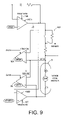
- FIG. 9 is a circuit diagram according to an embodiment of the present invention wherein the transient is injected into the detected back EMF voltage by adjusting a sense resistor, or by adjusting a gain of an op-amp.
- FIG. 1A shows a disk drive according to an embodiment of the present invention comprising a disk 2 , a head 4 , a voice coil motor (VCM) 6 comprising a voice coil 8 operable to actuate the head 4 radially over the disk 2 , the voice coil 8 comprising a first end and a second end.
- the disk drive further comprises a VCM control loop including a voltage detector 10 operable to detect a back EMF voltage 12 across the voice coil 8 , a current detector 14 operable to detect a current 16 flowing through the voice coil 8 , and a control voltage generator 18 , responsive to a command input 20 and the detected back EMF voltage 12 , operable to generate a control voltage 22 applied to the voice coil.
- Control circuitry 24 within the disk drive executes the flow diagram shown in FIG. 1B to calibrate an offset value for the circuitry shown in FIG. 1A according to an embodiment of the present invention, wherein at step 26 the control voltage is initialized to a suitable value (e.g., zero). At step 28 a transient is injected into the VCM control loop, and at step 30 a corresponding current flowing through the voice coil is detected.
- the control circuitry 24 may inject a transient into the VCM control loop at step 28 in any suitable manner, such as adjusting the voltage detector 10 , the current detector 14 , and/or the control voltage generator 18 .
- a polarity of the detected current is evaluated, wherein the control voltage is increased if the detected current is a first polarity at step 34 , or the control voltage is decreased if the detected current is a second polarity at step 36 .
- the flow diagram of FIG. 1B is repeated at least once starting at step 28 until a predetermined condition is satisfied at step 38 . For example, in one embodiment the flow diagram is repeated until the polarity of the detected current changes sign.
- an offset value is stored in response to the adjusted control voltage for use in offset compensation during normal operation. For example, in one embodiment the offset value is selected at step 40 as a value that will generate the adjusted control voltage value at the end of the calibration procedure.
- FIG. 2 shows a disk drive according to an embodiment of the present invention wherein the control voltage generator 18 comprises a register 42 for storing the command input 20 representing a target velocity of the VCM 6 , a register 44 for storing the offset value, and an adder 46 for combining the command input 20 , the offset value 44 , and the detected back EMF voltage 12 .
- the output of adder 46 is converted by a digital-to-analog converter (DAC) 48 into the control voltage 22 applied to the VCM 6 .
- DAC digital-to-analog converter
- the control circuitry 24 adjusts the control voltage 22 (at steps 34 and 36 of FIG. 1B ) by adjusting the command input 20 value stored in register 42 .
- the end of the calibration procedure at step 40 of FIG.
- control circuitry copies the command input 20 value stored in register 42 to the offset value register 44 .
- control circuitry 24 adjusts the control voltage 22 by adjusting the offset value stored in register 44 so that register 44 stores the correct offset value at the end of the calibration procedure.
- FIG. 3 shows a flow diagram implemented by the control circuitry 24 according to an embodiment of the present invention wherein at step 50 the control voltage is initialized to a suitable value (e.g., zero), and at step 52 a delta (A) is initialized to a suitable value (e.g., a maximum value).
- a transient is injected into the VCM control loop, and at step 56 a corresponding current flowing through the voice coil is detected. If at step 58 the polarity of the detected current changes sign (relative to the previous detected value), then at step 60 the delta is decreased.
- the control voltage is increased by the delta if the detected current has a first polarity at step 62 , or the control voltage is decreased by the delta at step 66 if the detected current has a second polarity.
- the flow diagram of FIG. 3 is repeated at least once starting at step 54 , and then at step 70 the offset value is stored in response to the adjusted control voltage. In one embodiment, the flow diagram of FIG. 3 is repeated until a suitable condition is detected, such as the delta falling below a predetermined threshold, or remaining at or below the threshold for a number of iterations. Adjusting the control voltage by a delta that decreases each time the polarity of the detected current changes sign helps decrease the calibration time by converging faster to the correct offset value.
- the voltage detector 10 comprises an IR voltage detector 72 , responsive to the detected current 16 , operable to detect a resistive voltage 74 due to a resistance of the voice coil 8 , and a voltage compensator 76 operable to adjust the detected back EMF voltage 12 in response to the detected resistive voltage 74 .
- the voltage compensator 76 may subtract the resistive voltage 74 from the voice coil voltage 77 detected by a voice coil voltage detector 78 in order to cancel the resistive voltage due to the resistance of the voice coil 8 so that the adjusted back EMF voltage 12 more accurately represents the velocity of the VCM 6 .
- control circuitry 24 injects the transient into the VCM control loop by injecting a transient into the detected back EMF voltage 12 , for example, by adjusting the IR voltage detector 72 , for example, by adjusting a variable resistor within the IR voltage detector 72 over control line 79 .
- FIG. 5 is a flow diagram implemented by the control circuitry 24 according to an embodiment of the present invention wherein at step 80 the control voltage is initialized to a suitable value (e.g., zero), and at step 82 a variable resistor R c within the IR voltage detector 72 is initialized to a suitable value (e.g., a minimum value).
- a transient is injected into the detected back EMF voltage by increasing the value of the variable resistor R c , and at step 86 a corresponding current flowing through the voice coil is detected.
- a polarity of the detected current is evaluated, wherein the control voltage is increased if a first polarity at step 90 , or the control voltage is decreased if a second polarity at step 92 .
- the value of the variable resistor R c is decreased, and at step 96 there is a delay to wait for the control loop to settle (e.g., to allow the current to decay out of the voice coil 8 ).
- the flow diagram of FIG. 5 is repeated at least once starting at step 84 until a predetermined condition is satisfied at step 98 . For example, in one embodiment the flow diagram is repeated until the polarity of the detected current changes sign.
- the offset value is stored in response to the adjusted control voltage.
- the polarity of the current is not detected until the magnitude of the current exceeds a threshold to ensure the validity of the measurement.
- a threshold is selected that ensures a valid measurement but also ensures that the magnitude of the current does not cause the VCM 6 to move.
- the polarity of the current is detected and then the value of the variable resistor R c decreased immediately (step 94 ) to prevent the current from rising further.
- step 94 of FIG. 5 is performed immediately following step 86 to prevent the current from rising any further.
- FIG. 6 shows an embodiment of the present invention wherein the control circuitry 24 tristates the voice coil 8 for a tristate interval after detecting the current flowing through the voice coil 8 .
- the control circuitry 24 opens a switch 102 at each end of the voice coil 8 in order to tristate the voice coil 8 , wherein the switch 102 may comprise any suitable circuitry, such as a suitable transistor.
- tristating the voice coil 8 comprises completely disconnecting the voice coil 8 from the circuitry shown in FIG. 4 , and in an alternative embodiment described below with reference to FIG. 8 , tristating the voice coil 8 comprises disconnecting the voice coil 8 from the drivers.
- Tristating the voice coil 8 for a tristate interval causes the current flowing through the voice coil 8 to decay almost instantaneously, which enables the interval between iterations to be reduced, thereby reducing the time required to perform the calibration procedure.
- a suitable tristate interval is selected that is long enough to ensure the current flowing through the voice coil will decay substantially to zero, but short enough to limit discharging the capacitors that implement the control loop.
- FIG. 7 is a flow diagram implemented by the control circuitry 24 according to an embodiment of the present invention wherein at step 104 the control voltage is initialized to a suitable value (e.g., zero).
- a transient is injected into the VCM control loop, and at step 108 a corresponding current flowing through the voice coil is detected.
- a polarity of the detected current is evaluated, wherein the control voltage is increased if a first polarity at step 112 , or the control voltage is decreased if a second polarity at step 114 .
- the control circuitry 24 tristates the voice coil 8 and waits at step 118 for a tristate interval in order to discharge the current from the voice coil 8 .
- control circuitry 24 reconnects the voice coil 8 to the control voltage and at step 122 waits for the control loop to settle (e.g., waits for the capacitors in the control loop to recharge).
- the flow diagram of FIG. 7 is repeated at least once starting at step 106 until a predetermined condition is satisfied at step 124 . For example, in one embodiment the flow diagram is repeated until the polarity of the detected current changes sign.
- the offset value is stored in response to the adjusted control voltage.
- FIG. 8 shows suitable circuitry according to an embodiment of the present invention for implementing the back EMF voltage detector 10 , current detector 14 , and control voltage generator 18 of FIG. 1A .
- the circuit of FIG. 8 operates in a normal operating mode wherein the VCM 6 is driven by a current controlled feedback loop, and in a velocity control mode wherein the VCM 6 is driven by a voltage controlled feedback loop.
- switch 128 A When in the normal operating mode, switch 128 A is opened and switched 128 B is closed to configure the current feedback loop, and when in the velocity control mode, switch 128 A is closed and switch 128 B is opened to configure the voltage feedback loop.
- a velocity mode control signal 130 configures the switches 128 A and 128 B for velocity control mode when the embedded servo information is not available for servo controlling the VCM 6 .
- a velocity bit 132 is set by the control circuitry 24 to activate the velocity mode control signal 130 via OR gate 134 .
- the velocity bit 132 may be set during controlled modes of operation, such as during a load/unload operation or when synchronization to the embedded servo data is lost.
- the velocity mode control signal 130 may also be activated via AND gate 136 and OR gate 134 during power down or power failure.
- the control signals OUTPUT ENABLE (OE) 140 and TPARK 1 142 are automatically activated, thereby activating the velocity mode control signal 130 .
- a digital-to-analog converter (DAC) 144 generates an analog VCM command signal 146 in response to a digital command input signal 148 .
- a digital register 150 is programmed with an operating command input during normal operation, and a digital register 152 is programmed with a velocity mode command input used during power down or power failure to park the head 4 .
- a digital register 154 stores a calibrated VCM resistance R value 156 for use during velocity control mode when the velocity bit 132 is activated (e.g., when calibrating the detected IR voltage 74 ). After calibrating the detected IR voltage 74 , a digital register 158 stores the calibrated VCM resistance R value 156 for use during power down or power failure.
- the calibrated VCM resistance R value 156 is used to program a variable resistor 160 in order to calibrate the detected IR voltage 74 .
- a variable resistor 160 for more information on calibrating the IR voltage 74 , see U.S. Pat. No. 6,690,536 “DISK DRIVE EMPLOYING VCM DEMAND CURRENT TO CALIBRATE VCM IR VOLTAGE FOR VELOCITY CONTROL OF AN ACTUATOR ARM” and U.S. Pat. No. 6,795,268 “DISK DRIVE EMPLOYING SEEK TIME VCM IR VOLTAGE CALIBRATION FOR VELOCITY CONTROL OF AN ACTUATOR ARM” the disclosures of which are incorporated herein by reference.
- a sense resistor 162 and amplifier 164 implement a suitable current detector 14 for generating a voltage representing the current 16 flowing through the voice coil 8 .
- the output of amplifier 166 is the calibrated IR voltage 74 .
- An amplifier 78 measures the voltage 77 across the voice coil 8 .
- the IR voltage 74 is subtracted from the voice coil voltage 77 and amplified at amplifier 170 such that the output voltage of amplifier 170 is the detected back EMF voltage 12 .
- the detected back EMF voltage 12 is filtered by amplifier 172 and capacitor 174 to generate a velocity feed back voltage 176 representative of the velocity of the VCM 6 .
- the velocity feedback voltage 176 is subtracted from the VCM command signal 146 to generate the control voltage 22 applied to the voice coil 8 .
- a stall detector 178 monitors the current 16 flowing through the voice coil 8 to detect when the VCM 6 has stalled. Details of suitable circuitry for implementing the stall detector 178 are shown in U.S. Pat. No. 6,867,944 entitled “DISK DRIVE COMPRISING VCM STALL DETECTOR FOR VELOCITY CONTROL OF AN ACTUATOR ARM” the disclosure of which is incorporated herein by reference.
- the OUTPUT ENABLE (OE) signal 140 is deactivated so that the output of register 150 controls the DAC 144 and the output of register 154 controls the variable resistor 160 .
- the control circuitry 24 initializes the control voltage 22 at step 26 of FIG. 1B by programming register 150 with a suitable value (e.g., zero).
- the control circuitry 24 injects the transient into the VCM control loop at step 28 of FIG. 1B by programming register 154 with a maximum value.
- the control circuitry 24 detects the corresponding current flowing through the voice coil 8 at step 30 of FIG. 1B by sampling signal 16 using a suitable analog-to-digital converter (ADC).
- ADC analog-to-digital converter
- the stall detector 178 is used to compare the detected current 16 to positive and negative thresholds.
- the control circuitry 24 increases/decreases the control voltage 22 at steps 34 and 36 of FIG. 1B by increasing/decreasing the value programmed into register 150 .
- the control circuitry 24 then decreases the value stored in register 154 (and optionally tristates the voice coil 8 for a tristate interval), waits for the control loop to settle, and then performs another iteration of the offset calibration procedure.
- the control circuitry 24 tristates the voice coil 8 by enabling a tristate signal 180 which opens the driving transistors of an H-bridge circuit implemented by amplifiers 182 A and 182 B, thereby allowing the voice coil current to discharge through the fly-back diodes of the H-bridge circuit. Since tristating the voice coil 8 is an optional embodiment, the enable signal 180 shown in FIG. 8 is optional.
- the last value programmed into register 150 represents the offset value stored at step 40 .
- the control circuitry 24 stores the offset value in a suitable format (e.g., in a register or as a firmware variable).
- the control circuitry 24 adjusts the command input 20 of FIG. 1A using the stored offset value (e.g., by subtracting the offset value), and the adjusted command input 20 is then programmed into register 150 of FIG. 8 .
- FIG. 9 shows alternative techniques for injecting a transient into the VCM control loop according to other embodiments of the present invention.
- the sense resistor 162 of FIG. 8 may comprise a variable resistor as shown in FIG. 9 , wherein the transient is injected into the VCM control loop by controlling suitable switches to increase the resistance of the sense resistor 162 .
- a gain of a selected one of the amplifiers of FIG. 8 is increased, such as the amplifier 164 for detecting the current, or the amplifier 78 for detecting the voice coil voltage.
- control circuitry 24 may be employed in the embodiments of the present invention, such as any suitable integrated circuit or circuits.
- the control circuitry 24 may be implemented within a read channel integrated circuit, or in a component separate from the read channel, such as a disk controller, or certain steps described above may be performed by a read channel and others by a disk controller.
- the read channel and disk controller are implemented as separate integrated circuits, and in an alternative embodiment they are fabricated into a single integrated circuit or “system on a chip” (SOC).
- the circuitry shown in FIG. 1A may include a suitable power amplifier circuit implemented as a separate integrated circuit, integrated into the read channel or disk controller circuit, or integrated into an SOC.
- control circuitry 24 comprises a microprocessor executing instructions, the instructions being operable to cause the microprocessor to perform the steps of the flow diagrams described herein.
- the instructions may be stored in any computer-readable medium. In one embodiment, they may be stored in a non-volatile semiconductor memory external to the microprocessor, or integrated with the microprocessor in a system on a chip (SOC). In another embodiment, the instructions are stored on the disk 2 and read into a volatile semiconductor memory when the disk drive is powered on. In yet another embodiment, the control circuitry 24 comprises suitable logic circuitry, such as state machine circuitry.
Abstract
Description
-
- (a) initializing a control voltage applied to the voice coil;
- (b) detecting a back EMF voltage across the voice coil;
- (c) injecting a transient into the VCM control loop and detecting a corresponding current flowing through the voice coil;
- (d) adjusting the control voltage in response to a polarity of the detected current;
- (e) repeating elements (b) through (d) at least once; and
- (f) storing an offset value in response to the adjusted control voltage.
Claims (25)
Priority Applications (1)
| Application Number | Priority Date | Filing Date | Title |
|---|---|---|---|
| US11/788,507 US7477471B1 (en) | 2007-04-20 | 2007-04-20 | Disk drive employing offset compensation for velocity control of a voice coil motor |
Applications Claiming Priority (1)
| Application Number | Priority Date | Filing Date | Title |
|---|---|---|---|
| US11/788,507 US7477471B1 (en) | 2007-04-20 | 2007-04-20 | Disk drive employing offset compensation for velocity control of a voice coil motor |
Publications (1)
| Publication Number | Publication Date |
|---|---|
| US7477471B1 true US7477471B1 (en) | 2009-01-13 |
Family
ID=40223904
Family Applications (1)
| Application Number | Title | Priority Date | Filing Date |
|---|---|---|---|
| US11/788,507 Expired - Fee Related US7477471B1 (en) | 2007-04-20 | 2007-04-20 | Disk drive employing offset compensation for velocity control of a voice coil motor |
Country Status (1)
| Country | Link |
|---|---|
| US (1) | US7477471B1 (en) |
Cited By (109)
| Publication number | Priority date | Publication date | Assignee | Title |
|---|---|---|---|---|
| US7876522B1 (en) * | 2008-09-30 | 2011-01-25 | Western Digital Technologies, Inc. | Disk drive updating estimate of voice coil resistance to account for resistance change prior to unload operation |
| US20140009089A1 (en) * | 2012-07-06 | 2014-01-09 | Withusvision Co., Ltd. | Apparatus and method for driving voice coil motor |
| US8665551B1 (en) | 2011-12-22 | 2014-03-04 | Western Digital Technologies, Inc. | Disk drive adjusting gain and offset of BEMF velocity sensor during self writing of spiral tracks |
| US20140117903A1 (en) * | 2012-10-25 | 2014-05-01 | Texas Instruments Incorporated | Back emf monitor for motor control |
| US8824081B1 (en) | 2012-03-13 | 2014-09-02 | Western Digital Technologies, Inc. | Disk drive employing radially coherent reference pattern for servo burst demodulation and fly height measurement |
| US8830617B1 (en) | 2013-05-30 | 2014-09-09 | Western Digital Technologies, Inc. | Disk drive adjusting state estimator to compensate for unreliable servo data |
| US8879191B1 (en) | 2012-11-14 | 2014-11-04 | Western Digital Technologies, Inc. | Disk drive modifying rotational position optimization algorithm to achieve target performance for limited stroke |
| US8891191B1 (en) | 2014-05-06 | 2014-11-18 | Western Digital Technologies, Inc. | Data storage device initializing read signal gain to detect servo seed pattern |
| US8891194B1 (en) | 2013-05-14 | 2014-11-18 | Western Digital Technologies, Inc. | Disk drive iteratively adapting correction value that compensates for non-linearity of head |
| US20140340783A1 (en) * | 2013-05-15 | 2014-11-20 | Rohm Co., Ltd. | Back electromotive force monitoring circuit, motor drive device, magnetic disk storage device, and electronic appliance |
| US8896957B1 (en) | 2013-05-10 | 2014-11-25 | Western Digital Technologies, Inc. | Disk drive performing spiral scan of disk surface to detect residual data |
| US8902535B1 (en) | 2012-12-12 | 2014-12-02 | Western Digital Technologies, Inc. | Disk drive adapting feed-forward compensation using iterative learning control over segments of seek length |
| US8902538B1 (en) | 2013-03-29 | 2014-12-02 | Western Digital Technologies, Inc. | Disk drive detecting crack in microactuator |
| US8902539B1 (en) | 2014-05-13 | 2014-12-02 | Western Digital Technologies, Inc. | Data storage device reducing seek power consumption |
| US8913342B1 (en) | 2014-03-21 | 2014-12-16 | Western Digital Technologies, Inc. | Data storage device adjusting range of microactuator digital-to-analog converter based on operating temperature |
| US8917474B1 (en) | 2011-08-08 | 2014-12-23 | Western Digital Technologies, Inc. | Disk drive calibrating a velocity profile prior to writing a spiral track |
| US8917475B1 (en) | 2013-12-20 | 2014-12-23 | Western Digital Technologies, Inc. | Disk drive generating a disk locked clock using radial dependent timing feed-forward compensation |
| US8922938B1 (en) | 2012-11-02 | 2014-12-30 | Western Digital Technologies, Inc. | Disk drive filtering disturbance signal and error signal for adaptive feed-forward compensation |
| US8922937B1 (en) | 2012-04-19 | 2014-12-30 | Western Digital Technologies, Inc. | Disk drive evaluating multiple vibration sensor outputs to enable write-protection |
| US8922931B1 (en) | 2013-05-13 | 2014-12-30 | Western Digital Technologies, Inc. | Disk drive releasing variable amount of buffered write data based on sliding window of predicted servo quality |
| US8922940B1 (en) | 2014-05-27 | 2014-12-30 | Western Digital Technologies, Inc. | Data storage device reducing spindle motor voltage boost during power failure |
| US8929022B1 (en) | 2012-12-19 | 2015-01-06 | Western Digital Technologies, Inc. | Disk drive detecting microactuator degradation by evaluating frequency component of servo signal |
| US8929021B1 (en) | 2012-03-27 | 2015-01-06 | Western Digital Technologies, Inc. | Disk drive servo writing from spiral tracks using radial dependent timing feed-forward compensation |
| US8934186B1 (en) | 2014-03-26 | 2015-01-13 | Western Digital Technologies, Inc. | Data storage device estimating servo zone to reduce size of track address |
| US8937784B1 (en) | 2012-08-01 | 2015-01-20 | Western Digital Technologies, Inc. | Disk drive employing feed-forward compensation and phase shift compensation during seek settling |
| US8941945B1 (en) | 2014-06-06 | 2015-01-27 | Western Digital Technologies, Inc. | Data storage device servoing heads based on virtual servo tracks |
| US8941939B1 (en) | 2013-10-24 | 2015-01-27 | Western Digital Technologies, Inc. | Disk drive using VCM BEMF feed-forward compensation to write servo data to a disk |
| US8947819B1 (en) | 2012-08-28 | 2015-02-03 | Western Digital Technologies, Inc. | Disk drive implementing hysteresis for primary shock detector based on a more sensitive secondary shock detector |
| US8953278B1 (en) | 2011-11-16 | 2015-02-10 | Western Digital Technologies, Inc. | Disk drive selecting disturbance signal for feed-forward compensation |
| US8953271B1 (en) | 2013-05-13 | 2015-02-10 | Western Digital Technologies, Inc. | Disk drive compensating for repeatable run out selectively per zone |
| US8958169B1 (en) | 2014-06-11 | 2015-02-17 | Western Digital Technologies, Inc. | Data storage device re-qualifying state estimator while decelerating head |
| US8970979B1 (en) | 2013-12-18 | 2015-03-03 | Western Digital Technologies, Inc. | Disk drive determining frequency response of actuator near servo sample frequency |
| US8982490B1 (en) | 2014-04-24 | 2015-03-17 | Western Digital Technologies, Inc. | Data storage device reading first spiral track while simultaneously writing second spiral track |
| US8982501B1 (en) | 2014-09-22 | 2015-03-17 | Western Digital Technologies, Inc. | Data storage device compensating for repeatable disturbance when commutating a spindle motor |
| US8988811B1 (en) * | 2008-05-23 | 2015-03-24 | Western Digital Technologies, Inc. | Disk drive toggling VCM inductor compensation to reduce acoustic noise |
| US8995075B1 (en) | 2012-06-21 | 2015-03-31 | Western Digital Technologies, Inc. | Disk drive adjusting estimated servo state to compensate for transient when crossing a servo zone boundary |
| US8995082B1 (en) | 2011-06-03 | 2015-03-31 | Western Digital Technologies, Inc. | Reducing acoustic noise in a disk drive when exiting idle mode |
| US9001454B1 (en) | 2013-04-12 | 2015-04-07 | Western Digital Technologies, Inc. | Disk drive adjusting phase of adaptive feed-forward controller when reconfiguring servo loop |
| US9007714B1 (en) | 2014-07-18 | 2015-04-14 | Western Digital Technologies Inc. | Data storage device comprising slew rate anti-windup compensation for microactuator |
| US9013824B1 (en) | 2014-06-04 | 2015-04-21 | Western Digital Technologies, Inc. | Data storage device comprising dual read sensors and dual servo channels to improve servo demodulation |
| US9013825B1 (en) | 2014-03-24 | 2015-04-21 | Western Digital Technologies, Inc. | Electronic system with vibration management mechanism and method of operation thereof |
| US9025269B1 (en) | 2014-01-02 | 2015-05-05 | Western Digital Technologies, Inc. | Disk drive compensating for cycle slip of disk locked clock when reading mini-wedge |
| US9026728B1 (en) | 2013-06-06 | 2015-05-05 | Western Digital Technologies, Inc. | Disk drive applying feed-forward compensation when writing consecutive data tracks |
| US9047901B1 (en) | 2013-05-28 | 2015-06-02 | Western Digital Technologies, Inc. | Disk drive measuring spiral track error by measuring a slope of a spiral track across a disk radius |
| US9047932B1 (en) | 2014-03-21 | 2015-06-02 | Western Digital Technologies, Inc. | Data storage device adjusting a power loss threshold based on samples of supply voltage |
| US9047919B1 (en) | 2013-03-12 | 2015-06-02 | Western Digitial Technologies, Inc. | Disk drive initializing servo read channel by reading data preceding servo preamble during access operation |
| US9053727B1 (en) | 2014-06-02 | 2015-06-09 | Western Digital Technologies, Inc. | Disk drive opening spiral crossing window based on DC and AC spiral track error |
| US9053712B1 (en) | 2014-05-07 | 2015-06-09 | Western Digital Technologies, Inc. | Data storage device reading servo sector while writing data sector |
| US9053726B1 (en) | 2014-01-29 | 2015-06-09 | Western Digital Technologies, Inc. | Data storage device on-line adapting disturbance observer filter |
| US9058826B1 (en) | 2014-02-13 | 2015-06-16 | Western Digital Technologies, Inc. | Data storage device detecting free fall condition from disk speed variations |
| US9058834B1 (en) | 2013-11-08 | 2015-06-16 | Western Digital Technologies, Inc. | Power architecture for low power modes in storage devices |
| US9058827B1 (en) | 2013-06-25 | 2015-06-16 | Western Digitial Technologies, Inc. | Disk drive optimizing filters based on sensor signal and disturbance signal for adaptive feed-forward compensation |
| US9064537B1 (en) | 2013-09-13 | 2015-06-23 | Western Digital Technologies, Inc. | Disk drive measuring radial offset between heads by detecting a difference between ramp contact |
| US9076473B1 (en) | 2014-08-12 | 2015-07-07 | Western Digital Technologies, Inc. | Data storage device detecting fly height instability of head during load operation based on microactuator response |
| US9076472B1 (en) | 2014-08-21 | 2015-07-07 | Western Digital (Fremont), Llc | Apparatus enabling writing servo data when disk reaches target rotation speed |
| US9076490B1 (en) | 2012-12-12 | 2015-07-07 | Western Digital Technologies, Inc. | Disk drive writing radial offset spiral servo tracks by reading spiral seed tracks |
| US9076471B1 (en) | 2013-07-31 | 2015-07-07 | Western Digital Technologies, Inc. | Fall detection scheme using FFS |
| US9093105B2 (en) | 2011-12-09 | 2015-07-28 | Western Digital Technologies, Inc. | Disk drive charging capacitor using motor supply voltage during power failure |
| US9099147B1 (en) | 2014-09-22 | 2015-08-04 | Western Digital Technologies, Inc. | Data storage device commutating a spindle motor using closed-loop rotation phase alignment |
| US9111575B1 (en) | 2014-10-23 | 2015-08-18 | Western Digital Technologies, Inc. | Data storage device employing adaptive feed-forward control in timing loop to compensate for vibration |
| US9129630B1 (en) | 2014-12-16 | 2015-09-08 | Western Digital Technologies, Inc. | Data storage device employing full servo sectors on first disk surface and mini servo sectors on second disk surface |
| US9142225B1 (en) | 2014-03-21 | 2015-09-22 | Western Digital Technologies, Inc. | Electronic system with actuator control mechanism and method of operation thereof |
| US9142235B1 (en) | 2009-10-27 | 2015-09-22 | Western Digital Technologies, Inc. | Disk drive characterizing microactuator by injecting sinusoidal disturbance and evaluating feed-forward compensation values |
| US9142249B1 (en) | 2013-12-06 | 2015-09-22 | Western Digital Technologies, Inc. | Disk drive using timing loop control signal for vibration compensation in servo loop |
| US9141177B1 (en) | 2014-03-21 | 2015-09-22 | Western Digital Technologies, Inc. | Data storage device employing glitch compensation for power loss detection |
| US9147428B1 (en) | 2013-04-24 | 2015-09-29 | Western Digital Technologies, Inc. | Disk drive with improved spin-up control |
| US9147418B1 (en) | 2013-06-20 | 2015-09-29 | Western Digital Technologies, Inc. | Disk drive compensating for microactuator gain variations |
| US9153283B1 (en) | 2014-09-30 | 2015-10-06 | Western Digital Technologies, Inc. | Data storage device compensating for hysteretic response of microactuator |
| US9165583B1 (en) | 2014-10-29 | 2015-10-20 | Western Digital Technologies, Inc. | Data storage device adjusting seek profile based on seek length when ending track is near ramp |
| US9171568B1 (en) | 2014-06-25 | 2015-10-27 | Western Digital Technologies, Inc. | Data storage device periodically re-initializing spindle motor commutation sequence based on timing data |
| US9171567B1 (en) | 2014-05-27 | 2015-10-27 | Western Digital Technologies, Inc. | Data storage device employing sliding mode control of spindle motor |
| US9208810B1 (en) | 2014-04-24 | 2015-12-08 | Western Digital Technologies, Inc. | Data storage device attenuating interference from first spiral track when reading second spiral track |
| US9208815B1 (en) | 2014-10-09 | 2015-12-08 | Western Digital Technologies, Inc. | Data storage device dynamically reducing coast velocity during seek to reduce power consumption |
| US9208808B1 (en) | 2014-04-22 | 2015-12-08 | Western Digital Technologies, Inc. | Electronic system with unload management mechanism and method of operation thereof |
| US9214175B1 (en) | 2015-03-16 | 2015-12-15 | Western Digital Technologies, Inc. | Data storage device configuring a gain of a servo control system for actuating a head over a disk |
| US9230593B1 (en) | 2014-12-23 | 2016-01-05 | Western Digital Technologies, Inc. | Data storage device optimizing spindle motor power when transitioning into a power failure mode |
| US9230592B1 (en) | 2014-12-23 | 2016-01-05 | Western Digital Technologies, Inc. | Electronic system with a method of motor spindle bandwidth estimation and calibration thereof |
| US9245560B1 (en) | 2015-03-09 | 2016-01-26 | Western Digital Technologies, Inc. | Data storage device measuring reader/writer offset by reading spiral track and concentric servo sectors |
| US9245540B1 (en) | 2014-10-29 | 2016-01-26 | Western Digital Technologies, Inc. | Voice coil motor temperature sensing circuit to reduce catastrophic failure due to voice coil motor coil shorting to ground |
| US9245577B1 (en) | 2015-03-26 | 2016-01-26 | Western Digital Technologies, Inc. | Data storage device comprising spindle motor current sensing with supply voltage noise attenuation |
| US9251823B1 (en) | 2014-12-10 | 2016-02-02 | Western Digital Technologies, Inc. | Data storage device delaying seek operation to avoid thermal asperities |
| US9269386B1 (en) | 2014-01-29 | 2016-02-23 | Western Digital Technologies, Inc. | Data storage device on-line adapting disturbance observer filter |
| US9286927B1 (en) | 2014-12-16 | 2016-03-15 | Western Digital Technologies, Inc. | Data storage device demodulating servo burst by computing slope of intermediate integration points |
| US9286925B1 (en) | 2015-03-26 | 2016-03-15 | Western Digital Technologies, Inc. | Data storage device writing multiple burst correction values at the same radial location |
| US9343094B1 (en) | 2015-03-26 | 2016-05-17 | Western Digital Technologies, Inc. | Data storage device filtering burst correction values before downsampling the burst correction values |
| US9343102B1 (en) | 2015-03-25 | 2016-05-17 | Western Digital Technologies, Inc. | Data storage device employing a phase offset to generate power from a spindle motor during a power failure |
| US9350278B1 (en) | 2014-06-13 | 2016-05-24 | Western Digital Technologies, Inc. | Circuit technique to integrate voice coil motor support elements |
| US9349401B1 (en) | 2014-07-24 | 2016-05-24 | Western Digital Technologies, Inc. | Electronic system with media scan mechanism and method of operation thereof |
| US9355667B1 (en) | 2014-11-11 | 2016-05-31 | Western Digital Technologies, Inc. | Data storage device saving absolute position at each servo wedge for previous write operations |
| US9355676B1 (en) | 2015-03-25 | 2016-05-31 | Western Digital Technologies, Inc. | Data storage device controlling amplitude and phase of driving voltage to generate power from a spindle motor |
| US9361939B1 (en) | 2014-03-10 | 2016-06-07 | Western Digital Technologies, Inc. | Data storage device characterizing geometry of magnetic transitions |
| US9396751B1 (en) | 2015-06-26 | 2016-07-19 | Western Digital Technologies, Inc. | Data storage device compensating for fabrication tolerances when measuring spindle motor current |
| US9407015B1 (en) | 2014-12-29 | 2016-08-02 | Western Digital Technologies, Inc. | Automatic power disconnect device |
| US9418689B2 (en) | 2014-10-09 | 2016-08-16 | Western Digital Technologies, Inc. | Data storage device generating an operating seek time profile as a function of a base seek time profile |
| US9424868B1 (en) | 2015-05-12 | 2016-08-23 | Western Digital Technologies, Inc. | Data storage device employing spindle motor driving profile during seek to improve power performance |
| US9424871B1 (en) | 2012-09-13 | 2016-08-23 | Western Digital Technologies, Inc. | Disk drive correcting an error in a detected gray code |
| US9437231B1 (en) | 2015-09-25 | 2016-09-06 | Western Digital Technologies, Inc. | Data storage device concurrently controlling and sensing a secondary actuator for actuating a head over a disk |
| US9437237B1 (en) | 2015-02-20 | 2016-09-06 | Western Digital Technologies, Inc. | Method to detect power loss through data storage device spindle speed |
| US9454212B1 (en) | 2014-12-08 | 2016-09-27 | Western Digital Technologies, Inc. | Wakeup detector |
| US9471072B1 (en) | 2013-11-14 | 2016-10-18 | Western Digital Technologies, Inc | Self-adaptive voltage scaling |
| US9484733B1 (en) | 2013-09-11 | 2016-11-01 | Western Digital Technologies, Inc. | Power control module for data storage device |
| US9542966B1 (en) | 2015-07-09 | 2017-01-10 | Western Digital Technologies, Inc. | Data storage devices and methods with frequency-shaped sliding mode control |
| US9564162B1 (en) | 2015-12-28 | 2017-02-07 | Western Digital Technologies, Inc. | Data storage device measuring resonant frequency of a shock sensor by applying differential excitation and measuring oscillation |
| US9581978B1 (en) | 2014-12-17 | 2017-02-28 | Western Digital Technologies, Inc. | Electronic system with servo management mechanism and method of operation thereof |
| US9620160B1 (en) | 2015-12-28 | 2017-04-11 | Western Digital Technologies, Inc. | Data storage device measuring resonant frequency of a shock sensor by inserting the shock sensor into an oscillator circuit |
| US9823294B1 (en) | 2013-10-29 | 2017-11-21 | Western Digital Technologies, Inc. | Negative voltage testing methodology and tester |
| US9886285B2 (en) | 2015-03-31 | 2018-02-06 | Western Digital Technologies, Inc. | Communication interface initialization |
| US9899834B1 (en) | 2015-11-18 | 2018-02-20 | Western Digital Technologies, Inc. | Power control module using protection circuit for regulating backup voltage to power load during power fault |
| US9959204B1 (en) | 2015-03-09 | 2018-05-01 | Western Digital Technologies, Inc. | Tracking sequential ranges of non-ordered data |
Citations (8)
| Publication number | Priority date | Publication date | Assignee | Title |
|---|---|---|---|---|
| US5982130A (en) | 1998-08-13 | 1999-11-09 | Unitrolde Corporation | Calibration technique to remove series resistance errors in the sensed back EMF of a motor |
| US6690536B1 (en) | 2000-10-31 | 2004-02-10 | Western Digital Technologies, Inc. | Disk drive employing VCM demand current to calibrate VCM IR voltage for velocity control of an actuator arm |
| US6795268B1 (en) | 2000-10-31 | 2004-09-21 | Western Digital Technologies, Inc. | Disk drive employing seek time vcm ir voltage calibration for velocity control of an actuator arm |
| US6826007B1 (en) * | 2002-08-30 | 2004-11-30 | Western Digital Technologies, Inc. | Disk drive using dual slope integrator to extract velocity of an actuator arm from a back EMF voltage |
| US6867944B1 (en) | 2000-10-31 | 2005-03-15 | Western Digital Technologies, Inc. | Disk drive comprising VCM stall detector for velocity control of an actuator arm |
| US6900959B1 (en) | 2003-03-31 | 2005-05-31 | Western Digital Technologies, Inc. | Disk drive comprising an offset-nulling amplifier for detecting a back EMF voltage of a voice coil motor |
| US7106022B2 (en) | 2004-09-30 | 2006-09-12 | Agere Systems Inc. | Velocity controlled disk drive head retraction with offset removal |
| US20070282551A1 (en) * | 2006-06-05 | 2007-12-06 | Seagate Technology Llc | Detecting back electromotive force voltage |
-
2007
- 2007-04-20 US US11/788,507 patent/US7477471B1/en not_active Expired - Fee Related
Patent Citations (8)
| Publication number | Priority date | Publication date | Assignee | Title |
|---|---|---|---|---|
| US5982130A (en) | 1998-08-13 | 1999-11-09 | Unitrolde Corporation | Calibration technique to remove series resistance errors in the sensed back EMF of a motor |
| US6690536B1 (en) | 2000-10-31 | 2004-02-10 | Western Digital Technologies, Inc. | Disk drive employing VCM demand current to calibrate VCM IR voltage for velocity control of an actuator arm |
| US6795268B1 (en) | 2000-10-31 | 2004-09-21 | Western Digital Technologies, Inc. | Disk drive employing seek time vcm ir voltage calibration for velocity control of an actuator arm |
| US6867944B1 (en) | 2000-10-31 | 2005-03-15 | Western Digital Technologies, Inc. | Disk drive comprising VCM stall detector for velocity control of an actuator arm |
| US6826007B1 (en) * | 2002-08-30 | 2004-11-30 | Western Digital Technologies, Inc. | Disk drive using dual slope integrator to extract velocity of an actuator arm from a back EMF voltage |
| US6900959B1 (en) | 2003-03-31 | 2005-05-31 | Western Digital Technologies, Inc. | Disk drive comprising an offset-nulling amplifier for detecting a back EMF voltage of a voice coil motor |
| US7106022B2 (en) | 2004-09-30 | 2006-09-12 | Agere Systems Inc. | Velocity controlled disk drive head retraction with offset removal |
| US20070282551A1 (en) * | 2006-06-05 | 2007-12-06 | Seagate Technology Llc | Detecting back electromotive force voltage |
Cited By (119)
| Publication number | Priority date | Publication date | Assignee | Title |
|---|---|---|---|---|
| US8988811B1 (en) * | 2008-05-23 | 2015-03-24 | Western Digital Technologies, Inc. | Disk drive toggling VCM inductor compensation to reduce acoustic noise |
| US7876522B1 (en) * | 2008-09-30 | 2011-01-25 | Western Digital Technologies, Inc. | Disk drive updating estimate of voice coil resistance to account for resistance change prior to unload operation |
| US9142235B1 (en) | 2009-10-27 | 2015-09-22 | Western Digital Technologies, Inc. | Disk drive characterizing microactuator by injecting sinusoidal disturbance and evaluating feed-forward compensation values |
| US8995082B1 (en) | 2011-06-03 | 2015-03-31 | Western Digital Technologies, Inc. | Reducing acoustic noise in a disk drive when exiting idle mode |
| US8917474B1 (en) | 2011-08-08 | 2014-12-23 | Western Digital Technologies, Inc. | Disk drive calibrating a velocity profile prior to writing a spiral track |
| US8953278B1 (en) | 2011-11-16 | 2015-02-10 | Western Digital Technologies, Inc. | Disk drive selecting disturbance signal for feed-forward compensation |
| US9093105B2 (en) | 2011-12-09 | 2015-07-28 | Western Digital Technologies, Inc. | Disk drive charging capacitor using motor supply voltage during power failure |
| US9390749B2 (en) | 2011-12-09 | 2016-07-12 | Western Digital Technologies, Inc. | Power failure management in disk drives |
| US8665551B1 (en) | 2011-12-22 | 2014-03-04 | Western Digital Technologies, Inc. | Disk drive adjusting gain and offset of BEMF velocity sensor during self writing of spiral tracks |
| US8824081B1 (en) | 2012-03-13 | 2014-09-02 | Western Digital Technologies, Inc. | Disk drive employing radially coherent reference pattern for servo burst demodulation and fly height measurement |
| US8929021B1 (en) | 2012-03-27 | 2015-01-06 | Western Digital Technologies, Inc. | Disk drive servo writing from spiral tracks using radial dependent timing feed-forward compensation |
| US8934191B1 (en) | 2012-03-27 | 2015-01-13 | Western Digital Technologies, Inc. | Disk drive generating a disk locked clock using radial dependent timing feed-forward compensation |
| US8922937B1 (en) | 2012-04-19 | 2014-12-30 | Western Digital Technologies, Inc. | Disk drive evaluating multiple vibration sensor outputs to enable write-protection |
| US9454989B1 (en) | 2012-06-21 | 2016-09-27 | Western Digital Technologies, Inc. | Disk drive adjusting estimated servo state to compensate for transient when crossing a servo zone boundary |
| US8995075B1 (en) | 2012-06-21 | 2015-03-31 | Western Digital Technologies, Inc. | Disk drive adjusting estimated servo state to compensate for transient when crossing a servo zone boundary |
| US9214887B2 (en) * | 2012-07-06 | 2015-12-15 | Samsung Electro-Mechanics Co., Ltd. | Apparatus and method for driving voice coil motor |
| US20140009089A1 (en) * | 2012-07-06 | 2014-01-09 | Withusvision Co., Ltd. | Apparatus and method for driving voice coil motor |
| US8937784B1 (en) | 2012-08-01 | 2015-01-20 | Western Digital Technologies, Inc. | Disk drive employing feed-forward compensation and phase shift compensation during seek settling |
| US8947819B1 (en) | 2012-08-28 | 2015-02-03 | Western Digital Technologies, Inc. | Disk drive implementing hysteresis for primary shock detector based on a more sensitive secondary shock detector |
| US9424871B1 (en) | 2012-09-13 | 2016-08-23 | Western Digital Technologies, Inc. | Disk drive correcting an error in a detected gray code |
| US9136787B2 (en) * | 2012-10-25 | 2015-09-15 | Texas Instruments Incorporated | Back EMF monitor for motor control |
| US10211767B2 (en) * | 2012-10-25 | 2019-02-19 | Texas Instruments Incorporated | Back EMF monitor for motor control |
| US20170117835A1 (en) * | 2012-10-25 | 2017-04-27 | Texas Instruments Incorporated | Back EMF Monitor for Motor Control |
| US20140117903A1 (en) * | 2012-10-25 | 2014-05-01 | Texas Instruments Incorporated | Back emf monitor for motor control |
| US8922938B1 (en) | 2012-11-02 | 2014-12-30 | Western Digital Technologies, Inc. | Disk drive filtering disturbance signal and error signal for adaptive feed-forward compensation |
| US8879191B1 (en) | 2012-11-14 | 2014-11-04 | Western Digital Technologies, Inc. | Disk drive modifying rotational position optimization algorithm to achieve target performance for limited stroke |
| US9076490B1 (en) | 2012-12-12 | 2015-07-07 | Western Digital Technologies, Inc. | Disk drive writing radial offset spiral servo tracks by reading spiral seed tracks |
| US8902535B1 (en) | 2012-12-12 | 2014-12-02 | Western Digital Technologies, Inc. | Disk drive adapting feed-forward compensation using iterative learning control over segments of seek length |
| US8929022B1 (en) | 2012-12-19 | 2015-01-06 | Western Digital Technologies, Inc. | Disk drive detecting microactuator degradation by evaluating frequency component of servo signal |
| US9047919B1 (en) | 2013-03-12 | 2015-06-02 | Western Digitial Technologies, Inc. | Disk drive initializing servo read channel by reading data preceding servo preamble during access operation |
| US8902538B1 (en) | 2013-03-29 | 2014-12-02 | Western Digital Technologies, Inc. | Disk drive detecting crack in microactuator |
| US9001454B1 (en) | 2013-04-12 | 2015-04-07 | Western Digital Technologies, Inc. | Disk drive adjusting phase of adaptive feed-forward controller when reconfiguring servo loop |
| US9147428B1 (en) | 2013-04-24 | 2015-09-29 | Western Digital Technologies, Inc. | Disk drive with improved spin-up control |
| US8896957B1 (en) | 2013-05-10 | 2014-11-25 | Western Digital Technologies, Inc. | Disk drive performing spiral scan of disk surface to detect residual data |
| US8953271B1 (en) | 2013-05-13 | 2015-02-10 | Western Digital Technologies, Inc. | Disk drive compensating for repeatable run out selectively per zone |
| US8922931B1 (en) | 2013-05-13 | 2014-12-30 | Western Digital Technologies, Inc. | Disk drive releasing variable amount of buffered write data based on sliding window of predicted servo quality |
| US8891194B1 (en) | 2013-05-14 | 2014-11-18 | Western Digital Technologies, Inc. | Disk drive iteratively adapting correction value that compensates for non-linearity of head |
| US20140340783A1 (en) * | 2013-05-15 | 2014-11-20 | Rohm Co., Ltd. | Back electromotive force monitoring circuit, motor drive device, magnetic disk storage device, and electronic appliance |
| US9178461B2 (en) * | 2013-05-15 | 2015-11-03 | Rohm Co., Ltd. | Back electromotive force monitoring circuit, motor drive device, magnetic disk storage device, and electronic appliance |
| US9047901B1 (en) | 2013-05-28 | 2015-06-02 | Western Digital Technologies, Inc. | Disk drive measuring spiral track error by measuring a slope of a spiral track across a disk radius |
| US8830617B1 (en) | 2013-05-30 | 2014-09-09 | Western Digital Technologies, Inc. | Disk drive adjusting state estimator to compensate for unreliable servo data |
| US9026728B1 (en) | 2013-06-06 | 2015-05-05 | Western Digital Technologies, Inc. | Disk drive applying feed-forward compensation when writing consecutive data tracks |
| US9147418B1 (en) | 2013-06-20 | 2015-09-29 | Western Digital Technologies, Inc. | Disk drive compensating for microactuator gain variations |
| US9058827B1 (en) | 2013-06-25 | 2015-06-16 | Western Digitial Technologies, Inc. | Disk drive optimizing filters based on sensor signal and disturbance signal for adaptive feed-forward compensation |
| US9076471B1 (en) | 2013-07-31 | 2015-07-07 | Western Digital Technologies, Inc. | Fall detection scheme using FFS |
| US9484733B1 (en) | 2013-09-11 | 2016-11-01 | Western Digital Technologies, Inc. | Power control module for data storage device |
| US9064537B1 (en) | 2013-09-13 | 2015-06-23 | Western Digital Technologies, Inc. | Disk drive measuring radial offset between heads by detecting a difference between ramp contact |
| US8941939B1 (en) | 2013-10-24 | 2015-01-27 | Western Digital Technologies, Inc. | Disk drive using VCM BEMF feed-forward compensation to write servo data to a disk |
| US9823294B1 (en) | 2013-10-29 | 2017-11-21 | Western Digital Technologies, Inc. | Negative voltage testing methodology and tester |
| US9058834B1 (en) | 2013-11-08 | 2015-06-16 | Western Digital Technologies, Inc. | Power architecture for low power modes in storage devices |
| US9471072B1 (en) | 2013-11-14 | 2016-10-18 | Western Digital Technologies, Inc | Self-adaptive voltage scaling |
| US9142249B1 (en) | 2013-12-06 | 2015-09-22 | Western Digital Technologies, Inc. | Disk drive using timing loop control signal for vibration compensation in servo loop |
| US8970979B1 (en) | 2013-12-18 | 2015-03-03 | Western Digital Technologies, Inc. | Disk drive determining frequency response of actuator near servo sample frequency |
| US8917475B1 (en) | 2013-12-20 | 2014-12-23 | Western Digital Technologies, Inc. | Disk drive generating a disk locked clock using radial dependent timing feed-forward compensation |
| US9025269B1 (en) | 2014-01-02 | 2015-05-05 | Western Digital Technologies, Inc. | Disk drive compensating for cycle slip of disk locked clock when reading mini-wedge |
| US9269386B1 (en) | 2014-01-29 | 2016-02-23 | Western Digital Technologies, Inc. | Data storage device on-line adapting disturbance observer filter |
| US9053726B1 (en) | 2014-01-29 | 2015-06-09 | Western Digital Technologies, Inc. | Data storage device on-line adapting disturbance observer filter |
| US9058826B1 (en) | 2014-02-13 | 2015-06-16 | Western Digital Technologies, Inc. | Data storage device detecting free fall condition from disk speed variations |
| US9361939B1 (en) | 2014-03-10 | 2016-06-07 | Western Digital Technologies, Inc. | Data storage device characterizing geometry of magnetic transitions |
| US9047932B1 (en) | 2014-03-21 | 2015-06-02 | Western Digital Technologies, Inc. | Data storage device adjusting a power loss threshold based on samples of supply voltage |
| US8913342B1 (en) | 2014-03-21 | 2014-12-16 | Western Digital Technologies, Inc. | Data storage device adjusting range of microactuator digital-to-analog converter based on operating temperature |
| US9142225B1 (en) | 2014-03-21 | 2015-09-22 | Western Digital Technologies, Inc. | Electronic system with actuator control mechanism and method of operation thereof |
| US9141177B1 (en) | 2014-03-21 | 2015-09-22 | Western Digital Technologies, Inc. | Data storage device employing glitch compensation for power loss detection |
| US9013825B1 (en) | 2014-03-24 | 2015-04-21 | Western Digital Technologies, Inc. | Electronic system with vibration management mechanism and method of operation thereof |
| US8934186B1 (en) | 2014-03-26 | 2015-01-13 | Western Digital Technologies, Inc. | Data storage device estimating servo zone to reduce size of track address |
| US9208808B1 (en) | 2014-04-22 | 2015-12-08 | Western Digital Technologies, Inc. | Electronic system with unload management mechanism and method of operation thereof |
| US8982490B1 (en) | 2014-04-24 | 2015-03-17 | Western Digital Technologies, Inc. | Data storage device reading first spiral track while simultaneously writing second spiral track |
| US9208810B1 (en) | 2014-04-24 | 2015-12-08 | Western Digital Technologies, Inc. | Data storage device attenuating interference from first spiral track when reading second spiral track |
| US8891191B1 (en) | 2014-05-06 | 2014-11-18 | Western Digital Technologies, Inc. | Data storage device initializing read signal gain to detect servo seed pattern |
| US9053712B1 (en) | 2014-05-07 | 2015-06-09 | Western Digital Technologies, Inc. | Data storage device reading servo sector while writing data sector |
| US8902539B1 (en) | 2014-05-13 | 2014-12-02 | Western Digital Technologies, Inc. | Data storage device reducing seek power consumption |
| US8922940B1 (en) | 2014-05-27 | 2014-12-30 | Western Digital Technologies, Inc. | Data storage device reducing spindle motor voltage boost during power failure |
| US9171567B1 (en) | 2014-05-27 | 2015-10-27 | Western Digital Technologies, Inc. | Data storage device employing sliding mode control of spindle motor |
| US9053727B1 (en) | 2014-06-02 | 2015-06-09 | Western Digital Technologies, Inc. | Disk drive opening spiral crossing window based on DC and AC spiral track error |
| US9013824B1 (en) | 2014-06-04 | 2015-04-21 | Western Digital Technologies, Inc. | Data storage device comprising dual read sensors and dual servo channels to improve servo demodulation |
| US8941945B1 (en) | 2014-06-06 | 2015-01-27 | Western Digital Technologies, Inc. | Data storage device servoing heads based on virtual servo tracks |
| US8958169B1 (en) | 2014-06-11 | 2015-02-17 | Western Digital Technologies, Inc. | Data storage device re-qualifying state estimator while decelerating head |
| US9350278B1 (en) | 2014-06-13 | 2016-05-24 | Western Digital Technologies, Inc. | Circuit technique to integrate voice coil motor support elements |
| US9171568B1 (en) | 2014-06-25 | 2015-10-27 | Western Digital Technologies, Inc. | Data storage device periodically re-initializing spindle motor commutation sequence based on timing data |
| US9007714B1 (en) | 2014-07-18 | 2015-04-14 | Western Digital Technologies Inc. | Data storage device comprising slew rate anti-windup compensation for microactuator |
| US9349401B1 (en) | 2014-07-24 | 2016-05-24 | Western Digital Technologies, Inc. | Electronic system with media scan mechanism and method of operation thereof |
| US9076473B1 (en) | 2014-08-12 | 2015-07-07 | Western Digital Technologies, Inc. | Data storage device detecting fly height instability of head during load operation based on microactuator response |
| US9076472B1 (en) | 2014-08-21 | 2015-07-07 | Western Digital (Fremont), Llc | Apparatus enabling writing servo data when disk reaches target rotation speed |
| US9099147B1 (en) | 2014-09-22 | 2015-08-04 | Western Digital Technologies, Inc. | Data storage device commutating a spindle motor using closed-loop rotation phase alignment |
| US8982501B1 (en) | 2014-09-22 | 2015-03-17 | Western Digital Technologies, Inc. | Data storage device compensating for repeatable disturbance when commutating a spindle motor |
| US9153283B1 (en) | 2014-09-30 | 2015-10-06 | Western Digital Technologies, Inc. | Data storage device compensating for hysteretic response of microactuator |
| US9418689B2 (en) | 2014-10-09 | 2016-08-16 | Western Digital Technologies, Inc. | Data storage device generating an operating seek time profile as a function of a base seek time profile |
| US9208815B1 (en) | 2014-10-09 | 2015-12-08 | Western Digital Technologies, Inc. | Data storage device dynamically reducing coast velocity during seek to reduce power consumption |
| US9111575B1 (en) | 2014-10-23 | 2015-08-18 | Western Digital Technologies, Inc. | Data storage device employing adaptive feed-forward control in timing loop to compensate for vibration |
| US9165583B1 (en) | 2014-10-29 | 2015-10-20 | Western Digital Technologies, Inc. | Data storage device adjusting seek profile based on seek length when ending track is near ramp |
| US9245540B1 (en) | 2014-10-29 | 2016-01-26 | Western Digital Technologies, Inc. | Voice coil motor temperature sensing circuit to reduce catastrophic failure due to voice coil motor coil shorting to ground |
| US9355667B1 (en) | 2014-11-11 | 2016-05-31 | Western Digital Technologies, Inc. | Data storage device saving absolute position at each servo wedge for previous write operations |
| US9454212B1 (en) | 2014-12-08 | 2016-09-27 | Western Digital Technologies, Inc. | Wakeup detector |
| US9251823B1 (en) | 2014-12-10 | 2016-02-02 | Western Digital Technologies, Inc. | Data storage device delaying seek operation to avoid thermal asperities |
| US9129630B1 (en) | 2014-12-16 | 2015-09-08 | Western Digital Technologies, Inc. | Data storage device employing full servo sectors on first disk surface and mini servo sectors on second disk surface |
| US9286927B1 (en) | 2014-12-16 | 2016-03-15 | Western Digital Technologies, Inc. | Data storage device demodulating servo burst by computing slope of intermediate integration points |
| US9581978B1 (en) | 2014-12-17 | 2017-02-28 | Western Digital Technologies, Inc. | Electronic system with servo management mechanism and method of operation thereof |
| US9230592B1 (en) | 2014-12-23 | 2016-01-05 | Western Digital Technologies, Inc. | Electronic system with a method of motor spindle bandwidth estimation and calibration thereof |
| US9230593B1 (en) | 2014-12-23 | 2016-01-05 | Western Digital Technologies, Inc. | Data storage device optimizing spindle motor power when transitioning into a power failure mode |
| US9761266B2 (en) | 2014-12-23 | 2017-09-12 | Western Digital Technologies, Inc. | Data storage device optimizing spindle motor power when transitioning into a power failure mode |
| US9407015B1 (en) | 2014-12-29 | 2016-08-02 | Western Digital Technologies, Inc. | Automatic power disconnect device |
| US9437237B1 (en) | 2015-02-20 | 2016-09-06 | Western Digital Technologies, Inc. | Method to detect power loss through data storage device spindle speed |
| US9245560B1 (en) | 2015-03-09 | 2016-01-26 | Western Digital Technologies, Inc. | Data storage device measuring reader/writer offset by reading spiral track and concentric servo sectors |
| US9959204B1 (en) | 2015-03-09 | 2018-05-01 | Western Digital Technologies, Inc. | Tracking sequential ranges of non-ordered data |
| US9214175B1 (en) | 2015-03-16 | 2015-12-15 | Western Digital Technologies, Inc. | Data storage device configuring a gain of a servo control system for actuating a head over a disk |
| US9343102B1 (en) | 2015-03-25 | 2016-05-17 | Western Digital Technologies, Inc. | Data storage device employing a phase offset to generate power from a spindle motor during a power failure |
| US9355676B1 (en) | 2015-03-25 | 2016-05-31 | Western Digital Technologies, Inc. | Data storage device controlling amplitude and phase of driving voltage to generate power from a spindle motor |
| US9286925B1 (en) | 2015-03-26 | 2016-03-15 | Western Digital Technologies, Inc. | Data storage device writing multiple burst correction values at the same radial location |
| US9343094B1 (en) | 2015-03-26 | 2016-05-17 | Western Digital Technologies, Inc. | Data storage device filtering burst correction values before downsampling the burst correction values |
| US9245577B1 (en) | 2015-03-26 | 2016-01-26 | Western Digital Technologies, Inc. | Data storage device comprising spindle motor current sensing with supply voltage noise attenuation |
| US9886285B2 (en) | 2015-03-31 | 2018-02-06 | Western Digital Technologies, Inc. | Communication interface initialization |
| US9424868B1 (en) | 2015-05-12 | 2016-08-23 | Western Digital Technologies, Inc. | Data storage device employing spindle motor driving profile during seek to improve power performance |
| US9396751B1 (en) | 2015-06-26 | 2016-07-19 | Western Digital Technologies, Inc. | Data storage device compensating for fabrication tolerances when measuring spindle motor current |
| US9542966B1 (en) | 2015-07-09 | 2017-01-10 | Western Digital Technologies, Inc. | Data storage devices and methods with frequency-shaped sliding mode control |
| US9437231B1 (en) | 2015-09-25 | 2016-09-06 | Western Digital Technologies, Inc. | Data storage device concurrently controlling and sensing a secondary actuator for actuating a head over a disk |
| US9899834B1 (en) | 2015-11-18 | 2018-02-20 | Western Digital Technologies, Inc. | Power control module using protection circuit for regulating backup voltage to power load during power fault |
| US10127952B2 (en) | 2015-11-18 | 2018-11-13 | Western Digital Technologies, Inc. | Power control module using protection circuit for regulating backup voltage to power load during power fault |
| US9620160B1 (en) | 2015-12-28 | 2017-04-11 | Western Digital Technologies, Inc. | Data storage device measuring resonant frequency of a shock sensor by inserting the shock sensor into an oscillator circuit |
| US9564162B1 (en) | 2015-12-28 | 2017-02-07 | Western Digital Technologies, Inc. | Data storage device measuring resonant frequency of a shock sensor by applying differential excitation and measuring oscillation |
Similar Documents
| Publication | Publication Date | Title |
|---|---|---|
| US7477471B1 (en) | Disk drive employing offset compensation for velocity control of a voice coil motor | |
| US7876522B1 (en) | Disk drive updating estimate of voice coil resistance to account for resistance change prior to unload operation | |
| US6690536B1 (en) | Disk drive employing VCM demand current to calibrate VCM IR voltage for velocity control of an actuator arm | |
| US6795268B1 (en) | Disk drive employing seek time vcm ir voltage calibration for velocity control of an actuator arm | |
| US6900959B1 (en) | Disk drive comprising an offset-nulling amplifier for detecting a back EMF voltage of a voice coil motor | |
| US6826007B1 (en) | Disk drive using dual slope integrator to extract velocity of an actuator arm from a back EMF voltage | |
| US7573670B1 (en) | Disk drive seeking to OD track and then ramping velocity to implement fast unload | |
| US8081395B1 (en) | Continuous digital offset cancellation | |
| US6867944B1 (en) | Disk drive comprising VCM stall detector for velocity control of an actuator arm | |
| US8294400B2 (en) | Closed loop calibration of back EMF measurement | |
| US7800857B1 (en) | Disk drive calibrating voice coil resistance for velocity control of voice coil motor | |
| US7660067B1 (en) | Disk drive initializing a coil temperature estimation algorithm using a resistance of the coil estimated during a load operation | |
| US5768045A (en) | Hardware velocity limit control system | |
| KR100865609B1 (en) | Magnetic Disk Storage Device | |
| US20090195912A1 (en) | Disk drive that calibrates the power for setting the dynamic fly height of the head to a target value | |
| US7667914B2 (en) | Direct coupled wide-bandwidth front-end with smart bias control amplifier | |
| JP2000163901A (en) | Calibration method for velocity correction applied to head loading/unloading type disk device | |
| US6760178B2 (en) | Disk memory apparatus compensating for temperature in a circuit for monitoring the back electromotive force of a voice coil motor, and method for controlling of a disk memory apparatus | |
| US20020141098A1 (en) | Time domain voice coil motor control circuit and method | |
| US10714133B1 (en) | Data storage device capable of overriding a servo command to avoid an overcurrent condition | |
| US7808738B2 (en) | Information storage apparatus for adjusting flying height of head | |
| US20140001994A1 (en) | Disk drive | |
| US7193804B1 (en) | Method and apparatus for controlling head velocity in a disk drive during ramp load/unload | |
| US7602131B1 (en) | Voice coil motor control system and method using pulse width modulation | |
| US9953674B2 (en) | Characterizing a sensing circuit of a data storage device |
Legal Events
| Date | Code | Title | Description |
|---|---|---|---|
| AS | Assignment |
Owner name: WESTERN DIGITAL TECHNOLOGIES, INC., CALIFORNIA Free format text: ASSIGNMENT OF ASSIGNORS INTEREST;ASSIGNORS:NEMSHICK, STEVEN;HUDDLESTON, CRAIG R.;REEL/FRAME:019271/0424 Effective date: 20070419 |
|
| FPAY | Fee payment |
Year of fee payment: 4 |
|
| AS | Assignment |
Owner name: U.S. BANK NATIONAL ASSOCIATION, AS COLLATERAL AGENT, CALIFORNIA Free format text: SECURITY AGREEMENT;ASSIGNOR:WESTERN DIGITAL TECHNOLOGIES, INC.;REEL/FRAME:038744/0281 Effective date: 20160512 Owner name: JPMORGAN CHASE BANK, N.A., AS COLLATERAL AGENT, ILLINOIS Free format text: SECURITY AGREEMENT;ASSIGNOR:WESTERN DIGITAL TECHNOLOGIES, INC.;REEL/FRAME:038722/0229 Effective date: 20160512 Owner name: JPMORGAN CHASE BANK, N.A., AS COLLATERAL AGENT, ILLINOIS Free format text: SECURITY AGREEMENT;ASSIGNOR:WESTERN DIGITAL TECHNOLOGIES, INC.;REEL/FRAME:038744/0481 Effective date: 20160512 Owner name: JPMORGAN CHASE BANK, N.A., AS COLLATERAL AGENT, IL Free format text: SECURITY AGREEMENT;ASSIGNOR:WESTERN DIGITAL TECHNOLOGIES, INC.;REEL/FRAME:038722/0229 Effective date: 20160512 Owner name: JPMORGAN CHASE BANK, N.A., AS COLLATERAL AGENT, IL Free format text: SECURITY AGREEMENT;ASSIGNOR:WESTERN DIGITAL TECHNOLOGIES, INC.;REEL/FRAME:038744/0481 Effective date: 20160512 Owner name: U.S. BANK NATIONAL ASSOCIATION, AS COLLATERAL AGEN Free format text: SECURITY AGREEMENT;ASSIGNOR:WESTERN DIGITAL TECHNOLOGIES, INC.;REEL/FRAME:038744/0281 Effective date: 20160512 |
|
| REMI | Maintenance fee reminder mailed | ||
| LAPS | Lapse for failure to pay maintenance fees | ||
| STCH | Information on status: patent discontinuation |
Free format text: PATENT EXPIRED DUE TO NONPAYMENT OF MAINTENANCE FEES UNDER 37 CFR 1.362 |
|
| FP | Lapsed due to failure to pay maintenance fee |
Effective date: 20170113 |
|
| AS | Assignment |
Owner name: WESTERN DIGITAL TECHNOLOGIES, INC., CALIFORNIA Free format text: RELEASE BY SECURED PARTY;ASSIGNOR:U.S. BANK NATIONAL ASSOCIATION, AS COLLATERAL AGENT;REEL/FRAME:045501/0714 Effective date: 20180227 |
|
| AS | Assignment |
Owner name: WESTERN DIGITAL TECHNOLOGIES, INC., CALIFORNIA Free format text: RELEASE OF SECURITY INTEREST AT REEL 038744 FRAME 0481;ASSIGNOR:JPMORGAN CHASE BANK, N.A.;REEL/FRAME:058982/0556 Effective date: 20220203 |