US7482705B2 - Generator support plenum - Google Patents
Generator support plenum Download PDFInfo
- Publication number
- US7482705B2 US7482705B2 US10/845,305 US84530504A US7482705B2 US 7482705 B2 US7482705 B2 US 7482705B2 US 84530504 A US84530504 A US 84530504A US 7482705 B2 US7482705 B2 US 7482705B2
- Authority
- US
- United States
- Prior art keywords
- generator
- plenum
- engine
- opening
- duct
- Prior art date
- Legal status (The legal status is an assumption and is not a legal conclusion. Google has not performed a legal analysis and makes no representation as to the accuracy of the status listed.)
- Expired - Fee Related, expires
Links
Images


Classifications
-
- F—MECHANICAL ENGINEERING; LIGHTING; HEATING; WEAPONS; BLASTING
- F02—COMBUSTION ENGINES; HOT-GAS OR COMBUSTION-PRODUCT ENGINE PLANTS
- F02B—INTERNAL-COMBUSTION PISTON ENGINES; COMBUSTION ENGINES IN GENERAL
- F02B77/00—Component parts, details or accessories, not otherwise provided for
- F02B77/11—Thermal or acoustic insulation
Landscapes
- Engineering & Computer Science (AREA)
- Physics & Mathematics (AREA)
- Acoustics & Sound (AREA)
- Chemical & Material Sciences (AREA)
- Combustion & Propulsion (AREA)
- Mechanical Engineering (AREA)
- General Engineering & Computer Science (AREA)
- Exhaust Silencers (AREA)
Abstract
A generator support plenum for a engine-generator set for installation on a pickup truck in an RV or on a boat, for example, sits in or under or forms a part of an enclosure for the engine-generator set and defines cool air flow paths into the set for cooling the engine and generator and aspirating the engine. The plenum also defines a warm air outlet duct for escape of the cooling air. In the outlet duct a diffuser couples to the exhaust of the engine to mix hot exhaust with the much cooler escaping cooling air that has passed over the engine and generator. The diffuser eliminates the effect of the extreme hot exhaust gas and muffles the engine sound. Insulation coating the internal surfaces of the plenum further suppresses engine noise.
Description
This application claims priority from the provisional patent application Ser. No. 60/470,011 filed May 12, 2003 in the name of Gerald S. Piercey, III entitled “Compressor Mount Plenum” incorporated herein by reference.
This invention relates to an intake and exhaust plenum for a generator and more particularly to a plenum that supports the generator.
Generators used with recreational vehicles (RVs), on boats and those mounted on trucks for use at a worksite more often than not are intrusively noisy and direct hot exhaust fumes where they should not. In older RV parks, for example, insufficient electrical service often is available for when the park is well-filled with newer RVs that boast a multiplicity of electrical appliances, air conditioners and the like. Where that is the case, RV owners typically crank up their own generators. Generally these are too noisy for use in a crowded RV park, and often gasoline engine exhaust is directed out the side directly towards the next door neighbor. When the generator is in or on the RV itself, vibrations as well as noise will plague the RV occupant. Moreover, an on-board generator is (or can be) a fire hazard.
Likewise, at a worksite, noise and noxious exhaust fumes can, again, annoy persons in the neighborhood of a truck-mounted generator. And the generator may be run for hours on end. Emission of very hot exhaust from the internal combustion engine of an engine-generator set is a hazard to neighbors, pets and close-by objects in a tightly populated camp site or RV park.
A further problem that has arisen in connection with engine-generator sets used to power electrical appliances on houseboats, yachts and the like has been the collection of carbon monoxide in living and sleeping quarter. In at least one locality where vacationers regularly rent houseboats, sickness and fatalities have occurred.
RV owners who would appreciate relocation of a noisy generator may not want an engine-generator set sitting on the tow vehicle. A metal toolbox spanning the bed of a pickup truck directly behind the cab is viewed as aesthetically permissible by RV users and other pickup truck owners, but a freestanding, installed generator is not necessarily so-viewed.
There is a need, therefore, for a generator housing and support that reduces noise, correctly directs and dilutes engine exhaust and has a neat and acceptable appearance.
The invention relates to a plenum that (1) cools hot exhaust exiting an engine-generator set, (2) channels engine cooling air and air for combustion into the generator enclosure, (3) mounts or supports the generator neatly inside a pickup toolbox or other enclosure, and (4) reduces noise. In one embodiment, a generator support truck for example, the plenum fits within a containment box which is the toolbox of a pickup and opens through openings formed in a wall of the box. (By “wall” is meant the box's bottom, lid or any of its upright walls.) In another embodiment the plenum supports the toolbox itself within which the generator is contained and communicates through openings through a toolbox wall. In a third embodiment the plenum and toolbox are combined into a single unit. Removal of the generator to the tow vehicle, away from the RV, reduces the risk of fire and eliminates the vibration of the RV. Exhaust can be directed away from the RV and any neighbor.
In the case where an engine-generator set must be located in the generator compartment of an RV, the containment box and plenum of the invention can still improve the problems of noise and hot exhaust gas being wrongly directed. In several exemplary preferred embodiments, the box and plenum with air intake ducts opening to atmosphere draw in air to aspirate the engine and cool the engine and generator, while cooling air being exhausted is intermixed with hot exhaust before expulsion from the generator-containing box. In one case the box protrudes through the floor of the RV generator compartment and has openings into the plenum and out of the plenum through sidewalls just below the floor of the compartment. In another case floor openings in an RV generator compartment align with openings into the air intake duct and out of the air outlet duct.
Hot exhaust from the internal combustion engine is mixed with warmed cooling air that, while warm, is nevertheless very much cooler than the exhaust, and the intermixed gasses are dispersed from an outlet duct formed by the plenum. Diffusers of various shapes and designs can be connected to the tailpipe of the internal combustion engine driving the generator. Holes along the length of the diffuser emit the hot exhaust into the cooler, cooling air that is on its way to atmosphere. Thus intermixed, the gaseous output from the box that houses the engine-generator set is far cooler and safer than hot exhaust.
The above and further objects and advantages of the invention will be better understood from the following detailed description of at least one preferred embodiment of the invention, taken in consideration with the accompanying drawings.
In FIG. 1 an engine-generator set 10 supported by the plenum 20 in a toolbox 15. The engine-generator set 10 is referred to on occasion here as the generator 10 or the “generator” as such usage is common. A central wall 22 (FIG. 2 ) conforms a pair of ducts 23 and 24 to the gas intake and output provisions (not shown) of the engine-generator set 10 having an outer case 11.
The duct 23 of FIG. 2 is the air intake duct and fits under openings in the case 11 (FIG. 1 ) through which the generator 10 draws cooling air into the generator enclosure and over the internal combustion engine and generator. It, the duct 23, also fits under and opens into an ignition air intake opening in the generator case 11 that provides air for combustion within the internal combustion engine that drives the generator.
The duct 24 is the air outlet duct that allows the escape of the cooling air and also the exhaust of the generator driving engine. Into the duct 24 flows the cooling air exiting the generator enclosure and the hot exhaust from the engine's tail pipe. The escaping cooling air is ordinarily warm, but far cooler than the hot exhaust from the engine. The term “warm cooling air” used herein means simply cooling air raised in temperature by its passage over and around the generator and engine. The mixing of air and exhaust to cool the exhaust is safer for individuals and objects near to the emergent gases, and it also protects sound-proofing applied to interior duct surfaces for noise abatement. In a preferred embodiment a diffuser assures the thorough mixing of the hot exhaust into the much cooler escaping cooling air. Specific diffusers for this purpose are discussed below in connection with FIGS. 9-12 .
In FIG. 3 openings 26 and 27 of the plenum can be seen. With the plenum in place in the box 15, the opening 26 that draws in air aligns with an opening 29 in the face of the box. The opening 27 of the plenum aligns with an opening 30 for emission of the intermixed cooling air and exhaust. The central wall 22 stands as a partition between the cool intake air in duct 23 (FIG. 5 ) and the much warmer and mixed air and exhaust in duct 24 (FIG. 5 ). A suitable resilient seal runs along the top of the wall 22 to engage the bottom of the generator case 11 between the intake and outlet openings. Not shown in FIG. 5 , the seal may be a soft rubber or rubber-like tubular seal 326 like the seal of FIG. 24 . Four short angle irons 35 upstanding at the top of the plenum engage comers of the generator case 11 to hold the generator 10 in place. These are best seen in FIGS. 4 and 5 . Any suitable alternative feature can be used for locating the generator and keeping it in place such as a continuous rim around the bottom of the generator case 11. Such a rim is shown in FIG. 26 at 408, for example.
In an alternative embodiment of the invention, as shown in FIG. 6 , a plenum 37 supports the entire toolbox 15. The interior ducts and the openings 26 and 27 are similar to those described above. Openings 38 and 39 are cut into the bottom wall of the box 15. These conform generally in size and shape to the openings 19 and 21 of the plenum as shown in FIG. 2 . In this embodiment as well as in that previously described, within the ducts 23 and 24 suitable soundproofing 25 covers every interior surface. The soundproofing 25 may be a commercially available duct insulation and may afford a degree of heat insulation as well, keeping the box outer surface relatively cool.
In yet another alternative embodiment as shown in FIGS. 7 and 8 , the toolbox and plenum are constructed together as a single unit. The toolbox 45 is shown with a lid 46. The toolbox bottom 48 serves as the bottom wall of the plenum ducts 50 and 51. The location of the engine-generator set and enclosure is indicated in broken lines at 53. A rear wall 54 for the box 45 serves also as the back wall of the plenum at 56. A wall 57 partitions the cool intake air at 50 from the hot gases escaping at 51. In FIG. 7 , at 58 can be seen the opening by which air passes from the upper surface of the plenum. Two or more upright generator locating brackets 61 serve to locate the generator and keep it in place. A seal 60 runs along the top of the wall 57 sealing and engaging the bottom of the generator enclosure. As in the boxes of FIGS. 1-5 , a pair of openings, here 63 and 64, through the face of the box front wall 65 open into the ducts 50 and 51, respectively. Soundproofing is visible at 66. The bend in the wall 57 evident in the wall 22 of FIG. 2 is seen at 68 in FIG. 7 .
It is also envisioned that if the air intake openings, the cooling air outlet opening and the tail pipe of the generator open through a lid, front, back, side wall or bottom of the generator enclosure, a similar plenum will stand upright next to that wall or have a portion thereof standing upright next to the wall and be conformed to supply air into the openings and receive air and exhaust from within the generator enclosure. Again soundproofing is applied to interior duct surfaces. The plenum toolbox combination may simply be positioned in the basement of an RV or in an RV generator compartment to discharge the mixed, quieted discharge in the downward direction for the RV user who cannot put the box in his truck but still wants a quiet, sound-proofed installation. The plenum intake and discharge may be in the downward or underside of the generator enclosure as described below.
The lowermost portion of the box 135 that contains the plenum 137 protrudes below the floor 144 of the generator compartment. Cooling air intake opening 148 leads into cooling air intake duct 149. The duct 149 communicates with the engine-generator set through a pair of openings 152 and 154, providing combustion and cooling air as previously described. Cooling air exits the environment of the engine-generator set through an opening 156 and an exhaust diffuser 158 as previously described. This diffuser 158 disperses exhaust into the lower temperature cooling air within the air outlet duct 160 for emission through a further opening 162.
In an alternative embodiment seen in FIG. 19 , the box 135′ containing the engine-generator set is contained entirely within the RV generator compartment 150. One or more openings 166 formed in the floor 144 of the compartment 150 provide air intake to the intake duct 149. That air acts as described in connection with FIG. 18 to aspirate the engine and cool the generator and engine. Cooling air escapes through the opening 156 into the duct 160 formed in the plenum and out an opening 168 formed in the floor 144 of the generator compartment. Suitable securing means 170 may be provided to retain the box 135′ in place within the compartment 150.
Gasoline and battery power can be taken from the truck or tow vehicle or can be separately installed in the box 15 of FIG. 1 . With a separate fuel tank and battery installed in this box, a completely independent power source is provided that can be used at a cabin or, e.g., mountain retreat, but that goes home with the owner, for theft prevention, and for further uses away from the cabin or retreat. In FIG. 6 the box 15 is equipped with the generator's off/on switch 31 and/or ignition key switch 32 and/or a RF remote 33 and remotely activated ignition switch 34. Also mounted are such meters 36-38 as may be desired. These typically would include engine hours of use, temperature, oil pressure, amperage, without limitation. The RF remote 33 and RF activated switch 34 are particularly desirable features allowing activation of the generator 10 from within an associated RV, for example.
The diffuser 260 of FIGS. 9 and 10 is preferable for a relatively shallow duct 24 as depicted in FIG. 9 . Where greater depth in the duct 24 is available, as depicted in FIG. 11 , a diffuser 280 as illustrated in FIGS. 11 and 12 can be used. Like the diffuser of FIGS. 9 and 10 , the diffuser 280 has an exhaust pipe 281. A series of holes 283 open from within the pipe 281. Unlike the diffuser of FIGS. 9 and 10 , the holes 283 are not arranged in just a single linear array, but open, in this exemplary embodiment, in several directions on each side of the pipe 281 as best seen in FIG. 12 . The pipe 281 has a closed end 285. At the closed end 285, a circular plate 286 extends radially outward from the pipe 281. Connected with the plate 286 is a cylindrical shell 288 encircling the location of the pipe 281 that has the holes 283. The plate 286 may close the end of the pipe 281 and the end of the shell 288. The plate may have openings venting the pipe and shell ends. The cylindrical shell 288 has a series of openings 289 larger than the openings 283 in the pipe 281. These open out of the shell radially in, for example, four directions on each side of the shell as best seen in FIG. 12 . Although shown as circular in cross-section, the diffuser of FIG. 11 can be oval, square, rectangular, etc., in its cross-section. The outer shell 288 provides heat shielding and gives additional mixing of air and exhaust.
Air that is cooler than the hot exhaust and that is being moved by an engine cooling blower or fan in the generator enclosure is driven into the outer shell 288. It mixes with hot exhaust and the intermixed air and exhaust exits the shell through the openings 289 at a moderated temperature. Good mixing of the cooler engine cooling air and hot exhaust results, protecting the walls of the duct 24 and its soundproofing.
An alternative diffuser embodiment and gas flow arrangement appear in FIGS. 13 and 14 . The diffuser 290 includes an exhaust pipe 292 onto which a head 293 is affixed. Multiple openings 295 in the head emit hot exhaust against the flow of cooler engine cooling air entering the plenum at 296. The mixed gasses escape downward through an opening 298.
Further exemplary diffuser embodiments are shown in FIGS. 20 , 21 and 22. In FIG. 20 a rolled exhaust dispersion tube 175 is shown. An exhaust connection is diagrammatically indicated at 177 and a series of inward directed holes 179 emit hot exhaust in the directions indicated by the unnumbered arrows. The diffuser 175 of FIG. 20 is seen from above looking down into the air outlet duct 24.
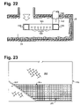
In FIG. 21 a further, generally U-shaped diffuser 185 is seen, again looking downward into the air outlet duct 24. An exhaust connection to the diffuser is diagrammatically indicated at 187. Holes 189 along the length of the diffuser direct hot exhaust in the directions indicated by the unnumbered arrows.
A side view of the diffuser 185 of FIG. 21 is illustrated in FIG. 22 . There the tailpipe 190 of the generator-driving internal combustion engine (not shown) is seen extending through an upper surface of the plenum where a coupling 192, that may be welded in place, connects the tailpipe 190 to the diffuser 185. In the case of the diffuser 185 shown in FIG. 22 , the diffuser is formed from cut and welded sections. Various shapes and configurations, suited to particular installations, can be obtained.
Use of a diffuser such as the diffusers 260, 280, 290, 175 and 185 results in well-mixed gases escaping the duct 24 without hot spots. In addition, each of the diffusers 60, 80, 90, 175 and 185 converts the typical “putt, putt” exhaust sound to a steady hum.
Shown in FIG. 23 , the embodiment illustrated in FIGS. 15 and 16 has an air intake opening 301 formed in the right hand side panel 303 of the box 115 as illustrated in FIG. 23 . Optional screening 305 is shown to keep animals out of the ducts. The box 115 of the particular embodiment is notched on each side as shown at 307 to accommodate the wheel wells of a short bed pickup truck.
In FIG. 24 the floor of the tank containment compartment 121 has been removed and the cold air duct 320 can be seen extending below the compartment to an opening 322 that provides engine and generator cooling air to the generator 10 and combustion air to the generator drive engine. The partitioning wall 324 is shown having a pair of parallel seals 326 extending along its upper edge. To the left of the wall 324 in FIG. 24 is shown the hot air opening 328 that receives warm cooling air from the generator 10 into the duct 330 that extends below the generator 10 to an upright duct portion 332.
In FIG. 24 the optional screening shown covering the duct 330 in FIG. 24 is broken away and a diffuser 334 is seen having an intake pipe 336 for communication with the tail pipe of the internal combustion engine that drives the generator. Small holes 338 are formed in a series along the diffuser 334, which in this case is an L-shaped hollow, rectangular in cross section diffuser capped at its end 340. From the duct 330 intermixed warm cooling air and hot exhaust moves to the upright duct portion 332 and escapes via the opening 119 of FIG. 16 .
The embodiment of FIGS. 15 and 16 are particularly suited for such uses as houseboats, large cabin cruisers and the like where noxious fumes raise the possibility of asphyxiation, particularly when occupants sleep and the generator runs. As shown in FIG. 17 , an installation of a generator-tool box combination of the kind illustrated in FIG. 15 on the uppermost deck 128 well above living and sleeping quarters 129. The upward emission of the exhaust-cooling air mix further moves the carbon monoxide of the exhaust away from the boat inhabitants and where it is most likely to be swept away by the breeze.
In one further embodiment illustrated in FIGS. 25 and 26 , cold air is drawn into an enclosure 401 shown in FIG. 25 with its front cover removed. Cold air is drawn into the enclosure through an opening 403 seen in FIG. 25 . A duct 404 directs the cold air internally of the enclosure 401 where it is drawn into the cool air supply duct 406 formed below the location for the generator defined by the supporting rim 408. As previously, the cool air is drawn in to the engine-generator set for cooling and aspiration. Warmed cooling air is expelled into a warm air duct 410 below the generator where it is admixed with hot exhaust as previously. The mix of hot exhaust and warm air travels from the duct 410 to an upright duct 412 seen in FIG. 25 and escapes through an opening 414 in a sidewall 416 of the enclosure 401.
The foregoing descriptions of at least one preferred embodiment are exemplary and not intended to limit the claimed invention. Obvious modifications that do not depart from the spirit and scope of the invention as claimed will be apparent to those skilled in the art. The toolbox containing a generator can afford portability by being movable from one truck to another. Also the generator is easily accessible for repairs. In one embodiment, the toolbox is detachable from the generator and support plenum so as to lift away from the generator and enable access to the generator for repairs. Further, with appropriate hinging, the toolbox lid can be opened sufficiently to permit the generator to be lifted free of the box for major repairs or simply for movement to a new site. Where the toolbox and the generator support plenum are built as a single unit as in the exemplary embodiment of FIGS. 7 and 8 , the box-plenum combination can be sold shipped as a unit. On the other hand, where the user already has a toolbox, the separate plenum in or under the toolbox can be provided more economically than the provision of a combined box and plenum.
Claims (1)
1. A generator support plenum and generator enclosing box including:
(a) an upper support surface for bearing the weight of a generator;
(b) a lower surface on which, in use, the plenum rests;
(c) an air intake opening into the plenum opening to atmosphere;
(d) an air intake duct through the plenum from the air intake opening;
(e) an opening out of the plenum from the air intake duct and located for alignment with air intake of the generator;
(f) a gas outlet opening from the plenum to atmosphere;
(g) a gas outlet duct through the plenum to the gas outlet opening;
(h) an opening into the plenum to the gas outlet duct and located for alignment with a cooling air outlet of the generator;
(i) a diffuser in the gas outlet duct located to receive engine exhaust gas from an internal combustion engine driving the generator;
(j) soundproofing on interior surfaces of at least one of the air intake and gas outlet ducts; and
(k) the plenum being located outside the generator enclosing box in supporting relation to the box and a generator enclosed in the box, a first opening through a wall of the box in registry with the opening out of the plenum from the air intake duct, and a second opening through a wall of the box in registry with the opening into the plenum to the gas outlet duct.
Priority Applications (2)
| Application Number | Priority Date | Filing Date | Title |
|---|---|---|---|
| US10/845,305 US7482705B2 (en) | 2003-05-12 | 2004-05-12 | Generator support plenum |
| US12/009,341 US20080129053A1 (en) | 2004-05-12 | 2008-02-07 | Engine-generator set |
Applications Claiming Priority (2)
| Application Number | Priority Date | Filing Date | Title |
|---|---|---|---|
| US47001103P | 2003-05-12 | 2003-05-12 | |
| US10/845,305 US7482705B2 (en) | 2003-05-12 | 2004-05-12 | Generator support plenum |
Related Child Applications (1)
| Application Number | Title | Priority Date | Filing Date |
|---|---|---|---|
| US12/009,341 Division US20080129053A1 (en) | 2004-05-12 | 2008-02-07 | Engine-generator set |
Publications (2)
| Publication Number | Publication Date |
|---|---|
| US20050005601A1 US20050005601A1 (en) | 2005-01-13 |
| US7482705B2 true US7482705B2 (en) | 2009-01-27 |
Family
ID=33567430
Family Applications (1)
| Application Number | Title | Priority Date | Filing Date |
|---|---|---|---|
| US10/845,305 Expired - Fee Related US7482705B2 (en) | 2003-05-12 | 2004-05-12 | Generator support plenum |
Country Status (1)
| Country | Link |
|---|---|
| US (1) | US7482705B2 (en) |
Cited By (16)
| Publication number | Priority date | Publication date | Assignee | Title |
|---|---|---|---|---|
| US20110308236A1 (en) * | 2010-06-18 | 2011-12-22 | Briggs & Stratton Corporation | Muffler and engine system |
| US20130314872A1 (en) * | 2011-02-15 | 2013-11-28 | Keisuke Kawakita | Packaged Engine Working Machine |
| US8806853B2 (en) | 2012-12-05 | 2014-08-19 | Cummins Powergen Ip, Inc. | System and method for SCR inducement |
| US8872361B2 (en) | 2012-01-25 | 2014-10-28 | Briggs & Stratton Corporation | Standby generators including compressed fiberglass components |
| US9121319B2 (en) | 2012-10-16 | 2015-09-01 | Universal Acoustic & Emission Technologies | Low pressure drop, high efficiency spark or particulate arresting devices and methods of use |
| US9221016B2 (en) | 2012-12-05 | 2015-12-29 | Cummins Cal Pacific, Llc | Exhaust aftertreatment packaging for a diesel genset |
| US9333466B2 (en) | 2012-12-05 | 2016-05-10 | Cummins Powergen Ip, Inc. | Diesel exhaust fluid injector assembly |
| US9482154B2 (en) | 2012-12-05 | 2016-11-01 | Cummins Cal Pacific, Llc | Exhaust gas collector for an exhaust aftertreatment system |
| USD773395S1 (en) | 2014-09-26 | 2016-12-06 | Cummins Inc. | Genset enclosure |
| US9771847B2 (en) | 2012-12-05 | 2017-09-26 | Cummins Cal Pacific, Llc | Integrated load bank and exhaust heater system with load shed capability for a diesel genset exhaust aftertreatment system |
| US10079526B2 (en) | 2013-09-27 | 2018-09-18 | Cummins, Inc. | Electrical power generation system with multiple path cooling |
| US10184372B2 (en) | 2016-05-23 | 2019-01-22 | Honeywell International Inc. | Exhaust systems and methods for gas turbine engine |
| US10557402B2 (en) * | 2013-03-15 | 2020-02-11 | Kohler Co. | Noise suppression systems |
| US10927732B2 (en) | 2018-03-28 | 2021-02-23 | Cummins Power Generation Ip, Inc. | Low noise enclosure |
| US11591977B2 (en) | 2020-06-03 | 2023-02-28 | Briggs & Stratton, Llc | Inverter generator |
| US11705779B2 (en) | 2020-06-03 | 2023-07-18 | Briggs & Stratton, Llc | Inverter generator |
Families Citing this family (5)
| Publication number | Priority date | Publication date | Assignee | Title |
|---|---|---|---|---|
| US20080129053A1 (en) * | 2004-05-12 | 2008-06-05 | Piercey Gerald S | Engine-generator set |
| ATE550528T1 (en) * | 2006-09-07 | 2012-04-15 | Volvo Trucks North America Inc | EXHAUST DIFFUSER FOR A TRUCK |
| US8186314B2 (en) * | 2007-11-20 | 2012-05-29 | Briggs & Stratton Corporation | Generator cooling system and method |
| US20090194041A1 (en) * | 2007-12-12 | 2009-08-06 | Lobsiger Kent A | Air flow arrangement for two diesel generator sets in shipping container |
| GB2504656A (en) * | 2012-06-11 | 2014-02-12 | Cosworth Ltd | Portable power generation apparatus |
Citations (95)
| Publication number | Priority date | Publication date | Assignee | Title |
|---|---|---|---|---|
| US1484526A (en) * | 1921-05-03 | 1924-02-19 | Michael J O'connor | Muffler |
| US1947713A (en) * | 1931-08-17 | 1934-02-20 | Marjorie Teakle Gumpper | Housing for a motor-generator set |
| US2019026A (en) * | 1932-10-22 | 1935-10-29 | Electric Boat Co | Electric drive |
| US2177687A (en) * | 1937-11-19 | 1939-10-31 | Warner Bros | Electric generator unit |
| US2789234A (en) * | 1956-01-16 | 1957-04-16 | Eastern Malleable Iron Company | Auxiliary power unit for vehicles |
| US2832430A (en) * | 1954-04-23 | 1958-04-29 | Robert S Coombs | Sound muffler device for exhausts of internal combustion engines |
| US3159238A (en) * | 1960-12-01 | 1964-12-01 | Curtiss Wright Corp | Diffuser screen with heat-insulating rungs for exhaust noise suppressor for reactionengines |
| US3227240A (en) * | 1964-05-04 | 1966-01-04 | Gen Electric | Air mingling sound suppressor for jet engine |
| US3386528A (en) * | 1964-01-04 | 1968-06-04 | Gruenzweig & Hartmann | Jet engine sound suppressor with coanda effect deflector |
| US3396535A (en) * | 1966-06-16 | 1968-08-13 | Louis W. Milos | Engine exhaust system |
| US3429281A (en) * | 1967-04-21 | 1969-02-25 | Pullman Inc | Refrigerated container support and generator housings for flat deck railway cars |
| US4007587A (en) * | 1975-11-19 | 1977-02-15 | Avco Corporation | Apparatus for and method of suppressing infrared radiation emitted from gas turbine engine |
| US4018046A (en) * | 1975-07-17 | 1977-04-19 | Avco Corporation | Infrared radiation suppressor for gas turbine engine |
| US4099375A (en) * | 1977-02-03 | 1978-07-11 | The United States Of America As Represented By The Secretary Of The Navy | Exhaust plume reduction and cooling system |
| US4128769A (en) * | 1976-09-27 | 1978-12-05 | The Garrett Corporation | Eductor muffler |
| US4136432A (en) * | 1977-01-13 | 1979-01-30 | Melley Energy Systems, Inc. | Mobile electric power generating systems |
| US4147230A (en) * | 1978-04-14 | 1979-04-03 | Nelson Industries, Inc. | Combination spark arrestor and aspirating muffler |
| US4181347A (en) * | 1977-08-22 | 1980-01-01 | Synergetics, Inc. | Mobile computerized tomography unit |
| US4191356A (en) * | 1978-06-08 | 1980-03-04 | Caterpillar Tractor Co. | Engine mounting base |
| US4192402A (en) * | 1977-05-27 | 1980-03-11 | Honda Giken Kogyo Kabushiki Kaisha | Muffler for internal combustion engines |
| US4215537A (en) * | 1978-07-27 | 1980-08-05 | Avco Corporation | Apparatus for and method of suppressing infrared radiation emitted from gas turbine engine |
| US4312480A (en) * | 1979-11-26 | 1982-01-26 | Hughes Helicopters, Inc. | Radiation shielding and gas diffusion apparatus |
| US4415066A (en) * | 1980-06-05 | 1983-11-15 | Mensik Alphonse J | Manhole service vehicle |
| US4449746A (en) * | 1977-08-22 | 1984-05-22 | Synergetics, Inc. | Mobile computerized tomography unit |
| US4454837A (en) * | 1982-11-12 | 1984-06-19 | Moore & Sons, Inc. | Truck for transporting boxes of poultry |
| US4487289A (en) * | 1982-03-01 | 1984-12-11 | Nelson Industries, Inc. | Exhaust muffler with protective shield |
| US4661734A (en) * | 1985-09-10 | 1987-04-28 | General Electric Company | Dynamoelectric machine |
| US4694190A (en) * | 1985-12-23 | 1987-09-15 | General Electric Company | Integral generator housing and base for a turbine generator |
| US4698975A (en) | 1984-07-16 | 1987-10-13 | Honda Giken Kogyo Kabushiki Kaisha | Engine-operated machine |
| US4747467A (en) * | 1986-04-01 | 1988-05-31 | Allied-Signal Inc. | Turbine engine noise suppression apparatus and methods |
| US4792014A (en) * | 1987-12-24 | 1988-12-20 | Shin Seng Lin | Tail pipe for drafting engine exhaust gas |
| US4835405A (en) * | 1987-11-30 | 1989-05-30 | Onan Corporation | Generator set and method |
| US4992669A (en) * | 1989-02-16 | 1991-02-12 | Parmley Daniel W | Modular energy system |
| US5058704A (en) * | 1988-11-21 | 1991-10-22 | Yu Chuen Huan | Turbo jet muffler |
| US5162620A (en) * | 1989-11-28 | 1992-11-10 | Allied-Signal Inc. | Dual flow turbine engine muffler |
| US5198625A (en) * | 1991-03-25 | 1993-03-30 | Alexander Borla | Exhaust muffler for internal combustion engines |
| US5227593A (en) * | 1990-09-12 | 1993-07-13 | Suzuki Kabushiki Kaisha | Muffler assembly for engine |
| US5533869A (en) * | 1994-11-28 | 1996-07-09 | Homelite, Inc. | Power tool exhaust cooling system |
| US5590806A (en) * | 1995-12-26 | 1997-01-07 | Carrier Corporation | Fuel fill pipe shelf for a generator set fuel tank |
| US5620620A (en) * | 1995-02-03 | 1997-04-15 | Miller Group, Ltd. | Base with internal foot access |
| US5620111A (en) * | 1994-08-22 | 1997-04-15 | Mgs, Inc. | Distortion-resistant generator support base and storage tank assembly |
| US5642702A (en) | 1995-07-21 | 1997-07-01 | Honda Giken Kogyo Kabushiki Kaisha | Generator set |
| US5663537A (en) * | 1995-05-16 | 1997-09-02 | Ko; Tse-Hao | Assembly of an exhaust pipe unit and a muffling device |
| US5678512A (en) * | 1996-11-29 | 1997-10-21 | Carrier Corporation | Cooling air flow system for a self contained motor generator set |
| US5694889A (en) | 1995-05-08 | 1997-12-09 | Ball; Ronald C. | Electrical generator set |
| US5731687A (en) | 1995-04-20 | 1998-03-24 | Honda Giken Kogyo Kabushiki Kaisha | Generator assembly |
| US5740670A (en) * | 1995-04-10 | 1998-04-21 | Woods; Woodrow | Water jacketed exhaust pipe for marine exhaust systems |
| US5744940A (en) * | 1995-12-26 | 1998-04-28 | Carrier Corporation | Fuel tank having pass through conduits |
| US5762232A (en) * | 1996-12-11 | 1998-06-09 | Carrier Corporation | Fuel tank having integral structural framework |
| US5804946A (en) * | 1996-11-19 | 1998-09-08 | Carrier Corporation | Dual tower fuel tank for a motor generator set |
| US5869793A (en) * | 1996-12-11 | 1999-02-09 | Supertrapp Industries, Inc. | Oval shaped spark arresting muffler for engines |
| US5899174A (en) | 1998-02-06 | 1999-05-04 | Anderson; Wayne A. | Enclosed engine generator set |
| US5929394A (en) | 1997-10-07 | 1999-07-27 | Westerbeke Corporation | Sound enclosure |
| US5960637A (en) * | 1998-05-04 | 1999-10-05 | Carrier Corporation | Trailer refrigeration unit with pivotally mounted compressor and engine/generator set |
| US6035633A (en) * | 1995-04-10 | 2000-03-14 | Woods; Woodrow E. | Water jacketed exhaust pipe for marine exhaust systems |
| US6091160A (en) * | 1998-01-19 | 2000-07-18 | Honda Giken Kogyo Kabushiki Kaisha | Portable generator |
| US6100599A (en) * | 1998-01-19 | 2000-08-08 | Honda Giken Kogyo Kabushiki Kaisha | Portable generator |
| US6103995A (en) * | 1998-12-10 | 2000-08-15 | Illinois Tool Works Inc. | Mounting bracket for engine-driven welder |
| US6134879A (en) * | 1989-12-21 | 2000-10-24 | United Technologies Corporation | Suppression system for a gas turbine engine |
| US6308914B1 (en) * | 1999-03-11 | 2001-10-30 | Gkn Westland Helicopters Limited | Apparatus for the suppression of infra red emissions from an engine |
| US20020000342A1 (en) | 2000-06-22 | 2002-01-03 | Masao Yamada | Soundproof type engine driven work machine |
| US6376944B1 (en) | 2000-07-11 | 2002-04-23 | Eagle-Picher Industries, Inc. | Electrical power generator |
| US6385967B1 (en) * | 2000-05-31 | 2002-05-14 | Shun-Lai Chen | Exhaust pipe for motor vehicle muffler |
| US20020121818A1 (en) | 2001-03-01 | 2002-09-05 | Chris Turner | Air flow arrangement for a stand-by electric generator |
| US20020121780A1 (en) | 2000-11-07 | 2002-09-05 | Westerbeke John H. | Marine power generation and engine cooling |
| US6520124B2 (en) * | 2000-12-13 | 2003-02-18 | Tramont Corporation | Double walled fuel tank with integral generator set mounting frame |
| US6532398B2 (en) * | 1998-10-23 | 2003-03-11 | Kouken Company, Limited | Method for installing and removing automatic lift-type mobile facility, method of automatic lift-type power generation, and automatic lift-type mobile facility |
| US20030070651A1 (en) * | 2001-10-11 | 2003-04-17 | Fuji Jukogyo Kabushiki Kaisha | Soundproofed engine generator |
| US20030121722A1 (en) * | 2002-01-02 | 2003-07-03 | Advanced Car Specialties Limited | Exhaust gas muffler |
| US6606854B1 (en) * | 1999-01-04 | 2003-08-19 | Allison Advanced Development Company | Exhaust mixer and apparatus using same |
| US20030205096A1 (en) * | 2002-05-03 | 2003-11-06 | Gehner Gerrick S. | Method and apparatus for mixing gases |
| US6765304B2 (en) * | 2001-09-26 | 2004-07-20 | General Electric Co. | Mobile power generation unit |
| US20050035121A1 (en) * | 2002-09-12 | 2005-02-17 | Power Generation & Engineering, Inc. | Fire resistant base tank for mounting a generator |
| US20050224284A1 (en) * | 2004-04-07 | 2005-10-13 | Syuji Ohno | Engine exhaust muffler with exhaust emission control function |
| US20050241874A1 (en) * | 2002-06-28 | 2005-11-03 | Giat Industries | Device to reduce the visible and infrared signature of a military vehicle |
| US20050252459A1 (en) * | 2004-05-14 | 2005-11-17 | Coleman Powermate, Inc. | Generator having a plastic frame |
| US20050274117A1 (en) * | 2004-06-10 | 2005-12-15 | Honeywell International Inc. | System & method for dumping surge flow into eductor primary nozzle for free turbine |
| US20050284292A1 (en) * | 2004-06-24 | 2005-12-29 | Ruan Ying G | Exhaust gas cooler and particulate scrubbing system |
| US7017690B2 (en) * | 2000-09-25 | 2006-03-28 | Its Bus, Inc. | Platforms for sustainable transportation |
| US7049707B2 (en) * | 2002-11-21 | 2006-05-23 | Energy & Engine Technology Corporation | Auxiliary power unit for a diesel powered transport vehicle |
| US7066170B1 (en) * | 2000-10-31 | 2006-06-27 | Travis Industries, Inc. | Apparatuses and methods for balancing combustion air and exhaust gas for use with a direct-vent heater appliance |
| US7081682B2 (en) * | 2001-08-08 | 2006-07-25 | General Electric Company | Portable power modules and related systems |
| US7111448B2 (en) * | 2001-12-07 | 2006-09-26 | Anderson Jack H | Jet nozzle mixer |
| US7122913B2 (en) * | 2004-07-09 | 2006-10-17 | Wittmar Engineering And Construction, Inc. | Modular power generation apparatus and method |
| US20060237242A1 (en) * | 2000-09-25 | 2006-10-26 | Burke Robert J | Lightweight surface vehicle |
| US7191792B2 (en) * | 2003-09-19 | 2007-03-20 | Ingersoll-Rand Company | Compressor assembly |
| US20070068167A1 (en) * | 2005-09-27 | 2007-03-29 | United Technologies Corporation | Turbine exhaust catalyst |
| US7221061B2 (en) * | 2002-12-02 | 2007-05-22 | Caterpillar Inc | Power generation system having an external process module |
| US7245033B2 (en) * | 2002-11-21 | 2007-07-17 | Energy & Engine Technology Corporation | Auxiliary heating and air conditioning unit for a diesel powered transport vehicle |
| US20070176426A1 (en) * | 2003-07-10 | 2007-08-02 | Tadafumi Hirose | Engine-driven work machine |
| US20070204614A1 (en) * | 2006-03-03 | 2007-09-06 | Proliance International, Inc. | Method for cooling an internal combustion engine having exhaust gas recirculation and charge air cooling |
| US20070245725A1 (en) * | 2006-04-25 | 2007-10-25 | International Truck Intellectual Property Company, Llc | Micro-venturi exhaust cooling device |
| US20070267870A1 (en) * | 2004-01-10 | 2007-11-22 | Gary Carter, Sr. | Multifunction integrated portable power and utility apparatus |
| US7399455B2 (en) * | 2003-03-19 | 2008-07-15 | Guo Xiang Fan | Exhaust filter system for non-road engine |
| US7398747B2 (en) * | 2006-08-25 | 2008-07-15 | Honda Motor Co., Ltd. | Engine-driven work machine |
Family Cites Families (4)
| Publication number | Priority date | Publication date | Assignee | Title |
|---|---|---|---|---|
| US20080129053A1 (en) * | 2004-05-12 | 2008-06-05 | Piercey Gerald S | Engine-generator set |
| CA2595831C (en) * | 2005-02-02 | 2013-08-06 | Oglesby & Butler Research & Development Limited | A device for vaporising vaporisable matter |
| US20080023965A1 (en) * | 2006-07-25 | 2008-01-31 | Black Roak Systems Llc | Auxiliary power unit for transportation vehicle |
| US7878298B2 (en) * | 2006-12-18 | 2011-02-01 | GM Global Technology Operations LLC | Fuel-cell exhaust system |
-
2004
- 2004-05-12 US US10/845,305 patent/US7482705B2/en not_active Expired - Fee Related
Patent Citations (109)
| Publication number | Priority date | Publication date | Assignee | Title |
|---|---|---|---|---|
| US1484526A (en) * | 1921-05-03 | 1924-02-19 | Michael J O'connor | Muffler |
| US1947713A (en) * | 1931-08-17 | 1934-02-20 | Marjorie Teakle Gumpper | Housing for a motor-generator set |
| US2019026A (en) * | 1932-10-22 | 1935-10-29 | Electric Boat Co | Electric drive |
| US2177687A (en) * | 1937-11-19 | 1939-10-31 | Warner Bros | Electric generator unit |
| US2832430A (en) * | 1954-04-23 | 1958-04-29 | Robert S Coombs | Sound muffler device for exhausts of internal combustion engines |
| US2789234A (en) * | 1956-01-16 | 1957-04-16 | Eastern Malleable Iron Company | Auxiliary power unit for vehicles |
| US3159238A (en) * | 1960-12-01 | 1964-12-01 | Curtiss Wright Corp | Diffuser screen with heat-insulating rungs for exhaust noise suppressor for reactionengines |
| US3386528A (en) * | 1964-01-04 | 1968-06-04 | Gruenzweig & Hartmann | Jet engine sound suppressor with coanda effect deflector |
| US3227240A (en) * | 1964-05-04 | 1966-01-04 | Gen Electric | Air mingling sound suppressor for jet engine |
| US3396535A (en) * | 1966-06-16 | 1968-08-13 | Louis W. Milos | Engine exhaust system |
| US3429281A (en) * | 1967-04-21 | 1969-02-25 | Pullman Inc | Refrigerated container support and generator housings for flat deck railway cars |
| US4018046A (en) * | 1975-07-17 | 1977-04-19 | Avco Corporation | Infrared radiation suppressor for gas turbine engine |
| US4007587A (en) * | 1975-11-19 | 1977-02-15 | Avco Corporation | Apparatus for and method of suppressing infrared radiation emitted from gas turbine engine |
| US4128769A (en) * | 1976-09-27 | 1978-12-05 | The Garrett Corporation | Eductor muffler |
| US4136432A (en) * | 1977-01-13 | 1979-01-30 | Melley Energy Systems, Inc. | Mobile electric power generating systems |
| US4099375A (en) * | 1977-02-03 | 1978-07-11 | The United States Of America As Represented By The Secretary Of The Navy | Exhaust plume reduction and cooling system |
| US4192402A (en) * | 1977-05-27 | 1980-03-11 | Honda Giken Kogyo Kabushiki Kaisha | Muffler for internal combustion engines |
| US4449746A (en) * | 1977-08-22 | 1984-05-22 | Synergetics, Inc. | Mobile computerized tomography unit |
| US4181347A (en) * | 1977-08-22 | 1980-01-01 | Synergetics, Inc. | Mobile computerized tomography unit |
| US4147230A (en) * | 1978-04-14 | 1979-04-03 | Nelson Industries, Inc. | Combination spark arrestor and aspirating muffler |
| US4191356A (en) * | 1978-06-08 | 1980-03-04 | Caterpillar Tractor Co. | Engine mounting base |
| US4215537A (en) * | 1978-07-27 | 1980-08-05 | Avco Corporation | Apparatus for and method of suppressing infrared radiation emitted from gas turbine engine |
| US4312480A (en) * | 1979-11-26 | 1982-01-26 | Hughes Helicopters, Inc. | Radiation shielding and gas diffusion apparatus |
| US4415066A (en) * | 1980-06-05 | 1983-11-15 | Mensik Alphonse J | Manhole service vehicle |
| US4487289A (en) * | 1982-03-01 | 1984-12-11 | Nelson Industries, Inc. | Exhaust muffler with protective shield |
| US4454837A (en) * | 1982-11-12 | 1984-06-19 | Moore & Sons, Inc. | Truck for transporting boxes of poultry |
| US4698975A (en) | 1984-07-16 | 1987-10-13 | Honda Giken Kogyo Kabushiki Kaisha | Engine-operated machine |
| US4661734A (en) * | 1985-09-10 | 1987-04-28 | General Electric Company | Dynamoelectric machine |
| US4694190A (en) * | 1985-12-23 | 1987-09-15 | General Electric Company | Integral generator housing and base for a turbine generator |
| US4747467A (en) * | 1986-04-01 | 1988-05-31 | Allied-Signal Inc. | Turbine engine noise suppression apparatus and methods |
| US4835405A (en) * | 1987-11-30 | 1989-05-30 | Onan Corporation | Generator set and method |
| US4792014A (en) * | 1987-12-24 | 1988-12-20 | Shin Seng Lin | Tail pipe for drafting engine exhaust gas |
| US5058704A (en) * | 1988-11-21 | 1991-10-22 | Yu Chuen Huan | Turbo jet muffler |
| US4992669A (en) * | 1989-02-16 | 1991-02-12 | Parmley Daniel W | Modular energy system |
| US5162620A (en) * | 1989-11-28 | 1992-11-10 | Allied-Signal Inc. | Dual flow turbine engine muffler |
| US6134879A (en) * | 1989-12-21 | 2000-10-24 | United Technologies Corporation | Suppression system for a gas turbine engine |
| US5227593A (en) * | 1990-09-12 | 1993-07-13 | Suzuki Kabushiki Kaisha | Muffler assembly for engine |
| US5198625A (en) * | 1991-03-25 | 1993-03-30 | Alexander Borla | Exhaust muffler for internal combustion engines |
| US5620111A (en) * | 1994-08-22 | 1997-04-15 | Mgs, Inc. | Distortion-resistant generator support base and storage tank assembly |
| US5533869A (en) * | 1994-11-28 | 1996-07-09 | Homelite, Inc. | Power tool exhaust cooling system |
| US5620620A (en) * | 1995-02-03 | 1997-04-15 | Miller Group, Ltd. | Base with internal foot access |
| US6035633A (en) * | 1995-04-10 | 2000-03-14 | Woods; Woodrow E. | Water jacketed exhaust pipe for marine exhaust systems |
| US5740670A (en) * | 1995-04-10 | 1998-04-21 | Woods; Woodrow | Water jacketed exhaust pipe for marine exhaust systems |
| US5731687A (en) | 1995-04-20 | 1998-03-24 | Honda Giken Kogyo Kabushiki Kaisha | Generator assembly |
| US5694889A (en) | 1995-05-08 | 1997-12-09 | Ball; Ronald C. | Electrical generator set |
| US5663537A (en) * | 1995-05-16 | 1997-09-02 | Ko; Tse-Hao | Assembly of an exhaust pipe unit and a muffling device |
| US5642702A (en) | 1995-07-21 | 1997-07-01 | Honda Giken Kogyo Kabushiki Kaisha | Generator set |
| US5744940A (en) * | 1995-12-26 | 1998-04-28 | Carrier Corporation | Fuel tank having pass through conduits |
| US5590806A (en) * | 1995-12-26 | 1997-01-07 | Carrier Corporation | Fuel fill pipe shelf for a generator set fuel tank |
| US5804946A (en) * | 1996-11-19 | 1998-09-08 | Carrier Corporation | Dual tower fuel tank for a motor generator set |
| US5678512A (en) * | 1996-11-29 | 1997-10-21 | Carrier Corporation | Cooling air flow system for a self contained motor generator set |
| US5762232A (en) * | 1996-12-11 | 1998-06-09 | Carrier Corporation | Fuel tank having integral structural framework |
| US5869793A (en) * | 1996-12-11 | 1999-02-09 | Supertrapp Industries, Inc. | Oval shaped spark arresting muffler for engines |
| US5929394A (en) | 1997-10-07 | 1999-07-27 | Westerbeke Corporation | Sound enclosure |
| US6091160A (en) * | 1998-01-19 | 2000-07-18 | Honda Giken Kogyo Kabushiki Kaisha | Portable generator |
| US6100599A (en) * | 1998-01-19 | 2000-08-08 | Honda Giken Kogyo Kabushiki Kaisha | Portable generator |
| US5899174A (en) | 1998-02-06 | 1999-05-04 | Anderson; Wayne A. | Enclosed engine generator set |
| US5960637A (en) * | 1998-05-04 | 1999-10-05 | Carrier Corporation | Trailer refrigeration unit with pivotally mounted compressor and engine/generator set |
| US6546312B1 (en) * | 1998-10-23 | 2003-04-08 | Kouken Company, Limited | Method for installing and removing automatic lift-type mobile facility, method of automatic lift-type power generation, and automatic lift-type mobile facility |
| US6532398B2 (en) * | 1998-10-23 | 2003-03-11 | Kouken Company, Limited | Method for installing and removing automatic lift-type mobile facility, method of automatic lift-type power generation, and automatic lift-type mobile facility |
| US6608392B2 (en) * | 1998-10-23 | 2003-08-19 | Kouken Company, Limited | Method for installing and removing automatic lift-type mobile facility, method of automatic lift-type power generation, and automatic lift-type mobile facility |
| US6103995A (en) * | 1998-12-10 | 2000-08-15 | Illinois Tool Works Inc. | Mounting bracket for engine-driven welder |
| US6606854B1 (en) * | 1999-01-04 | 2003-08-19 | Allison Advanced Development Company | Exhaust mixer and apparatus using same |
| US20040068981A1 (en) * | 1999-01-04 | 2004-04-15 | Siefker Robert G. | Exhaust mixer and apparatus using same |
| US6308914B1 (en) * | 1999-03-11 | 2001-10-30 | Gkn Westland Helicopters Limited | Apparatus for the suppression of infra red emissions from an engine |
| US6385967B1 (en) * | 2000-05-31 | 2002-05-14 | Shun-Lai Chen | Exhaust pipe for motor vehicle muffler |
| US20020000342A1 (en) | 2000-06-22 | 2002-01-03 | Masao Yamada | Soundproof type engine driven work machine |
| US6376944B1 (en) | 2000-07-11 | 2002-04-23 | Eagle-Picher Industries, Inc. | Electrical power generator |
| US20060237242A1 (en) * | 2000-09-25 | 2006-10-26 | Burke Robert J | Lightweight surface vehicle |
| US7017690B2 (en) * | 2000-09-25 | 2006-03-28 | Its Bus, Inc. | Platforms for sustainable transportation |
| US20070101987A1 (en) * | 2000-10-31 | 2007-05-10 | Travis Industries, Inc. | Apparatuses and methods for balancing combustion air and exhaust gas for use with a direct-vent heater appliance |
| US7066170B1 (en) * | 2000-10-31 | 2006-06-27 | Travis Industries, Inc. | Apparatuses and methods for balancing combustion air and exhaust gas for use with a direct-vent heater appliance |
| US20020121780A1 (en) | 2000-11-07 | 2002-09-05 | Westerbeke John H. | Marine power generation and engine cooling |
| US6520124B2 (en) * | 2000-12-13 | 2003-02-18 | Tramont Corporation | Double walled fuel tank with integral generator set mounting frame |
| US20020121818A1 (en) | 2001-03-01 | 2002-09-05 | Chris Turner | Air flow arrangement for a stand-by electric generator |
| US7081682B2 (en) * | 2001-08-08 | 2006-07-25 | General Electric Company | Portable power modules and related systems |
| US6765304B2 (en) * | 2001-09-26 | 2004-07-20 | General Electric Co. | Mobile power generation unit |
| US20030070651A1 (en) * | 2001-10-11 | 2003-04-17 | Fuji Jukogyo Kabushiki Kaisha | Soundproofed engine generator |
| US6792897B2 (en) * | 2001-10-11 | 2004-09-21 | Fuji Jukogyo Kabushiki Kaisha | Soundproofed engine generator |
| US7111448B2 (en) * | 2001-12-07 | 2006-09-26 | Anderson Jack H | Jet nozzle mixer |
| US6832665B2 (en) * | 2002-01-02 | 2004-12-21 | Advanced Car Specialties Limited | Exhaust gas muffler |
| US20050103003A1 (en) * | 2002-01-02 | 2005-05-19 | Advanced Car Specialties Limited | Exhaust gas muffler |
| US20030121722A1 (en) * | 2002-01-02 | 2003-07-03 | Advanced Car Specialties Limited | Exhaust gas muffler |
| US20030205096A1 (en) * | 2002-05-03 | 2003-11-06 | Gehner Gerrick S. | Method and apparatus for mixing gases |
| US6684719B2 (en) * | 2002-05-03 | 2004-02-03 | Caterpillar Inc | Method and apparatus for mixing gases |
| US7100459B2 (en) * | 2002-05-03 | 2006-09-05 | Caterpillar, Inc. | Method and apparatus for mixing gases |
| US6928890B2 (en) * | 2002-05-03 | 2005-08-16 | Caterpillar Inc | Method and apparatus for mixing gases |
| US20040089078A1 (en) * | 2002-05-03 | 2004-05-13 | Caterpillar, Inc. | Method and apparatus for mixing gases |
| US20040093963A1 (en) * | 2002-05-03 | 2004-05-20 | Caterpillar, Inc. | Method and apparatus for mixing gases |
| US20050241874A1 (en) * | 2002-06-28 | 2005-11-03 | Giat Industries | Device to reduce the visible and infrared signature of a military vehicle |
| US20050035121A1 (en) * | 2002-09-12 | 2005-02-17 | Power Generation & Engineering, Inc. | Fire resistant base tank for mounting a generator |
| US7049707B2 (en) * | 2002-11-21 | 2006-05-23 | Energy & Engine Technology Corporation | Auxiliary power unit for a diesel powered transport vehicle |
| US7245033B2 (en) * | 2002-11-21 | 2007-07-17 | Energy & Engine Technology Corporation | Auxiliary heating and air conditioning unit for a diesel powered transport vehicle |
| US7221061B2 (en) * | 2002-12-02 | 2007-05-22 | Caterpillar Inc | Power generation system having an external process module |
| US7399455B2 (en) * | 2003-03-19 | 2008-07-15 | Guo Xiang Fan | Exhaust filter system for non-road engine |
| US20070176426A1 (en) * | 2003-07-10 | 2007-08-02 | Tadafumi Hirose | Engine-driven work machine |
| US7191792B2 (en) * | 2003-09-19 | 2007-03-20 | Ingersoll-Rand Company | Compressor assembly |
| US20070267870A1 (en) * | 2004-01-10 | 2007-11-22 | Gary Carter, Sr. | Multifunction integrated portable power and utility apparatus |
| US20050224284A1 (en) * | 2004-04-07 | 2005-10-13 | Syuji Ohno | Engine exhaust muffler with exhaust emission control function |
| US20050252459A1 (en) * | 2004-05-14 | 2005-11-17 | Coleman Powermate, Inc. | Generator having a plastic frame |
| US7152410B2 (en) * | 2004-06-10 | 2006-12-26 | Honeywell International, Inc. | System and method for dumping surge flow into eductor primary nozzle for free turbine |
| US20050274117A1 (en) * | 2004-06-10 | 2005-12-15 | Honeywell International Inc. | System & method for dumping surge flow into eductor primary nozzle for free turbine |
| US20050284292A1 (en) * | 2004-06-24 | 2005-12-29 | Ruan Ying G | Exhaust gas cooler and particulate scrubbing system |
| US7163571B2 (en) * | 2004-06-24 | 2007-01-16 | Ying Gang Ruan | Exhaust gas cooler and particulate scrubbing system |
| US7122913B2 (en) * | 2004-07-09 | 2006-10-17 | Wittmar Engineering And Construction, Inc. | Modular power generation apparatus and method |
| US20070068167A1 (en) * | 2005-09-27 | 2007-03-29 | United Technologies Corporation | Turbine exhaust catalyst |
| US20070204614A1 (en) * | 2006-03-03 | 2007-09-06 | Proliance International, Inc. | Method for cooling an internal combustion engine having exhaust gas recirculation and charge air cooling |
| US20070245725A1 (en) * | 2006-04-25 | 2007-10-25 | International Truck Intellectual Property Company, Llc | Micro-venturi exhaust cooling device |
| US7398747B2 (en) * | 2006-08-25 | 2008-07-15 | Honda Motor Co., Ltd. | Engine-driven work machine |
Cited By (29)
| Publication number | Priority date | Publication date | Assignee | Title |
|---|---|---|---|---|
| US9605572B2 (en) * | 2010-06-18 | 2017-03-28 | Briggs & Stratton Corporation | Muffler and engine system |
| US8485313B2 (en) * | 2010-06-18 | 2013-07-16 | Briggs & Stratton Corporation | Muffler and engine system |
| US20130277145A1 (en) * | 2010-06-18 | 2013-10-24 | Briggs & Stratton Corporation | Muffler and engine system |
| US20110308236A1 (en) * | 2010-06-18 | 2011-12-22 | Briggs & Stratton Corporation | Muffler and engine system |
| US20130314872A1 (en) * | 2011-02-15 | 2013-11-28 | Keisuke Kawakita | Packaged Engine Working Machine |
| US8963348B2 (en) * | 2011-02-15 | 2015-02-24 | Yanmar Co., Ltd. | Packaged engine working machine |
| US10181770B2 (en) | 2012-01-25 | 2019-01-15 | Briggs & Stratton Corporation | Standby generator with air intake on rear wall and exhaust opening on front wall |
| US8872361B2 (en) | 2012-01-25 | 2014-10-28 | Briggs & Stratton Corporation | Standby generators including compressed fiberglass components |
| US10044243B2 (en) | 2012-01-25 | 2018-08-07 | Briggs & Stratton Corporation | Standby generator with air intake on rear wall and exhaust opening on front wall |
| US9755480B2 (en) | 2012-01-25 | 2017-09-05 | Briggs & Stratton Corporation | Standby generator including enclosure with intake opening in rear wall and exhaust opening in front wall |
| US9431865B2 (en) | 2012-01-25 | 2016-08-30 | Briggs & Stratton Corporation | Standby generator with removable panel |
| US9121319B2 (en) | 2012-10-16 | 2015-09-01 | Universal Acoustic & Emission Technologies | Low pressure drop, high efficiency spark or particulate arresting devices and methods of use |
| US8806853B2 (en) | 2012-12-05 | 2014-08-19 | Cummins Powergen Ip, Inc. | System and method for SCR inducement |
| US9957864B2 (en) | 2012-12-05 | 2018-05-01 | Cummins Distribution Holdco Inc. | System and method for SCR inducement |
| US9482154B2 (en) | 2012-12-05 | 2016-11-01 | Cummins Cal Pacific, Llc | Exhaust gas collector for an exhaust aftertreatment system |
| US9771847B2 (en) | 2012-12-05 | 2017-09-26 | Cummins Cal Pacific, Llc | Integrated load bank and exhaust heater system with load shed capability for a diesel genset exhaust aftertreatment system |
| US9333466B2 (en) | 2012-12-05 | 2016-05-10 | Cummins Powergen Ip, Inc. | Diesel exhaust fluid injector assembly |
| US9221016B2 (en) | 2012-12-05 | 2015-12-29 | Cummins Cal Pacific, Llc | Exhaust aftertreatment packaging for a diesel genset |
| US10260389B2 (en) | 2012-12-05 | 2019-04-16 | Cummins Cal Pacific, Llc | Integrated load bank and exhaust heater system with load shed capability for a diesel genset exhaust aftertreatment system |
| US10557402B2 (en) * | 2013-03-15 | 2020-02-11 | Kohler Co. | Noise suppression systems |
| US10079526B2 (en) | 2013-09-27 | 2018-09-18 | Cummins, Inc. | Electrical power generation system with multiple path cooling |
| US10079525B2 (en) | 2013-09-27 | 2018-09-18 | Cummins, Inc. | Electrical power generation system with multiple path cooling |
| USD773395S1 (en) | 2014-09-26 | 2016-12-06 | Cummins Inc. | Genset enclosure |
| US10184372B2 (en) | 2016-05-23 | 2019-01-22 | Honeywell International Inc. | Exhaust systems and methods for gas turbine engine |
| US10954834B2 (en) | 2016-05-23 | 2021-03-23 | Honeywell International Inc. | Exhaust systems and methods for gas turbine engine |
| US11255239B2 (en) | 2016-05-23 | 2022-02-22 | Honeywell International Inc. | Exhaust systems and methods for gas turbine engine |
| US10927732B2 (en) | 2018-03-28 | 2021-02-23 | Cummins Power Generation Ip, Inc. | Low noise enclosure |
| US11591977B2 (en) | 2020-06-03 | 2023-02-28 | Briggs & Stratton, Llc | Inverter generator |
| US11705779B2 (en) | 2020-06-03 | 2023-07-18 | Briggs & Stratton, Llc | Inverter generator |
Also Published As
| Publication number | Publication date |
|---|---|
| US20050005601A1 (en) | 2005-01-13 |
Similar Documents
| Publication | Publication Date | Title |
|---|---|---|
| US7482705B2 (en) | Generator support plenum | |
| US20080129053A1 (en) | Engine-generator set | |
| US6895903B2 (en) | Air provision systems for portable power modules | |
| US6601542B2 (en) | Containment systems for portable power modules | |
| US7081682B2 (en) | Portable power modules and related systems | |
| US6039009A (en) | Engine-operated generator | |
| US7007966B2 (en) | Air ducts for portable power modules | |
| US4217764A (en) | Roof mounted motor vehicle air conditioner | |
| US5977667A (en) | Engine-operated generator | |
| JP3501006B2 (en) | Arrangement structure of vehicle battery cooling duct | |
| CA1209176A (en) | Vertical shaft engine generator set for a recreational vehicle or the like | |
| JPH05508593A (en) | Automotive battery cooling structure | |
| JP2005324771A (en) | Battery cooling system | |
| US20040134227A1 (en) | Undermount transport temperature control unit | |
| US5908011A (en) | Reduced length engine generator assembly | |
| US6230667B1 (en) | Reduced length engine generator assembly | |
| CN101158314A (en) | Underpan structure of wind cooling electric generating set | |
| US20010002501A1 (en) | Leaf blower | |
| JP2004353610A (en) | Air supply device and forklift equipped with the same | |
| US3799244A (en) | Service vehicle for manhole operation | |
| US5788320A (en) | Hidden installation of a water heater, generator and battery under the floor at the rear of a van | |
| JP3120326B2 (en) | Soundproof engine generator | |
| JP3977231B2 (en) | Ventilation structure of fuel cell vehicle | |
| JPS643777Y2 (en) | ||
| JP2004198023A (en) | Air conditioner unit |
Legal Events
| Date | Code | Title | Description |
|---|---|---|---|
| REMI | Maintenance fee reminder mailed | ||
| LAPS | Lapse for failure to pay maintenance fees | ||
| STCH | Information on status: patent discontinuation |
Free format text: PATENT EXPIRED DUE TO NONPAYMENT OF MAINTENANCE FEES UNDER 37 CFR 1.362 |
|
| FP | Lapsed due to failure to pay maintenance fee |
Effective date: 20130127 |