US7488095B2 - Prism sheet of back light unit for LCD - Google Patents
Prism sheet of back light unit for LCD Download PDFInfo
- Publication number
- US7488095B2 US7488095B2 US10/562,263 US56226303A US7488095B2 US 7488095 B2 US7488095 B2 US 7488095B2 US 56226303 A US56226303 A US 56226303A US 7488095 B2 US7488095 B2 US 7488095B2
- Authority
- US
- United States
- Prior art keywords
- prism sheet
- prism
- peaks
- peak
- structural surface
- Prior art date
- Legal status (The legal status is an assumption and is not a legal conclusion. Google has not performed a legal analysis and makes no representation as to the accuracy of the status listed.)
- Expired - Lifetime, expires
Links
- NIXOWILDQLNWCW-UHFFFAOYSA-M Acrylate Chemical compound [O-]C(=O)C=C NIXOWILDQLNWCW-UHFFFAOYSA-M 0.000 claims description 9
- 229920006254 polymer film Polymers 0.000 claims description 8
- 229920000515 polycarbonate Polymers 0.000 claims description 6
- 239000004417 polycarbonate Substances 0.000 claims description 6
- 229920000728 polyester Polymers 0.000 claims description 6
- 229920005570 flexible polymer Polymers 0.000 claims description 3
- 229920000642 polymer Polymers 0.000 claims description 3
- 229920000915 polyvinyl chloride Polymers 0.000 claims description 3
- 239000004800 polyvinyl chloride Substances 0.000 claims description 3
- 230000003287 optical effect Effects 0.000 abstract description 12
- 230000008878 coupling Effects 0.000 abstract description 10
- 238000010168 coupling process Methods 0.000 abstract description 10
- 238000005859 coupling reaction Methods 0.000 abstract description 10
- 230000005540 biological transmission Effects 0.000 description 14
- 239000010408 film Substances 0.000 description 9
- 238000005286 illumination Methods 0.000 description 8
- 238000010586 diagram Methods 0.000 description 5
- 238000001228 spectrum Methods 0.000 description 5
- 239000010409 thin film Substances 0.000 description 5
- XKRFYHLGVUSROY-UHFFFAOYSA-N Argon Chemical compound [Ar] XKRFYHLGVUSROY-UHFFFAOYSA-N 0.000 description 4
- 230000008901 benefit Effects 0.000 description 4
- 230000008859 change Effects 0.000 description 4
- 238000009792 diffusion process Methods 0.000 description 3
- 229910052786 argon Inorganic materials 0.000 description 2
- 150000001768 cations Chemical class 0.000 description 2
- 230000001066 destructive effect Effects 0.000 description 2
- 230000000694 effects Effects 0.000 description 2
- 239000000463 material Substances 0.000 description 2
- QSHDDOUJBYECFT-UHFFFAOYSA-N mercury Chemical compound [Hg] QSHDDOUJBYECFT-UHFFFAOYSA-N 0.000 description 2
- 238000000034 method Methods 0.000 description 2
- 230000004048 modification Effects 0.000 description 2
- 238000012986 modification Methods 0.000 description 2
- 230000000737 periodic effect Effects 0.000 description 2
- 206010027339 Menstruation irregular Diseases 0.000 description 1
- 238000010521 absorption reaction Methods 0.000 description 1
- 239000003086 colorant Substances 0.000 description 1
- 238000005516 engineering process Methods 0.000 description 1
- 239000000835 fiber Substances 0.000 description 1
- 239000011521 glass Substances 0.000 description 1
- 239000004973 liquid crystal related substance Substances 0.000 description 1
- 239000002861 polymer material Substances 0.000 description 1
- 230000009467 reduction Effects 0.000 description 1
- 238000006748 scratching Methods 0.000 description 1
- 230000002393 scratching effect Effects 0.000 description 1
- 239000000126 substance Substances 0.000 description 1
- WFKWXMTUELFFGS-UHFFFAOYSA-N tungsten Chemical compound [W] WFKWXMTUELFFGS-UHFFFAOYSA-N 0.000 description 1
- 229910052721 tungsten Inorganic materials 0.000 description 1
- 239000010937 tungsten Substances 0.000 description 1
Images


Classifications
-
- G—PHYSICS
- G02—OPTICS
- G02F—OPTICAL DEVICES OR ARRANGEMENTS FOR THE CONTROL OF LIGHT BY MODIFICATION OF THE OPTICAL PROPERTIES OF THE MEDIA OF THE ELEMENTS INVOLVED THEREIN; NON-LINEAR OPTICS; FREQUENCY-CHANGING OF LIGHT; OPTICAL LOGIC ELEMENTS; OPTICAL ANALOGUE/DIGITAL CONVERTERS
- G02F1/00—Devices or arrangements for the control of the intensity, colour, phase, polarisation or direction of light arriving from an independent light source, e.g. switching, gating or modulating; Non-linear optics
- G02F1/01—Devices or arrangements for the control of the intensity, colour, phase, polarisation or direction of light arriving from an independent light source, e.g. switching, gating or modulating; Non-linear optics for the control of the intensity, phase, polarisation or colour
- G02F1/13—Devices or arrangements for the control of the intensity, colour, phase, polarisation or direction of light arriving from an independent light source, e.g. switching, gating or modulating; Non-linear optics for the control of the intensity, phase, polarisation or colour based on liquid crystals, e.g. single liquid crystal display cells
- G02F1/133—Constructional arrangements; Operation of liquid crystal cells; Circuit arrangements
- G02F1/1333—Constructional arrangements; Manufacturing methods
- G02F1/1335—Structural association of cells with optical devices, e.g. polarisers or reflectors
-
- G—PHYSICS
- G02—OPTICS
- G02B—OPTICAL ELEMENTS, SYSTEMS OR APPARATUS
- G02B6/00—Light guides; Structural details of arrangements comprising light guides and other optical elements, e.g. couplings
- G02B6/0001—Light guides; Structural details of arrangements comprising light guides and other optical elements, e.g. couplings specially adapted for lighting devices or systems
- G02B6/0011—Light guides; Structural details of arrangements comprising light guides and other optical elements, e.g. couplings specially adapted for lighting devices or systems the light guides being planar or of plate-like form
- G02B6/0033—Means for improving the coupling-out of light from the light guide
- G02B6/005—Means for improving the coupling-out of light from the light guide provided by one optical element, or plurality thereof, placed on the light output side of the light guide
- G02B6/0053—Prismatic sheet or layer; Brightness enhancement element, sheet or layer
-
- G—PHYSICS
- G02—OPTICS
- G02B—OPTICAL ELEMENTS, SYSTEMS OR APPARATUS
- G02B5/00—Optical elements other than lenses
- G02B5/04—Prisms
- G02B5/045—Prism arrays
-
- G—PHYSICS
- G02—OPTICS
- G02F—OPTICAL DEVICES OR ARRANGEMENTS FOR THE CONTROL OF LIGHT BY MODIFICATION OF THE OPTICAL PROPERTIES OF THE MEDIA OF THE ELEMENTS INVOLVED THEREIN; NON-LINEAR OPTICS; FREQUENCY-CHANGING OF LIGHT; OPTICAL LOGIC ELEMENTS; OPTICAL ANALOGUE/DIGITAL CONVERTERS
- G02F1/00—Devices or arrangements for the control of the intensity, colour, phase, polarisation or direction of light arriving from an independent light source, e.g. switching, gating or modulating; Non-linear optics
- G02F1/01—Devices or arrangements for the control of the intensity, colour, phase, polarisation or direction of light arriving from an independent light source, e.g. switching, gating or modulating; Non-linear optics for the control of the intensity, phase, polarisation or colour
- G02F1/13—Devices or arrangements for the control of the intensity, colour, phase, polarisation or direction of light arriving from an independent light source, e.g. switching, gating or modulating; Non-linear optics for the control of the intensity, phase, polarisation or colour based on liquid crystals, e.g. single liquid crystal display cells
- G02F1/133—Constructional arrangements; Operation of liquid crystal cells; Circuit arrangements
- G02F1/1333—Constructional arrangements; Manufacturing methods
- G02F1/1335—Structural association of cells with optical devices, e.g. polarisers or reflectors
- G02F1/1336—Illuminating devices
- G02F1/133602—Direct backlight
- G02F1/133606—Direct backlight including a specially adapted diffusing, scattering or light controlling members
Definitions
- the present invention relates to a prism sheet of a backlight unit for an LCD, and more particularly, to a prism sheet for reducing Moiré phenomenon caused by a contact between prism sheets by providing a structure to control an optical coupling generated between contact surfaces of prism sheets configured to enhance the front brightness of light emitted from a backlight unit.
- a liquid crystal display that is recently popular as a general display means or a monitor consumes very low electric power and is thin and light since it does not employ the electronic gun. So, in these days, the LCD has been rapidly developed and widely used.
- the LCD Since the LCD cannot emit light by itself, it employs a method controlling light amount by reflecting or transmitting light.
- the light source employed in the transmission type LCD that is widely used is called a backlight unit.
- the performance of the LCD depends seriously on that of the backlight unit.
- FIGS. 1 and 2 are diagrams illustrating structure of a backlight unit employed in the LCD.
- the backlight unit includes a fluorescent lamp 1 , a reflecting plate 2 , a light guide plate 3 , a diffusion sheet 4 , a first prism sheet 5 , a second prism sheet 6 and a protection sheet 7 .
- An LCD panel 8 is mounted on the top of the backlight unit.
- the emitted secondary electrons flow inside a tube of the fluorescent lamp 1 and starts discharge.
- the electrons flowing due to the discharge collide with mercury vapor.
- the mercury vapor is ionized to emit ultraviolet ray and visible light.
- the emitted ultraviolet ray excites fluorescent substance coated on the inner surface of the tube of the fluorescent lamp 1 to emit visible light.
- the emitted visible light travels along the light guide plate 3 that has a slant lower surface.
- a variety of patterns such as a fine dot pattern are printed in order to change the traveling direction of the visible light toward the LCD panel 8 so that light loss is reduced and the light is guided to an upper surface of the light guide plate 3 .
- the light transmitting through the upper surface of the light guide plate 3 includes not only beams emitted perpendicular to the upper surface but also beams emitted slant in various angles.
- a diffusion sheet 4 is placed to diffuse the light that is incident from the light guide plate 3 , thereby preventing the light from being locally concentrated and also functioning to change the direction of the light traveling toward the first prism sheet 5 and to thus reduce a slant angle with respect to the first prism sheet 5 .
- the first prism sheet 5 and the second prism sheet 6 are provided with triangular prisms formed in a predetermined arrangement on the upper surfaces thereof.
- the first prism arrangement of the first prism sheet 5 and the second prism arrangement of the first prism sheet 6 are crossed with each other by a predetermined angle.
- the first prism sheet 5 and the second prism sheet 6 condense the light diffused from the diffusion sheet 4 in the direction perpendicular to the LCD panel 8 . Accordingly, the orthogonal incidence characteristic of the light passing through the first prism sheet 5 and the second prism sheet 6 to the protection sheet 7 can be obtained completely.
- the light passing through the first prism sheet 5 and the second prism sheet 6 travels almost perpendicularly with respect to the first prism sheet 5 and the second prism sheet 6 , so that the brightness distribution on the protection sheet 7 can be obtained uniformly.
- the peaks of the prism sheet are maintained at the same height along the length direction of the stripe shape, so that the optical coupling is made between the peak portion of the first prism sheet 5 positioned at a lower portion and the flat surface of the second prism sheet 6 positioned at an upper portion if the first prism sheet and the second prism sheet are used in fold. So, the moiré phenomenon that a pattern of lines is visibly shown is caused and the quality of image displayed on a screen deteriorates.
- the prism sheet structure adapted to a backlight unit is disclosed as a flexible thin film in Korean patent laid-open publication No. 1987-0005258.
- FIGS. 3A and 3B illustrate a flexible film employed as a prism sheet of the backlight unit.
- This flexible thin film has a structural surface 12 on one side thereof and a flat surface 14 on the other side thereof and is made of transparent polymer material.
- the structural surface 12 of the film includes a linear arrangement of small right-angled isosceles triangular prisms arranged in parallel and is configured to have a plurality of peaks 17 and grooves 18 that are as long as the length of the film 10 as shown in FIGS. 4 and 5 .
- the perpendicular surfaces 20 slant by an angle ( ⁇ ) of about 45° with respect to the adjacent flat surface 14 .
- the incident light that strikes the structural surface 12 or the flat surface 14 in a predetermined angle is fully reflected from the other surface as shown in FIG. 4 . If the light refracted by a first surface strikes a second surface by an angle larger than the critical angle with respect to the normal line, the light is fully reflected.
- the critical angle in air is defined to be arc sine of reciprocity of index of refraction of the material. As shown in FIG. 5 , a great deal of the incident light striking the surface 12 or the surface 14 by an angle larger than the angle range is transmitted and the remainder is reflected. In both cases, the optical absorption due to the material is negligible.
- the light ‘A’ that is incident into each of the flat surfaces 14 formed along a normal line of the flat surface 14 of the flexible thin film is refracted, and fully reflected at the structural surface 12 of the flexible thin film as shown in FIG. 3 .
- Both the light ‘A’ and the normal line ‘N’ lie on the plane perpendicular to the direction P in which the prisms 16 of the structural surface 12 are arranged linearly.
- the light ‘A’ is fully reflected and projected as a reflection light ‘A′’ located on the same plane.
- another light ‘B’ applied to the flat surface 14 on the plane not perpendicular to the direction P is exemplarily shown.
- the incident light B is reflected inside, and projected as the light ‘B’ on another plane defined by the incident light B and the prism direction P.
- the peaks of the prism sheet are maintained at the same height along the length direction of the stripe shape. So, if the first prism sheet and the second prism sheet are used in fold, the optical coupling is made between the peak portion of the first prism sheet positioned at a lower portion and the flat surface of the second prism sheet positioned at an upper portion. So, the moire phenomenon that a pattern of lines is visibly shown caused and the quality of image displayed on a screen deteriorates.
- the present invention is directed to a prism sheet of a backlight unit for an LCD that substantially obviates one or more of the problems due to limitations and disadvantages of the related art.
- An object of the present invention is to provide a prism sheet effectively applicable to a backlight unit.
- Another object of the present invention is to reduce an optical coupling occurring in case peaks of prism sheets of a backlight unit are maintained at the same height along the length direction of the stripe shape and a first prism sheet and a second prism sheet are used in fold, by changing the structure of the prism sheet.
- a further object of the present invention is to reduce moire phenomenon by minimizing an optical coupling caused between prism sheets when the prism sheets are arranged in fold so as to constitute the backlight unit.
- the present invention is characterized by a prism sheet having a structural surface on one side thereof and a flat surface opposing the structural surface on another side thereof, the structural surface including a linear arrangement of right-angled isosceles triangular prisms arranged in parallel and configured to form a plurality of peaks and valleys, each of the prisms having perpendicular surfaces that slant by an angle of approximately 45° with respect to the flat surface,
- the structural surface is configured to have non-planar peaks with a maximum height and a minimum height along a length direction of the peak, and a curved layer having the same cycle as a cycle of height variation of the peak is formed at a boundary surface between the structural surface and the flat surface so as to maintain the right-angled isosceles triangular prisms formed due to a difference between the highest point and the lowest point of each of the peaks to have a predetermined size so that a distance between the valleys is uniform along the length direction.
- the optical coupling caused between the structural surfaces of the corresponding prism sheets is minimized and the moiré patterns can be suppressed or removed, so that highly reliable prism sheets adapted to the backlight unit can be obtained.
- FIG. 1 is a disassembled perspective view of an assembly of a backlight unit employing a conventional prism sheet;
- FIG. 2 is a cross-sectional view of FIG. 1 taken along the line A 1 -A 2 ;
- FIGS. 3A and 3B are magnified perspective views illustrating structure of a conventional flexible film that can be adapted to the backlight unit;
- FIG. 4 is a cross-sectional view of the conventional flexible film that can be adapted to the backlight unit
- FIG. 5 is an inverted cross-sectional view of FIG. 4 ;
- FIG. 6A illustrates a transmission prism lattice to explain diffraction of light at the prism lattice that is a theory background for structure of the prism sheet according to an embodiment of the present invention
- FIG. 6B illustrates relation between lattice constant and the lattice to explain diffraction of light at the prism lattice that is a theory background for structure of the prism sheet according to an embodiment of the present invention
- FIG. 7A illustrates a general prism lattice sheet to compare diffraction properties of prism sheets that have a center of structural surface
- FIG. 7B illustrates a prism lattice sheet according to the present invention to compare diffraction properties of prism sheets that have a center of structural surface
- FIG. 8A is a reference diagram illustrating arrangement and illumination of prism lattice sheets having a predetermined lattice to compare illuminations in lattice structure of the prism sheets that have a center of structural surface;
- FIG. 8B is a reference diagram illustrating arrangement and illumination of prism lattice sheets having a predetermined lattice changing periodically to compare illuminations in lattice structure of the prism sheets that have a center of structural surface;
- FIG. 9 illustrates phase difference according to a structural surface and change of thickness of a prism sheet
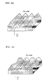
- FIG. 10A illustrates a prism sheet according to an embodiment of the present invention in x-direction
- FIG. 10B illustrates a prism sheet according to an embodiment of the present invention in y-direction.
- FIG. 6A illustrates a transmission prism lattice to explain diffraction of light at the prism lattice that is a theory background for structure of the prism sheet according to an embodiment of the present invention.
- FIG. 6B illustrates relation between lattice constant and the lattice to explain diffraction of light at the prism lattice that is a theory background for structure of the prism sheet according to an embodiment of the present invention.
- FIG. 7A illustrates a general prism lattice sheet to compare diffraction properties of prism sheets that have a center of structural surface.
- FIG. 7B illustrates a prism lattice sheet according to the present invention to compare diffraction properties of prism sheets that have a center of structural surface.
- FIG. 6A illustrates a transmission prism lattice to explain diffraction of light at the prism lattice that is a theory background for structure of the prism sheet according to an embodiment of the present invention.
- FIG. 6B illustrate
- FIG. 8A is a reference diagram illustrating arrangement and illumination of prism lattice sheets having a predetermined lattice to compare illuminations in lattice structure of the prism sheets that have a center of structural surface.
- FIG. 8B is a reference diagram illustrating arrangement and illumination of prism lattice sheets having a predetermined lattice changing periodically to compare illuminations in lattice structure of the prism sheets that have a center of structural surface.
- FIG. 9 illustrates phase difference according to a structural surface and change of thickness of a prism sheet.
- FIG. 10A illustrates a prism sheet according to an embodiment of the present invention in x-direction.
- FIG. 10B illustrates a prism sheet according to an embodiment of the present invention in y-direction.
- the prism sheet according to an embodiment of the present invention has a structural surface 14 on one side thereof and a flat surface 15 opposing the structural surface on another side thereof.
- the structural surface 14 includes a linear arrangement of right-angled isosceles triangular prisms arranged in parallel and configured to form a plurality of peaks 11 and valleys 12 , each of the prisms having perpendicular surfaces that slant by an angle of approximately 45° with respect to the flat surface 15 .
- the structural surface 14 is configured to have non-planar peaks 11 with a maximum height and a minimum height along a length direction of the peak.
- a curved layer 17 having the same cycle as a cycle of height variation of the peak is formed at a boundary surface 16 between the structural surface 14 and the flat surface so as to maintain the right-angled isosceles triangular prisms formed due to a difference between the highest point and the lowest point of each of the peaks to have a predetermined size so that a distance between the valleys 12 is uniform along the length direction.
- the peak 11 is shaped in a streamline curvature 18 in which a difference between the maximum height to the minimum height is shown in a fluent curvature.
- the streamline curvature formed due to the difference between heights of the peaks has a cycle, which is repeated periodically or non-periodically.
- the prism sheet is made of transparent and flexible polymer film.
- the polymer film can be made of any one polymer selected from the group consisting of acrylate, polycarbonate, polyester, and polyvinyl chloride.
- the polymer film can be either a multi-layer film in which acrylate is laminated on polycarbonate or a multi-layer film in which acrylate is laminated on polyester.
- the prism sheet is constructed such that at least two prisms are arranged every unit pixel for the LCD, i.e., the prism has a size of 0.127 mm or less so that the condensing function of the prism can be constantly exhibited for each of LCD pixels without a complicated alignment of the prism sheet with the LCD panel.
- the peak has the height variation h of the range of 0.125-2.5 ⁇ m in which constructive interference and destructive interference are not caused in visible light range so as to minimize moire phenomenon.
- a backlight unit according to an embodiment of the present invention, employing such prism sheets 10 includes at least one prism sheet including non-planar peaks 11 and a curved layer 17 .
- the non-planar peaks 11 have a maximum height and a minimum height distinguished along a length direction.
- the curved layer 17 having the same cycle as a cycle of height variation of the peak is formed at a boundary surface 16 between the structural surface 14 and the flat surface so as to maintain the right-angled isosceles triangular prisms formed due to a difference between the highest point and the lowest point of the peak to have a predetermined size, so that a distance between the valleys 12 is uniform along the length direction.
- the theoretical background of the structure of the prism sheet according to the embodiment of the present invention will be described referring to FIGS. 6 to 9 .
- the basic theory starts from the diffraction lattice theory.
- Diffraction lattice is meant by an apparatus in which the diffraction holes or obstacles are arranged periodically to generate a periodic variation in the phase and/or the amplitude of an emitting wave.
- the diffraction lattice is devised by David Rittenhouse who is an American astronomer in 1785. A few years later, Joseph von Fraunhofer found this principle again independently and rendered great services to theories and technology on lattice.
- Wave surface that has passed an apparatus in which thin wire or thread is wound between two parallel screws is modulated in amplitude due to an arrangement in which transparent portions and opaque portions are alternatively repeated. Therefore, the multi-slit arrangement is called transmission amplitude lattice, and more general, transmission amplitude lattice is made by scratching or digging parallel grooves on a flat and transparent glass plate.
- each of the formed grooves serves as a scattering light source and the whole grooves forms an arrangement of linear light sources that are parallel with one another and regular.
- a lattice transmits light completely with little amplitude modulation and has an optical thickness regularly varied.
- Such a lattice causes a phase modulates and is called transmission phase lattice.
- the shape of the wave surface instead of amplitude is changed periodically as shown in FIG. 6a and includes continuously distributed plane and components.
- the conventional lattice that has irregular periods minimizes transmission amplitude lattice phenomenon.
- the conventional lattice that uses multi-sheet belongs to the manner that to minimizing transmission phase lattice phenomenon.
- the present invention provides the manner to minimize the diffraction effect using transmission amplitude and phase conditions.
- phase condition can be represented as equation 2.
- AB ⁇ CD ⁇ (sin ⁇ m ⁇ sin ⁇ i ) Equation 2
- FIG. 7A illustrates the lattice structure of a general prism sheet
- FIG. 7B illustrates the lattice structure of a general prism sheet according to the present invention.
- FIGS. 7A and 7B is provided to compare such lattice structures and describe diffraction properties.
- each of the phases of the waves has any value between 0 and 2 ⁇ with the same probability.
- the light wave made of superposition of the N phasors which have the same phase and relative phases.
- phase difference is the most important in diffraction. This is the physical basis of the present invention.
- the incident light group derives the light in the direction perpendicular to the surface of the lattice and changes phase difference so that amplitude variation in traveling direction of the prism lattice is derived without diffraction phenomenon to the eyes of an observer. That the beams group is derived in the direction perpendicular to the lattice surface means that the distribution of the effective index of diffraction is changed due to periodic amplitude variation in the traveling direction. Since the light moves toward the portion whose effective index of diffraction is higher, the direction of the light is changed.
- FIG. 7A illustrates that the light is diffracted since the light is derived in the same direction at one point. It is because the phase same as the phase of a projected wave is developed. However, in this case, since the sum of the phases is not zero at one point because of the above-mentioned physical basis, the interference is reduced. It is because the sum of the phases is not zero.
- FIG. 9 is the transparent front view of a prism sheet.
- phase difference is considered at the thickness.
- the real product shows the variation as much as the thickness ( ⁇ ).
- the above-mentioned amplitude makes not only the difference of the amount of irradiance but also phase difference.
- ⁇ 0 and ⁇ 1 imply the phase path differences of their lattices.
- k is the number of waves
- n is index of diffraction of lattice
- ⁇ is thickness variation.
- the thickness difference makes the difference of ⁇ 0 and ⁇ 1 be non-zero so that diffraction effect is reduced. Even though the light transmits again due to internal reflection, the difference appears the same.
- the principles used in the present invention are the transmission amplitude lattice theory and the phase lattice theory.
- the diffraction efficiency reduction was described by using fluctuation phenomenon at the point of view of the observers caused by deflection of light due to effective index of diffraction and irradiance difference.
- the attenuation of diffraction interference was described using the fact that the thickness variation cannot make the difference of the phase paths be zero based on the phase lattice theory.
- the prism sheet according to the embodiment of the present invention will be described referring to FIG. 10 .
- the structural surface 14 of the prism sheet 10 has non-planar peaks 11 which have distinguished the maximum height and the minimum height along a length direction, as shown in FIGS. 10A and 10B .
- the curved layer 17 is formed to have the same cycle as a cycle of height variation of the peak is formed at the boundary surface 16 between the structural surface 14 and the flat surface so as to maintain the right-angled isosceles triangular prisms formed due to the difference between the highest point and the lowest point to have a predetermined size, so that the distance between the valleys 12 is uniform along the length direction.
- the peak 11 is shaped in the streamline curvature 18 in which a difference between the maximum height to the minimum height is shown in a fluent curvature.
- the streamline curvature formed due to the difference between heights of the peaks has a cycle, which is repeated periodically or non-periodically.
- the prism sheet according to the present invention has the structure in which the height varying along the length direction (y direction) with a predetermined period ( ⁇ ).
- kn ⁇ / ⁇ where ⁇ is wavelength (0.4-0.6 ⁇ m) of visible light.
- ⁇ is wavelength (0.4-0.6 ⁇ m) of visible light.
- the variation ( ⁇ ) of height is about 0.125-0.25 ⁇ m. If the height of the prism is 25 ⁇ m, the height variation is about 0.5-1% of the height of the prism.
- the height variation is about 0.125-2.5 ⁇ m.
- the range in which the diffraction can occur between sheet peak 11 that has a varying height and an adjacent sheet is reduced so that the optical coupling between the sheet peak 11 and the adjacent sheet is reduced.
- the prism sheet structure of the backlight unit according to the present invention as described above reduces the range of the diffraction with the upper sheet and reduces the optical coupling so that the moir 6 pattern is suppressed and the high quality of image can be provided.
Abstract
Description
a sin θm=m λ
AB−CD=α(sin θm−sin θi)
Ψ0−Ψ1 =kn δ
Claims (15)
Applications Claiming Priority (3)
| Application Number | Priority Date | Filing Date | Title |
|---|---|---|---|
| KR10-2003-0044316 | 2003-07-01 | ||
| KR1020030044316A KR100432347B1 (en) | 2003-07-01 | 2003-07-01 | Prism sheet of back light unit for lcd |
| PCT/KR2003/002102 WO2005003851A1 (en) | 2003-07-01 | 2003-10-13 | Prism sheet of back light unit for lcd |
Publications (2)
| Publication Number | Publication Date |
|---|---|
| US20070097708A1 US20070097708A1 (en) | 2007-05-03 |
| US7488095B2 true US7488095B2 (en) | 2009-02-10 |
Family
ID=36785111
Family Applications (1)
| Application Number | Title | Priority Date | Filing Date |
|---|---|---|---|
| US10/562,263 Expired - Lifetime US7488095B2 (en) | 2003-07-01 | 2003-10-13 | Prism sheet of back light unit for LCD |
Country Status (7)
| Country | Link |
|---|---|
| US (1) | US7488095B2 (en) |
| JP (1) | JP2007520723A (en) |
| KR (1) | KR100432347B1 (en) |
| CN (1) | CN100430800C (en) |
| AU (1) | AU2003269523A1 (en) |
| TW (1) | TW200502652A (en) |
| WO (1) | WO2005003851A1 (en) |
Cited By (6)
| Publication number | Priority date | Publication date | Assignee | Title |
|---|---|---|---|---|
| US20090059128A1 (en) * | 2007-09-03 | 2009-03-05 | Young Soo Han | Prism sheet having inclined ridges and liquid crystal display using the same |
| US20090167987A1 (en) * | 2007-12-31 | 2009-07-02 | Heu-Gon Kim | Light Guide Plate, and Backlight Assembly and Liquid Crystal Display Having the Same |
| US20100042669A1 (en) * | 2008-08-14 | 2010-02-18 | Searete Llc, A Limited Liability Corporation Of The State Of Delaware | System and method for modifying illusory user identification characteristics |
| US20100066942A1 (en) * | 2006-11-09 | 2010-03-18 | Daisuke Teragawa | Prism sheet and liquid crystal display |
| US9188729B2 (en) | 2012-10-15 | 2015-11-17 | Samsung Display Co., Ltd. | Prism sheet, backlight unit including the same, and method of manufacturing the same |
| US20220347879A1 (en) * | 2018-09-21 | 2022-11-03 | Dexerials Corporation | Transfer mold |
Families Citing this family (31)
| Publication number | Priority date | Publication date | Assignee | Title |
|---|---|---|---|---|
| WO2006133458A2 (en) | 2005-06-09 | 2006-12-14 | Ubright Optronics Corporation | Moire reducing optical substrates with irregular prism structures |
| US9366875B2 (en) * | 2005-06-09 | 2016-06-14 | Ubright Optronics Corporation | Light directing film |
| KR101132947B1 (en) * | 2005-06-29 | 2012-04-05 | 엘지디스플레이 주식회사 | Backlight unit and liquid crystal display device including the same |
| KR20070008152A (en) | 2005-07-13 | 2007-01-17 | 삼성전자주식회사 | Prism member and a backlight assembly provided with the same and a display device provided with the same |
| US7815355B2 (en) | 2005-08-27 | 2010-10-19 | 3M Innovative Properties Company | Direct-lit backlight having light recycling cavity with concave transflector |
| TW200736754A (en) * | 2006-03-31 | 2007-10-01 | Gamma Optical Co Ltd | Optical film for edge-type backlight module |
| TWI278662B (en) * | 2006-03-31 | 2007-04-11 | Gamma Optical Co Ltd | Optical film structure |
| JP4105736B2 (en) | 2006-04-28 | 2008-06-25 | 日立マクセル株式会社 | Lens sheet, backlight and display device using the same |
| CN100422805C (en) * | 2006-09-25 | 2008-10-01 | 友达光电股份有限公司 | Liquid crystal display board |
| KR100837305B1 (en) * | 2007-03-15 | 2008-06-12 | 엘지전자 주식회사 | Optical sheet, backlight unit and liquid crystal display device using the same |
| KR100936715B1 (en) | 2007-03-16 | 2010-01-13 | 엘지전자 주식회사 | Optical film and Display device having the same |
| CN101363926B (en) * | 2007-08-07 | 2011-11-16 | 鸿富锦精密工业(深圳)有限公司 | LCD device and prismatic lens thereof |
| KR100918033B1 (en) * | 2007-09-05 | 2009-09-18 | 제일모직주식회사 | Prism sheet having wet-out property and LCD back light unit thereby |
| KR20150076260A (en) | 2007-09-21 | 2015-07-06 | 쓰리엠 이노베이티브 프로퍼티즈 컴파니 | Optical film |
| JP5702151B2 (en) * | 2008-02-07 | 2015-04-15 | スリーエム イノベイティブ プロパティズ カンパニー | Hollow backlight with structured film |
| TW200949369A (en) * | 2008-02-15 | 2009-12-01 | 3M Innovative Properties Co | Brightness enhancing film and film based diffuser for improved illumination uniformity of displays |
| KR100817768B1 (en) * | 2008-02-29 | 2008-03-31 | 주식회사 엘지에스 | Optical film, liquid crystal display device having the same |
| KR101609400B1 (en) | 2008-04-02 | 2016-04-05 | 쓰리엠 이노베이티브 프로퍼티즈 컴파니 | Light directing film or light directing article |
| KR101234841B1 (en) | 2008-08-04 | 2013-02-19 | 제일모직주식회사 | Prism sheet having lengthwise wave patterned optical condensing portions and reflection portions, back light unit having the prism sheet and liquid crystal display device having the back light unit |
| CN102590905B (en) * | 2011-01-05 | 2016-05-18 | 迎辉科技股份有限公司 | There is the blooming of height relief fabric |
| FR2973555B1 (en) * | 2011-04-01 | 2014-05-16 | Valeo Systemes Thermiques | CONTROL AND DISPLAY MODULE FOR MOTOR VEHICLE |
| CN102213780A (en) * | 2011-07-13 | 2011-10-12 | 北京康得新复合材料股份有限公司 | Bright enhancement film of prism structure |
| TWI459043B (en) * | 2011-10-04 | 2014-11-01 | Au Optronics Corp | Optical film and backlight module using the same |
| CN103630953B (en) * | 2012-08-22 | 2016-08-03 | 北京京东方光电科技有限公司 | A kind of prism film and preparation method thereof and device |
| JP6119490B2 (en) | 2013-07-31 | 2017-04-26 | ソニー株式会社 | Light source device and display device |
| KR102232693B1 (en) | 2014-10-17 | 2021-03-29 | 삼성디스플레이 주식회사 | Flexible display device |
| CN106226859B (en) * | 2015-06-02 | 2019-09-06 | 友辉光电股份有限公司 | Light directing film |
| CN104991297A (en) * | 2015-07-16 | 2015-10-21 | 宁波东旭成新材料科技有限公司 | Self-repairing brightness enhancement film |
| CN106704847A (en) * | 2016-12-29 | 2017-05-24 | 中山市光大光学仪器有限公司 | Spotlighting device |
| CN107884990B (en) * | 2017-11-30 | 2022-02-22 | 武汉天马微电子有限公司 | Backlight module and display device |
| WO2023019139A1 (en) * | 2021-08-10 | 2023-02-16 | Edmund Optics, Inc. | Optical component for redirecting light |
Citations (6)
| Publication number | Priority date | Publication date | Assignee | Title |
|---|---|---|---|---|
| JPH09160507A (en) | 1995-12-04 | 1997-06-20 | Dainippon Printing Co Ltd | Surface light source device using non-light-diffusive light guide plate, and lens film |
| JP2001004846A (en) | 1999-06-21 | 2001-01-12 | Fujitsu Kasei Kk | Light guide plate |
| JP2001188126A (en) | 2000-01-05 | 2001-07-10 | Fuji Photo Film Co Ltd | Polarized light separating prism sheet and illuminator |
| US6354709B1 (en) * | 1998-02-18 | 2002-03-12 | 3M Innovative Properties Company | Optical film |
| US6692133B2 (en) * | 2000-07-25 | 2004-02-17 | International Business Machines Corporation | Plane light source apparatus, light guide plate and display |
| US20050141243A1 (en) * | 2000-08-18 | 2005-06-30 | Reflexite Corporation | Differentially-cured materials and process for forming same |
Family Cites Families (1)
| Publication number | Priority date | Publication date | Assignee | Title |
|---|---|---|---|---|
| EP1852735A1 (en) * | 2000-12-13 | 2007-11-07 | Mitsubishi Rayon Co. Ltd. | Light source device |
-
2003
- 2003-07-01 KR KR1020030044316A patent/KR100432347B1/en active IP Right Grant
- 2003-10-13 JP JP2005503418A patent/JP2007520723A/en not_active Withdrawn
- 2003-10-13 WO PCT/KR2003/002102 patent/WO2005003851A1/en active Application Filing
- 2003-10-13 CN CNB2003801103607A patent/CN100430800C/en not_active Expired - Lifetime
- 2003-10-13 AU AU2003269523A patent/AU2003269523A1/en not_active Abandoned
- 2003-10-13 US US10/562,263 patent/US7488095B2/en not_active Expired - Lifetime
-
2004
- 2004-06-14 TW TW093117036A patent/TW200502652A/en unknown
Patent Citations (6)
| Publication number | Priority date | Publication date | Assignee | Title |
|---|---|---|---|---|
| JPH09160507A (en) | 1995-12-04 | 1997-06-20 | Dainippon Printing Co Ltd | Surface light source device using non-light-diffusive light guide plate, and lens film |
| US6354709B1 (en) * | 1998-02-18 | 2002-03-12 | 3M Innovative Properties Company | Optical film |
| JP2001004846A (en) | 1999-06-21 | 2001-01-12 | Fujitsu Kasei Kk | Light guide plate |
| JP2001188126A (en) | 2000-01-05 | 2001-07-10 | Fuji Photo Film Co Ltd | Polarized light separating prism sheet and illuminator |
| US6692133B2 (en) * | 2000-07-25 | 2004-02-17 | International Business Machines Corporation | Plane light source apparatus, light guide plate and display |
| US20050141243A1 (en) * | 2000-08-18 | 2005-06-30 | Reflexite Corporation | Differentially-cured materials and process for forming same |
Non-Patent Citations (1)
| Title |
|---|
| International Search Report for PCT/KR2003/002102. |
Cited By (9)
| Publication number | Priority date | Publication date | Assignee | Title |
|---|---|---|---|---|
| US20100066942A1 (en) * | 2006-11-09 | 2010-03-18 | Daisuke Teragawa | Prism sheet and liquid crystal display |
| US8436960B2 (en) * | 2006-11-09 | 2013-05-07 | Sharp Kabushiki Kaisha | Prism sheet and liquid crystal display |
| US20090059128A1 (en) * | 2007-09-03 | 2009-03-05 | Young Soo Han | Prism sheet having inclined ridges and liquid crystal display using the same |
| US7916242B2 (en) * | 2007-09-03 | 2011-03-29 | Cheil Industries, Inc. | Prism sheet having inclined ridges and liquid crystal display using the same |
| US20090167987A1 (en) * | 2007-12-31 | 2009-07-02 | Heu-Gon Kim | Light Guide Plate, and Backlight Assembly and Liquid Crystal Display Having the Same |
| US8164708B2 (en) * | 2007-12-31 | 2012-04-24 | Samsung Electronics Co., Ltd. | Light guide plate, and backlight assembly and liquid crystal display having the same |
| US20100042669A1 (en) * | 2008-08-14 | 2010-02-18 | Searete Llc, A Limited Liability Corporation Of The State Of Delaware | System and method for modifying illusory user identification characteristics |
| US9188729B2 (en) | 2012-10-15 | 2015-11-17 | Samsung Display Co., Ltd. | Prism sheet, backlight unit including the same, and method of manufacturing the same |
| US20220347879A1 (en) * | 2018-09-21 | 2022-11-03 | Dexerials Corporation | Transfer mold |
Also Published As
| Publication number | Publication date |
|---|---|
| TW200502652A (en) | 2005-01-16 |
| AU2003269523A1 (en) | 2005-01-21 |
| KR100432347B1 (en) | 2004-05-20 |
| CN1788231A (en) | 2006-06-14 |
| WO2005003851A1 (en) | 2005-01-13 |
| CN100430800C (en) | 2008-11-05 |
| US20070097708A1 (en) | 2007-05-03 |
| JP2007520723A (en) | 2007-07-26 |
Similar Documents
| Publication | Publication Date | Title |
|---|---|---|
| US7488095B2 (en) | Prism sheet of back light unit for LCD | |
| US8317386B2 (en) | Laser-lit planar illumination device and LCD using such device | |
| US7303323B2 (en) | Backlight assembly of liquid crystal display | |
| US7407317B2 (en) | Prism sheet and backlight unit using the same | |
| KR100764592B1 (en) | backlight for liquid crystal display devices | |
| US7489373B2 (en) | Prism sheet and liquid crystal display having the same | |
| US7645057B2 (en) | Optical sheet and backlight assembly of liquid crystal display with the same | |
| USRE45749E1 (en) | Optical unit, backlight assembly having the same and display device having the same | |
| KR20060066106A (en) | Brightness enhancement article | |
| JP2010055057A (en) | Liquid crystal display apparatus | |
| KR20010036520A (en) | BackLight Unit | |
| US20100085511A1 (en) | Display device | |
| JP2007115451A (en) | Planar light source device | |
| US20050073828A1 (en) | Backlight unit for liquid crystal display | |
| JP2000267096A (en) | Back light device for liquid crystal display | |
| US20070002585A1 (en) | Backlight unit | |
| JP2007053021A (en) | Light guide plate, flat lighting system, and liquid crystal display | |
| KR100845250B1 (en) | The backlight unit | |
| JP2002341118A (en) | Light reflection sheet and method for manufacturing the same and surface light source device and liquid crystal display device both using the light reflection sheet | |
| KR100879950B1 (en) | Edge type backlight unit of using micro triangle lens pattern | |
| JP2001126519A (en) | Sheet light source device and liquid crystal display using the same | |
| KR20120063187A (en) | Optical film, light source assembly including the same and liquid crystal display including the light source assembly | |
| JP2002303733A (en) | Light transmission body, surface light source device using the same and liquid crystal display device | |
| KR20030055844A (en) | Liquid crystal display apparatus | |
| KR20100009010A (en) | A optical sheet and a liquid crystal display device comprising the same |
Legal Events
| Date | Code | Title | Description |
|---|---|---|---|
| AS | Assignment |
Owner name: LGS CORPORATION, KOREA, REPUBLIC OF Free format text: ASSIGNMENT OF ASSIGNORS INTEREST;ASSIGNORS:SHIM, YOUNG-SHIG;CHO, SUNG-MIN;PARK, SOON-RYONG;AND OTHERS;REEL/FRAME:017408/0173 Effective date: 20051219 |
|
| AS | Assignment |
Owner name: LMS CO., LTD., KOREA, REPUBLIC OF Free format text: CHANGE OF NAME;ASSIGNOR:LGS CORPORATION;REEL/FRAME:022050/0640 Effective date: 20080725 |
|
| STCF | Information on status: patent grant |
Free format text: PATENTED CASE |
|
| FPAY | Fee payment |
Year of fee payment: 4 |
|
| FPAY | Fee payment |
Year of fee payment: 8 |
|
| AS | Assignment |
Owner name: LMS (SUZHOU) MATERIALS CO., LTD., CHINA Free format text: ASSIGNMENT OF ASSIGNORS INTEREST;ASSIGNOR:LMS CO., LTD.;REEL/FRAME:047311/0020 Effective date: 20181025 |
|
| MAFP | Maintenance fee payment |
Free format text: PAYMENT OF MAINTENANCE FEE, 12TH YR, SMALL ENTITY (ORIGINAL EVENT CODE: M2553); ENTITY STATUS OF PATENT OWNER: SMALL ENTITY Year of fee payment: 12 |