US7489843B2 - Polyurethane to polyethylene adhesion process - Google Patents
Polyurethane to polyethylene adhesion process Download PDFInfo
- Publication number
- US7489843B2 US7489843B2 US11/702,914 US70291407A US7489843B2 US 7489843 B2 US7489843 B2 US 7489843B2 US 70291407 A US70291407 A US 70291407A US 7489843 B2 US7489843 B2 US 7489843B2
- Authority
- US
- United States
- Prior art keywords
- area
- cable
- enclosure
- cleaning
- distribution cable
- Prior art date
- Legal status (The legal status is an assumption and is not a legal conclusion. Google has not performed a legal analysis and makes no representation as to the accuracy of the status listed.)
- Expired - Fee Related
Links
Images


Classifications
-
- G—PHYSICS
- G02—OPTICS
- G02B—OPTICAL ELEMENTS, SYSTEMS OR APPARATUS
- G02B6/00—Light guides; Structural details of arrangements comprising light guides and other optical elements, e.g. couplings
- G02B6/44—Mechanical structures for providing tensile strength and external protection for fibres, e.g. optical transmission cables
- G02B6/4439—Auxiliary devices
- G02B6/4471—Terminating devices ; Cable clamps
- G02B6/4472—Manifolds
- G02B6/4475—Manifolds with provision for lateral branching
-
- B—PERFORMING OPERATIONS; TRANSPORTING
- B29—WORKING OF PLASTICS; WORKING OF SUBSTANCES IN A PLASTIC STATE IN GENERAL
- B29C—SHAPING OR JOINING OF PLASTICS; SHAPING OF MATERIAL IN A PLASTIC STATE, NOT OTHERWISE PROVIDED FOR; AFTER-TREATMENT OF THE SHAPED PRODUCTS, e.g. REPAIRING
- B29C45/00—Injection moulding, i.e. forcing the required volume of moulding material through a nozzle into a closed mould; Apparatus therefor
- B29C45/14—Injection moulding, i.e. forcing the required volume of moulding material through a nozzle into a closed mould; Apparatus therefor incorporating preformed parts or layers, e.g. injection moulding around inserts or for coating articles
- B29C45/14549—Coating rod-like, wire-like or belt-like articles
-
- B—PERFORMING OPERATIONS; TRANSPORTING
- B29—WORKING OF PLASTICS; WORKING OF SUBSTANCES IN A PLASTIC STATE IN GENERAL
- B29C—SHAPING OR JOINING OF PLASTICS; SHAPING OF MATERIAL IN A PLASTIC STATE, NOT OTHERWISE PROVIDED FOR; AFTER-TREATMENT OF THE SHAPED PRODUCTS, e.g. REPAIRING
- B29C65/00—Joining or sealing of preformed parts, e.g. welding of plastics materials; Apparatus therefor
- B29C65/70—Joining or sealing of preformed parts, e.g. welding of plastics materials; Apparatus therefor by moulding
-
- B—PERFORMING OPERATIONS; TRANSPORTING
- B29—WORKING OF PLASTICS; WORKING OF SUBSTANCES IN A PLASTIC STATE IN GENERAL
- B29C—SHAPING OR JOINING OF PLASTICS; SHAPING OF MATERIAL IN A PLASTIC STATE, NOT OTHERWISE PROVIDED FOR; AFTER-TREATMENT OF THE SHAPED PRODUCTS, e.g. REPAIRING
- B29C66/00—General aspects of processes or apparatus for joining preformed parts
- B29C66/01—General aspects dealing with the joint area or with the area to be joined
- B29C66/02—Preparation of the material, in the area to be joined, prior to joining or welding
- B29C66/022—Mechanical pre-treatments, e.g. reshaping
- B29C66/0224—Mechanical pre-treatments, e.g. reshaping with removal of material
- B29C66/02245—Abrading, e.g. grinding, sanding, sandblasting or scraping
-
- B—PERFORMING OPERATIONS; TRANSPORTING
- B29—WORKING OF PLASTICS; WORKING OF SUBSTANCES IN A PLASTIC STATE IN GENERAL
- B29C—SHAPING OR JOINING OF PLASTICS; SHAPING OF MATERIAL IN A PLASTIC STATE, NOT OTHERWISE PROVIDED FOR; AFTER-TREATMENT OF THE SHAPED PRODUCTS, e.g. REPAIRING
- B29C66/00—General aspects of processes or apparatus for joining preformed parts
- B29C66/01—General aspects dealing with the joint area or with the area to be joined
- B29C66/02—Preparation of the material, in the area to be joined, prior to joining or welding
- B29C66/026—Chemical pre-treatments
-
- B—PERFORMING OPERATIONS; TRANSPORTING
- B29—WORKING OF PLASTICS; WORKING OF SUBSTANCES IN A PLASTIC STATE IN GENERAL
- B29C—SHAPING OR JOINING OF PLASTICS; SHAPING OF MATERIAL IN A PLASTIC STATE, NOT OTHERWISE PROVIDED FOR; AFTER-TREATMENT OF THE SHAPED PRODUCTS, e.g. REPAIRING
- B29C66/00—General aspects of processes or apparatus for joining preformed parts
- B29C66/01—General aspects dealing with the joint area or with the area to be joined
- B29C66/02—Preparation of the material, in the area to be joined, prior to joining or welding
- B29C66/028—Non-mechanical surface pre-treatments, i.e. by flame treatment, electric discharge treatment, plasma treatment, wave energy or particle radiation
-
- B—PERFORMING OPERATIONS; TRANSPORTING
- B29—WORKING OF PLASTICS; WORKING OF SUBSTANCES IN A PLASTIC STATE IN GENERAL
- B29C—SHAPING OR JOINING OF PLASTICS; SHAPING OF MATERIAL IN A PLASTIC STATE, NOT OTHERWISE PROVIDED FOR; AFTER-TREATMENT OF THE SHAPED PRODUCTS, e.g. REPAIRING
- B29C66/00—General aspects of processes or apparatus for joining preformed parts
- B29C66/50—General aspects of joining tubular articles; General aspects of joining long products, i.e. bars or profiled elements; General aspects of joining single elements to tubular articles, hollow articles or bars; General aspects of joining several hollow-preforms to form hollow or tubular articles
- B29C66/51—Joining tubular articles, profiled elements or bars; Joining single elements to tubular articles, hollow articles or bars; Joining several hollow-preforms to form hollow or tubular articles
- B29C66/52—Joining tubular articles, bars or profiled elements
- B29C66/526—Joining bars
-
- B—PERFORMING OPERATIONS; TRANSPORTING
- B29—WORKING OF PLASTICS; WORKING OF SUBSTANCES IN A PLASTIC STATE IN GENERAL
- B29C—SHAPING OR JOINING OF PLASTICS; SHAPING OF MATERIAL IN A PLASTIC STATE, NOT OTHERWISE PROVIDED FOR; AFTER-TREATMENT OF THE SHAPED PRODUCTS, e.g. REPAIRING
- B29C66/00—General aspects of processes or apparatus for joining preformed parts
- B29C66/70—General aspects of processes or apparatus for joining preformed parts characterised by the composition, physical properties or the structure of the material of the parts to be joined; Joining with non-plastics material
- B29C66/73—General aspects of processes or apparatus for joining preformed parts characterised by the composition, physical properties or the structure of the material of the parts to be joined; Joining with non-plastics material characterised by the intensive physical properties of the material of the parts to be joined, by the optical properties of the material of the parts to be joined, by the extensive physical properties of the parts to be joined, by the state of the material of the parts to be joined or by the material of the parts to be joined being a thermoplastic or a thermoset
- B29C66/731—General aspects of processes or apparatus for joining preformed parts characterised by the composition, physical properties or the structure of the material of the parts to be joined; Joining with non-plastics material characterised by the intensive physical properties of the material of the parts to be joined, by the optical properties of the material of the parts to be joined, by the extensive physical properties of the parts to be joined, by the state of the material of the parts to be joined or by the material of the parts to be joined being a thermoplastic or a thermoset characterised by the intensive physical properties of the material of the parts to be joined
- B29C66/7316—Surface properties
- B29C66/73161—Roughness or rugosity
-
- C—CHEMISTRY; METALLURGY
- C08—ORGANIC MACROMOLECULAR COMPOUNDS; THEIR PREPARATION OR CHEMICAL WORKING-UP; COMPOSITIONS BASED THEREON
- C08J—WORKING-UP; GENERAL PROCESSES OF COMPOUNDING; AFTER-TREATMENT NOT COVERED BY SUBCLASSES C08B, C08C, C08F, C08G or C08H
- C08J5/00—Manufacture of articles or shaped materials containing macromolecular substances
- C08J5/12—Bonding of a preformed macromolecular material to the same or other solid material such as metal, glass, leather, e.g. using adhesives
- C08J5/121—Bonding of a preformed macromolecular material to the same or other solid material such as metal, glass, leather, e.g. using adhesives by heating
-
- B—PERFORMING OPERATIONS; TRANSPORTING
- B29—WORKING OF PLASTICS; WORKING OF SUBSTANCES IN A PLASTIC STATE IN GENERAL
- B29C—SHAPING OR JOINING OF PLASTICS; SHAPING OF MATERIAL IN A PLASTIC STATE, NOT OTHERWISE PROVIDED FOR; AFTER-TREATMENT OF THE SHAPED PRODUCTS, e.g. REPAIRING
- B29C45/00—Injection moulding, i.e. forcing the required volume of moulding material through a nozzle into a closed mould; Apparatus therefor
- B29C45/14—Injection moulding, i.e. forcing the required volume of moulding material through a nozzle into a closed mould; Apparatus therefor incorporating preformed parts or layers, e.g. injection moulding around inserts or for coating articles
- B29C45/14549—Coating rod-like, wire-like or belt-like articles
- B29C2045/14557—Coating rod-like, wire-like or belt-like articles coating spliced fibres or cables, e.g. optical fiber splices or junctions
-
- B—PERFORMING OPERATIONS; TRANSPORTING
- B29—WORKING OF PLASTICS; WORKING OF SUBSTANCES IN A PLASTIC STATE IN GENERAL
- B29C—SHAPING OR JOINING OF PLASTICS; SHAPING OF MATERIAL IN A PLASTIC STATE, NOT OTHERWISE PROVIDED FOR; AFTER-TREATMENT OF THE SHAPED PRODUCTS, e.g. REPAIRING
- B29C59/00—Surface shaping of articles, e.g. embossing; Apparatus therefor
- B29C59/02—Surface shaping of articles, e.g. embossing; Apparatus therefor by mechanical means, e.g. pressing
- B29C59/04—Surface shaping of articles, e.g. embossing; Apparatus therefor by mechanical means, e.g. pressing using rollers or endless belts
- B29C59/043—Surface shaping of articles, e.g. embossing; Apparatus therefor by mechanical means, e.g. pressing using rollers or endless belts for profiled articles
-
- B—PERFORMING OPERATIONS; TRANSPORTING
- B29—WORKING OF PLASTICS; WORKING OF SUBSTANCES IN A PLASTIC STATE IN GENERAL
- B29C—SHAPING OR JOINING OF PLASTICS; SHAPING OF MATERIAL IN A PLASTIC STATE, NOT OTHERWISE PROVIDED FOR; AFTER-TREATMENT OF THE SHAPED PRODUCTS, e.g. REPAIRING
- B29C66/00—General aspects of processes or apparatus for joining preformed parts
- B29C66/01—General aspects dealing with the joint area or with the area to be joined
- B29C66/02—Preparation of the material, in the area to be joined, prior to joining or welding
- B29C66/022—Mechanical pre-treatments, e.g. reshaping
- B29C66/0222—Mechanical pre-treatments, e.g. reshaping without removal of material, e.g. cleaning by air blowing or using brushes
-
- B—PERFORMING OPERATIONS; TRANSPORTING
- B29—WORKING OF PLASTICS; WORKING OF SUBSTANCES IN A PLASTIC STATE IN GENERAL
- B29C—SHAPING OR JOINING OF PLASTICS; SHAPING OF MATERIAL IN A PLASTIC STATE, NOT OTHERWISE PROVIDED FOR; AFTER-TREATMENT OF THE SHAPED PRODUCTS, e.g. REPAIRING
- B29C66/00—General aspects of processes or apparatus for joining preformed parts
- B29C66/01—General aspects dealing with the joint area or with the area to be joined
- B29C66/05—Particular design of joint configurations
- B29C66/10—Particular design of joint configurations particular design of the joint cross-sections
- B29C66/11—Joint cross-sections comprising a single joint-segment, i.e. one of the parts to be joined comprising a single joint-segment in the joint cross-section
- B29C66/114—Single butt joints
- B29C66/1142—Single butt to butt joints
-
- B—PERFORMING OPERATIONS; TRANSPORTING
- B29—WORKING OF PLASTICS; WORKING OF SUBSTANCES IN A PLASTIC STATE IN GENERAL
- B29C—SHAPING OR JOINING OF PLASTICS; SHAPING OF MATERIAL IN A PLASTIC STATE, NOT OTHERWISE PROVIDED FOR; AFTER-TREATMENT OF THE SHAPED PRODUCTS, e.g. REPAIRING
- B29C66/00—General aspects of processes or apparatus for joining preformed parts
- B29C66/70—General aspects of processes or apparatus for joining preformed parts characterised by the composition, physical properties or the structure of the material of the parts to be joined; Joining with non-plastics material
- B29C66/71—General aspects of processes or apparatus for joining preformed parts characterised by the composition, physical properties or the structure of the material of the parts to be joined; Joining with non-plastics material characterised by the composition of the plastics material of the parts to be joined
-
- B—PERFORMING OPERATIONS; TRANSPORTING
- B29—WORKING OF PLASTICS; WORKING OF SUBSTANCES IN A PLASTIC STATE IN GENERAL
- B29K—INDEXING SCHEME ASSOCIATED WITH SUBCLASSES B29B, B29C OR B29D, RELATING TO MOULDING MATERIALS OR TO MATERIALS FOR MOULDS, REINFORCEMENTS, FILLERS OR PREFORMED PARTS, e.g. INSERTS
- B29K2023/00—Use of polyalkenes or derivatives thereof as moulding material
- B29K2023/04—Polymers of ethylene
- B29K2023/06—PE, i.e. polyethylene
-
- B—PERFORMING OPERATIONS; TRANSPORTING
- B29—WORKING OF PLASTICS; WORKING OF SUBSTANCES IN A PLASTIC STATE IN GENERAL
- B29K—INDEXING SCHEME ASSOCIATED WITH SUBCLASSES B29B, B29C OR B29D, RELATING TO MOULDING MATERIALS OR TO MATERIALS FOR MOULDS, REINFORCEMENTS, FILLERS OR PREFORMED PARTS, e.g. INSERTS
- B29K2075/00—Use of PU, i.e. polyureas or polyurethanes or derivatives thereof, as moulding material
-
- B—PERFORMING OPERATIONS; TRANSPORTING
- B29—WORKING OF PLASTICS; WORKING OF SUBSTANCES IN A PLASTIC STATE IN GENERAL
- B29L—INDEXING SCHEME ASSOCIATED WITH SUBCLASS B29C, RELATING TO PARTICULAR ARTICLES
- B29L2031/00—Other particular articles
- B29L2031/34—Electrical apparatus, e.g. sparking plugs or parts thereof
- B29L2031/3462—Cables
-
- C—CHEMISTRY; METALLURGY
- C08—ORGANIC MACROMOLECULAR COMPOUNDS; THEIR PREPARATION OR CHEMICAL WORKING-UP; COMPOSITIONS BASED THEREON
- C08J—WORKING-UP; GENERAL PROCESSES OF COMPOUNDING; AFTER-TREATMENT NOT COVERED BY SUBCLASSES C08B, C08C, C08F, C08G or C08H
- C08J2323/00—Characterised by the use of homopolymers or copolymers of unsaturated aliphatic hydrocarbons having only one carbon-to-carbon double bond; Derivatives of such polymers
- C08J2323/02—Characterised by the use of homopolymers or copolymers of unsaturated aliphatic hydrocarbons having only one carbon-to-carbon double bond; Derivatives of such polymers not modified by chemical after treatment
- C08J2323/04—Homopolymers or copolymers of ethene
- C08J2323/06—Polyethene
-
- C—CHEMISTRY; METALLURGY
- C08—ORGANIC MACROMOLECULAR COMPOUNDS; THEIR PREPARATION OR CHEMICAL WORKING-UP; COMPOSITIONS BASED THEREON
- C08J—WORKING-UP; GENERAL PROCESSES OF COMPOUNDING; AFTER-TREATMENT NOT COVERED BY SUBCLASSES C08B, C08C, C08F, C08G or C08H
- C08J2375/00—Characterised by the use of polyureas or polyurethanes; Derivatives of such polymers
- C08J2375/04—Polyurethanes
Definitions
- the principles disclosed herein relate to fiber optic cable systems. More particularly, the present disclosure relates to fiber optic cable systems having breakout arrangements protecting branch cables broken out from main cables.
- Passive optical networks are becoming prevalent in part because service providers want to deliver high bandwidth communication capabilities to customers. Passive optical networks are a desirable choice for delivering high-speed communication data because they may not employ active electronic devices, such as amplifiers and repeaters, between a central office and a subscriber termination. The absence of active electronic devices may decrease network complexity and/or cost and may increase network reliability.
- FIG. 1 illustrates a network 100 deploying passive fiber optic lines.
- the network 100 may include a central office 110 that connects a number of end subscribers 115 (also called end users 115 herein) in a network.
- the central office 110 may additionally connect to a larger network such as the Internet (not shown) and a public switched telephone network (PSTN).
- PSTN public switched telephone network
- the network 100 may also include fiber distribution hubs (FDHs) 130 having one or more optical splitters (e.g., 1-to-8 splitters, 1-to-16 splitters, or 1-to-32 splitters) that generate a number of individual fibers that may lead to the premises of an end user 115 .
- the various lines of the network can be aerial or housed within underground conduits (e.g., see conduit 105 ).
- the portion of network 100 that is closest to central office 110 is generally referred to as the F 1 region, where F 1 is the “feeder fiber” from the central office.
- the F 1 portion of the network may include a distribution cable having on the order of 12 to 48 fibers; however, alternative implementations may include fewer or more fibers.
- the portion of network 100 that includes an FDH 130 and a number of end users 115 may be referred to as an F 2 portion of network 100 .
- Splitters used in an FDH 130 may accept a feeder cable having a number of fibers and may split those incoming fibers into, for example, 216 to 432 individual distribution fibers that may be associated with a like number of end user locations.
- the network 100 includes a plurality of breakout locations 125 at which branch cables (e.g., drop cables, stub cables, etc.) are separated out from main cables (e.g., distribution cables).
- Breakout locations can also be referred to as tap locations or branch locations and branch cables can also be referred to as breakout cables.
- fibers of the branch cables are typically spliced to selected fibers of the main cable.
- the interface between the fibers of the main cable and the fibers of the branch cables can be connectorized.
- Stub cables are typically branch cables that are routed from breakout locations to intermediate access locations such as a pedestals, drop terminals or hubs. Intermediate access locations can provide connector interfaces located between breakout locations and subscriber locations.
- a drop cable is a cable that typically forms the last leg to a subscriber location. For example, drop cables are routed from intermediate access locations to subscriber locations. Drop cables can also be routed directly from breakout locations to subscriber locations hereby bypassing any intermediate access locations
- Branch cables can manually be separated out from a main cable in the field using field splices.
- Field splices are typically housed within sealed splice enclosures. Manual splicing in the field is time consuming and expensive.
- Pre-terminated cable systems include factory integrated breakout locations manufactured at predetermined positions along the length of a main cable (e.g., see U.S. Pat. Nos. 4,961,623; 5,125,060; and 5,210,812).
- pre-terminated cables can be difficult.
- pre-terminations can complicate passing pre-terminated cable through the underground conduit typically used to hold fiber optic cable (e.g., 1.25 inch inner diameter conduit).
- fiber optic cable e.g., 1.25 inch inner diameter conduit
- aerial applications pre-terminations can complicate passing pre-terminated cable through aerial cable retention loops.
- Certain aspects of the disclosure relate to a breakout process for pre-terminating branch cables to fiber optic distribution cables.
- inventive aspects can relate to individual features and to combinations of features. It is to be understood that both the forgoing general description and the following detailed description are exemplary and explanatory only and are not restrictive of the broad inventive concepts upon which the embodiments disclosed herein are based.
- FIG. 1 shows a prior art passive fiber optic network
- FIG. 2 is a side view of a tether branching from a distribution cable
- FIG. 3 is a cross sectional view of an example distribution cable
- FIG. 4 is a cross sectional view of an example tether
- FIG. 5 is a perspective view of an example breakout assembly installed on a distribution cable at breakout location
- FIG. 6 is a perspective view of an example retention block used at the breakout location of FIG. 5 ;
- FIG. 7 shows an initial preparation of the distribution cable at the breakout location of FIG. 5 ;
- FIG. 8 shows a first preparation step for a tether used at the breakout location of FIG. 5 ;
- FIG. 9 shows a subsequent preparation step for the tether of FIG. 8 ;
- FIG. 10 is a side view of an enclosure installed at breakout location according to one embodiment of the present disclosure.
- FIG. 11 is a top view of the enclosure of FIG. 10 ;
- FIG. 12 is a flowchart illustrating an example installation process for installing an enclosure over a breakout assembly according to one embodiment of the present disclosure
- FIG. 13 is a schematic view of a telecommunications cable including a tether branching from a distribution cable.
- FIG. 14 is a flowchart illustrating an example treatment process for preparing a cable to bond with an enclosure body according to one embodiment of the present disclosure.
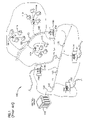
- FIG. 15 is a schematic diagram showing respective movement of a cable relative to a plasma etcher during the treatment process of FIG. 14 ;
- FIG. 16 is a flow chart illustrating an example overmolding process for forming the enclosure body according to one embodiment of the present disclosure
- FIG. 17 is a cross-sectional, schematic view depicting a distribution cable and tether placed within molds during the overmolding process of FIG. 16 ;
- FIG. 18 is a schematic diagram depicting an enclosure overmolded over a breakout location on a distribution cable of FIG. 17 .
- the present disclosure relates to mid-span breakout arrangements provided on distribution cables and methods for providing the breakout arrangements.
- Each breakout arrangement is provided at a breakout location to protect the optical coupling of a tether (i.e., a branch cable) to a distribution cable.
- a tether i.e., a branch cable
- a typical breakout location 260 is provided at an intermediate point along the length of a distribution cable 220 (e.g., see FIG. 2 ).
- a fiber 224 t of a tether 240 is optically coupled to a fiber 224 dc of the distribution cable 220 at a coupling location 205 .
- An enclosure 300 e.g., an overmold
- FIG. 3 shows an example distribution cable 220 including six separate buffer tubes 222 each containing twelve fibers 224 dc .
- the buffer tubes 222 may be gel filled.
- the distribution cable 220 also includes a central strength member 226 for reinforcing the cable 220 , and an outer strength layer/member 228 , such as aramid fiber/yarn (e.g., Kevlar® fiber), also for reinforcing the cable.
- the distribution cable 220 further includes an outer jacket 230 that encloses the buffer tubes 222 . Ripcords 232 can be provided for facilitating tearing away portions of the jacket 230 to access the fibers 224 dc within the jacket 230 .
- a typical distribution cable includes a relatively large number of fibers (e.g., 72, 144 or more fibers).
- the fibers are typically segregated into separate groups with each group contained within a separate buffer tube.
- the fibers within each buffer tube can include either ribbon fibers or loose fibers.
- the distribution cable can include an outer jacket enclosing a single buffer tube and at least two strength members extending on opposite sides of the single buffer tube (not shown).
- An outer strength layer/member such as aramid fiber/yarn, can surround the single buffer tube within the jacket.
- the single buffer tube can enclose loose fibers or ribbon fibers.
- FIG. 4 illustrates an example tether 240 configured to join to the distribution cable 220 at the breakout location 260 .
- the tether 240 includes a central buffer tube 242 containing multiple fibers 224 t (e.g., typically one to twelve loose or ribbonized fibers).
- Strength members 246 e.g., flexible rods formed by glass fiber reinforced epoxy
- An outer jacket 250 surrounds the strength members 246 and the buffer tube 242 .
- An additional strength layer 248 e.g., aramid fiber/yarn
- the tether 240 is depicted as having a flat cable configuration.
- the outer jacket 250 includes an outer perimeter having an elongated transverse cross-sectional shape.
- the transverse cross-sectional shape includes oppositely positioned, generally parallel sides 252 interconnected by rounded ends 254 .
- any suitable cable configuration can be utilized for both the distribution cable and the tether cable.
- one or more tether fibers (e.g., typically less than twelve fibers) 224 t are preferably optically coupled (e.g., spliced) at a coupling location 205 to selected fibers 224 dc of the distribution cable 220 extending from one of the exposed buffer tubes 222 .
- tether fibers 224 t are configured to optically couple to a drop terminal or other type of telecommunications equipment (not shown) offset from the breakout location 260 .
- the tether 240 can terminate in one or more fiber optic connectors (not shown).
- a breakout assembly 200 having features that are examples of inventive aspects in accordance with the principles of the present disclosure is shown installed on a distribution cable in FIG. 5 .
- the breakout assembly 200 includes a sleeve 202 mounted over the optical fibers 224 t , 224 dc at the coupling location 205 .
- An optional protective tube 280 can also be provided over the fibers 224 t , 224 dc and the sleeve 202 .
- An enclosure 300 surrounds the coupled optical fibers 224 dc , 224 t , the sleeve 202 , the optional tube 280 , and the exposed buffer tubes 222 of the distribution cable 220 .
- the enclosure 300 has a body 310 that protects the optical connection between the tether 240 and the distribution cable 220 .
- One end 302 of a body 310 of the enclosure 300 extends over the distribution cable 220 adjacent a first end 352 of the stripped region 350 and the other end 304 of the body 310 extends over the tether cable 240 and the distribution cable 220 adjacent a second end 354 of the stripped region 350 .
- the tether 240 generally extends outwardly a length from the enclosure 300 to a connection end 256 .
- the enclosure 300 can include an overmold.
- the breakout assembly 200 When the tether 240 is secured to the distribution cable 220 , the tether 240 should preferably be able to withstand a pullout force of at least one hundred pounds. To meet this pullout force requirement, the breakout assembly 200 also can includes a retention block 270 (see FIG. 6 ) configured to strengthen the mechanical interface between the tether 240 and the distribution cable 220 . Typically, the retention block 270 is enclosed within the protective enclosure 300 .
- the retention block 270 includes a base 274 and a cover 272 between which the fiber 224 t of the tether 240 extends. First and second protrusions 276 , 278 extend from the cover 272 and base 274 , respectively.
- the retention block 270 has a polycarbonate construction. Further details regarding the retention block 270 can be found in U.S. provisional application Ser. No. 60/781,280, filed Mar. 9, 2006, and entitled “FIBER OPTIC CABLE BREAKOUT CONFIGURATION,” the disclosure of which is hereby incorporated by reference.
- the fibers 224 t of the tether pre-terminated to the fibers 224 dc of the distribution cable. “Pre-terminated” means that the tether fibers 224 t are fused or otherwise connected to the fibers 224 dc of the distribution cable 220 at the factory as part of the cable manufacturing process rather than being field terminated. The remainder of the breakout assembly 200 is also preferably factory installed.
- a portion of the outer jacket 230 is first stripped away to provide a stripped region 350 ( FIG. 7 ).
- portions of a cable netting can be removed adjacent the first and second ends 352 , 354 , respectively, so that the buffer tubes 222 are exposed ( FIG. 7 ).
- the outer strength layer/member 228 also can be displaced (e.g., bunched at one side of the cable 220 ) adjacent the ends 352 , 354 to facilitate accessing the buffer tubes 222 (see, e.g., FIG. 5 ).
- Tape can be used to prevent the intermediate length of netting that remains at the breakout location 260 from unraveling ( FIG. 7 ).
- One of the buffer tubes 222 is selected and a first window 358 is cut into the selected buffer tube 222 adjacent the first end 352 of the stripped region 350 and a second window 360 is cut into the selected buffer tube 222 adjacent the second end 354 of the stripped region 350 ( FIG. 7 ).
- the fibers 224 dc desired to be broken out are accessed and severed at the second window 360 .
- the fibers 224 dc are pulled from the buffer tube 222 through the first window 358 .
- the fibers 224 dc are ready to be terminated to one or more fibers 224 t of a prepared tether 240 .
- a portion of the outer jacket 250 is stripped away to expose the central buffer tube 242 and the strength members 246 (see FIG. 8 ). As shown at FIG. 8 , the central buffer tube 242 and the strength members 246 project outwardly beyond an end 247 of the outer jacket 250 .
- the strength layer 248 ( FIG. 4 ) is removed from around the buffer tube 242 . After removing the end portion of the outer jacket 250 , the strength members 246 are trimmed as shown at FIG. 8 , and an end portion of the central buffer tube 242 is removed to expose the fibers 224 t ( FIG. 9 ).
- the sleeve 202 ( FIG. 5 ) is first slid over the fibers 224 t of the tether.
- the sleeve 202 can be slid up over the buffer tube 242 of the tether 240 .
- the optional protective tube 280 ( FIG. 5 ) also can be slid over the tether 240 .
- the fibers 224 t of the tether 240 are coupled (e.g., fused) to the fibers 224 dc of the distribution cable 220 .
- the sleeve 202 can be slid over the coupling location 205 to protect the fused fibers 224 t , 224 dc .
- the tube 280 can be slid over the sleeve 202 .
- the fibers are then tested to confirm that the fibers meet minimum insertion loss requirements.
- the tether 240 can be mounted to the retention block 270 .
- the strength members 246 can be positioned within side grooves 273 on the base 274 of the retention block 270 , and the central buffer tube 242 can be inserted within a central groove 275 on the base 274 .
- the central buffer tube 242 has a length that extends beyond a first end of the base 274 , and the strength members 246 have lengths that terminate generally at the first end of the base 274 .
- one end of the optional protective tube 280 can be mounted over the protrusions 276 , 278 of the retention block 270 (see FIG. 5 ).
- heat resistant tape is wrapped around the distribution cable 220 , the tether 240 , and the breakout location assembly 200 .
- the enclosure 300 is applied over the taped breakout location 260 (see FIGS. 10-11 ).
- the enclosure (e.g., an overmold layer) 300 seals and protects the underlying components of the breakout assembly 200 .
- the tether 240 extends outwardly from the body 310 of the enclosure 300 to tether connectors (not shown) spaced from the enclosure body 310 .
- FIG. 12 illustrates a flowchart depicting an installation process 1200 for installing the enclosure body 310 .
- the installation process 1200 begins at start module 1202 and proceeds to a first prepare operation 1204 .
- the first prepare operation 1204 provides protection for the exposed buffer tubes 222 and coupled optical fibers 224 dc , 224 t against the heat and other stresses associated with overmolding an enclosure.
- heat resistant tape 208 FIG. 13
- the heat resistant tape 208 is wrapped from the distribution cable jacket 230 adjacent the first end 352 of the stripped region 350 ( FIG. 5 ), around the breakout assembly 200 ( FIG. 5 ), past the second end 354 of the stripped region 350 , and over the distribution cable jacket 230 and tether jacket 250 at the second end 354 of the stripped region 350 ( FIG. 5 ).
- a second prepare operation 1206 provides regions of adhesion on the distribution cable 220 to which the enclosure body 310 can be secured.
- the process for providing the adhesion regions will be discussed herein with reference to FIGS. 14-17 .
- the adhesion regions 322 , 324 are provided on the outer jacket 230 of the distribution cable 220 .
- a first adhesion region 322 is typically provided on the distribution cable 220 adjacent the first end 352 of the stripped region 350 and a second adhesion region 324 is provided adjacent the second end 354 of the stripped region 350 .
- the adhesion regions 322 , 324 have lengths L 1 , L 2 , respectively, that extend longitudinally along the distribution cable 220 ( FIG. 13 ).
- the first adhesion region 322 extends from a first end of the heat resistant tape 208 in a first direction extending generally away from the breakout location 206 ( FIG. 5 ).
- the second adhesion region 324 extends from a second, opposite end of the tape 208 in a second, opposite direction generally away from the breakout location 206 .
- the lengths L 1 , L 2 of the adhesion regions 322 , 324 extend about 1-4 inches, inclusive.
- the lengths L 1 , L 2 each extend about 2-3 inches.
- An optional third prepare operation 1208 provides a region of adhesion on the tether 240 to which the enclosure body 310 also can be secured.
- a third adhesion region 326 having a third length L 3 is shown in FIG. 13 extending over the outer jacket 250 of the tether 240 .
- the third prepare operation 1208 is substantially similar to the second prepare operation 1206 .
- the third adhesion region 326 therefore, is generally similar to the adhesion regions 322 , 324 provided on the distribution cable 220 .
- the length L 3 of the third adhesion region 326 is substantially the same as the lengths L 1 , L 2 of the adhesion regions 322 , 324 , respectively, of the distribution cable 220 .
- An overmold operation 1210 installs the enclosure body 310 over the breakout location 206 ( FIG. 5 ) of the distribution cable 220 .
- the enclosure 310 encloses the distribution cable 220 and the breakout assembly 200 .
- the enclosure 310 also encloses a portion of the tether 240 .
- the first end 302 of the enclosure body 310 is formed around the first adhesion region 352 and the second end 304 of the enclosure body 310 is formed around the second adhesion region 354 and the third adhesion region 356 .
- the enclosure body 310 also can extend past the adhesion regions 352 , 354 , 356 .
- the overmold operation 1210 is described in more detail with respect to FIG. 16 .
- FIG. 14 illustrates a flowchart depicting an example treatment process 1400 for providing enhanced adhesion between two materials, such as two polymeric materials.
- the treatment process 1400 increases the adhesion between a polyurethane material and a polyethylene material.
- the treatment process 1400 can be used to prepare the outer jacket 230 of the distribution cable 220 to enable the enclosure body 310 to couple more securely to the outer jacket 230 .
- the treatment process 1400 has increased the pull out strength of a polyethylene cable from a polyurethane enclosure by 300%-400%.
- the outer jacket 250 of the tether 240 can be prepared using substantially the same process.
- the treatment process 1400 begins at start module 1402 and proceeds to a sand operation 1404 .
- the sand operation 1404 roughens the circumferential surface of the outer jacket 230 at the first and second adhesion regions 322 , 324 .
- the outer jacket 230 along the regions 322 , 324 is sanded with a grit ranging from about 40 to about 180, and more preferably ranging from about 60 to about 120.
- the gritted material e.g., sandpaper
- the cable 220 alternatively could be sanded along the longitudinal length of the cable 220 .
- a clean operation 1406 applies a cleaning agent to the sanded areas and then removes the excess cleaning agent.
- a cleaning agent e.g., isopropyl alcohol
- the clean operation 1406 can be performed anytime after the sand operation 1404 .
- An etch operation 1408 is performed after the clean operation 1404 .
- the etch operation 1408 is performed while the outer jacket 230 is still clean. It is believed that dirt or other contaminants can shield the outer jacket 230 from the full effects of the etching.
- the etch operation 1408 is performed within four minutes of the clean operation 1406 to inhibit contamination of the jacket 230 (e.g., from the environment).
- the etch operation 1408 is performed within two minutes when not in a clean room environment.
- the etch operation 1408 increases the surface area of the adhesion regions 322 , 324 by providing disruptions on the outer jacket 230 along the cleaned and sanded regions 322 , 324 .
- the etch operation 1408 is performed using a plasma etcher 400 ( FIG. 15 ).
- a plasma etcher 400 FIG. 15 .
- a suitable plasma etcher is the FlumeTM system from Plasmatreat North America, Inc.
- the plasma etcher 400 has at least a first head 402 ( FIG. 15 ). Each head 402 is configured to emit a beam of plasma. In some embodiments, the beam of plasma is emitted in a ringed configuration. In other embodiments, a beam emitting nozzle (not shown) on the head 402 is configured to rotate in a circular pattern. In still other embodiments, however, the beam of plasma can be emitted from the head 402 in any desired configuration.
- the cable 220 is positioned adjacent the first head 402 so that the plasma beam is directed at one of the adhesion regions 322 , 324 .
- the adhesion regions 322 , 324 extend over a length that is greater than the diameter/width of the plasma beam.
- the length of the adhesion region 322 is preferably about three inches and the diameter/width of the plasma beam is typically about one inch.
- each adhesion region 322 , 324 To etch the entire length of each adhesion region 322 , 324 , therefore, the cable 220 is moved back and forth along the length of each adhesion region 322 , 324 along a longitudinal axis M of the cable 220 . In some embodiments, to etch the entire circumference of each adhesion region 322 , 324 , the cable 220 is rotated at least partially about the longitudinal axis M. When one side of the cable 220 has been etched, the cable 220 can be flipped about 180° so that the etcher head 402 faces the opposite side of the cable 220 . The etching operation 1408 can then be repeated for the opposite side.
- the plasma etcher 400 has a first head 402 and a second, opposing head 404 as shown in FIG. 15 .
- the cable 220 is positioned between the opposing heads 402 , 404 so that the plasma beams emitted from the heads 402 , 404 contact both sides of the cable 220 .
- the cable 220 can be moved along the longitudinal axis M as discussed above to increase the surface area with which the etcher 400 interacts.
- the cable 220 also can be rotated about the longitudinal axis M to etch the entire circumference of the cable 220 .
- the treatment process 1400 ends at stop module 1410 .
- FIG. 16 illustrates a flowchart depicting an example overmold process 1600 for overmolding a telecommunications cable.
- the overmold process 1600 is performed after the etch operation 1408 of the treatment process 1400 .
- care is taken to avoid contacting the treated (e.g., etched) cables 220 , 240 with human hands.
- the overmold process 1600 is performed within four minutes of the etch operation 1408 to mitigate the chances of contaminating (e.g., touching) the treated cables 220 , 240 .
- the overmold operation 1410 surrounds the distribution cable 220 at the breakout location 206 ( FIG. 5 ) and the adhesion regions 322 , 324 , 326 of the cable jackets 230 , 250 with an enclosure 300 .
- the overmold process 1600 begins at start module 1602 and proceeds to a mount operation 1604 .
- the treated distribution cable 220 is placed in a mold 370 .
- the distribution cable 220 is placed within a mold 370 formed from a first member 372 and a second member 374 .
- Other suitable molds 370 can also be used.
- Polymeric material is introduced into the mold in inject operation 1606 .
- the polymeric material is injected from a source 376 , through a conduit 378 , and into the mold 370 to cover portions of the distribution cable 220 including the treated adhesion regions 322 , 324 .
- the enclosure body 310 is formed of a different material than the outer jacket of the distribution cable 220 .
- the enclosure body 310 is formed of Polyurethane and the outer jacket of the distribution cable 220 is formed from Polyethylene.
- a portion of the tether 240 is placed into the mold 370 with the distribution cable 220 and the polymeric material is injected around the treated region 326 of the tether cable jacket 250 .
- a cure operation 1608 allows the polymeric material to harden.
- the cure operation 1608 can allow the polymeric material time to cool.
- a remove operation 1610 removes the distribution cable 220 from the mold 370 .
- the hardened polymeric material remains secured around the distribution cable 220 to form an enclosure body 310 ( FIG. 18 ).
- the overmold process 1600 ends at stop module 1612 .
- the enclosure body 310 prefferably be sized with a cross sectional shape sufficient to allow the breakout location 260 to be readily passed through a one and one-half inch inner diameter conduit or a one and one-quarter inch diameter conduit.
- the breakout location 260 has a cross sectional area that can be passed through a one inch inner diameter conduit.
Abstract
Description
Claims (26)
Priority Applications (3)
| Application Number | Priority Date | Filing Date | Title |
|---|---|---|---|
| US11/702,914 US7489843B2 (en) | 2007-02-06 | 2007-02-06 | Polyurethane to polyethylene adhesion process |
| PCT/US2008/050556 WO2008097677A2 (en) | 2007-02-06 | 2008-01-09 | Polyurethane to polyethylene adhesion process |
| ARP080100447A AR065153A1 (en) | 2007-02-06 | 2008-02-04 | POLYURETHANE FOR POLYETHYLENE ADHESION PROCESS |
Applications Claiming Priority (1)
| Application Number | Priority Date | Filing Date | Title |
|---|---|---|---|
| US11/702,914 US7489843B2 (en) | 2007-02-06 | 2007-02-06 | Polyurethane to polyethylene adhesion process |
Publications (2)
| Publication Number | Publication Date |
|---|---|
| US20080187274A1 US20080187274A1 (en) | 2008-08-07 |
| US7489843B2 true US7489843B2 (en) | 2009-02-10 |
Family
ID=39651301
Family Applications (1)
| Application Number | Title | Priority Date | Filing Date |
|---|---|---|---|
| US11/702,914 Expired - Fee Related US7489843B2 (en) | 2007-02-06 | 2007-02-06 | Polyurethane to polyethylene adhesion process |
Country Status (3)
| Country | Link |
|---|---|
| US (1) | US7489843B2 (en) |
| AR (1) | AR065153A1 (en) |
| WO (1) | WO2008097677A2 (en) |
Cited By (16)
| Publication number | Priority date | Publication date | Assignee | Title |
|---|---|---|---|---|
| US20100158453A1 (en) * | 2008-12-22 | 2010-06-24 | Joseph Todd Cody | Distribution Cable Assembly Having Mid-Span Access Location |
| US20130004126A1 (en) * | 2010-10-22 | 2013-01-03 | Huawei Technologies Co., Ltd. | Prefabricated distribution optical cable and method for fabricating the same |
| US20130059469A1 (en) * | 2011-09-07 | 2013-03-07 | Sumitomo Wiring Systems, Ltd. | Connector-connecting terminal treatment structure for shielded wires and method of producing connector-connecting terminal treatment structure for shielded wires |
| US8582939B2 (en) | 2010-11-23 | 2013-11-12 | Corning Cable Systems Llc | Fiber optic cables with access features |
| US8582940B2 (en) | 2010-10-28 | 2013-11-12 | Corning Cable Systems Llc | Fiber optic cables with extruded access features and methods of making fiber optic cables |
| US8682124B2 (en) | 2011-10-13 | 2014-03-25 | Corning Cable Systems Llc | Access features of armored flat fiber optic cable |
| US8702326B2 (en) | 2012-03-23 | 2014-04-22 | Corning Cable Systems Llc | Splice protector for fiber optic ribbons |
| US8909014B2 (en) | 2012-04-27 | 2014-12-09 | Corning Cable Systems Llc | Fiber optic cable with access features and jacket-to-core coupling, and methods of making the same |
| US9073243B2 (en) | 2010-04-30 | 2015-07-07 | Corning Cable Systems Llc | Fiber optic cables with access features and methods of making fiber optic cables |
| US9176293B2 (en) | 2011-10-28 | 2015-11-03 | Corning Cable Systems Llc | Buffered fibers with access features |
| US9201208B2 (en) | 2011-10-27 | 2015-12-01 | Corning Cable Systems Llc | Cable having core, jacket and polymeric jacket access features located in the jacket |
| US9274302B2 (en) | 2011-10-13 | 2016-03-01 | Corning Cable Systems Llc | Fiber optic cables with extruded access features for access to a cable cavity |
| US9323022B2 (en) | 2012-10-08 | 2016-04-26 | Corning Cable Systems Llc | Methods of making and accessing cables having access features |
| US9360624B2 (en) | 2013-03-22 | 2016-06-07 | Corning Optical Communications LLC | Splice protector for fiber optic ribbons |
| US9482839B2 (en) | 2013-08-09 | 2016-11-01 | Corning Cable Systems Llc | Optical fiber cable with anti-split feature |
| US20180246287A1 (en) * | 2017-02-16 | 2018-08-30 | Go!Foton Holdings, Inc. | Optical cable with illumination path |
Families Citing this family (3)
| Publication number | Priority date | Publication date | Assignee | Title |
|---|---|---|---|---|
| US20100065058A1 (en) * | 2008-09-18 | 2010-03-18 | Moldex-Metric, Inc. | Full face respirator mask |
| US11881690B2 (en) * | 2020-06-30 | 2024-01-23 | State Grid Huzhou Power Supply Company | Insulating coating device for electric wire |
| DE102020125490B3 (en) * | 2020-09-30 | 2022-03-31 | Md Elektronik Gmbh | Method for assembling a multi-core cable and correspondingly assembled cable |
Citations (96)
| Publication number | Priority date | Publication date | Assignee | Title |
|---|---|---|---|---|
| US2047152A (en) | 1932-10-22 | 1936-07-07 | Galvin Mfg Corp | Automobile radio cable |
| US3691505A (en) | 1970-08-20 | 1972-09-12 | Gen Electric | Heater cable splice and method of forming |
| US3845552A (en) | 1972-03-02 | 1974-11-05 | Method of making an encapsulated assembly | |
| US3879575A (en) | 1974-02-21 | 1975-04-22 | Bell Telephone Labor Inc | Encapsulating compound and closure |
| US3912854A (en) | 1970-01-26 | 1975-10-14 | John T Thompson | Encapsulated conductor junction |
| US3912855A (en) | 1973-04-20 | 1975-10-14 | John T Thompson | Encapsulating splice assembly |
| US4085286A (en) | 1974-09-27 | 1978-04-18 | Raychem Corporation | Heat-recoverable sealing article with self-contained heating means and method of sealing a splice therewith |
| US4107451A (en) | 1975-11-19 | 1978-08-15 | Trech, Inc. | Reinforced splice joint and method of making same |
| US4152539A (en) | 1977-10-21 | 1979-05-01 | Northern Telecom Limited | Telecommunication cable splices |
| US4322573A (en) | 1980-03-11 | 1982-03-30 | Northern Telecom Limited | Encapsulation of telecommunications cable splices |
| US4343844A (en) | 1980-11-17 | 1982-08-10 | Eaton Corporation | Shrinkable sleeve adapted for cable and tubing gas flow blocking |
| US4405083A (en) | 1982-03-19 | 1983-09-20 | Northern Telecom Limited | Moulding apparatus for encapsulating cable splices |
| US4413881A (en) | 1979-07-26 | 1983-11-08 | Northern Telecom Limited | Optical fiber hermetic seal |
| US4467137A (en) | 1982-06-21 | 1984-08-21 | Raychem Limited | Cable breakout article |
| US4475935A (en) | 1981-07-24 | 1984-10-09 | Nippon Telegraph & Telephone Public Corporation | Joining method to obtain elongated coated optical fiber |
| US4481380A (en) | 1982-08-26 | 1984-11-06 | Alden Research Foundation | High voltage insulator for electrical components having telescoping insulative sleeves |
| US4490315A (en) | 1982-02-04 | 1984-12-25 | Northern Telecom Limited | Methods of moulding of plastics articles |
| US4512628A (en) | 1983-05-31 | 1985-04-23 | Gte Products Corporation | Splice casing assembly |
| US4528150A (en) | 1982-09-23 | 1985-07-09 | Northern Telecom Limited | Methods and apparatus for sealing articles |
| US4528419A (en) | 1983-12-12 | 1985-07-09 | Northern Telecom Limited | Forming of cable splice closures |
| US4549039A (en) | 1983-06-08 | 1985-10-22 | Northern Telecom Limited | Telecommunications cable splice closures |
| US4550220A (en) | 1983-11-04 | 1985-10-29 | National Industries, Inc. | Splice insulator assembly |
| US4556281A (en) | 1983-12-19 | 1985-12-03 | Gte Products Corporation | End plug for a fiber optic in-line splice case assembly |
| US4570032A (en) | 1984-09-07 | 1986-02-11 | Northern Telecom Limited | Sealing closure for a cable splice |
| US4581480A (en) | 1984-09-07 | 1986-04-08 | Northern Telecom Limited | Cable splice closure and strain relief |
| US4589939A (en) | 1984-02-17 | 1986-05-20 | Raychem Corporation | Insulating multiple-conductor cables using coated insert means |
| US4591330A (en) | 1984-11-05 | 1986-05-27 | Northern Telecom Limited | Moulding equipment |
| US4592721A (en) | 1982-09-23 | 1986-06-03 | Northern Telecom Limited | Apparatus for sealably encapsulating articles |
| US4595256A (en) | 1982-04-08 | 1986-06-17 | Les Cables De Lyon | Connection between the ends of two undersea optical fiber cables and method of manufacturing said connection |
| US4609773A (en) | 1985-07-08 | 1986-09-02 | Northern Telecom Limited | Seal assembly |
| US4625073A (en) | 1985-03-11 | 1986-11-25 | Raychem Corporation | Cable having a branch-off region sealed with a branch-off article and method of making same |
| US4629597A (en) | 1985-07-08 | 1986-12-16 | Northern Telecom Limited | Forming of cable splice closures |
| US4648606A (en) | 1985-07-08 | 1987-03-10 | Northern Telecom Limited | Seals |
| US4648919A (en) | 1984-09-18 | 1987-03-10 | Raychem Corp. | Protection of cable splice |
| US4654474A (en) | 1985-06-19 | 1987-03-31 | Northern Telecom Limited | Forming of cable splice closures |
| US4666537A (en) | 1980-04-24 | 1987-05-19 | Thomas & Betts Corporation | Method of sealing and repairing electrical cables |
| US4670069A (en) | 1984-09-18 | 1987-06-02 | Raychem Corp. | Protection of cable splice |
| US4670980A (en) | 1985-06-28 | 1987-06-09 | Northern Telecom Limited | Manufacture of sealing closures for a telecommunications cable splice |
| US4678866A (en) | 1985-07-08 | 1987-07-07 | Northern Telecom Limited | Forming of cable splice closures |
| US4684764A (en) | 1985-12-09 | 1987-08-04 | Amerace Corporation | High voltage cable splice protector |
| US4701574A (en) | 1985-02-06 | 1987-10-20 | Raychem Corp. | Cable sealing apparatus |
| US4725035A (en) | 1985-06-28 | 1988-02-16 | Northern Telecom Limited | Apparatus for manufacture of sealing closures for a telecommunications cable splice |
| US4732628A (en) | 1980-04-24 | 1988-03-22 | Thomas & Betts Corporation | Method of sealing and repairing electrical cables |
| US4747020A (en) | 1986-05-16 | 1988-05-24 | Adc Telecommunications, Inc. | Wire distribution apparatus |
| US4761052A (en) | 1986-01-31 | 1988-08-02 | N. V. Raychem S.A. | Optical fibre splice case |
| US4764232A (en) | 1986-09-26 | 1988-08-16 | Raychem Corporation | Method of protecting a cable splice with a splice closure having pressure measuring means |
| US4818824A (en) | 1987-08-19 | 1989-04-04 | American Telephone And Telegraph Company, At&T Bell Laboratories | Closure for aerial telephone cable splices |
| US4822434A (en) | 1986-07-10 | 1989-04-18 | Yazaki Corporation | Method for forming cover layer over wire joint |
| US4875952A (en) | 1984-06-11 | 1989-10-24 | American Telephone And Telegraph Company, At&T Bell Laboratories | Forced encapsulation means for a cable |
| US4884863A (en) | 1989-03-06 | 1989-12-05 | Siecor Corporation | Optical fiber splicing enclosure for installation in pedestals |
| US4913512A (en) | 1983-12-19 | 1990-04-03 | Gte Products Corporation | Fiber optic in-line splice case assembly |
| US4961623A (en) | 1989-09-05 | 1990-10-09 | Siecor Corporation | Preterminated optical cable |
| US4963698A (en) | 1985-05-02 | 1990-10-16 | Raychem Corporation | Cable sealing |
| US5004315A (en) | 1983-10-20 | 1991-04-02 | Furukawa Electric Co., Ltd. | Optical cable and optical cable line |
| US5042901A (en) | 1990-07-31 | 1991-08-27 | Siecor Corporation | Preconnectorized optical splice closure |
| US5046811A (en) | 1989-07-17 | 1991-09-10 | Jung Roger E | Junction box for optical communications cords, and gland assembly for cord |
| US5054868A (en) | 1990-08-29 | 1991-10-08 | The United States Of America As Represented By The Secretary Of The Navy | Armored optical fiber cable interconnection for dual payout systems |
| US5066095A (en) | 1990-02-09 | 1991-11-19 | Alcatel Cable | Jointing box for optical fiber cables |
| US5074808A (en) | 1991-02-06 | 1991-12-24 | Amp Incorporated | Molded strain relief in back shell |
| US5097529A (en) | 1991-03-22 | 1992-03-17 | At&T Bell Laboratories | Space-saving optical fiber cable closure |
| US5099088A (en) | 1989-07-19 | 1992-03-24 | Three Bond Co., Ltd. | Means for splicing wires |
| US5115105A (en) | 1990-02-21 | 1992-05-19 | Amphenol Corporation | Overbraided in-line data bus loom |
| US5121458A (en) | 1991-04-05 | 1992-06-09 | Alcatel Na Cable Systems, Inc. | Preterminated fiber optic cable |
| US5125060A (en) | 1991-04-05 | 1992-06-23 | Alcatel Na Cable Systems, Inc. | Fiber optic cable having spliceless fiber branch and method of making |
| US5185844A (en) | 1991-07-29 | 1993-02-09 | At&T Bell Laboratories | Closure for optical fiber connective arrangements and method of providing same |
| US5194692A (en) | 1990-09-27 | 1993-03-16 | Amphenol Corporation | Uncased data bus coupler |
| US5210812A (en) | 1991-04-05 | 1993-05-11 | Alcatel Na Cable Systems, Inc. | Optical fiber cable having spliced fiber branch and method of making the same |
| US5217808A (en) | 1989-11-29 | 1993-06-08 | At&T Bell Laboratories | Water blocked cable portion and methods of making same |
| US5241611A (en) | 1989-10-04 | 1993-08-31 | British Telecommunications Public Limited Company | Cable joint |
| US5245151A (en) | 1989-04-07 | 1993-09-14 | Minnesota Mining And Manufacturing Company | Method and article for microwave bonding of splice closure |
| US5347089A (en) | 1990-06-22 | 1994-09-13 | Raychem Limited | Branch off |
| US5353367A (en) | 1993-11-29 | 1994-10-04 | Northern Telecom Limited | Distribution frame and optical connector holder combination |
| US5376196A (en) | 1991-07-11 | 1994-12-27 | Kabelmetal Electro Gmbh | Method for sealing the end of a heat-shrunk sleeve |
| US5378853A (en) | 1992-01-29 | 1995-01-03 | Filotex | Shielded multibranch harness |
| US5394502A (en) | 1993-12-21 | 1995-02-28 | United Technologies Corporation | Fiber optic cable harness break-out fitting |
| US5402515A (en) | 1994-03-01 | 1995-03-28 | Minnesota Mining And Manufacturing Company | Fiber distribution frame system, cabinets, trays and fiber optic connector couplings |
| US5410105A (en) | 1992-09-21 | 1995-04-25 | Nitto Denko Corporation | Method for waterproofing junction of main and branch wires and cover therefor |
| US5420958A (en) | 1990-05-21 | 1995-05-30 | Minnesota Mining And Manufacturing Company | Optical fiber distribution center |
| USRE34955E (en) | 1989-07-31 | 1995-05-30 | Adc Telecommunications, Inc. | Optical fiber distribution frame |
| US5440665A (en) | 1993-04-16 | 1995-08-08 | Raychem Corporation | Fiber optic cable system including main and drop cables and associated fabrication method |
| US5442726A (en) | 1994-02-22 | 1995-08-15 | Hubbell Incorporated | Optical fiber storage system |
| US5450517A (en) | 1994-07-01 | 1995-09-12 | The Whitaker Corporation | Re-enterable fiber optic splicer for data communications |
| US5491766A (en) | 1993-04-16 | 1996-02-13 | Raychem Corporation | Bonding assembly for fiber optic cable and associated method |
| US5509202A (en) | 1992-11-19 | 1996-04-23 | The United States Of America As Represented By The Secretary Of The Navy | Hydrostatic sealing sleeve method for utilizing wire connections |
| US5517592A (en) | 1993-10-22 | 1996-05-14 | Kabelmetal Electro Gmbh | Sleeve for branch or joint areas in optical or electrical cables |
| US5666453A (en) | 1994-07-15 | 1997-09-09 | Roy Witte | Fiber optic jumper cables and tracing method using same |
| US5684911A (en) | 1995-09-01 | 1997-11-04 | Lucent Technologies Inc. | Sub-surface fiber optic splice housing and method of splicing fiber optic cable |
| US5696864A (en) | 1996-09-18 | 1997-12-09 | Communications Technology Corporation | Aerial enclosure for coupling data signals to a customer site |
| US5734776A (en) | 1996-08-28 | 1998-03-31 | Adc Telecommunications, Inc. | Outside plant cross-connect apparatus |
| US5767448A (en) | 1996-09-30 | 1998-06-16 | Raychem Corporation | Sealing device |
| US5778122A (en) | 1996-12-24 | 1998-07-07 | Siecor Corporation | Fiber optic cable assembly for interconnecting optical fibers within a receptacle mounted within the wall of an enclosure |
| US5823646A (en) | 1997-09-02 | 1998-10-20 | Siecor Corporation | Door assembly for optical hardware cabinet |
| US5892870A (en) | 1995-11-16 | 1999-04-06 | Fiber Connections Inc. | Fibre optic cable connector |
| US5945633A (en) | 1996-05-23 | 1999-08-31 | The Siemon Company | Rack mountable cable distribution enclosure having an angled adapter plate bracket |
| US5969294A (en) | 1997-12-31 | 1999-10-19 | Siecor Operations, Llc | Fiber optic connector cabinet with rotatably mounted adapter panels |
| US6973719B1 (en) * | 2003-05-16 | 2005-12-13 | Patel Rati M | Method of making a thermal management for a circuit board panel |
Family Cites Families (25)
| Publication number | Priority date | Publication date | Assignee | Title |
|---|---|---|---|---|
| IT992377B (en) * | 1973-05-30 | 1975-09-10 | Casellato Raoul | PROCEDURE FOR ATTACHING SURFACES OF POLYOLEFIN RESINS PREVENTIVELY MADE POROUS THROUGH A STRUCTURAL ADHESIVE PENETRATING THE PORES PARTICULARLY FOR THE JOINT OF POLYETHYLENE OR SIMILAR PIPES |
| US5425121A (en) * | 1994-02-02 | 1995-06-13 | Siecor Corporation | Cable assembly for use with opto-electronic equipment enclosures |
| US5416874A (en) * | 1994-07-01 | 1995-05-16 | Siecor Corporation | Optical receiver stub fitting |
| FR2728113A1 (en) * | 1994-12-13 | 1996-06-14 | Eurocopter France | ARMORED ELECTRICAL CONDUCTOR HARNESS AND ITS REALIZATION PROCESS |
| US6376774B1 (en) * | 1996-08-22 | 2002-04-23 | Littelfuse Inc. | Housing for cable assembly |
| US6407338B1 (en) * | 1997-01-15 | 2002-06-18 | Uniseal, Inc. | Composite sealant and splice case therefor |
| DE59813727D1 (en) * | 1997-02-14 | 2006-11-02 | Nexans Deutschland Ind Ag & Co | Arrangement for branching to a telecommunications cable containing a plurality of stranding elements with optical fibers |
| US6215930B1 (en) * | 1998-05-11 | 2001-04-10 | Bellsouth Intellectual Property Management Corporation | Remote-splitter fiber optic cable |
| US6104846A (en) * | 1998-07-31 | 2000-08-15 | Litton Systems, Inc. | System for splicing sensors into a multiple fiber optical cable |
| US6706968B2 (en) * | 2000-04-24 | 2004-03-16 | Tyco Electronics Corporation | Environmentally sealed wrap-around sleeves having a longitudinal sealant chamber |
| US7113679B2 (en) * | 2000-05-26 | 2006-09-26 | Corning Cable Systems, Llc | Fiber optic drop cables and preconnectorized assemblies having toning portions |
| US6539160B2 (en) * | 2000-10-27 | 2003-03-25 | Corning Cable Systems Llc | Optical fiber splicing and connecting assembly with coupler cassette |
| US6619697B2 (en) * | 2000-12-27 | 2003-09-16 | Nkf Kabel B.V. | Y-branch splittable connector |
| DE60109429T2 (en) * | 2001-06-08 | 2006-05-11 | Pirelli General Plc | Arrangement for connections between optical fibers |
| US6579014B2 (en) * | 2001-09-28 | 2003-06-17 | Corning Cable Systems Llc | Fiber optic receptacle |
| US6621975B2 (en) * | 2001-11-30 | 2003-09-16 | Corning Cable Systems Llc | Distribution terminal for network access point |
| WO2003062890A2 (en) * | 2002-01-23 | 2003-07-31 | Tyco Electronics Raychem Nv | Optical fibre tube sealing |
| US7086539B2 (en) * | 2002-10-21 | 2006-08-08 | Adc Telecommunications, Inc. | High density panel with rotating tray |
| US6856748B1 (en) * | 2003-09-30 | 2005-02-15 | Corning Cable Systems Llc | Interconnection enclosure having a connector port and preterminated optical connector |
| US7006739B2 (en) * | 2003-12-15 | 2006-02-28 | Corning Cable Systems Llc | Pre-connectorized fiber optic distribution cable |
| US7184633B2 (en) * | 2003-11-26 | 2007-02-27 | Corning Cable Systems Llc | Preterminated fiber optic distribution cable |
| US7088893B2 (en) * | 2003-11-26 | 2006-08-08 | Corning Cable Systems Llc | Pre-connectorized fiber optic distribution cable having multifiber connector |
| US7155093B2 (en) * | 2004-05-24 | 2006-12-26 | Corning Cable Systems Llc | Distribution cable having overmolded mid-span access location with preferential bending |
| US7330621B2 (en) * | 2004-05-24 | 2008-02-12 | Corning Cable Systems Llc | Flexible optical closure and other flexible optical assemblies |
| US7266274B2 (en) * | 2004-11-03 | 2007-09-04 | Corning Cable Systems Llc | Pre-connectorized fiber optic distribution cable having overmolded access location |
-
2007
- 2007-02-06 US US11/702,914 patent/US7489843B2/en not_active Expired - Fee Related
-
2008
- 2008-01-09 WO PCT/US2008/050556 patent/WO2008097677A2/en active Application Filing
- 2008-02-04 AR ARP080100447A patent/AR065153A1/en unknown
Patent Citations (100)
| Publication number | Priority date | Publication date | Assignee | Title |
|---|---|---|---|---|
| US2047152A (en) | 1932-10-22 | 1936-07-07 | Galvin Mfg Corp | Automobile radio cable |
| US3912854A (en) | 1970-01-26 | 1975-10-14 | John T Thompson | Encapsulated conductor junction |
| US3691505A (en) | 1970-08-20 | 1972-09-12 | Gen Electric | Heater cable splice and method of forming |
| US3845552A (en) | 1972-03-02 | 1974-11-05 | Method of making an encapsulated assembly | |
| US3912855A (en) | 1973-04-20 | 1975-10-14 | John T Thompson | Encapsulating splice assembly |
| US3879575A (en) | 1974-02-21 | 1975-04-22 | Bell Telephone Labor Inc | Encapsulating compound and closure |
| US4085286A (en) | 1974-09-27 | 1978-04-18 | Raychem Corporation | Heat-recoverable sealing article with self-contained heating means and method of sealing a splice therewith |
| US4107451A (en) | 1975-11-19 | 1978-08-15 | Trech, Inc. | Reinforced splice joint and method of making same |
| US4152539A (en) | 1977-10-21 | 1979-05-01 | Northern Telecom Limited | Telecommunication cable splices |
| US4413881A (en) | 1979-07-26 | 1983-11-08 | Northern Telecom Limited | Optical fiber hermetic seal |
| US4322573A (en) | 1980-03-11 | 1982-03-30 | Northern Telecom Limited | Encapsulation of telecommunications cable splices |
| US4732628A (en) | 1980-04-24 | 1988-03-22 | Thomas & Betts Corporation | Method of sealing and repairing electrical cables |
| US4666537A (en) | 1980-04-24 | 1987-05-19 | Thomas & Betts Corporation | Method of sealing and repairing electrical cables |
| US4343844A (en) | 1980-11-17 | 1982-08-10 | Eaton Corporation | Shrinkable sleeve adapted for cable and tubing gas flow blocking |
| US4475935A (en) | 1981-07-24 | 1984-10-09 | Nippon Telegraph & Telephone Public Corporation | Joining method to obtain elongated coated optical fiber |
| US4490315A (en) | 1982-02-04 | 1984-12-25 | Northern Telecom Limited | Methods of moulding of plastics articles |
| US4405083A (en) | 1982-03-19 | 1983-09-20 | Northern Telecom Limited | Moulding apparatus for encapsulating cable splices |
| US4595256A (en) | 1982-04-08 | 1986-06-17 | Les Cables De Lyon | Connection between the ends of two undersea optical fiber cables and method of manufacturing said connection |
| US4467137A (en) | 1982-06-21 | 1984-08-21 | Raychem Limited | Cable breakout article |
| US4481380A (en) | 1982-08-26 | 1984-11-06 | Alden Research Foundation | High voltage insulator for electrical components having telescoping insulative sleeves |
| US4528150A (en) | 1982-09-23 | 1985-07-09 | Northern Telecom Limited | Methods and apparatus for sealing articles |
| US4592721A (en) | 1982-09-23 | 1986-06-03 | Northern Telecom Limited | Apparatus for sealably encapsulating articles |
| US4512628A (en) | 1983-05-31 | 1985-04-23 | Gte Products Corporation | Splice casing assembly |
| US4549039A (en) | 1983-06-08 | 1985-10-22 | Northern Telecom Limited | Telecommunications cable splice closures |
| US5004315A (en) | 1983-10-20 | 1991-04-02 | Furukawa Electric Co., Ltd. | Optical cable and optical cable line |
| US4550220A (en) | 1983-11-04 | 1985-10-29 | National Industries, Inc. | Splice insulator assembly |
| US4528419A (en) | 1983-12-12 | 1985-07-09 | Northern Telecom Limited | Forming of cable splice closures |
| US4913512A (en) | 1983-12-19 | 1990-04-03 | Gte Products Corporation | Fiber optic in-line splice case assembly |
| US4556281A (en) | 1983-12-19 | 1985-12-03 | Gte Products Corporation | End plug for a fiber optic in-line splice case assembly |
| US4589939A (en) | 1984-02-17 | 1986-05-20 | Raychem Corporation | Insulating multiple-conductor cables using coated insert means |
| US4875952A (en) | 1984-06-11 | 1989-10-24 | American Telephone And Telegraph Company, At&T Bell Laboratories | Forced encapsulation means for a cable |
| US4570032A (en) | 1984-09-07 | 1986-02-11 | Northern Telecom Limited | Sealing closure for a cable splice |
| US4581480A (en) | 1984-09-07 | 1986-04-08 | Northern Telecom Limited | Cable splice closure and strain relief |
| US4648919A (en) | 1984-09-18 | 1987-03-10 | Raychem Corp. | Protection of cable splice |
| US4670069A (en) | 1984-09-18 | 1987-06-02 | Raychem Corp. | Protection of cable splice |
| US4591330A (en) | 1984-11-05 | 1986-05-27 | Northern Telecom Limited | Moulding equipment |
| US4701574A (en) | 1985-02-06 | 1987-10-20 | Raychem Corp. | Cable sealing apparatus |
| US4625073A (en) | 1985-03-11 | 1986-11-25 | Raychem Corporation | Cable having a branch-off region sealed with a branch-off article and method of making same |
| US4963698A (en) | 1985-05-02 | 1990-10-16 | Raychem Corporation | Cable sealing |
| US4654474A (en) | 1985-06-19 | 1987-03-31 | Northern Telecom Limited | Forming of cable splice closures |
| US4670980A (en) | 1985-06-28 | 1987-06-09 | Northern Telecom Limited | Manufacture of sealing closures for a telecommunications cable splice |
| US4725035A (en) | 1985-06-28 | 1988-02-16 | Northern Telecom Limited | Apparatus for manufacture of sealing closures for a telecommunications cable splice |
| US4609773A (en) | 1985-07-08 | 1986-09-02 | Northern Telecom Limited | Seal assembly |
| US4678866A (en) | 1985-07-08 | 1987-07-07 | Northern Telecom Limited | Forming of cable splice closures |
| US4648606A (en) | 1985-07-08 | 1987-03-10 | Northern Telecom Limited | Seals |
| US4629597A (en) | 1985-07-08 | 1986-12-16 | Northern Telecom Limited | Forming of cable splice closures |
| US4684764A (en) | 1985-12-09 | 1987-08-04 | Amerace Corporation | High voltage cable splice protector |
| US4761052A (en) | 1986-01-31 | 1988-08-02 | N. V. Raychem S.A. | Optical fibre splice case |
| US4747020A (en) | 1986-05-16 | 1988-05-24 | Adc Telecommunications, Inc. | Wire distribution apparatus |
| US4822434A (en) | 1986-07-10 | 1989-04-18 | Yazaki Corporation | Method for forming cover layer over wire joint |
| US4764232A (en) | 1986-09-26 | 1988-08-16 | Raychem Corporation | Method of protecting a cable splice with a splice closure having pressure measuring means |
| US4818824A (en) | 1987-08-19 | 1989-04-04 | American Telephone And Telegraph Company, At&T Bell Laboratories | Closure for aerial telephone cable splices |
| US4884863A (en) | 1989-03-06 | 1989-12-05 | Siecor Corporation | Optical fiber splicing enclosure for installation in pedestals |
| US5245151A (en) | 1989-04-07 | 1993-09-14 | Minnesota Mining And Manufacturing Company | Method and article for microwave bonding of splice closure |
| US5046811A (en) | 1989-07-17 | 1991-09-10 | Jung Roger E | Junction box for optical communications cords, and gland assembly for cord |
| US5099088A (en) | 1989-07-19 | 1992-03-24 | Three Bond Co., Ltd. | Means for splicing wires |
| USRE34955E (en) | 1989-07-31 | 1995-05-30 | Adc Telecommunications, Inc. | Optical fiber distribution frame |
| US4961623A (en) | 1989-09-05 | 1990-10-09 | Siecor Corporation | Preterminated optical cable |
| US5241611A (en) | 1989-10-04 | 1993-08-31 | British Telecommunications Public Limited Company | Cable joint |
| US5217808A (en) | 1989-11-29 | 1993-06-08 | At&T Bell Laboratories | Water blocked cable portion and methods of making same |
| US5335408A (en) | 1989-11-29 | 1994-08-09 | At&T Bell Laboratories | Method of making a water blocked optical fiber cable |
| US5066095A (en) | 1990-02-09 | 1991-11-19 | Alcatel Cable | Jointing box for optical fiber cables |
| US5115105A (en) | 1990-02-21 | 1992-05-19 | Amphenol Corporation | Overbraided in-line data bus loom |
| US5420958A (en) | 1990-05-21 | 1995-05-30 | Minnesota Mining And Manufacturing Company | Optical fiber distribution center |
| US5347089A (en) | 1990-06-22 | 1994-09-13 | Raychem Limited | Branch off |
| US5042901A (en) | 1990-07-31 | 1991-08-27 | Siecor Corporation | Preconnectorized optical splice closure |
| US5054868A (en) | 1990-08-29 | 1991-10-08 | The United States Of America As Represented By The Secretary Of The Navy | Armored optical fiber cable interconnection for dual payout systems |
| US5194692A (en) | 1990-09-27 | 1993-03-16 | Amphenol Corporation | Uncased data bus coupler |
| US5074808A (en) | 1991-02-06 | 1991-12-24 | Amp Incorporated | Molded strain relief in back shell |
| US5097529A (en) | 1991-03-22 | 1992-03-17 | At&T Bell Laboratories | Space-saving optical fiber cable closure |
| US5210812A (en) | 1991-04-05 | 1993-05-11 | Alcatel Na Cable Systems, Inc. | Optical fiber cable having spliced fiber branch and method of making the same |
| US5125060A (en) | 1991-04-05 | 1992-06-23 | Alcatel Na Cable Systems, Inc. | Fiber optic cable having spliceless fiber branch and method of making |
| US5121458A (en) | 1991-04-05 | 1992-06-09 | Alcatel Na Cable Systems, Inc. | Preterminated fiber optic cable |
| US5376196A (en) | 1991-07-11 | 1994-12-27 | Kabelmetal Electro Gmbh | Method for sealing the end of a heat-shrunk sleeve |
| US5185844A (en) | 1991-07-29 | 1993-02-09 | At&T Bell Laboratories | Closure for optical fiber connective arrangements and method of providing same |
| US5378853A (en) | 1992-01-29 | 1995-01-03 | Filotex | Shielded multibranch harness |
| US5410105A (en) | 1992-09-21 | 1995-04-25 | Nitto Denko Corporation | Method for waterproofing junction of main and branch wires and cover therefor |
| US5509202A (en) | 1992-11-19 | 1996-04-23 | The United States Of America As Represented By The Secretary Of The Navy | Hydrostatic sealing sleeve method for utilizing wire connections |
| US5528718A (en) | 1993-04-16 | 1996-06-18 | Raychem Corporation | Fiber optic cable system including main and drop cables and associated fabrication method |
| US5440665A (en) | 1993-04-16 | 1995-08-08 | Raychem Corporation | Fiber optic cable system including main and drop cables and associated fabrication method |
| US5491766A (en) | 1993-04-16 | 1996-02-13 | Raychem Corporation | Bonding assembly for fiber optic cable and associated method |
| US5657413A (en) | 1993-04-16 | 1997-08-12 | Raychem Corporation | Sealing assembly for a fiber optic cable and associated fabrication method |
| US5517592A (en) | 1993-10-22 | 1996-05-14 | Kabelmetal Electro Gmbh | Sleeve for branch or joint areas in optical or electrical cables |
| US5353367A (en) | 1993-11-29 | 1994-10-04 | Northern Telecom Limited | Distribution frame and optical connector holder combination |
| US5394502A (en) | 1993-12-21 | 1995-02-28 | United Technologies Corporation | Fiber optic cable harness break-out fitting |
| US5442726A (en) | 1994-02-22 | 1995-08-15 | Hubbell Incorporated | Optical fiber storage system |
| US5402515A (en) | 1994-03-01 | 1995-03-28 | Minnesota Mining And Manufacturing Company | Fiber distribution frame system, cabinets, trays and fiber optic connector couplings |
| US5450517A (en) | 1994-07-01 | 1995-09-12 | The Whitaker Corporation | Re-enterable fiber optic splicer for data communications |
| US5666453A (en) | 1994-07-15 | 1997-09-09 | Roy Witte | Fiber optic jumper cables and tracing method using same |
| US5684911A (en) | 1995-09-01 | 1997-11-04 | Lucent Technologies Inc. | Sub-surface fiber optic splice housing and method of splicing fiber optic cable |
| US5825963A (en) | 1995-09-01 | 1998-10-20 | Lucent Technologies Inc. | Sub-surface fiber optic splice housing and method of splicing fiber optic cable |
| US5892870A (en) | 1995-11-16 | 1999-04-06 | Fiber Connections Inc. | Fibre optic cable connector |
| US5945633A (en) | 1996-05-23 | 1999-08-31 | The Siemon Company | Rack mountable cable distribution enclosure having an angled adapter plate bracket |
| US5734776A (en) | 1996-08-28 | 1998-03-31 | Adc Telecommunications, Inc. | Outside plant cross-connect apparatus |
| US5696864A (en) | 1996-09-18 | 1997-12-09 | Communications Technology Corporation | Aerial enclosure for coupling data signals to a customer site |
| US5767448A (en) | 1996-09-30 | 1998-06-16 | Raychem Corporation | Sealing device |
| US5778122A (en) | 1996-12-24 | 1998-07-07 | Siecor Corporation | Fiber optic cable assembly for interconnecting optical fibers within a receptacle mounted within the wall of an enclosure |
| US5823646A (en) | 1997-09-02 | 1998-10-20 | Siecor Corporation | Door assembly for optical hardware cabinet |
| US5969294A (en) | 1997-12-31 | 1999-10-19 | Siecor Operations, Llc | Fiber optic connector cabinet with rotatably mounted adapter panels |
| US6973719B1 (en) * | 2003-05-16 | 2005-12-13 | Patel Rati M | Method of making a thermal management for a circuit board panel |
Non-Patent Citations (6)
| Title |
|---|
| "Cable Assemblies: Molding & Termination," http://www.dgo.com/prodcable.htm, 8 pages (Copyright 2001). |
| "DAM/BLOK(TM) Electrical Splice Kit," http://www.pmiind.com/products/damblok.html, 2 pages (Copyright 2000). |
| "Factory Installed Termination Systems for Fiber Optic Cable Splices," 1 page (admitted as prior art as of the filing date). |
| "Installation Instructions for Pre-Connectorized MIC(R) Cable (2-6 Fiber) Equipped with Plug & Play(TM) Systems Pulling Grips," Corning Cable Systems, Issue 7, pp. 1-3 (Jul. 2001). |
| "Pre-Connectorized (4-24 Fiber) Fiber Optic Cables Equipped with Plug & Play(TM) Systems Pulling Sleeves and Grips," Corning Cable Systems, Issue 1, pp. 1-7 (Mar. 2005). |
| International Search Report and Written Opinion mailed Aug. 18, 2008. |
Cited By (37)
| Publication number | Priority date | Publication date | Assignee | Title |
|---|---|---|---|---|
| US7941021B2 (en) | 2008-12-22 | 2011-05-10 | Corning Cable Systems Llc | Distribution cable assembly having mid-span access location |
| US20100158453A1 (en) * | 2008-12-22 | 2010-06-24 | Joseph Todd Cody | Distribution Cable Assembly Having Mid-Span Access Location |
| US9658422B2 (en) | 2010-04-30 | 2017-05-23 | Corning Optical Communications LLC | Fiber optic cables with access features and methods of making fiber optic cables |
| US9073243B2 (en) | 2010-04-30 | 2015-07-07 | Corning Cable Systems Llc | Fiber optic cables with access features and methods of making fiber optic cables |
| US20130004126A1 (en) * | 2010-10-22 | 2013-01-03 | Huawei Technologies Co., Ltd. | Prefabricated distribution optical cable and method for fabricating the same |
| US9720201B2 (en) | 2010-10-28 | 2017-08-01 | Corning Optical Communications LLC | Fiber optic cables with extruded access features and methods of making fiber optic cables |
| US10078195B2 (en) | 2010-10-28 | 2018-09-18 | Corning Optical Communications LLC | Fiber optic cables with extruded access features and methods of making fiber optic cables |
| US10302891B2 (en) | 2010-10-28 | 2019-05-28 | Corning Optical Communications LLC | Fiber optic cables with extruded access features and methods of making fiber optic cables |
| US10613288B2 (en) | 2010-10-28 | 2020-04-07 | Corning Optical Communications LLC | Fiber optic cables with extruded access features and methods of making fiber optic cables |
| US8909011B2 (en) | 2010-10-28 | 2014-12-09 | Corning Cable Systems Llc | Fiber optic cables with extruded access features and methods of making fiber optic cables |
| US8582940B2 (en) | 2010-10-28 | 2013-11-12 | Corning Cable Systems Llc | Fiber optic cables with extruded access features and methods of making fiber optic cables |
| US9250411B2 (en) | 2010-10-28 | 2016-02-02 | Ccs Technology, Inc. | Fiber optic cables with extruded access features and methods of making fiber optic cables |
| US8582939B2 (en) | 2010-11-23 | 2013-11-12 | Corning Cable Systems Llc | Fiber optic cables with access features |
| US8995809B2 (en) | 2010-11-23 | 2015-03-31 | Corning Optical Communications LLC | Fiber optic cables with access features |
| US8737787B2 (en) | 2010-11-23 | 2014-05-27 | Corning Cable Systems Llc | Fiber optic cables with access features |
| US20130059469A1 (en) * | 2011-09-07 | 2013-03-07 | Sumitomo Wiring Systems, Ltd. | Connector-connecting terminal treatment structure for shielded wires and method of producing connector-connecting terminal treatment structure for shielded wires |
| US9720202B2 (en) | 2011-10-13 | 2017-08-01 | Corning Optical Communications LLC | Methods of making and accessing cables having access features |
| US8682124B2 (en) | 2011-10-13 | 2014-03-25 | Corning Cable Systems Llc | Access features of armored flat fiber optic cable |
| US9244244B2 (en) | 2011-10-13 | 2016-01-26 | Corning Optical Communications LLC | Method of manufacturing a fiber optic cable |
| US9274302B2 (en) | 2011-10-13 | 2016-03-01 | Corning Cable Systems Llc | Fiber optic cables with extruded access features for access to a cable cavity |
| US9664872B2 (en) | 2011-10-13 | 2017-05-30 | Corning Optical Communications LLC | Fiber optic cables with extruded access features for access to a cable cavity |
| US9201208B2 (en) | 2011-10-27 | 2015-12-01 | Corning Cable Systems Llc | Cable having core, jacket and polymeric jacket access features located in the jacket |
| US9703065B2 (en) | 2011-10-27 | 2017-07-11 | Corning Optical Communications LLC | Cable having core, jacket and polymeric jacket access features located in the jacket |
| US10228529B2 (en) | 2011-10-27 | 2019-03-12 | Corning Optical Communications LLC | Cable having core, jacket and polymeric jacket access features located in the jacket |
| US9176293B2 (en) | 2011-10-28 | 2015-11-03 | Corning Cable Systems Llc | Buffered fibers with access features |
| US9778434B2 (en) | 2011-10-28 | 2017-10-03 | Corning Optical Communications LLC | Buffered fibers with access features |
| USRE48144E1 (en) | 2012-03-23 | 2020-08-04 | Corning Optical Communications LLC | Splice protector for fiber optic ribbons |
| US8702326B2 (en) | 2012-03-23 | 2014-04-22 | Corning Cable Systems Llc | Splice protector for fiber optic ribbons |
| US8909014B2 (en) | 2012-04-27 | 2014-12-09 | Corning Cable Systems Llc | Fiber optic cable with access features and jacket-to-core coupling, and methods of making the same |
| US9323022B2 (en) | 2012-10-08 | 2016-04-26 | Corning Cable Systems Llc | Methods of making and accessing cables having access features |
| US9360624B2 (en) | 2013-03-22 | 2016-06-07 | Corning Optical Communications LLC | Splice protector for fiber optic ribbons |
| US10254494B2 (en) | 2013-08-09 | 2019-04-09 | Corning Optical Communications LLC | Armored optical fiber cable |
| US9791652B2 (en) | 2013-08-09 | 2017-10-17 | Corning Optical Communications LLC | Armored optical fiber cable |
| US10578820B2 (en) | 2013-08-09 | 2020-03-03 | Corning Optical Communications LLC | Armored optical fiber cable |
| US9482839B2 (en) | 2013-08-09 | 2016-11-01 | Corning Cable Systems Llc | Optical fiber cable with anti-split feature |
| US20180246287A1 (en) * | 2017-02-16 | 2018-08-30 | Go!Foton Holdings, Inc. | Optical cable with illumination path |
| US10705307B2 (en) * | 2017-02-16 | 2020-07-07 | Go!Foton Holdings, Inc. | Optical cable with illumination path |
Also Published As
| Publication number | Publication date |
|---|---|
| WO2008097677A2 (en) | 2008-08-14 |
| WO2008097677A3 (en) | 2008-11-20 |
| US20080187274A1 (en) | 2008-08-07 |
| AR065153A1 (en) | 2009-05-20 |
Similar Documents
| Publication | Publication Date | Title |
|---|---|---|
| US7489843B2 (en) | Polyurethane to polyethylene adhesion process | |
| US7590321B2 (en) | Mid-span breakout with helical fiber routing | |
| US7658549B2 (en) | Pre-connectorized fiber optic distribution cable having overmolded access location | |
| US20220026658A1 (en) | Fiber optic cable assembly with furcation and method of making same | |
| US8333519B2 (en) | Splice of fiber optic cables | |
| US7088893B2 (en) | Pre-connectorized fiber optic distribution cable having multifiber connector | |
| US20120177328A1 (en) | Splice enclosure arrangement for fiber optic cables | |
| US20060056782A1 (en) | Flexible optical closure and other flexible optical assemblies | |
| US20070212003A1 (en) | Mid-span breakout with potted closure | |
| US20080089652A1 (en) | Overmold zip strip | |
| US7630610B2 (en) | Loop back plug with protective dust cap | |
| US20220066117A1 (en) | Hardened fan-out arrangement | |
| WO2013019465A1 (en) | Fiber optic cable assemblies having a connector with a stable fiber length therein | |
| US7289714B1 (en) | Tubing wrap procedure | |
| US11906782B2 (en) | Terminating a cable assembly with connectorized pigtails | |
| EP3330761B1 (en) | Fan-out joint for fiberoptic cables | |
| US20120328249A1 (en) | Fiber optic cable assemblies having a crimp band disposed about a cushioning member along with methods for making the same | |
| AU2011203294B2 (en) | A tap point for connecting fiber optic cable | |
| WOOD | Overmold zip strip |
Legal Events
| Date | Code | Title | Description |
|---|---|---|---|
| AS | Assignment |
Owner name: ADC TELECOMMUNICATIONS, INC., MINNESOTA Free format text: ASSIGNMENT OF ASSIGNORS INTEREST;ASSIGNORS:CARLSON, SCOTT;WELLS, DENNIS RAY;REEL/FRAME:019492/0538 Effective date: 20070601 |
|
| STCF | Information on status: patent grant |
Free format text: PATENTED CASE |
|
| FPAY | Fee payment |
Year of fee payment: 4 |
|
| CC | Certificate of correction | ||
| AS | Assignment |
Owner name: TYCO ELECTRONICS SERVICES GMBH, SWITZERLAND Free format text: ASSIGNMENT OF ASSIGNORS INTEREST;ASSIGNOR:ADC TELECOMMUNICATIONS, INC.;REEL/FRAME:036060/0174 Effective date: 20110930 |
|
| AS | Assignment |
Owner name: COMMSCOPE EMEA LIMITED, IRELAND Free format text: ASSIGNMENT OF ASSIGNORS INTEREST;ASSIGNOR:TYCO ELECTRONICS SERVICES GMBH;REEL/FRAME:036956/0001 Effective date: 20150828 |
|
| AS | Assignment |
Owner name: COMMSCOPE TECHNOLOGIES LLC, NORTH CAROLINA Free format text: ASSIGNMENT OF ASSIGNORS INTEREST;ASSIGNOR:COMMSCOPE EMEA LIMITED;REEL/FRAME:037012/0001 Effective date: 20150828 |
|
| AS | Assignment |
Owner name: JPMORGAN CHASE BANK, N.A., AS COLLATERAL AGENT, ILLINOIS Free format text: PATENT SECURITY AGREEMENT (TERM);ASSIGNOR:COMMSCOPE TECHNOLOGIES LLC;REEL/FRAME:037513/0709 Effective date: 20151220 Owner name: JPMORGAN CHASE BANK, N.A., AS COLLATERAL AGENT, ILLINOIS Free format text: PATENT SECURITY AGREEMENT (ABL);ASSIGNOR:COMMSCOPE TECHNOLOGIES LLC;REEL/FRAME:037514/0196 Effective date: 20151220 Owner name: JPMORGAN CHASE BANK, N.A., AS COLLATERAL AGENT, IL Free format text: PATENT SECURITY AGREEMENT (TERM);ASSIGNOR:COMMSCOPE TECHNOLOGIES LLC;REEL/FRAME:037513/0709 Effective date: 20151220 Owner name: JPMORGAN CHASE BANK, N.A., AS COLLATERAL AGENT, IL Free format text: PATENT SECURITY AGREEMENT (ABL);ASSIGNOR:COMMSCOPE TECHNOLOGIES LLC;REEL/FRAME:037514/0196 Effective date: 20151220 |
|
| FPAY | Fee payment |
Year of fee payment: 8 |
|
| AS | Assignment |
Owner name: REDWOOD SYSTEMS, INC., NORTH CAROLINA Free format text: RELEASE BY SECURED PARTY;ASSIGNOR:JPMORGAN CHASE BANK, N.A.;REEL/FRAME:048840/0001 Effective date: 20190404 Owner name: COMMSCOPE, INC. OF NORTH CAROLINA, NORTH CAROLINA Free format text: RELEASE BY SECURED PARTY;ASSIGNOR:JPMORGAN CHASE BANK, N.A.;REEL/FRAME:048840/0001 Effective date: 20190404 Owner name: ALLEN TELECOM LLC, ILLINOIS Free format text: RELEASE BY SECURED PARTY;ASSIGNOR:JPMORGAN CHASE BANK, N.A.;REEL/FRAME:048840/0001 Effective date: 20190404 Owner name: COMMSCOPE TECHNOLOGIES LLC, NORTH CAROLINA Free format text: RELEASE BY SECURED PARTY;ASSIGNOR:JPMORGAN CHASE BANK, N.A.;REEL/FRAME:048840/0001 Effective date: 20190404 Owner name: ANDREW LLC, NORTH CAROLINA Free format text: RELEASE BY SECURED PARTY;ASSIGNOR:JPMORGAN CHASE BANK, N.A.;REEL/FRAME:048840/0001 Effective date: 20190404 Owner name: COMMSCOPE, INC. OF NORTH CAROLINA, NORTH CAROLINA Free format text: RELEASE BY SECURED PARTY;ASSIGNOR:JPMORGAN CHASE BANK, N.A.;REEL/FRAME:049260/0001 Effective date: 20190404 Owner name: ALLEN TELECOM LLC, ILLINOIS Free format text: RELEASE BY SECURED PARTY;ASSIGNOR:JPMORGAN CHASE BANK, N.A.;REEL/FRAME:049260/0001 Effective date: 20190404 Owner name: COMMSCOPE TECHNOLOGIES LLC, NORTH CAROLINA Free format text: RELEASE BY SECURED PARTY;ASSIGNOR:JPMORGAN CHASE BANK, N.A.;REEL/FRAME:049260/0001 Effective date: 20190404 Owner name: ANDREW LLC, NORTH CAROLINA Free format text: RELEASE BY SECURED PARTY;ASSIGNOR:JPMORGAN CHASE BANK, N.A.;REEL/FRAME:049260/0001 Effective date: 20190404 Owner name: REDWOOD SYSTEMS, INC., NORTH CAROLINA Free format text: RELEASE BY SECURED PARTY;ASSIGNOR:JPMORGAN CHASE BANK, N.A.;REEL/FRAME:049260/0001 Effective date: 20190404 |
|
| AS | Assignment |
Owner name: WILMINGTON TRUST, NATIONAL ASSOCIATION, AS COLLATE Free format text: PATENT SECURITY AGREEMENT;ASSIGNOR:COMMSCOPE TECHNOLOGIES LLC;REEL/FRAME:049892/0051 Effective date: 20190404 Owner name: JPMORGAN CHASE BANK, N.A., NEW YORK Free format text: TERM LOAN SECURITY AGREEMENT;ASSIGNORS:COMMSCOPE, INC. OF NORTH CAROLINA;COMMSCOPE TECHNOLOGIES LLC;ARRIS ENTERPRISES LLC;AND OTHERS;REEL/FRAME:049905/0504 Effective date: 20190404 Owner name: JPMORGAN CHASE BANK, N.A., NEW YORK Free format text: ABL SECURITY AGREEMENT;ASSIGNORS:COMMSCOPE, INC. OF NORTH CAROLINA;COMMSCOPE TECHNOLOGIES LLC;ARRIS ENTERPRISES LLC;AND OTHERS;REEL/FRAME:049892/0396 Effective date: 20190404 Owner name: WILMINGTON TRUST, NATIONAL ASSOCIATION, AS COLLATERAL AGENT, CONNECTICUT Free format text: PATENT SECURITY AGREEMENT;ASSIGNOR:COMMSCOPE TECHNOLOGIES LLC;REEL/FRAME:049892/0051 Effective date: 20190404 |
|
| FEPP | Fee payment procedure |
Free format text: MAINTENANCE FEE REMINDER MAILED (ORIGINAL EVENT CODE: REM.); ENTITY STATUS OF PATENT OWNER: LARGE ENTITY |
|
| LAPS | Lapse for failure to pay maintenance fees |
Free format text: PATENT EXPIRED FOR FAILURE TO PAY MAINTENANCE FEES (ORIGINAL EVENT CODE: EXP.); ENTITY STATUS OF PATENT OWNER: LARGE ENTITY |
|
| STCH | Information on status: patent discontinuation |
Free format text: PATENT EXPIRED DUE TO NONPAYMENT OF MAINTENANCE FEES UNDER 37 CFR 1.362 |
|
| FP | Lapsed due to failure to pay maintenance fee |
Effective date: 20210210 |