US7503550B2 - Enclosed fence/railing set - Google Patents
Enclosed fence/railing set Download PDFInfo
- Publication number
- US7503550B2 US7503550B2 US11/621,786 US62178607A US7503550B2 US 7503550 B2 US7503550 B2 US 7503550B2 US 62178607 A US62178607 A US 62178607A US 7503550 B2 US7503550 B2 US 7503550B2
- Authority
- US
- United States
- Prior art keywords
- posts
- plate
- shaped tube
- gate
- fixed
- Prior art date
- Legal status (The legal status is an assumption and is not a legal conclusion. Google has not performed a legal analysis and makes no representation as to the accuracy of the status listed.)
- Active, expires
Links
Images


Classifications
-
- E—FIXED CONSTRUCTIONS
- E04—BUILDING
- E04H—BUILDINGS OR LIKE STRUCTURES FOR PARTICULAR PURPOSES; SWIMMING OR SPLASH BATHS OR POOLS; MASTS; FENCING; TENTS OR CANOPIES, IN GENERAL
- E04H17/00—Fencing, e.g. fences, enclosures, corrals
- E04H17/14—Fences constructed of rigid elements, e.g. with additional wire fillings or with posts
- E04H17/1413—Post-and-rail fences, e.g. without vertical cross-members
- E04H17/1417—Post-and-rail fences, e.g. without vertical cross-members with vertical cross-members
- E04H17/1426—Picket fences
- E04H17/1439—Picket fences with separate pickets going through the horizontal members
-
- E—FIXED CONSTRUCTIONS
- E04—BUILDING
- E04H—BUILDINGS OR LIKE STRUCTURES FOR PARTICULAR PURPOSES; SWIMMING OR SPLASH BATHS OR POOLS; MASTS; FENCING; TENTS OR CANOPIES, IN GENERAL
- E04H12/00—Towers; Masts or poles; Chimney stacks; Water-towers; Methods of erecting such structures
- E04H12/22—Sockets or holders for poles or posts
- E04H12/2207—Sockets or holders for poles or posts not used
- E04H12/2215—Sockets or holders for poles or posts not used driven into the ground
- E04H12/2223—Sockets or holders for poles or posts not used driven into the ground by screwing
-
- E—FIXED CONSTRUCTIONS
- E04—BUILDING
- E04H—BUILDINGS OR LIKE STRUCTURES FOR PARTICULAR PURPOSES; SWIMMING OR SPLASH BATHS OR POOLS; MASTS; FENCING; TENTS OR CANOPIES, IN GENERAL
- E04H17/00—Fencing, e.g. fences, enclosures, corrals
- E04H17/14—Fences constructed of rigid elements, e.g. with additional wire fillings or with posts
- E04H17/1413—Post-and-rail fences, e.g. without vertical cross-members
- E04H17/1447—Details of connections between rails and posts
Definitions
- the present invention relates to a set of enclosed fence/railing set, including a set of posts, a set of beams, a set of railings, and a set of stakes, especially a set of enclosed fence or railings which is aluminum extruded.
- Different parts of the enclosed railing are linked up with one another by tenons for users to easily assemble/dissemble it and put it away. It is light and convenient for transportation.
- the present invention is also equipped with stakes which enables it to steadily hold the ground. Therefore, when assembled and used on the ground, the present invention is capable of enduring much external stress.
- fences became part of our daily lives a long time ago. Living rooms and dining rooms are divided when railings are set up in the house. Railings can also be helpful to the old or the sick, so that they are able to move around. They can also be used to protect babies or young children. Railings are mostly used outside of the house in hallways. As for fences, they are used to create borders. When fences are near to the house, they circle around a yard. When they are farther away from the house, they are used to show where the larger borders are. In addition, they can also prevent captured or domesticated animals from escape or avoid attacks/intrusions from strangers/wild animals.
- the present invention has been invented to solve the above-mentioned problems occurred in the prior art.
- the present invention provides an enclosed fence/railing set, including a set of posts, a set of beams, a set of railings, and a set of stakes.
- Said posts, beams, and railings are all aluminum extruded for the convenience of disassembling, assembling, and storage.
- an object of the present invention is to provide a set of railing which is capable of enduring much external stress.
- the stakes of the present invention have spiral lines on the outside, which allows the present invention to drill deep.
- the stakes are equipped with tubes inside, whereas there are pores on the walls of the tubes. After having filling in soil hardening agent and water in the tubes, the agent spreads to the ground and forms solid materials between the stakes and the ground. Therefore, upon completion of the assembling and stake-setting, the present invention will be capable of enduring external physical impacts.
- FIG. 1 is a 3-dimensional exploded view of the present invention
- FIG. 2 is an enlarged view of part A in FIG. 1 ;
- FIG. 3 is an enlarged view of part B in FIG. 2 ;
- FIG. 4 is an enlarged view of part C in FIG. 2 ;
- FIG. 5 is a sectional view of a stake of the present invention.
- FIG. 6 is a 3-dimensional unified view of the present invention.
- FIG. 7A is a plan view of the second embodiment of the present invention.
- FIG. 7B is a 3-dimensional unified view of the second embodiment of the present invention.
- FIG. 8 is an exploded view of the third embodiment of the present invention.
- FIG. 9 is an enlarged view of part D in FIG. 8 ;
- FIG. 10 is an enlarged view of part E in FIG. 8 ;
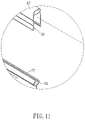
- FIG. 11 is an enlarged view of part F in FIG. 10 ;
- FIG. 12 is an enlarged view of part G in FIG. 10 ;
- FIG. 13 is a 3-dimensional unified view of the third embodiment of the present invention.
- the enclosed fence/railing set are shown in FIG. 1 , including a set of posts 11 and 12 , a set of beams 21 and 22 , a set of enclosed railing 3 , and a set of stakes 41 and 42 ; said posts 11 and 12 , said beams 21 and 22 , and said enclosed railing 3 are all aluminum extruded.
- One beam-fixing component 13 is fixed on top of posts 11 and 12 .
- Said beam-fixing component 13 is gate-shaped, with grooves 131 on its exterior wall and fixing hole 132 on its bottom. Fixing hole 132 allows the beams to fit in and then get fixed with screws.
- One beam-fixing component 133 is fixed on the bottom of posts 11 and 12 .
- Said beam-fixing component 133 is gate-shaped, with groove 134 and fixing hole 135 on its exterior for fixing beams.
- One cap 14 is set on top of posts 11 and 12 .
- Said cap 14 can be cone-shaped, round, or in other shapes.
- One long tenon 141 is set on the bottom of cap 14 , so that cap 14 can match itself with groove 121 while assembling.
- Said beams 21 and 22 are respectively the upper beam 21 and the lower beam 22 as shown in FIG. 3 .
- Said upper beam 21 is a square tube with grooves on its exterior.
- One plate 212 lies on the bottom of it, with tenon 213 and protruding tip 214 on its interior. Groove 215 and tilting brim 216 are on the exterior of plate 212 .
- said lower beam 22 has a plate 222 that matches the plate of the upper beam.
- said railing is set between upper beam 21 and lower beam 22 , including stick 31 and small plate 32 .
- a surrounding groove 311 lies on both tips of stick 31 , which allows it to match with long tenon 213 of the upper beam and the lower beam.
- Small plate 32 is linked with a connecting plate 321 .
- Said small plate 32 is connected to a connecting plate 321 with its upper part; there are folds 322 on two sides of connecting plate 321 , allowing plate 321 to be fixed to long tenon 213 of said upper beam and move along the inner side of said beam.
- One separating strip 323 is set below small plate 32 , and on both sides of said separating strip are arch-shaped post 324 .
- small plate 32 When small plate 32 is set between separating posts 31 , it can be fixed to arch-shaped groove with said matching post 324 .
- another separating plate 33 is set within lower beam 22 and between two separating posts.
- the above mentioned stakes 41 and 42 are as shown in FIG. 5 .
- Hole 45 are linked with inner tube 44 .
- multi-angular tubes 47 are set on top of stakes 41 and 42 , with a round plate 46 fixed between said tube 47 and stakes 41 and 42 .
- This enables the stakes to be tightly fixed to posts 11 and 23 .
- Holes 48 on plate 46 are for the convenience of placing nails in.
- a railing is set as shown in FIG. 6 .
- Said railing is not only equipped with stakes that hold the ground tightly, but it is very convenient to transport/assemble/dissemble because it is aluminum extruded.
- the soil hardening agent filler design moreover, allows the set to be fixed solidly to the ground and can be used depending on various types of ground.
- said enclosed fence/railing set can also do without stakes 41 and 42 .
- posts 11 and 12 can also be fixed to non-soil ground (for example, wooden floor).
- said enclosed fence/railing set can also be complemented with check plate 67 and covering plate 68 between the upper and lower beams to make compartment in households.
- caps 63 can be fixed on top of posts 61 and 62 , whereas stakes 64 can be fixed below.
- Upper beam 65 and lower beam 66 are placed between posts 61 and 62
- check plate 67 and covering plate 68 are placed between upper beam 65 and lower beam 66 .
- hook 71 and buckle plate 72 are fixed to posts 61 and 62 .
- One end of hook 71 is fixed to said posts and the other end is a gate-shaped tube 73 .
- One long tenon 74 is set within said tube.
- Said buckle plate 72 is vertical and is fixed to said posts 61 and 62 on one end. There is one crack 75 on other side of said buckle plate.
- the top of said check plate 67 is formed as a C-shaped tube 77 , wherein protruding trail 78 enables it to be fixed to upper beam 65 .
- the lower part of said check plate 67 is formed as a gate-shaped tube 79 , wherein intruding trail 80 and fixing line 81 enables it to be fixed to said beam.
- Said covering plate 68 comprise of smaller -shaped plates that are fixed to one another.
- the interior of said -shaped plate 82 is equipped with protruding line 83 that allows each plate to be tightly fixed to one another.
- protruding buckle 84 On the exterior of plate 82 is protruding buckle 84 , which is fixed with intruding trail 80 when said plate 82 and check plate 67 are to be fixed together.
Abstract
An enclosed fence railing set includes a set of posts with tips and fixing components for an upper beam and lower beam on both sides thereof. The fence railing set also includes a set of beams including an upper beam and a lower beam wherein the upper beam and lower beam match the fixing components and wherein there are railings between the sets of beams. A set of stakes are provided for fixing the posts. Each of the stakes includes a tube extending upwardly from the stake and a plate separating the stake and tube with a number of holes in the plate.
Description
1. Field of the Invention
The present invention relates to a set of enclosed fence/railing set, including a set of posts, a set of beams, a set of railings, and a set of stakes, especially a set of enclosed fence or railings which is aluminum extruded. Different parts of the enclosed railing are linked up with one another by tenons for users to easily assemble/dissemble it and put it away. It is light and convenient for transportation. The present invention is also equipped with stakes which enables it to steadily hold the ground. Therefore, when assembled and used on the ground, the present invention is capable of enduring much external stress.
2. Description of the Prior Art
Fences, or railings, became part of our daily lives a long time ago. Living rooms and dining rooms are divided when railings are set up in the house. Railings can also be helpful to the old or the sick, so that they are able to move around. They can also be used to protect babies or young children. Railings are mostly used outside of the house in hallways. As for fences, they are used to create borders. When fences are near to the house, they circle around a yard. When they are farther away from the house, they are used to show where the larger borders are. In addition, they can also prevent captured or domesticated animals from escape or avoid attacks/intrusions from strangers/wild animals.
Most of the existing fences or railings are made of wood. In order to strengthen them, some of them are made of iron or other heavy materials. Nevertheless, whether they are made of wood or iron, they are drilled and then screwed together, and they are heavier as a whole. They are not flexible and hard to transport.
Accordingly, the present invention has been invented to solve the above-mentioned problems occurred in the prior art.
The present invention provides an enclosed fence/railing set, including a set of posts, a set of beams, a set of railings, and a set of stakes. Said posts, beams, and railings are all aluminum extruded for the convenience of disassembling, assembling, and storage.
Accordingly, an object of the present invention is to provide a set of railing which is capable of enduring much external stress. The stakes of the present invention have spiral lines on the outside, which allows the present invention to drill deep. The stakes are equipped with tubes inside, whereas there are pores on the walls of the tubes. After having filling in soil hardening agent and water in the tubes, the agent spreads to the ground and forms solid materials between the stakes and the ground. Therefore, upon completion of the assembling and stake-setting, the present invention will be capable of enduring external physical impacts.
The above purposes and structure of the present invention will be more apparent from the following detailed description taken in conjunction with the accompanying drawings:
For fuller understanding of the nature and objects of the invention, reference should be made to the following detailed description taken in conjunction with the accompanying drawings in which:
The enclosed fence/railing set are shown in FIG. 1 , including a set of posts 11 and 12, a set of beams 21 and 22, a set of enclosed railing 3, and a set of stakes 41 and 42; said posts 11 and 12, said beams 21 and 22, and said enclosed railing 3 are all aluminum extruded.
One beam-fixing component 13 is fixed on top of posts 11 and 12. Said beam-fixing component 13 is gate-shaped, with grooves 131 on its exterior wall and fixing hole 132 on its bottom. Fixing hole 132 allows the beams to fit in and then get fixed with screws. One beam-fixing component 133 is fixed on the bottom of posts 11 and 12. Said beam-fixing component 133 is gate-shaped, with groove 134 and fixing hole 135 on its exterior for fixing beams.
One cap 14 is set on top of posts 11 and 12. Said cap 14 can be cone-shaped, round, or in other shapes. One long tenon 141 is set on the bottom of cap 14, so that cap 14 can match itself with groove 121 while assembling.
Said beams 21 and 22 are respectively the upper beam 21 and the lower beam 22 as shown in FIG. 3 . Said upper beam 21 is a square tube with grooves on its exterior. One plate 212 lies on the bottom of it, with tenon 213 and protruding tip 214 on its interior. Groove 215 and tilting brim 216 are on the exterior of plate 212.
As shown in FIG. 4 , said lower beam 22 has a plate 222 that matches the plate of the upper beam. There is one long tenon 223 and one protruding tip 224 on the interior of said lower beam and one groove 225 and tilting brim 226 on its exterior.
As shown in FIG. 3 , said railing is set between upper beam 21 and lower beam 22, including stick 31 and small plate 32. A surrounding groove 311 lies on both tips of stick 31, which allows it to match with long tenon 213 of the upper beam and the lower beam. Small plate 32 is linked with a connecting plate 321.
Said small plate 32 is connected to a connecting plate 321 with its upper part; there are folds 322 on two sides of connecting plate 321, allowing plate 321 to be fixed to long tenon 213 of said upper beam and move along the inner side of said beam.
One separating strip 323 is set below small plate 32, and on both sides of said separating strip are arch-shaped post 324. When small plate 32 is set between separating posts 31, it can be fixed to arch-shaped groove with said matching post 324. Within lower beam 22 and between two separating posts, another separating plate 33 is set.
The above mentioned stakes 41 and 42 are as shown in FIG. 5 . There are spirals 43 on the exterior of said stakes 41 and 42, an inner tube 44, and holes 45. Hole 45 are linked with inner tube 44. When fixed stakes 41 and 42 to the ground, soil hardening agent (which can be either powder or liquid) and water shall be filled following on. Said agent shall flow into the ground along with water through holes 45. Then, said stakes will be firmly fixed to the ground and form a solid foundation.
As shown in FIG. 1 , multi-angular tubes 47 are set on top of stakes 41 and 42, with a round plate 46 fixed between said tube 47 and stakes 41 and 42. This enables the stakes to be tightly fixed to posts 11 and 23. Holes 48 on plate 46 are for the convenience of placing nails in.
Upon complete assembling, a railing is set as shown in FIG. 6. Said railing is not only equipped with stakes that hold the ground tightly, but it is very convenient to transport/assemble/dissemble because it is aluminum extruded. The soil hardening agent filler design, moreover, allows the set to be fixed solidly to the ground and can be used depending on various types of ground.
As shown in FIGS. 7A and 7B , said enclosed fence/railing set can also do without stakes 41 and 42. With square bottom plates 51 and 51, posts 11 and 12 can also be fixed to non-soil ground (for example, wooden floor).
As shown in FIG. 8 , said enclosed fence/railing set can also be complemented with check plate 67 and covering plate 68 between the upper and lower beams to make compartment in households.
As shown in FIG. 8 , caps 63 can be fixed on top of posts 61 and 62, whereas stakes 64 can be fixed below. Upper beam 65 and lower beam 66 are placed between posts 61 and 62, whereas check plate 67 and covering plate 68 are placed between upper beam 65 and lower beam 66.
As shown in FIG. 9 , hook 71 and buckle plate 72 are fixed to posts 61 and 62. One end of hook 71 is fixed to said posts and the other end is a gate-shaped tube 73. One long tenon 74 is set within said tube.
Said buckle plate 72 is vertical and is fixed to said posts 61 and 62 on one end. There is one crack 75 on other side of said buckle plate.
As shown in FIGS. 10 , 11, and 12, the top of said check plate 67 is formed as a C-shaped tube 77, wherein protruding trail 78 enables it to be fixed to upper beam 65. The lower part of said check plate 67 is formed as a gate-shaped tube 79, wherein intruding trail 80 and fixing line 81 enables it to be fixed to said beam. Said covering plate 68 comprise of smaller  -shaped plates that are fixed to one another. The interior of said -shaped
 plate 82 is equipped with protruding line 83 that allows each plate to be tightly fixed to one another. On the exterior of plate 82 is protruding buckle 84, which is fixed with intruding trail 80 when said plate 82 and check plate 67 are to be fixed together.
In conclusion, from the above the components of enclosed fence/railing set of the present invention are aluminum alloy extruded, wherein they are hooked up with matching grooves and are not therefore seen in conventional enclosed fence/railing sets. Also, the present invention has not yet been made public, which is consistent with relevant Patent Law.
Although the above-mentioned embodiments of the present invention have been described for illustrative purposes, those skilled in the art will appreciate that various modifications, additions and substitutions are possible, without departing from the scope and spirit of the invention as disclosed in the accompanying claims.
Claims (6)
1. An enclosed fence railing set, comprising:
a set of two posts comprising fixing components on both posts for engaging an upper beam and a lower beam;
a set of beams including an upper beam and a lower beam, wherein the upper and lower beams engage said fixing components, and wherein there are railings extending between said set of beams and engaged within respective longitudinal channels in said upper and lower beams;
the railings comprising:
a covering plate comprising a plurality of parallel vertical elongated C-shaped plates that are fixed to one another, and
a check plate comprising a body having unitarily formed upper and lower parts,
wherein the upper part of said check plate is formed with a longitudinal channel defining a C-shaped tube, the exterior of the C-shaped tube comprising folds that allow said tube to be received within said longitudinal channel in said upper beam,
wherein the lower part of said check plate is formed with a longitudinal channel defining a gate-shaped tube, a lower part of said gate-shaped tube being folded inwardly to form opposed sides of the gate-shaped tube, each opposed side having an inwardly protruding trail and exterior grooves defining a protruding line that allow an upper end of each of said C-shaped plates of said covering plate to be tightly fixed to said check plate within said longitudinal channel of said gate-shaped tube, each of said C-shaped plates including a protruding buckle which is engaged with one of said protruding trails such that said C-shaped plates and said check plate are fixed together and lower ends of said C-shaped plates are received within said longitudinal channel in said lower beam; and
a set of stakes for fixing said posts in a location on the ground, wherein said stakes each include an upwardly extending hollow multi-angular tube extending upwardly from said stakes and an outwardly extending plate fixed between each of said stakes and the ground,
wherein each of said outwardly extending plates includes holes for the placing of nails into the ground, and wherein said hollow tubes are received within said posts to set up said posts on the ground.
2. An enclosed fence railing set as claimed in claim 1 , wherein there are caps on the top of said posts, wherein the caps are conical or round in shape.
3. The enclosed fence railing set as claimed in claim 1 , wherein said upper and lower beams, said check plate and said covering plate.
4. The enclosed fence railing set as claimed in claim 3 , wherein each said hook is connected to one of said posts at one end and comprise a gate-shaped tube at the other end, wherein a long tenon is disposed in said gate-shaped tube of said hook for engaging an end of said upper or lower beam.
5. The enclosed fence railing set as claimed in claim 3 , wherein each of said buckle plates is vertically set, with one end fixed to one of said posts and the other end comprising a crack for receiving an edge of said check plate.
6. The enclosed fence railing set as claimed in claim 1 , wherein the body of said check plate, said C-shaped tube, and said gate-shaped tube are fixed with one another seamlessly.
Priority Applications (1)
| Application Number | Priority Date | Filing Date | Title |
|---|---|---|---|
| US11/621,786 US7503550B2 (en) | 2007-01-10 | 2007-01-10 | Enclosed fence/railing set |
Applications Claiming Priority (1)
| Application Number | Priority Date | Filing Date | Title |
|---|---|---|---|
| US11/621,786 US7503550B2 (en) | 2007-01-10 | 2007-01-10 | Enclosed fence/railing set |
Publications (2)
| Publication Number | Publication Date |
|---|---|
| US20080164451A1 US20080164451A1 (en) | 2008-07-10 |
| US7503550B2 true US7503550B2 (en) | 2009-03-17 |
Family
ID=39593483
Family Applications (1)
| Application Number | Title | Priority Date | Filing Date |
|---|---|---|---|
| US11/621,786 Active 2027-03-29 US7503550B2 (en) | 2007-01-10 | 2007-01-10 | Enclosed fence/railing set |
Country Status (1)
| Country | Link |
|---|---|
| US (1) | US7503550B2 (en) |
Cited By (24)
| Publication number | Priority date | Publication date | Assignee | Title |
|---|---|---|---|---|
| US20080230756A1 (en) * | 2004-05-11 | 2008-09-25 | Neame Macdonald | Supporting Member |
| US20080230758A1 (en) * | 2007-03-23 | 2008-09-25 | Mfpf, Inc. | Barrier Fencing System |
| US20090114895A1 (en) * | 2007-09-28 | 2009-05-07 | Railing Dynamics Inc. | Post and railing assembly with support bracket covers |
| US20090146122A1 (en) * | 2007-12-05 | 2009-06-11 | Fortress Iron, Lp | Installable top accent panels for a barrier system |
| US20090152523A1 (en) * | 2007-12-18 | 2009-06-18 | Erwin Ronald D | Snap-together fencing components |
| US20090183354A1 (en) * | 2007-01-29 | 2009-07-23 | Mcginness William G | Compression Post Mount |
| US20090314220A1 (en) * | 2008-06-19 | 2009-12-24 | Groh William S | Modular Fence Panel and Connecting Member for Welded Wire Kennel |
| US20100038612A1 (en) * | 2008-08-13 | 2010-02-18 | Bob Hazlett | Fencing system for campfire |
| US20100044661A1 (en) * | 2007-11-19 | 2010-02-25 | Weiner Steven L | Portable barrier apparatus |
| US20110084577A1 (en) * | 2009-10-09 | 2011-04-14 | Leatherman Todd R | Modular integrated outdoor locker with enhanced cap, and system |
| US20110084576A1 (en) * | 2009-10-09 | 2011-04-14 | Leatherman Todd R | Modular integrated outdoor locker and system |
| US20110095254A1 (en) * | 2009-10-27 | 2011-04-28 | Min-Ju Chung | Modular Fence Device |
| US20120174484A1 (en) * | 2011-01-11 | 2012-07-12 | Azek Building Products, Inc. | Adjustable gate |
| US8286925B1 (en) * | 2008-07-31 | 2012-10-16 | White Jr William J | Universal post |
| US20130051910A1 (en) * | 2011-08-28 | 2013-02-28 | Shlomo HEN | Modular infant furniture and connectors therefor |
| US20130153843A1 (en) * | 2011-06-20 | 2013-06-20 | Eddie Leach | Do-it-yourself fence |
| US20140264218A1 (en) * | 2013-03-13 | 2014-09-18 | Guardian Pool Fence Systems, Inc. | Fence and method of assembling same |
| US20160305151A1 (en) * | 2015-04-15 | 2016-10-20 | Thomas Bodrogi | Fencing Assembly |
| US9784031B2 (en) | 2014-10-16 | 2017-10-10 | Dee Volin | Adjustable gate, having multiple guttering systems, multiple impact-absorbing systems, multiple anti-warping systems, multiple anti-sagging systems, multiple personal-injury-eliminating systems, and self-centering angle-locking safety truss |
| US10161161B2 (en) * | 2015-06-12 | 2018-12-25 | Jihong Yin | Enclosing wallboard firm-connection device |
| US10808419B2 (en) | 2012-08-10 | 2020-10-20 | Brett Jason Richison | Fence system |
| US11377871B2 (en) * | 2019-01-30 | 2022-07-05 | TransGard LLC | Anchoring system for a fence |
| USD1012637S1 (en) | 2020-11-20 | 2024-01-30 | Steve Bright | Yard stake |
| US11933099B1 (en) | 2020-05-18 | 2024-03-19 | Brett Jason Richison | Reinforced gate that facilitates field assembly in multiple configurations |
Families Citing this family (4)
| Publication number | Priority date | Publication date | Assignee | Title |
|---|---|---|---|---|
| CN103485580A (en) * | 2013-10-12 | 2014-01-01 | 江苏耀捷建设工程有限公司 | Novel safety fence |
| US11522488B2 (en) * | 2019-05-07 | 2022-12-06 | Solar Foundations Usa, Inc. | Vertical column |
| AT523350B1 (en) * | 2020-01-08 | 2023-01-15 | Bernhard Berghofer | Support element construction for a balcony railing and use of the same |
| CN111852180B (en) * | 2020-08-25 | 2021-10-08 | 台州云造智能科技有限公司 | Engineering protection device |
Citations (11)
| Publication number | Priority date | Publication date | Assignee | Title |
|---|---|---|---|---|
| US3037593A (en) * | 1959-06-25 | 1962-06-05 | Clifford L Webster | Partition construction |
| US3304683A (en) * | 1964-02-05 | 1967-02-21 | Texas Instruments Inc | Wall structure |
| US3776522A (en) * | 1972-05-15 | 1973-12-04 | W Bartlett | Fence post construction |
| FR2571771A1 (en) * | 1984-10-12 | 1986-04-18 | Rovera Resine Srl | Plastic moulding for fence posts |
| US5695174A (en) * | 1996-01-18 | 1997-12-09 | Tsai; Yang Wen | Fence |
| US5702090A (en) * | 1995-08-07 | 1997-12-30 | Vinylex Corporation | Snap together plastic fence |
| US5904343A (en) * | 1995-12-11 | 1999-05-18 | North American Pipe Corporation | Adjustable width panel assembly |
| US5988599A (en) * | 1997-02-19 | 1999-11-23 | Kroy Building Products, Inc. | Fence system |
| US6152428A (en) * | 1997-12-18 | 2000-11-28 | Simioni; Lino | Fence system |
| US6478287B2 (en) * | 2000-06-02 | 2002-11-12 | U.S. Fence, Llc | Plastic fence panel |
| US20060113517A1 (en) * | 2004-11-30 | 2006-06-01 | Royal Group Technologies Limited | Modular fencing system and method for constructing same |
-
2007
- 2007-01-10 US US11/621,786 patent/US7503550B2/en active Active
Patent Citations (11)
| Publication number | Priority date | Publication date | Assignee | Title |
|---|---|---|---|---|
| US3037593A (en) * | 1959-06-25 | 1962-06-05 | Clifford L Webster | Partition construction |
| US3304683A (en) * | 1964-02-05 | 1967-02-21 | Texas Instruments Inc | Wall structure |
| US3776522A (en) * | 1972-05-15 | 1973-12-04 | W Bartlett | Fence post construction |
| FR2571771A1 (en) * | 1984-10-12 | 1986-04-18 | Rovera Resine Srl | Plastic moulding for fence posts |
| US5702090A (en) * | 1995-08-07 | 1997-12-30 | Vinylex Corporation | Snap together plastic fence |
| US5904343A (en) * | 1995-12-11 | 1999-05-18 | North American Pipe Corporation | Adjustable width panel assembly |
| US5695174A (en) * | 1996-01-18 | 1997-12-09 | Tsai; Yang Wen | Fence |
| US5988599A (en) * | 1997-02-19 | 1999-11-23 | Kroy Building Products, Inc. | Fence system |
| US6152428A (en) * | 1997-12-18 | 2000-11-28 | Simioni; Lino | Fence system |
| US6478287B2 (en) * | 2000-06-02 | 2002-11-12 | U.S. Fence, Llc | Plastic fence panel |
| US20060113517A1 (en) * | 2004-11-30 | 2006-06-01 | Royal Group Technologies Limited | Modular fencing system and method for constructing same |
Cited By (33)
| Publication number | Priority date | Publication date | Assignee | Title |
|---|---|---|---|---|
| US20080230756A1 (en) * | 2004-05-11 | 2008-09-25 | Neame Macdonald | Supporting Member |
| US20090183354A1 (en) * | 2007-01-29 | 2009-07-23 | Mcginness William G | Compression Post Mount |
| US7802351B2 (en) * | 2007-01-29 | 2010-09-28 | Homeland Vinyl Products, Inc. | Compression post mount |
| US20080230758A1 (en) * | 2007-03-23 | 2008-09-25 | Mfpf, Inc. | Barrier Fencing System |
| US8820722B2 (en) * | 2007-03-23 | 2014-09-02 | Gary L. Reinert, Sr. | Barrier fencing system |
| US20120049143A1 (en) * | 2007-03-23 | 2012-03-01 | Mfpf, Inc. | Barrier Fencing System |
| US20090114895A1 (en) * | 2007-09-28 | 2009-05-07 | Railing Dynamics Inc. | Post and railing assembly with support bracket covers |
| US7731160B2 (en) * | 2007-09-28 | 2010-06-08 | Railing Dynamics, Inc. | Post and railing assembly with support bracket covers |
| US7909310B2 (en) * | 2007-11-19 | 2011-03-22 | Weiner Steven L | Portable barrier apparatus |
| US20100044661A1 (en) * | 2007-11-19 | 2010-02-25 | Weiner Steven L | Portable barrier apparatus |
| US20090146122A1 (en) * | 2007-12-05 | 2009-06-11 | Fortress Iron, Lp | Installable top accent panels for a barrier system |
| US20090152523A1 (en) * | 2007-12-18 | 2009-06-18 | Erwin Ronald D | Snap-together fencing components |
| US20090314220A1 (en) * | 2008-06-19 | 2009-12-24 | Groh William S | Modular Fence Panel and Connecting Member for Welded Wire Kennel |
| US8286925B1 (en) * | 2008-07-31 | 2012-10-16 | White Jr William J | Universal post |
| US20100038612A1 (en) * | 2008-08-13 | 2010-02-18 | Bob Hazlett | Fencing system for campfire |
| US20110084577A1 (en) * | 2009-10-09 | 2011-04-14 | Leatherman Todd R | Modular integrated outdoor locker with enhanced cap, and system |
| US20110084576A1 (en) * | 2009-10-09 | 2011-04-14 | Leatherman Todd R | Modular integrated outdoor locker and system |
| US20110095254A1 (en) * | 2009-10-27 | 2011-04-28 | Min-Ju Chung | Modular Fence Device |
| US20120174484A1 (en) * | 2011-01-11 | 2012-07-12 | Azek Building Products, Inc. | Adjustable gate |
| US8713853B2 (en) * | 2011-01-11 | 2014-05-06 | Azek Building Products, Inc. | Adjustable gate |
| US20130153843A1 (en) * | 2011-06-20 | 2013-06-20 | Eddie Leach | Do-it-yourself fence |
| US9631396B2 (en) * | 2011-06-20 | 2017-04-25 | Eddie Leach | Do-it-yourself fence |
| US20130051910A1 (en) * | 2011-08-28 | 2013-02-28 | Shlomo HEN | Modular infant furniture and connectors therefor |
| US8881326B2 (en) * | 2011-08-28 | 2014-11-11 | Shlomo HEN | Modular infant furniture and connectors therefor |
| US10808419B2 (en) | 2012-08-10 | 2020-10-20 | Brett Jason Richison | Fence system |
| US9580930B2 (en) * | 2013-03-13 | 2017-02-28 | Guardian Pool Fence Systems, Inc. | Fence and method of assembling same |
| US20140264218A1 (en) * | 2013-03-13 | 2014-09-18 | Guardian Pool Fence Systems, Inc. | Fence and method of assembling same |
| US9784031B2 (en) | 2014-10-16 | 2017-10-10 | Dee Volin | Adjustable gate, having multiple guttering systems, multiple impact-absorbing systems, multiple anti-warping systems, multiple anti-sagging systems, multiple personal-injury-eliminating systems, and self-centering angle-locking safety truss |
| US20160305151A1 (en) * | 2015-04-15 | 2016-10-20 | Thomas Bodrogi | Fencing Assembly |
| US10161161B2 (en) * | 2015-06-12 | 2018-12-25 | Jihong Yin | Enclosing wallboard firm-connection device |
| US11377871B2 (en) * | 2019-01-30 | 2022-07-05 | TransGard LLC | Anchoring system for a fence |
| US11933099B1 (en) | 2020-05-18 | 2024-03-19 | Brett Jason Richison | Reinforced gate that facilitates field assembly in multiple configurations |
| USD1012637S1 (en) | 2020-11-20 | 2024-01-30 | Steve Bright | Yard stake |
Also Published As
| Publication number | Publication date |
|---|---|
| US20080164451A1 (en) | 2008-07-10 |
Similar Documents
| Publication | Publication Date | Title |
|---|---|---|
| US7503550B2 (en) | Enclosed fence/railing set | |
| US6923195B2 (en) | Skeleton frame assembly for a tent | |
| US9422711B1 (en) | Screen support assembly with wide lateral support efficiency | |
| US9605425B1 (en) | Screen support assembly with wide lateral support efficiency | |
| US8864096B1 (en) | Anchor device for a wooden post | |
| US6499435B2 (en) | Portable corral | |
| US9458645B1 (en) | Modular fence kit | |
| EP2196112A1 (en) | Removable guardrail framework | |
| US9279271B2 (en) | Connected fence for collecting rain water | |
| US9995034B2 (en) | Portable temporary structure | |
| US20160339314A1 (en) | A Goal and Shelter Device | |
| US20080277639A1 (en) | Fence structure | |
| EP2677097A2 (en) | Do-it-yourself fence | |
| US20190203484A1 (en) | Hand Railing System | |
| KR102181409B1 (en) | Prefabricated cat tower | |
| CA2573569C (en) | Enclosed fence/railing set | |
| DE102007023501B4 (en) | Railing system with enclosed fence | |
| US20160067624A1 (en) | Playhouse Assembly | |
| US20180119445A1 (en) | Fence Safety and Anti-Theft System | |
| NZ555157A (en) | Enclosed fence/railing set | |
| US163559A (en) | Improvement in portable sheds | |
| KR200474034Y1 (en) | A self-assemble house for pet | |
| KR102301811B1 (en) | Prefabricated Pergola | |
| KR101147454B1 (en) | Bungalow of sixteen angles | |
| CN213231227U (en) | Portal frame |
Legal Events
| Date | Code | Title | Description |
|---|---|---|---|
| STCF | Information on status: patent grant |
Free format text: PATENTED CASE |
|
| FPAY | Fee payment |
Year of fee payment: 4 |
|
| FPAY | Fee payment |
Year of fee payment: 8 |
|
| MAFP | Maintenance fee payment |
Free format text: PAYMENT OF MAINTENANCE FEE, 12TH YR, SMALL ENTITY (ORIGINAL EVENT CODE: M2553); ENTITY STATUS OF PATENT OWNER: SMALL ENTITY Year of fee payment: 12 |