US7506516B2 - Concentric catalytic combustor - Google Patents
Concentric catalytic combustor Download PDFInfo
- Publication number
- US7506516B2 US7506516B2 US11/156,338 US15633805A US7506516B2 US 7506516 B2 US7506516 B2 US 7506516B2 US 15633805 A US15633805 A US 15633805A US 7506516 B2 US7506516 B2 US 7506516B2
- Authority
- US
- United States
- Prior art keywords
- fluid flow
- pressure boundary
- catalytic
- combustor
- flow
- Prior art date
- Legal status (The legal status is an assumption and is not a legal conclusion. Google has not performed a legal analysis and makes no representation as to the accuracy of the status listed.)
- Expired - Fee Related, expires
Links
- 230000003197 catalytic effect Effects 0.000 title claims abstract description 87
- 239000012530 fluid Substances 0.000 claims abstract description 72
- 239000000463 material Substances 0.000 claims abstract description 25
- 239000012809 cooling fluid Substances 0.000 claims description 26
- 238000001816 cooling Methods 0.000 claims description 17
- 239000000446 fuel Substances 0.000 claims description 14
- 238000007084 catalytic combustion reaction Methods 0.000 claims description 12
- 238000000034 method Methods 0.000 claims description 7
- 238000004891 communication Methods 0.000 claims description 6
- 238000011144 upstream manufacturing Methods 0.000 claims description 6
- 239000000203 mixture Substances 0.000 description 37
- 238000002485 combustion reaction Methods 0.000 description 32
- 239000003570 air Substances 0.000 description 7
- 239000007789 gas Substances 0.000 description 7
- 230000002093 peripheral effect Effects 0.000 description 4
- 238000005219 brazing Methods 0.000 description 3
- 239000003054 catalyst Substances 0.000 description 3
- 238000006243 chemical reaction Methods 0.000 description 3
- 239000000567 combustion gas Substances 0.000 description 3
- 238000002156 mixing Methods 0.000 description 3
- 238000003466 welding Methods 0.000 description 3
- XEEYBQQBJWHFJM-UHFFFAOYSA-N Iron Chemical compound [Fe] XEEYBQQBJWHFJM-UHFFFAOYSA-N 0.000 description 2
- PXHVJJICTQNCMI-UHFFFAOYSA-N Nickel Chemical compound [Ni] PXHVJJICTQNCMI-UHFFFAOYSA-N 0.000 description 2
- KDLHZDBZIXYQEI-UHFFFAOYSA-N Palladium Chemical compound [Pd] KDLHZDBZIXYQEI-UHFFFAOYSA-N 0.000 description 2
- 239000000956 alloy Substances 0.000 description 2
- 229910045601 alloy Inorganic materials 0.000 description 2
- 239000012080 ambient air Substances 0.000 description 2
- 230000008901 benefit Effects 0.000 description 2
- VNWKTOKETHGBQD-UHFFFAOYSA-N methane Chemical compound C VNWKTOKETHGBQD-UHFFFAOYSA-N 0.000 description 2
- 239000007800 oxidant agent Substances 0.000 description 2
- 230000001590 oxidative effect Effects 0.000 description 2
- BASFCYQUMIYNBI-UHFFFAOYSA-N platinum Chemical compound [Pt] BASFCYQUMIYNBI-UHFFFAOYSA-N 0.000 description 2
- 229910052684 Cerium Inorganic materials 0.000 description 1
- VYZAMTAEIAYCRO-UHFFFAOYSA-N Chromium Chemical compound [Cr] VYZAMTAEIAYCRO-UHFFFAOYSA-N 0.000 description 1
- RYGMFSIKBFXOCR-UHFFFAOYSA-N Copper Chemical compound [Cu] RYGMFSIKBFXOCR-UHFFFAOYSA-N 0.000 description 1
- QCWXUUIWCKQGHC-UHFFFAOYSA-N Zirconium Chemical compound [Zr] QCWXUUIWCKQGHC-UHFFFAOYSA-N 0.000 description 1
- 239000004480 active ingredient Substances 0.000 description 1
- 230000004323 axial length Effects 0.000 description 1
- 239000010953 base metal Substances 0.000 description 1
- GWXLDORMOJMVQZ-UHFFFAOYSA-N cerium Chemical compound [Ce] GWXLDORMOJMVQZ-UHFFFAOYSA-N 0.000 description 1
- 229910052804 chromium Inorganic materials 0.000 description 1
- 239000011651 chromium Substances 0.000 description 1
- 229910017052 cobalt Inorganic materials 0.000 description 1
- 239000010941 cobalt Substances 0.000 description 1
- GUTLYIVDDKVIGB-UHFFFAOYSA-N cobalt atom Chemical compound [Co] GUTLYIVDDKVIGB-UHFFFAOYSA-N 0.000 description 1
- 229910052802 copper Inorganic materials 0.000 description 1
- 239000010949 copper Substances 0.000 description 1
- 238000010586 diagram Methods 0.000 description 1
- 239000000295 fuel oil Substances 0.000 description 1
- 229910052741 iridium Inorganic materials 0.000 description 1
- GKOZUEZYRPOHIO-UHFFFAOYSA-N iridium atom Chemical compound [Ir] GKOZUEZYRPOHIO-UHFFFAOYSA-N 0.000 description 1
- 229910052742 iron Inorganic materials 0.000 description 1
- 229910052747 lanthanoid Inorganic materials 0.000 description 1
- 150000002602 lanthanoids Chemical class 0.000 description 1
- 229910052746 lanthanum Inorganic materials 0.000 description 1
- FZLIPJUXYLNCLC-UHFFFAOYSA-N lanthanum atom Chemical compound [La] FZLIPJUXYLNCLC-UHFFFAOYSA-N 0.000 description 1
- 238000003754 machining Methods 0.000 description 1
- 238000012423 maintenance Methods 0.000 description 1
- WPBNNNQJVZRUHP-UHFFFAOYSA-L manganese(2+);methyl n-[[2-(methoxycarbonylcarbamothioylamino)phenyl]carbamothioyl]carbamate;n-[2-(sulfidocarbothioylamino)ethyl]carbamodithioate Chemical compound [Mn+2].[S-]C(=S)NCCNC([S-])=S.COC(=O)NC(=S)NC1=CC=CC=C1NC(=S)NC(=O)OC WPBNNNQJVZRUHP-UHFFFAOYSA-L 0.000 description 1
- 238000004519 manufacturing process Methods 0.000 description 1
- 229910044991 metal oxide Inorganic materials 0.000 description 1
- 150000004706 metal oxides Chemical class 0.000 description 1
- 239000003345 natural gas Substances 0.000 description 1
- 229910052759 nickel Inorganic materials 0.000 description 1
- 229910000510 noble metal Inorganic materials 0.000 description 1
- 229910052762 osmium Inorganic materials 0.000 description 1
- SYQBFIAQOQZEGI-UHFFFAOYSA-N osmium atom Chemical compound [Os] SYQBFIAQOQZEGI-UHFFFAOYSA-N 0.000 description 1
- 229910052763 palladium Inorganic materials 0.000 description 1
- 229910052697 platinum Inorganic materials 0.000 description 1
- 239000010970 precious metal Substances 0.000 description 1
- 238000011084 recovery Methods 0.000 description 1
- 229910052703 rhodium Inorganic materials 0.000 description 1
- 239000010948 rhodium Substances 0.000 description 1
- MHOVAHRLVXNVSD-UHFFFAOYSA-N rhodium atom Chemical compound [Rh] MHOVAHRLVXNVSD-UHFFFAOYSA-N 0.000 description 1
- 230000000087 stabilizing effect Effects 0.000 description 1
- 238000006467 substitution reaction Methods 0.000 description 1
- 229910052720 vanadium Inorganic materials 0.000 description 1
- LEONUFNNVUYDNQ-UHFFFAOYSA-N vanadium atom Chemical compound [V] LEONUFNNVUYDNQ-UHFFFAOYSA-N 0.000 description 1
- 229910052726 zirconium Inorganic materials 0.000 description 1
Images


Classifications
-
- F—MECHANICAL ENGINEERING; LIGHTING; HEATING; WEAPONS; BLASTING
- F23—COMBUSTION APPARATUS; COMBUSTION PROCESSES
- F23R—GENERATING COMBUSTION PRODUCTS OF HIGH PRESSURE OR HIGH VELOCITY, e.g. GAS-TURBINE COMBUSTION CHAMBERS
- F23R3/00—Continuous combustion chambers using liquid or gaseous fuel
- F23R3/40—Continuous combustion chambers using liquid or gaseous fuel characterised by the use of catalytic means
-
- F—MECHANICAL ENGINEERING; LIGHTING; HEATING; WEAPONS; BLASTING
- F23—COMBUSTION APPARATUS; COMBUSTION PROCESSES
- F23C—METHODS OR APPARATUS FOR COMBUSTION USING FLUID FUEL OR SOLID FUEL SUSPENDED IN A CARRIER GAS OR AIR
- F23C2900/00—Special features of, or arrangements for combustion apparatus using fluid fuels or solid fuels suspended in air; Combustion processes therefor
- F23C2900/13002—Catalytic combustion followed by a homogeneous combustion phase or stabilizing a homogeneous combustion phase
Definitions
- This invention relates generally to gas turbine engines, and, in particular, to a catalytic combustor comprising concentric tubular pressure boundary elements.
- LCL lean catalytic, lean burn
- RCL rich catalytic, lean burn
- U.S. Pat. No. 6,174,159 describes an RCL method and apparatus for a gas turbine engine having a catalytic combustor using a backside cooled design.
- the catalytic combustor includes a plurality of catalytic modules comprising multiple cooling conduits, such as tubes, coated on an outside diameter with a catalytic material and supported in the catalytic combustor.
- a portion of a fuel/oxidant mixture is passed over the catalyst coated cooling conduits and is oxidized, while simultaneously, a portion of the fuel/oxidant enters the multiple cooling conduits and cools the catalyst.
- the exothermally catalyzed fluid then exits the catalytic combustion system and is mixed with the cooling fluid outside the system, creating a heated, combustible mixture.
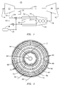
- FIG. 1 is a functional diagram of a gas turbine engine including a catalytic combustor.
- FIG. 2 illustrates an axial cross section of a concentric catalytic combustor taken along a direction of flow though the combustor.
- FIG. 3 is a cross sectional view of the concentric catalytic combustor of FIG. 2 as seen along plane 3 - 3 of FIG. 2 .
- FIG. 4 is a perspective view of a manifold assembly of the concentric catalytic combustor of FIG. 2 as seen along plane 4 - 4 of FIG. 2 .
- FIG. 5 is an end view of a manifold assembly of the concentric catalytic combustor of FIG. 2 as seen along plane 5 - 5 of FIG. 2 .
- FIG. 6 is a cross sectional view of a catalytic combustor comprising a plurality of concentric catalytic combustor modules arranged around a central region.
- FIG. 7 is a cross sectional view of another embodiment of the concentric catalytic combustor 28 of FIG. 2 as seen along plane 3 - 3 of FIG. 2 .
- FIG. 8 is partial cross sectional view, taken perpendicular to a direction of fluid flow, of an exemplary embodiment of a pressure boundary element.
- FIG. 9 is partial cross sectional view, taken perpendicular to a direction of fluid flow, of an exemplary embodiment of a pressure boundary element.
- FIG. 10 is partial cross sectional view, taken perpendicular to a direction of fluid flow, of an exemplary embodiment of a pressure boundary element.
- FIG. 11 is partial cross sectional view, taken perpendicular to a direction of fluid flow, of an exemplary embodiment of a pressure boundary element.
- FIG. 1 illustrates a gas turbine engine 10 having a compressor 12 for receiving a flow of filtered ambient air 14 and for producing a flow of compressed air 16 .
- the compressed air 16 is separated into a combustion mixture fluid flow 24 and a cooling fluid flow 26 , respectively, for introduction into a catalytic combustor 28 .
- the combustion mixture fluid flow 24 is mixed with a flow of a combustible fuel 20 , such as natural gas or fuel oil for example, provided by a fuel source 18 , prior to introduction into the catalytic combustor 28 .
- the cooling fluid flow 26 may be introduced directly into the catalytic combustor 28 without mixing with a combustible fuel.
- cooling fluid flow 26 may be mixed with a flow of combustible fuel 20 before being directed into the catalytic combustor 28 .
- a combustion mixture flow controller 22 may be used to control the amount of the combustion mixture fluid flow provided to the catalytic combustor 28 responsive to a gas turbine load condition.
- the combustion mixture fluid flow 24 and the cooling fluid flow 26 are separated by a pressure boundary element 30 .
- the pressure boundary element 30 is coated with a catalytic material 32 on the side exposed to the combustion mixture fluid flow 24 .
- the catalytic material 32 may have as an active ingredient of precious metals, Group VIII noble metals, base metals, metal oxides, or any combination thereof. Elements such as zirconium, vanadium, chromium, manganese, copper, platinum, palladium, osmium, iridium, rhodium, cerium, lanthanum, other elements of the lanthanide series, cobalt, nickel, iron, and the like may be used.
- the opposite side of the pressure boundary element 30 confines the cooling fluid flow 26 . While exposed to the catalytic material 32 , the combustion mixture fluid flow 24 is oxidized in an exothermic reaction, and the catalytic material 32 and the pressure boundary element 30 are cooled by the unreacted cooling fluid flow 26 , thereby absorbing a portion of the heat produced by the exothermic reaction.
- the flows 24 , 26 are mixed and combusted in a plenum, or combustion completion stage 34 , to produce a hot combustion gas 36 .
- the hot combustion gas 36 is received by a turbine 38 , where it is expanded to extract mechanical shaft power.
- a common shaft 40 interconnects the turbine 38 with the compressor 12 as well as an electrical generator (not shown) to provide mechanical power for compressing the ambient air 14 and for producing electrical power, respectively.
- the expanded combustion gas 42 may be exhausted directly to the atmosphere or it may be routed through additional heat recovery systems (not shown).
- FIG. 2 illustrates a cross section of an improved catalytic combustor 28 including a plurality of concentric tubular pressure boundary elements 46 arranged around a central core region 48 .
- FIG. 3 is a cross sectional view of the catalytic combustor 28 of FIG. 2 as seen along plane 3 - 3 of FIG. 2 , and shows the concentric arrangement of the tubular pressure boundary elements 46 around the central region 48 to form annular spaces, such as spaces 47 , 49 , 50 , for conducting respective fluid flows therethrough.
- the improved catalytic combustor 28 includes at least one annular space for conducting a first fluid flow therethrough and a second annular space, separate from the first annular space, for conducting a second fluid flow therethrough.
- a catalytic material is disposed in at least one of the spaces and is exposed to the fluid flowing therethrough.
- the term “concentric” includes pressure boundary elements centered around the central region 48 , not just about a central axis 56 . Accordingly, the elements 46 may be offset from one another so that the annular region formed there between may not be a symmetrical annular region.
- the term “tubular” is meant to include an element defining a flow channel having a circular, rectangular, hexagonal or other geometric cross section.
- Annular space is meant to refer to a peripheral space defined between a first tubular element and a second tubular element disposed around and spaced away from the first tubular element, such as a tubular element having a circular cross section (e.g., a cylindrical element), concentrically disposed around another cylindrical element to form a peripheral space there between.
- the combustor 28 may include a manifold assembly 45 attached to an upstream end 54 of the combustor 28 for retaining the pressure boundary elements 46 and receiving and directing fluid flows into the annular spaces 49 , 50 between the elements 46 .
- the annular spaces 49 , 50 may extend from the manifold assembly 45 to a combustor exit 62 .
- the manifold assembly 45 may include a one-piece assembly, or, in an embodiment, may include a two-piece assembly comprising a manifold 52 and an adapter 51 .
- a pilot burner 44 may be disposed in the central region 48 to provide a pilot flame for stabilizing flames in the combustion completion stage 34 under various engine loading conditions.
- a first set of spaces 49 may be configured to conduct respective portions 58 of the cooling fluid flow 26
- a second set of spaces 50 may be configured to conduct respective portions 60 of the combustion mixture fluid flow 24
- the spaces 50 conducting respective portions 60 of the combustion mixture fluid flow 24 may include a catalytic material 32 disposed on a surface of at least one of the pressure boundary elements 46 defining the space 50 and exposed to the portion 60 of the combustion mixture fluid flow 24 flowing in the space 50 , thereby forming a catalytically active space.
- an inner diameter surface 64 of one of the pressure boundary elements 46 forming an annular space 50 may include a catalytic material 32 .
- an outer diameter surface 66 of one of the pressure boundary elements 46 forming an annular space 50 may include a catalytic material 32 .
- an outer diameter surface 66 of a first boundary element and an inner diameter surface 64 of another pressure boundary element concentrically disposed around the first pressure boundary element may include a catalytic material 32 exposed to a portion 60 of the combustion mixture flow flowing in the space 50 defined by the first and second pressure boundary elements.
- the pressure boundary elements 46 may be configured to form a first set of annular spaces 49 comprising no catalytic material and conducting respective portions 58 of the cooling fluid flow 26 concentrically alternating with a second set of annular spaces 50 including a catalytic material 32 and conducting respective portions 60 of the combustion mixture fluid flow 24 .
- a space 49 having no catalytic material disposed on surfaces defining the space 49 remains catalytically inactive and may conduct a portion of the cooling fluid flow 26 to define a cooling space used to backside cool adjacent catalytically active spaces.
- the catalytic combustor 28 may comprise a series of concentric tubular pressure boundary elements 46 defining an alternating arrangement of catalytically active annular spaces interspersed by annular cooling spaces.
- a pressure boundary element 68 surrounding the central region 48 may include a catalytic material 32 on its inner diameter surface 70 to form a catalytically active channel, or may not include a catalytic material to allow the region to be used as a cooling space.
- a support structure 72 may be radially disposed between concentrically adjacent pressure boundary elements 46 within an annular space, such as space 47 , defined between elements 46 .
- the support structure 72 radially retains the adjacent pressure boundary elements 46 in a spaced configuration.
- the support structure 72 may include a corrugated element brazed or welded to one or both of the pressure boundary elements 46 and may extend along an axial length of the combustor 28 .
- the support structure may include fins or tubular elements disposed in a space 47 between two adjacent elements 46 .
- the support structure may be disposed in cooling spaces and/or catalytically active spaces.
- the support structure 72 itself may include a catalytic surface.
- FIG. 4 is a perspective view of the manifold assembly 45 of the concentric catalytic combustor 28 as seen along plane 4 - 4 of FIG. 2 .
- the manifold assembly 45 is configured to receive the combustion mixture fluid flow 24 and the cooling fluid flow 26 on an inlet side 74 and to distribute the flows 24 , 26 to the appropriate spaces between the pressure boundary elements 46 attached, such as by brazing, to an outlet side 76 of the manifold assembly 45 .
- respective portions 60 of the combustion mixture fluid flow 24 are delivered to catalytically active spaces and respective portions 58 of the cooling fluid flow 26 are delivered to cooling spaces.
- the manifold assembly 45 includes a plurality of angularly spaced apart radial passageways 78 for receiving the combustion mixture fluid flow 24 and conducting portions 60 of the combustion mixture fluid flow 24 into annular spaces 80 formed in the manifold assembly 45 in fluid communication with catalytically active spaces of the concentric catalytic combustor 28 .
- the combustion mixture fluid flow 24 may be introduced at a central opening 82 of the manifold assembly 52 and/or at an inlet (not shown) in fluid communication with a peripheral annular passageway 84 .
- the manifold assembly 52 may also include axial passageways 86 interspersed among and isolated from the radial passageways 78 and the annular spaces 80 .
- the axial passageways 86 receive the respective portions 58 of the cooling fluid flow 26 and conduct the portions 58 into cooling spaces of the concentric catalytic combustor 28 .
- the radial passageways 78 and the annular spaces 80 may be configured to receive and distribute the cooling fluid flow 26
- the axial passageways 86 may be configured to receive and distribute the combustion mixture fluid flow 24 .
- the manifold assembly 52 may include a manifold 52 and an adapter 51 attached to a downstream side 76 of the manifold 52 to connect the pressure boundary elements 46 to the manifold 52 and conduct the portions 58 , 60 of the fluid flows 24 , 26 from the manifold 52 into the appropriate spaces 49 , 50 .
- the adapter 51 may include annular recesses 53 adapted for receiving the upstream ends 55 of the respective pressure boundary elements 46 .
- the upstream ends 55 of the pressure boundary elements 46 may be mechanically attached to the adapter 51 , for example, by press fitting, brazing, or welding.
- the adapter 51 includes passageways 57 extending upstream from the recesses 53 through the adapter 51 to allow fluid communication between the axial passageways 86 and the spaces 49 , 50 between the pressure boundary elements 46 installed into the recesses 53 .
- the adapter 51 may be welded or brazed to the downstream side 76 of the manifold 52 so that the manifold assembly 45 may be formed in two pieces to reduce a machining complexity required to manufacture the assembly 45 .
- staging of the combustible mixture fluid flow 24 to the catalytic combustor 28 may be accomplished by configuring the combustion mixture flow controller 22 to control the combustible mixture fluid flow 24 to a plurality of catalytically active spaces independently of other catalytically active spaces.
- the combustion mixture flow controller 22 may be configured to control the combustion mixture flow responsive to a turbine load condition so that under partial loading, only a portion of the catalytically active spaces are fueled, and under full loading of the gas turbine, all of the catalytically active spaces are fueled.
- a plurality of concentric catalytic combustion modules 88 may be disposed around a central region 90 to form a catalytic combustor 86 .
- Each module 88 may include a plurality of concentric tubular pressure boundary elements 46 forming annular spaces 50 therebetween.
- a first set of spaces 49 of each module 88 may conduct a cooling fluid flow and a second set of spaces 50 may conduct a combustible mixture fluid flow.
- a catalytic surface disposed in the annular spaces 50 conducting a combustible mixture flow (such as on an inner diameter and/or outer diameter surface of the pressure boundary elements defining the spaces 50 , as described previously) is exposed to the combustible mixture fluid flow, thereby forming a catalytically active space.
- Spaces 49 conducting the cooling fluid define cooling spaces providing backside cooling for the catalytically active spaces.
- catalytically active spaces may be alternated with cooling spaces in each of the catalytic combustion modules to provide a backside cooled, concentric catalytic combustion module 88 .
- Each catalytic module 88 may include a manifold (not shown) attached to an upstream end of the module 88 for directing the combustion mixture flow into catalytically active spaces and the cooling flow into the cooling spaces.
- a pilot burner (not shown) may be disposed in the central region 90 .
- a catalytic combustion module 88 may be disposed in the central region 90 .
- a pilot burner 44 may be disposed in a central region 48 of one or more of the catalytic combustion modules 88 forming the catalytic combustor 86 .
- FIG. 7 is a cross sectional view of another embodiment of the concentric catalytic combustor 28 of FIG. 2 as seen along plane 3 - 3 of FIG. 2 .
- Each tubular pressure boundary element 90 separates a first portion of a fluid flow from a second portion of the fluid flow and includes a wall 96 having separate flow paths 98 for conducting another fluid flow within the wall 96 .
- the catalytic combustor 28 includes a plurality of concentric tubular pressure boundary elements 90 having respective longitudinal flow axes (for example, central axis 56 as shown in FIG. 2 ) forming a plurality of concentric annular spaces 92 conducting respective portions 94 , 94 of a combustible mixture fluid flow 24 .
- Each of the tubular pressure boundary elements 90 includes a wall 96 having a plurality of separate, longitudinally oriented flow paths 98 annularly disposed within the wall 96 .
- the longitudinally oriented flow paths 98 may be oriented parallel with the central axis 56 , or may be configured to spiral about the central axis 56 .
- the flow paths 98 within the wall 96 conduct respective portions 100 , 101 of a cooling fluid flow 26 therethrough.
- a catalytic material 32 may be disposed on respective surfaces 102 , 103 of the pressure boundary elements and exposed to one or more respective portions 94 , 95 of combustible fluid flow 24 .
- the catalytic material 32 may be disposed on one of the surfaces, or a portion thereof (such as inner diameter surface 103 or an outer diameter surface 102 ) of adjacent elements 90 having opposed surfaces 102 , 103 forming an annular space 92 therebetween.
- the catalytic material 32 may be disposed on both surfaces 102 , 103 , or portions thereof, forming the annular space 92 .
- each of the plurality of separate flow paths 98 formed in the wall 96 of the pressure boundary element 90 includes a hexagonal cross section, so that the plurality of the flow paths 98 form an annular honeycomb configuration with in the wall 96 .
- FIG. 8 depicts the wall 96 as including two annular rings 105 , 106 of spaced apart flow paths 98
- the wall 96 may include any number of rings to achieve, for example, a desired rigidity.
- the flow paths 98 may be sized and shaped to achieve a desired structural and/or cooling characteristic.
- FIGS. 9-11 Other exemplary geometric configurations of flow path cross sections are shown in FIGS. 9-11 .
- FIG. 9 shows a partial honeycomb cross section configuration including rounded portions 108 on the surfaces 102 , 103 of the boundary element 90 .
- FIG. 10 shows a corrugated cross section configuration
- FIG. 11 shows a rectangular cross section configuration.
- Such pressure boundary elements 90 may be formed from two or more corrugated sheets, having corrugations corresponding to desired flow path cross sections, of a high temperature resistant alloy, such as Haynes® 214TM or 230®, laid on top of one another. The sheets may be aligned to form the desired flow paths and attached at points of contact 110 as shown in FIG.
- the points of contact 110 may be welded, such as by resistance seam welding, but preferably by being brazed together using, for example, brazing alloys such as AWS A5.8 BNi-5 (AMS 4782), so that thermal conduction may be optimize compared to other welding techniques.
- the resulting attached sheets may then be cut to a desired length to and then rolled for example, into a cylinder, and connected where the edges of the rolled sheet meet to form a tubular pressure boundary element.
- the diameters of the cylinder may be varied so that a set of pressure boundary elements used to form a catalytic combustor may be nested to provide a concentric arrangement.
- corrugated surfaces such as surfaces 102 , 103
- Advantages of providing corrugated surfaces include providing an increased surface area compared to a flat surface, thereby allowing an overall reduction in the number of pressure boundary elements needed to achieve a desired catalytic combustion.
- a corrugated or honeycombed structure provides increased rigidity that may better accommodate non-homogeneous reaction of the catalyst and have reduced stresses resulting from differential thermal expansion from one element to another.
- the concentric arrangement of tubular pressure boundary elements may be attached to a manifold assembly to direct appropriate fluid flows into corresponding flow paths 98 within the walls 96 of the pressure boundary elements 90 and the annular spaces 92 there between.
- the manifold assembly 45 depicted in FIG. 4 may be modified by skilled artisan to adapt it for use, for example, with the plurality of boundary elements 90 shown in FIG. 7 .
- the manifold assembly 45 may include a plurality of angularly spaced apart radial passageways 78 receiving the combustion mixture fluid flow 24 .
- the radial passageways 78 may be configured to conduct portions 60 of the combustion mixture fluid flow 24 into the annular spaces 80 formed in the manifold assembly 45 in fluid communication with the annular spaces 92 formed between adjacent pressure boundary elements 90 .
- the combustion mixture fluid flow 24 may be introduced at a central opening 82 of the manifold assembly 52 and/or at an inlet (not shown) in fluid communication with a peripheral annular passageway 84 .
- the manifold assembly 52 may also include axial passageways 86 interspersed among and isolated from the radial passageways 78 and the annular spaces 80 .
- the axial passageways 86 receive the respective portions 58 of the cooling fluid flow 26 and conduct the portions 58 into the plurality of separate flow paths 98 annularly disposed within the wall 96 of each of the pressure boundary elements 90 .
- a catalytic combustor module 88 having the boundary element configuration depicted in FIG. 7 may be used in the catalytic combustor 86 shown in FIG. 6 .
Abstract
Description
Claims (19)
Priority Applications (1)
| Application Number | Priority Date | Filing Date | Title |
|---|---|---|---|
| US11/156,338 US7506516B2 (en) | 2004-08-13 | 2005-06-17 | Concentric catalytic combustor |
Applications Claiming Priority (2)
| Application Number | Priority Date | Filing Date | Title |
|---|---|---|---|
| US10/918,275 US7509807B2 (en) | 2004-08-13 | 2004-08-13 | Concentric catalytic combustor |
| US11/156,338 US7506516B2 (en) | 2004-08-13 | 2005-06-17 | Concentric catalytic combustor |
Related Parent Applications (1)
| Application Number | Title | Priority Date | Filing Date |
|---|---|---|---|
| US10/918,275 Continuation-In-Part US7509807B2 (en) | 2004-08-13 | 2004-08-13 | Concentric catalytic combustor |
Publications (2)
| Publication Number | Publication Date |
|---|---|
| US20070006595A1 US20070006595A1 (en) | 2007-01-11 |
| US7506516B2 true US7506516B2 (en) | 2009-03-24 |
Family
ID=46325018
Family Applications (1)
| Application Number | Title | Priority Date | Filing Date |
|---|---|---|---|
| US11/156,338 Expired - Fee Related US7506516B2 (en) | 2004-08-13 | 2005-06-17 | Concentric catalytic combustor |
Country Status (1)
| Country | Link |
|---|---|
| US (1) | US7506516B2 (en) |
Cited By (1)
| Publication number | Priority date | Publication date | Assignee | Title |
|---|---|---|---|---|
| US10309655B2 (en) | 2014-08-26 | 2019-06-04 | Siemens Energy, Inc. | Cooling system for fuel nozzles within combustor in a turbine engine |
Families Citing this family (7)
| Publication number | Priority date | Publication date | Assignee | Title |
|---|---|---|---|---|
| US7617682B2 (en) * | 2002-12-13 | 2009-11-17 | Siemens Energy, Inc. | Catalytic oxidation element for a gas turbine engine |
| JP2008534896A (en) * | 2005-03-23 | 2008-08-28 | アルストム テクノロジー リミテッド | Method and apparatus for burning hydrogen in a premix burner |
| US8381531B2 (en) * | 2008-11-07 | 2013-02-26 | Solar Turbines Inc. | Gas turbine fuel injector with a rich catalyst |
| US20160030925A1 (en) * | 2013-03-15 | 2016-02-04 | Seerstone Llc | Methods and systems for forming catalytic assemblies, and related catalytic assemblies |
| US10562010B2 (en) | 2015-11-20 | 2020-02-18 | Mc Earth Holdings Ltd | Stratified charge combustion engine |
| WO2018007866A1 (en) * | 2016-07-04 | 2018-01-11 | Dominique Bosteels | Stratified combustion chamber |
| US10215038B2 (en) * | 2016-05-26 | 2019-02-26 | Siemens Energy, Inc. | Method and computer-readable model for additively manufacturing ducting arrangement for a gas turbine engine |
Citations (34)
| Publication number | Priority date | Publication date | Assignee | Title |
|---|---|---|---|---|
| US4040252A (en) * | 1976-01-30 | 1977-08-09 | United Technologies Corporation | Catalytic premixing combustor |
| US4072007A (en) * | 1976-03-03 | 1978-02-07 | Westinghouse Electric Corporation | Gas turbine combustor employing plural catalytic stages |
| US4162993A (en) | 1978-04-06 | 1979-07-31 | Oxy-Catalyst, Inc. | Metal catalyst support |
| US4240784A (en) | 1978-09-25 | 1980-12-23 | Dauvergne Hector A | Three-stage liquid fuel burner |
| US4265085A (en) | 1979-05-30 | 1981-05-05 | United Technologies Corporation | Radially staged low emission can-annular combustor |
| US4350617A (en) | 1981-04-20 | 1982-09-21 | Retallick William B | Cylindrical metal honeycomb catalyst supports, and method for forming them |
| US4545430A (en) | 1982-08-27 | 1985-10-08 | Retallick William B | Catalytic combustor having spiral shape |
| US4598063A (en) | 1985-08-09 | 1986-07-01 | Retallick William B | Spiral catalyst support and method of making it |
| US4731989A (en) * | 1983-12-07 | 1988-03-22 | Kabushiki Kaisha Toshiba | Nitrogen oxides decreasing combustion method |
| US4870824A (en) | 1987-08-24 | 1989-10-03 | Westinghouse Electric Corp. | Passively cooled catalytic combustor for a stationary combustion turbine |
| US5000004A (en) * | 1988-08-16 | 1991-03-19 | Kabushiki Kaisha Toshiba | Gas turbine combustor |
| US5232357A (en) * | 1990-11-26 | 1993-08-03 | Catalytica, Inc. | Multistage process for combusting fuel mixtures using oxide catalysts in the hot stage |
| US5278125A (en) | 1991-12-25 | 1994-01-11 | Toyota Jidosha Kabushiki Kaisha | Support structure for an exhaust gas purifying catalyst |
| US5368475A (en) | 1989-09-07 | 1994-11-29 | Atomic Energy Of Canada Limited | Catalyst structures and burners for heat producing devices |
| US5406704A (en) | 1992-05-19 | 1995-04-18 | W. R. Grace & Co.-Conn. | Method for making an ignition stage for a high temperature combustor |
| US5461864A (en) | 1993-12-10 | 1995-10-31 | Catalytica, Inc. | Cooled support structure for a catalyst |
| US5525309A (en) | 1991-01-31 | 1996-06-11 | Emitec Gesellschaft Fuer Emissionstechnologie Mbh | Honeycomb body with a plurality of disks braced against one another |
| US5865864A (en) | 1995-02-20 | 1999-02-02 | Emitec Gesellschaft Fuer Emissionstechnologie Mbh | Honeycomb body having channels of different flow resistance through which a fluid can flow and apparatus having the honeycomb body for cleaning exhaust gas |
| US5946917A (en) | 1995-06-12 | 1999-09-07 | Siemens Aktiengesellschaft | Catalytic combustion chamber operating on preformed fuel, preferably for a gas turbine |
| US6060173A (en) | 1996-04-17 | 2000-05-09 | Englehard Corporation | Metal honeycomb body |
| US6116014A (en) | 1995-06-05 | 2000-09-12 | Catalytica, Inc. | Support structure for a catalyst in a combustion reaction chamber |
| US6158222A (en) | 1999-06-07 | 2000-12-12 | Retallick; William B. | Catalytic combustor for a gas turbine |
| US6174159B1 (en) | 1999-03-18 | 2001-01-16 | Precision Combustion, Inc. | Method and apparatus for a catalytic firebox reactor |
| US6190784B1 (en) | 1996-06-25 | 2001-02-20 | Emitec Gesellschaft Fuer Emissionstechnologie Mbh | Conical honeycomb body with longitudinal structures |
| US6217832B1 (en) | 1998-04-30 | 2001-04-17 | Catalytica, Inc. | Support structures for a catalyst |
| US6358040B1 (en) | 2000-03-17 | 2002-03-19 | Precision Combustion, Inc. | Method and apparatus for a fuel-rich catalytic reactor |
| US6415608B1 (en) * | 2000-09-26 | 2002-07-09 | Siemens Westinghouse Power Corporation | Piloted rich-catalytic lean-burn hybrid combustor |
| US20020182551A1 (en) | 2001-04-30 | 2002-12-05 | Richard Carroni | Catalyzer |
| US6500393B2 (en) | 1998-01-08 | 2002-12-31 | Honda Giken Kogyo Kabushiki Kaisha | Metal support for exhaust gas purifying catalyst |
| US6619043B2 (en) | 2001-09-27 | 2003-09-16 | Siemens Westinghouse Power Corporation | Catalyst support structure for use within catalytic combustors |
| US6630423B2 (en) | 2001-03-30 | 2003-10-07 | Siemens Westinghouse Power Corporation | Graded metal catalytic tubes |
| US6669914B1 (en) * | 1998-05-27 | 2003-12-30 | Solar Turbines Inc | Internal combustion engine having a catalytic reactor |
| US6772583B2 (en) * | 2002-09-11 | 2004-08-10 | Siemens Westinghouse Power Corporation | Can combustor for a gas turbine engine |
| US6889495B2 (en) * | 2002-03-08 | 2005-05-10 | National Aerospace Laboratory Of Japan | Gas turbine combustor |
-
2005
- 2005-06-17 US US11/156,338 patent/US7506516B2/en not_active Expired - Fee Related
Patent Citations (34)
| Publication number | Priority date | Publication date | Assignee | Title |
|---|---|---|---|---|
| US4040252A (en) * | 1976-01-30 | 1977-08-09 | United Technologies Corporation | Catalytic premixing combustor |
| US4072007A (en) * | 1976-03-03 | 1978-02-07 | Westinghouse Electric Corporation | Gas turbine combustor employing plural catalytic stages |
| US4162993A (en) | 1978-04-06 | 1979-07-31 | Oxy-Catalyst, Inc. | Metal catalyst support |
| US4240784A (en) | 1978-09-25 | 1980-12-23 | Dauvergne Hector A | Three-stage liquid fuel burner |
| US4265085A (en) | 1979-05-30 | 1981-05-05 | United Technologies Corporation | Radially staged low emission can-annular combustor |
| US4350617A (en) | 1981-04-20 | 1982-09-21 | Retallick William B | Cylindrical metal honeycomb catalyst supports, and method for forming them |
| US4545430A (en) | 1982-08-27 | 1985-10-08 | Retallick William B | Catalytic combustor having spiral shape |
| US4731989A (en) * | 1983-12-07 | 1988-03-22 | Kabushiki Kaisha Toshiba | Nitrogen oxides decreasing combustion method |
| US4598063A (en) | 1985-08-09 | 1986-07-01 | Retallick William B | Spiral catalyst support and method of making it |
| US4870824A (en) | 1987-08-24 | 1989-10-03 | Westinghouse Electric Corp. | Passively cooled catalytic combustor for a stationary combustion turbine |
| US5000004A (en) * | 1988-08-16 | 1991-03-19 | Kabushiki Kaisha Toshiba | Gas turbine combustor |
| US5368475A (en) | 1989-09-07 | 1994-11-29 | Atomic Energy Of Canada Limited | Catalyst structures and burners for heat producing devices |
| US5232357A (en) * | 1990-11-26 | 1993-08-03 | Catalytica, Inc. | Multistage process for combusting fuel mixtures using oxide catalysts in the hot stage |
| US5525309A (en) | 1991-01-31 | 1996-06-11 | Emitec Gesellschaft Fuer Emissionstechnologie Mbh | Honeycomb body with a plurality of disks braced against one another |
| US5278125A (en) | 1991-12-25 | 1994-01-11 | Toyota Jidosha Kabushiki Kaisha | Support structure for an exhaust gas purifying catalyst |
| US5406704A (en) | 1992-05-19 | 1995-04-18 | W. R. Grace & Co.-Conn. | Method for making an ignition stage for a high temperature combustor |
| US5461864A (en) | 1993-12-10 | 1995-10-31 | Catalytica, Inc. | Cooled support structure for a catalyst |
| US5865864A (en) | 1995-02-20 | 1999-02-02 | Emitec Gesellschaft Fuer Emissionstechnologie Mbh | Honeycomb body having channels of different flow resistance through which a fluid can flow and apparatus having the honeycomb body for cleaning exhaust gas |
| US6116014A (en) | 1995-06-05 | 2000-09-12 | Catalytica, Inc. | Support structure for a catalyst in a combustion reaction chamber |
| US5946917A (en) | 1995-06-12 | 1999-09-07 | Siemens Aktiengesellschaft | Catalytic combustion chamber operating on preformed fuel, preferably for a gas turbine |
| US6060173A (en) | 1996-04-17 | 2000-05-09 | Englehard Corporation | Metal honeycomb body |
| US6190784B1 (en) | 1996-06-25 | 2001-02-20 | Emitec Gesellschaft Fuer Emissionstechnologie Mbh | Conical honeycomb body with longitudinal structures |
| US6500393B2 (en) | 1998-01-08 | 2002-12-31 | Honda Giken Kogyo Kabushiki Kaisha | Metal support for exhaust gas purifying catalyst |
| US6217832B1 (en) | 1998-04-30 | 2001-04-17 | Catalytica, Inc. | Support structures for a catalyst |
| US6669914B1 (en) * | 1998-05-27 | 2003-12-30 | Solar Turbines Inc | Internal combustion engine having a catalytic reactor |
| US6174159B1 (en) | 1999-03-18 | 2001-01-16 | Precision Combustion, Inc. | Method and apparatus for a catalytic firebox reactor |
| US6158222A (en) | 1999-06-07 | 2000-12-12 | Retallick; William B. | Catalytic combustor for a gas turbine |
| US6358040B1 (en) | 2000-03-17 | 2002-03-19 | Precision Combustion, Inc. | Method and apparatus for a fuel-rich catalytic reactor |
| US6415608B1 (en) * | 2000-09-26 | 2002-07-09 | Siemens Westinghouse Power Corporation | Piloted rich-catalytic lean-burn hybrid combustor |
| US6630423B2 (en) | 2001-03-30 | 2003-10-07 | Siemens Westinghouse Power Corporation | Graded metal catalytic tubes |
| US20020182551A1 (en) | 2001-04-30 | 2002-12-05 | Richard Carroni | Catalyzer |
| US6619043B2 (en) | 2001-09-27 | 2003-09-16 | Siemens Westinghouse Power Corporation | Catalyst support structure for use within catalytic combustors |
| US6889495B2 (en) * | 2002-03-08 | 2005-05-10 | National Aerospace Laboratory Of Japan | Gas turbine combustor |
| US6772583B2 (en) * | 2002-09-11 | 2004-08-10 | Siemens Westinghouse Power Corporation | Can combustor for a gas turbine engine |
Cited By (1)
| Publication number | Priority date | Publication date | Assignee | Title |
|---|---|---|---|---|
| US10309655B2 (en) | 2014-08-26 | 2019-06-04 | Siemens Energy, Inc. | Cooling system for fuel nozzles within combustor in a turbine engine |
Also Published As
| Publication number | Publication date |
|---|---|
| US20070006595A1 (en) | 2007-01-11 |
Similar Documents
| Publication | Publication Date | Title |
|---|---|---|
| US7506516B2 (en) | Concentric catalytic combustor | |
| EP1075628B1 (en) | Support structures for a catalyst | |
| US6662564B2 (en) | Catalytic combustor cooling tube vibration dampening device | |
| EP2741005B1 (en) | A fuel nozzle for a combustor of a gas turbine engine | |
| JP4454993B2 (en) | Double wall combustor liner segment with improved cooling | |
| US8256221B2 (en) | Concentric tube support assembly | |
| EP2216596B1 (en) | A fuel nozzle | |
| US7594400B2 (en) | Catalytic oxidation module for a gas turbine engine | |
| US10092886B2 (en) | Fluid mixer and heat exchange system using same | |
| US10982593B2 (en) | System and method for combusting liquid fuel in a gas turbine combustor with staged combustion | |
| EP2884183B1 (en) | Bundle tube fuel injector | |
| US9528702B2 (en) | System having a combustor cap | |
| CN102472493A (en) | Gas turbine combustor and gas turbine | |
| US6829896B2 (en) | Catalytic oxidation module for a gas turbine engine | |
| US6810670B2 (en) | Corrugated catalyst support structure for use within a catalytic reactor | |
| US7509807B2 (en) | Concentric catalytic combustor | |
| WO2013099582A1 (en) | Catalytic combustor in gas turbine engine | |
| JP3909435B2 (en) | Thermally acceptable support structure for catalytic combustors. | |
| EP3418638B1 (en) | Combustor with heat exchanger | |
| JP2002195564A (en) | Premixing burner | |
| JPH06272801A (en) | Fire tube boiler |
Legal Events
| Date | Code | Title | Description |
|---|---|---|---|
| AS | Assignment |
Owner name: SIEMENS WESTINGHOUSE POWER CORPORATION, FLORIDA Free format text: ASSIGNMENT OF ASSIGNORS INTEREST;ASSIGNORS:BRUCK, GERALD J.;LASTER, WALTER R.;REEL/FRAME:016693/0130 Effective date: 20050615 |
|
| AS | Assignment |
Owner name: SIEMENS POWER GENERATION, INC.,FLORIDA Free format text: CHANGE OF NAME;ASSIGNOR:SIEMENS WESTINGHOUSE POWER CORPORATION;REEL/FRAME:017000/0120 Effective date: 20050801 Owner name: SIEMENS POWER GENERATION, INC., FLORIDA Free format text: CHANGE OF NAME;ASSIGNOR:SIEMENS WESTINGHOUSE POWER CORPORATION;REEL/FRAME:017000/0120 Effective date: 20050801 |
|
| AS | Assignment |
Owner name: SIEMENS ENERGY, INC., FLORIDA Free format text: CHANGE OF NAME;ASSIGNOR:SIEMENS POWER GENERATION, INC.;REEL/FRAME:022119/0385 Effective date: 20081001 |
|
| FPAY | Fee payment |
Year of fee payment: 4 |
|
| REMI | Maintenance fee reminder mailed | ||
| LAPS | Lapse for failure to pay maintenance fees | ||
| STCH | Information on status: patent discontinuation |
Free format text: PATENT EXPIRED DUE TO NONPAYMENT OF MAINTENANCE FEES UNDER 37 CFR 1.362 |
|
| FP | Lapsed due to failure to pay maintenance fee |
Effective date: 20170324 |
|
| AS | Assignment |
Owner name: UNITED STATES DEPARTMENT OF ENERGY, DISTRICT OF COLUMBIA Free format text: CONFIRMATORY LICENSE;ASSIGNOR:SIEMENS ENERGY, INC.;REEL/FRAME:066817/0137 Effective date: 20231201 |