US7509698B2 - Therapeutic mattress - Google Patents
Therapeutic mattress Download PDFInfo
- Publication number
- US7509698B2 US7509698B2 US11/650,737 US65073707A US7509698B2 US 7509698 B2 US7509698 B2 US 7509698B2 US 65073707 A US65073707 A US 65073707A US 7509698 B2 US7509698 B2 US 7509698B2
- Authority
- US
- United States
- Prior art keywords
- zone
- air
- mattress
- air cell
- patient support
- Prior art date
- Legal status (The legal status is an assumption and is not a legal conclusion. Google has not performed a legal analysis and makes no representation as to the accuracy of the status listed.)
- Expired - Fee Related
Links
Images


Classifications
-
- A—HUMAN NECESSITIES
- A61—MEDICAL OR VETERINARY SCIENCE; HYGIENE
- A61G—TRANSPORT, PERSONAL CONVEYANCES, OR ACCOMMODATION SPECIALLY ADAPTED FOR PATIENTS OR DISABLED PERSONS; OPERATING TABLES OR CHAIRS; CHAIRS FOR DENTISTRY; FUNERAL DEVICES
- A61G7/00—Beds specially adapted for nursing; Devices for lifting patients or disabled persons
- A61G7/05—Parts, details or accessories of beds
- A61G7/057—Arrangements for preventing bed-sores or for supporting patients with burns, e.g. mattresses specially adapted therefor
- A61G7/05769—Arrangements for preventing bed-sores or for supporting patients with burns, e.g. mattresses specially adapted therefor with inflatable chambers
- A61G7/05776—Arrangements for preventing bed-sores or for supporting patients with burns, e.g. mattresses specially adapted therefor with inflatable chambers with at least two groups of alternately inflated chambers
-
- A—HUMAN NECESSITIES
- A61—MEDICAL OR VETERINARY SCIENCE; HYGIENE
- A61G—TRANSPORT, PERSONAL CONVEYANCES, OR ACCOMMODATION SPECIALLY ADAPTED FOR PATIENTS OR DISABLED PERSONS; OPERATING TABLES OR CHAIRS; CHAIRS FOR DENTISTRY; FUNERAL DEVICES
- A61G7/00—Beds specially adapted for nursing; Devices for lifting patients or disabled persons
- A61G7/05—Parts, details or accessories of beds
- A61G7/057—Arrangements for preventing bed-sores or for supporting patients with burns, e.g. mattresses specially adapted therefor
- A61G7/05784—Arrangements for preventing bed-sores or for supporting patients with burns, e.g. mattresses specially adapted therefor with ventilating means, e.g. mattress or cushion with ventilating holes or ventilators
-
- A—HUMAN NECESSITIES
- A61—MEDICAL OR VETERINARY SCIENCE; HYGIENE
- A61G—TRANSPORT, PERSONAL CONVEYANCES, OR ACCOMMODATION SPECIALLY ADAPTED FOR PATIENTS OR DISABLED PERSONS; OPERATING TABLES OR CHAIRS; CHAIRS FOR DENTISTRY; FUNERAL DEVICES
- A61G7/00—Beds specially adapted for nursing; Devices for lifting patients or disabled persons
- A61G7/05—Parts, details or accessories of beds
- A61G7/057—Arrangements for preventing bed-sores or for supporting patients with burns, e.g. mattresses specially adapted therefor
- A61G7/05707—Arrangements for preventing bed-sores or for supporting patients with burns, e.g. mattresses specially adapted therefor with integral, body-bearing projections or protuberances
Definitions
- the present invention relates generally to a mattress for a hospital bed, and more specifically to a therapeutic mattress having an air composite patient support surface and a rigid perimeter.
- the present invention generally provides a therapeutic mattress having a base layer, a patient support layer above the base layer, and an encasing over the base layer and the patient support layer.
- This therapeutic mattress is provided to assist in preventing bed sores and decreasing existing bedsores on patients.
- the base layer comprises a base member, a foam end member and a plurality of foam side panels connected to the base member.
- the base member may be comprised of foam, gel, fluid or some other pressure compensating media.
- the base member may be comprised of one or more inflatable and/or non-inflatable components.
- the side panels extend from a head end of the base member to a foot end of the base member of the mattress to create a cavity or well to support the patient support layer.
- the patient support layer is provided in the well of the base layer.
- the patient support layer has a plurality of sections or zones.
- one of the plurality of sections is made of an inflatable component, and another of the plurality of sections is made of a non-inflatable component.
- the non-inflatable component may also comprise a plurality of individual air cells fluidly interconnected.
- the patient support layer comprises alternating foam portions and air cell portions.
- the patient support layer comprises a first foam layer adjacent a head end of the mattress, a first air mattress portion adjacent the foot end of the mattress, a second air mattress portion adjacent the first foam layer, and a second foam layer adjacent the first air mattress portion.
- the encasing comprises a removable cover having a cavity. Further, in a preferred embodiment the encasing comprises a lower encasing connected with a zipper to an upper encasing. In one embodiment, the upper encasing comprises a urethane coated spandex to allow the top cover to be breathable but substantially impervious to water.
- FIG. 1 is an assembled perspective view of one embodiment of a therapeutic mattress with the mattress cover partially open;
- FIG. 2 is a top view of the therapeutic mattress of FIG. 1 with the mattress cover removed;
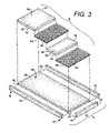
- FIG. 3 is an exploded perspective of the therapeutic mattress of FIG. 1 with the mattress cover removed;
- FIG. 4 is a side cross-sectional elevation view of the mattress through line 4 - 4 of FIG. 1 ;
- FIG. 5 is an assembled perspective view of another embodiment of a therapeutic mattress with the mattress cover partially open;
- FIGS. 6A and 6B are different embodiments of a bottom member of the therapeutic mattress and,
- FIG. 7 is an assembled perspective view of another embodiment of a therapeutic mattress with all four patient support zones made of inflatable components.
- the therapeutic mattress 10 generally comprises a covering or encasing 12 housing a first or base layer 14 and a patient support layer 16 .
- a covering or encasing 12 housing a first or base layer 14 and a patient support layer 16 .
- the various embodiments of the therapeutic mattress 10 described herein assist in preventing or decreasing the potential for such bedsores for some patients, in conjunction with proper care and nutrition.
- the therapeutic mattress 10 has a head end 18 and a foot end 20 opposing the head end 18 , a first side 22 and a second side 24 opposing the first side 24 .
- the term “head end” is used to denote the end of any referred to object that is positioned to lie nearest the head end 18 of the mattress 10
- the term “foot end” is used to denote the end of any referred to object that is positioned to lie nearest the foot end 20 of the mattress 10 .
- the therapeutic mattress 10 provides components for the various sections of the base layer 14 and patient support layer 16 of the mattress 10 that have varying levels of pressure relief and deflection as measured in units of either indentation load deflection (ILD) or pressure.
- ILD indentation load deflection
- the base layer 14 of the mattress 10 comprises a bottom member 28 and a perimetral frame.
- the perimetral frame provides support and shape to the mattress 10 and generally contains the patient support layer 16 within a defined boundary.
- the perimetral frame comprises first and second opposing transverse side panels or members 30 , 32 , and a first end member 34 . It is understood that in alternate embodiments, as discussed herein, a second end member opposing the first end member 34 may be provided to provide a perimetral frame that traverses about the entire perimeter of the mattress 10 interior of the encasing 12 .
- the bottom member 38 is preferably made of a high density, high resilient, low compression open cell urethane foam that is fire retardant and is set for medical bedding.
- the bottom member 28 is approximately 3′′ thick and has an ILD value of generally greater than 30, and preferably 40.
- the bottom member 28 in the embodiment shown extends generally from the head end 18 to the foot end 20 of the mattress 10 , and generally from the first side 22 to the second side 24 of the mattress 10 .
- the bottom member 38 may be much thinner, allowing for a thicker patient support layer 16 .
- the bottom member 28 may be comprised of a gel, fluid or other pressure compensating media, generally referred to as a non-inflatable component. Further, the bottom member 28 may be comprised of one or more inflatable and/or non-inflatable components. The bottom member 28 may also be comprised of a foam having a plurality of independently projecting foam cells.
- the bottom member 28 is a substantially flat and unitary member, as shown in FIGS. 1-5 . Alternate embodiments of the bottom member 28 are shown in FIGS. 6A and 6B . In these embodiments, the bottom member 28 may have various regions at different portions thereof. As shown in FIG. 6A , multiple transverse openings 29 are provided through the bottom member 28 to create separate zones thereof to allow more independent movement of the mattress 10 in each zone. For example, openings 29 are provided in the bottom member 29 between the head zone 31 and the seat zone 33 , between the seat zone 33 and the knee zone 35 , and between the knee zone 35 and the foot zone 37 of the bottom member 28 . More or fewer openings 29 may be provided in the bottom member 28 to accomplish the desired result.
- FIG. 6A does not intersect the perimeter of the bottom member 28 , such that the bottom member 28 remains as a unitary element, it is understood that one or more of the openings 29 could intersect the perimeter of the bottom member 28 to separate portions thereof, such as shown in FIG. 6B .
- FIG. 6B also demonstrates that the bottom member 28 may have one or more longitudinal openings 39 , including a longitudinal opening 39 that intersects a transverse opening 29 . Further, independent portions of the patient support member 16 may be provided on each of the various regions of the bottom member 28 created by the openings 29 , 39 . It is understood that the side members 30 , 32 would hold the bottom member 28 together.
- the opposing side members 30 , 32 are also preferably made of a high density, high resilient, low compression open cell urethane foam that is fire retardant and is set for medical bedding.
- the side members 30 , 32 are approximately 2′′ thick by 6.25′′ high, and they have an ILD value which is greater than the ILD value of the bottom member 18 .
- the ILD value of the side members 30 , 32 is generally greater than 40, and preferably 65.
- the side members 30 , 32 extend approximately from the head end 18 of the mattress 10 to the foot end 20 of the mattress 10 .
- the side members 30 , 32 are connected to the side edges 36 , 38 of the bottom member 28 , preferably at the contact surfaces at each side 22 , 24 , respectively, thereof.
- the first side member 30 is connected to the first side edge 36 of the bottom member 28 at the first side 22 of the bottom member 28
- the second side member 32 is connected to the second side edge 38 of the bottom member 28 at the second side 24 of the bottom member 28 .
- any conventional and commercially available adhesive which is compatible with urethane foam and suitable for medical applications may be utilized.
- the end member 34 is also preferably made of a high density, high resilient, low compression open cell urethane foam that is fire retardant and is set for medical bedding.
- the end member 34 is approximately 2′′ thick by 6.25′′ high, and it has an ILD value which is greater than the ILD value of the bottom member 28 .
- the ILD value of the end member 34 is substantially similar to the ILD value of the side members 30 , 32 , and in a most preferred embodiment the ILD value of the end member 34 is generally greater than 40, and preferably 65.
- the end member 34 is connected to an end edge 40 of the bottom member 28 at the foot end 20 thereof, and preferably at the contact surface at the foot end 20 thereof. Additionally, in the embodiments shown, the end members 34 extend approximately from the first side 22 of the mattress 10 to the second side 24 of the mattress 10 . In such embodiments a first end 42 of the end member 34 is connected to an interior surface at the foot end 20 of the first side member 30 , and a second end 44 of the end member 34 is connected to an interior surface at the foot end 20 of the second side member 32 .
- any conventional and commercially available adhesive which is compatible with urethane foam and suitable for medical applications may be utilized to secure the end member 34 to the foot end 20 of the bottom member 28 and the first and second side members 30 , 32 .
- a second end member may be provided at the head end 18 of the mattress 10 .
- This second end member would typically be secured to the head end 18 of the bottom member 28 , and the head end 18 of the first and second side members 30 , 32 , similar to the securement of the first end member 34 to the foot end 20 of the bottom member 28 .
- a cavity or well 46 that is approximately 3.25′′ deep is defined between the bottom member 28 and the opposing side members 30 , 32 and end member 34 .
- This cavity 46 is preferably utilized to house the patient support layer 16 as explained and shown herein.
- the patient support layer 16 is positioned above the base layer 14 , and the patient support layer 16 generally comprises a plurality of zones or sections to support different portions of a patient's body.
- the patient support layer 16 comprises a head zone 50 adjacent a head end 18 of the mattress 10 , a foot zone 52 adjacent the foot end 20 of the mattress 10 , a seat zone 54 adjacent the head zone 50 at the foot end thereof, and a knee zone 56 adjacent the head end of the foot zone 52 at one end and adjacent the seat zone 54 at the other end thereof.
- each zone may be utilized with the present mattress 10 , including zones which do not extend from one side of the mattress to the other side of the mattress, such as can be utilized with the bottom member 28 as shown in FIG. 6B hereof. Further, the size of each zone may vary.
- various zones or sections of the patient support layer 16 are made of a non-inflatable component 58
- different zones or sections of the patient support layer 16 are made of an inflatable or air mattress component 60
- the portion of the patient support layer 16 in the head zone 50 is made of a non-inflatable foam material component 62
- the portion of the patient support layer 16 in the seat zone 54 is made of inflatable component 64
- the portion of the patient support layer 16 in the knee zone 56 is made of a non-inflatable foam material component 66
- the portion of the patient support layer 16 in the foot zone 52 is made of an inflatable component 68 .
- the different zones or sections of the patient support layer 16 may be made entirely of inflatable components 60 or entirely of non-inflatable components.
- the patient support layer 16 is provided on the base layer 14 .
- the non-inflatable components 58 of the patient support layer 16 may be comprised of a gel, liquid fluid or some other non-inflatable pressure compensating media.
- the first foam component 62 utilized in the head zone 50 adjacent the head end 18 of the mattress 10 is a urethane memory-type foam that is fire retardant and is set for medical bedding.
- the foam component 62 for the head zone 50 has a density of between 2.0 and 6.0 lbs, and preferably at least 2.5 lbs but generally not greater than 5.0 lbs.
- the foam component 62 for the head zone 50 may be referred to as having an ILD value of between 15 and 40 ILD.
- the foam component 62 for the head zone 50 has a first side 70 adjacent the first side member 30 , and a second side 72 adjacent the second side member 32 .
- the foam component 62 in the head zone 50 is approximately 3.25′′ thick to fill the cavity or well 46 of the base layer 14 , which in one embodiment is approximately 3.25′′ deep as explained above.
- the ILD value of the foam component 62 for the head zone 50 is less than the ILD value of both the bottom member 28 and the side members 30 , 32 of the base member 14 .
- the foam component 62 for the head zone 50 is fixed, typically with an adhesive as explained above, to the base layer 14 .
- the second foam component 66 utilized in the knee zone 56 is a urethane memory-type foam that is fire retardant and is set for medical bedding.
- the foam component 66 for the knee zone 56 has a density of between 2.0 and 6.0 lbs, and preferably at least 2.5 lbs but not greater than 5.0 lbs.
- the foam component 66 for the knee zone 56 may be referred to as having an ILD value of between 15 and 40 ILD. As shown in FIG. 3 , this foam component 66 for the knee zone 56 has a first side 74 adjacent the first side member 30 , and a second side 76 adjacent the second side member 32 .
- the foam component 66 in the knee zone 56 is also approximately 3.25′′ thick to fill the cavity or well 46 of the base layer 14 .
- the ILD value of the foam component 66 for the knee zone 56 is less than the ILD value of both the bottom member 28 and the side members 30 , 32 of the base member 14 , and is typically the same as the foam component 62 for the head zone 50 .
- the foam components for the patient support layer 16 are typically less rigid than the foam components of the base layer 14 . This foam component 66 may be secured to either the base layer 14 or to the other components of the patient support layer 16 .
- a first inflatable air mattress component 68 is utilized in the foot zone 52
- a second inflatable air mattress component 64 is utilized in the seat zone 54
- additionally inflatable components 60 may also be utilized in the head zone 50 and knee zone 56 .
- the inflatable components generally comprise a plurality of low-pressure, soft, fluidly interconnected but independently movable, air-filled cells 78 which are able to redistribute air pressure between each of the cells 78 in the inflatable component to conform to the contours of a patient's body with minimal tissue deformation to provide a friction and shear relief surface.
- Such inflatable components are typically non-powered, meaning they are in a closed system.
- the air cells 78 are generally arranged in an array of rows and columns which are fluidly connected across a flexible base 80 on the inflatable components 60 .
- the air cells 78 have a substantially rectangular body that is approximately 3.5′′ high, with a top wall that has a generally pyramidal or conical shape thereto. Further, the air cells 78 have a generally square cross-sectional shape.
- the air mattress components 60 are provided in the cavity or well 46 of the base layer 14 , and extend from the first side member 30 to the second side member 32 of the base layer 14 . In one embodiment, as disclosed in FIG.
- the inflatable component 60 is positioned such that the flexible base 80 is provided adjacent the bottom member of the base layer 14 , and the air cells 78 project upwardly toward the upper encasing member 88 .
- multiple components of the inflatable component 60 may be stacked on one another at various zones of the mattress 10 .
- a first or lower inflatable component 60 may be provided on the bottom member 28 of the base layer 14
- a second or upper inflatable component 60 may be provided on the first inflatable component.
- the lower inflatable component may be orientated such that its inflatable components are positioned adjacent the bottom member 28 of the base layer 14 and its flexible base 80 is raised off the bottom member 28 .
- the upper inflatable component is layered on the lower inflatable component by placing the base layer 14 of the upper inflatable component on the base layer 14 of the lower inflatable component, and having the inflatable components of the upper inflatable component project upwardly and away from the lower inflatable component.
- the inflatable components may be utilized, such as having both the upper and lower inflatable components orientated similarly, without departing from the scope or the spirit of the present invention.
- the air cells 78 can be adjusted to the patient's body shape and size.
- the inflatable components 60 are provided in a closed system, meaning they are non-powered and require no external power source once they are inflated to the appropriate pressure. Thus, after the inflatable components 60 are inflated, they are maintained at that pressure, however, should any leakage or seepage occur they may be re-inflated to the desired pressure.
- the inflatable components 60 are made of a durable neoprene rubber that is flame-resistant and can be easily cleaned. Each of the inflatable components 60 of the different zones can be removed and replaced, if necessary. Further, the inflatable components 60 can be connected to adjacent members, including foam members, typically by snapping together, connecting with Velcro, or by some other acceptable means.
- the patient support layer 16 comprises alternating foam components 58 with inflatable components 60 .
- foam components 58 are provided in the head zone 50 and knee zone 56
- inflatable components 60 are provided in the seat zone 54 and foot zone 52 .
- inflatable components 60 are utilized to support areas of the patient's body which are most susceptible to bed sores, such as the hips/buttocks and the heels. Accordingly, inflatable components 60 having air cells 78 are provided in these zones 52 , 54 .
- the patient support layer 16 comprises a single foam component 58 in the head zone 50 , with inflatable components 60 in each of the seat zone 54 , knee zone 56 and foot zone 52 .
- Such an embodiment may be utilized with patients that need additional pressure relief in the knee zone 56 , or for patients in which the first embodiment described above is not satisfactory.
- the entire base member 14 and patient support member 16 are housed in a cavity 86 of the removable encasing 12 .
- the encasing 12 comprises a top or upper encasing member 88 and a bottom or lower encasing member 90 .
- the top encasing member 88 is connected to the bottom encasing member 90 with a connector 92 , such as a zipper 92 , generally positioned about the mid-line of the side walls 30 , 32 of the mattress 10 .
- the top encasing member 88 is made of a breathable (i.e., air permeable) stretch material that is coated with a material, such as urethane, to make it substantially impervious to water. Additionally, the material of the top encasing member 88 should be stretchy, so as not to provide unacceptable shear for the patient. In a preferred embodiment the material of the top encasing member 88 is made of a polyurethane coated nylon/spandex material. In a preferred embodiment, the stretch material is made of a 80% nylon and 20% spandex blend, such as LYCRA.
- the bottom encasing member 90 is generally made of 200 denier double-sided nylon coated urethane. Opposing parts of the zipper 92 are connected to the appropriate top and bottom encasing members 88 , 90 .
Abstract
A therapeutic mattress is providing including an encasing housing a base layer and a patient support layer in a cavity of the encasing. The base layer has a foam base member and foam side panels connected to the base member. The patient support layer is provided above the base layer and has a plurality of sections or zones. In one embodiment the plurality of sections is made of an inflatable component, and another of the plurality of sections is made of a non-inflatable component. In an alternate embodiment, each of the sections contains an inflatable component. In one embodiment, the zones of the patient support surface include a head zone adjacent a head of the mattress, a foot zone adjacent a foot end of the mattress, a seat zone adjacent the head zone, and a knee zone between the seat zone and the foot zone.
Description
This application is a continuation of U.S. patent application Ser. No. 11/349,683, filed on Feb. 8, 2006, which is a continuation-in-part of U.S. Provisional Patent Application Ser. No. 60/707,074, filed on Aug. 10, 2005, both of which applications are expressly incorporated herein by reference.
Not Applicable.
The present invention relates generally to a mattress for a hospital bed, and more specifically to a therapeutic mattress having an air composite patient support surface and a rigid perimeter.
Mattresses, including therapeutic overlays which assist in preventing bed sores, for hospital beds are well known in the art. While such mattresses and overlays according to the prior art provide a number of advantageous features, they nevertheless have certain limitations. The present invention seeks to overcome certain of these limitations and other drawbacks of the prior art, and to provide new features not heretofore available. A full discussion of the features and advantages of the present invention is deferred to the following detailed description, which proceeds with reference to the accompanying drawings.
The present invention generally provides a therapeutic mattress having a base layer, a patient support layer above the base layer, and an encasing over the base layer and the patient support layer. This therapeutic mattress is provided to assist in preventing bed sores and decreasing existing bedsores on patients.
According to one embodiment, the base layer comprises a base member, a foam end member and a plurality of foam side panels connected to the base member. The base member may be comprised of foam, gel, fluid or some other pressure compensating media. Further, the base member may be comprised of one or more inflatable and/or non-inflatable components. Generally, the side panels extend from a head end of the base member to a foot end of the base member of the mattress to create a cavity or well to support the patient support layer.
According to another embodiment, the patient support layer is provided in the well of the base layer. The patient support layer has a plurality of sections or zones. In a preferred embodiment one of the plurality of sections is made of an inflatable component, and another of the plurality of sections is made of a non-inflatable component. The non-inflatable component may also comprise a plurality of individual air cells fluidly interconnected. In one embodiment, the patient support layer comprises alternating foam portions and air cell portions. Further, in another embodiment the patient support layer comprises a first foam layer adjacent a head end of the mattress, a first air mattress portion adjacent the foot end of the mattress, a second air mattress portion adjacent the first foam layer, and a second foam layer adjacent the first air mattress portion.
According to yet another embodiment, the encasing comprises a removable cover having a cavity. Further, in a preferred embodiment the encasing comprises a lower encasing connected with a zipper to an upper encasing. In one embodiment, the upper encasing comprises a urethane coated spandex to allow the top cover to be breathable but substantially impervious to water.
Other features and advantages of the invention will be apparent from the following specification taken in conjunction with the following drawings.
To understand the present invention, it will now be described by way of example, with reference to the accompanying drawings in which:
While this invention is susceptible of embodiments in many different forms, there is shown in the drawings and will herein be described in detail preferred embodiments of the invention with the understanding that the present disclosure is to be considered as an exemplification of the principles of the invention and is not intended to limit the broad aspect of the invention to the embodiments illustrated.
Referring now to the Figures, and specifically FIGS. 1 and 5 , there are shown various embodiments of a therapeutic mattress 10. The therapeutic mattress 10 generally comprises a covering or encasing 12 housing a first or base layer 14 and a patient support layer 16. Often, patients confined to a bed for a long period of time frequently develop pressure sores, which can be known as decubitus ulcers or the more commonly referred to bedsores. The various embodiments of the therapeutic mattress 10 described herein assist in preventing or decreasing the potential for such bedsores for some patients, in conjunction with proper care and nutrition.
As shown in the Figures, the therapeutic mattress 10 has a head end 18 and a foot end 20 opposing the head end 18, a first side 22 and a second side 24 opposing the first side 24. The term “head end” is used to denote the end of any referred to object that is positioned to lie nearest the head end 18 of the mattress 10, and the term “foot end” is used to denote the end of any referred to object that is positioned to lie nearest the foot end 20 of the mattress 10. Generally, the therapeutic mattress 10 provides components for the various sections of the base layer 14 and patient support layer 16 of the mattress 10 that have varying levels of pressure relief and deflection as measured in units of either indentation load deflection (ILD) or pressure.
In one embodiment, the base layer 14 of the mattress 10 comprises a bottom member 28 and a perimetral frame. The perimetral frame provides support and shape to the mattress 10 and generally contains the patient support layer 16 within a defined boundary. In one embodiment, the perimetral frame comprises first and second opposing transverse side panels or members 30, 32, and a first end member 34. It is understood that in alternate embodiments, as discussed herein, a second end member opposing the first end member 34 may be provided to provide a perimetral frame that traverses about the entire perimeter of the mattress 10 interior of the encasing 12.
The bottom member 38 is preferably made of a high density, high resilient, low compression open cell urethane foam that is fire retardant and is set for medical bedding. In one embodiment the bottom member 28 is approximately 3″ thick and has an ILD value of generally greater than 30, and preferably 40. The bottom member 28 in the embodiment shown extends generally from the head end 18 to the foot end 20 of the mattress 10, and generally from the first side 22 to the second side 24 of the mattress 10. In alternate embodiments the bottom member 38 may be much thinner, allowing for a thicker patient support layer 16. Additionally, it is understood that instead of being comprised of foam, one or more sections or portions of the bottom member 28 may be comprised of a gel, fluid or other pressure compensating media, generally referred to as a non-inflatable component. Further, the bottom member 28 may be comprised of one or more inflatable and/or non-inflatable components. The bottom member 28 may also be comprised of a foam having a plurality of independently projecting foam cells.
In various embodiments the bottom member 28 is a substantially flat and unitary member, as shown in FIGS. 1-5 . Alternate embodiments of the bottom member 28 are shown in FIGS. 6A and 6B . In these embodiments, the bottom member 28 may have various regions at different portions thereof. As shown in FIG. 6A , multiple transverse openings 29 are provided through the bottom member 28 to create separate zones thereof to allow more independent movement of the mattress 10 in each zone. For example, openings 29 are provided in the bottom member 29 between the head zone 31 and the seat zone 33, between the seat zone 33 and the knee zone 35, and between the knee zone 35 and the foot zone 37 of the bottom member 28. More or fewer openings 29 may be provided in the bottom member 28 to accomplish the desired result. While the openings 29 shown in FIG. 6A do not intersect the perimeter of the bottom member 28, such that the bottom member 28 remains as a unitary element, it is understood that one or more of the openings 29 could intersect the perimeter of the bottom member 28 to separate portions thereof, such as shown in FIG. 6B . FIG. 6B also demonstrates that the bottom member 28 may have one or more longitudinal openings 39, including a longitudinal opening 39 that intersects a transverse opening 29. Further, independent portions of the patient support member 16 may be provided on each of the various regions of the bottom member 28 created by the openings 29, 39. It is understood that the side members 30, 32 would hold the bottom member 28 together.
As shown in FIGS. 3 and 4 , the opposing side members 30, 32 are also preferably made of a high density, high resilient, low compression open cell urethane foam that is fire retardant and is set for medical bedding. In one embodiment the side members 30, 32 are approximately 2″ thick by 6.25″ high, and they have an ILD value which is greater than the ILD value of the bottom member 18. In a preferred embodiment, the ILD value of the side members 30, 32 is generally greater than 40, and preferably 65.
In the embodiments shown, the side members 30, 32 extend approximately from the head end 18 of the mattress 10 to the foot end 20 of the mattress 10. The side members 30, 32 are connected to the side edges 36, 38 of the bottom member 28, preferably at the contact surfaces at each side 22, 24, respectively, thereof. As shown in FIG. 3 , the first side member 30 is connected to the first side edge 36 of the bottom member 28 at the first side 22 of the bottom member 28, and the second side member 32 is connected to the second side edge 38 of the bottom member 28 at the second side 24 of the bottom member 28. Preferably, any conventional and commercially available adhesive which is compatible with urethane foam and suitable for medical applications may be utilized.
Similarly, the end member 34 is also preferably made of a high density, high resilient, low compression open cell urethane foam that is fire retardant and is set for medical bedding. In one embodiment, like the side members 30, 32, the end member 34 is approximately 2″ thick by 6.25″ high, and it has an ILD value which is greater than the ILD value of the bottom member 28. Additionally, in a preferred embodiment the ILD value of the end member 34 is substantially similar to the ILD value of the side members 30, 32, and in a most preferred embodiment the ILD value of the end member 34 is generally greater than 40, and preferably 65.
As shown in FIG. 3 , the end member 34 is connected to an end edge 40 of the bottom member 28 at the foot end 20 thereof, and preferably at the contact surface at the foot end 20 thereof. Additionally, in the embodiments shown, the end members 34 extend approximately from the first side 22 of the mattress 10 to the second side 24 of the mattress 10. In such embodiments a first end 42 of the end member 34 is connected to an interior surface at the foot end 20 of the first side member 30, and a second end 44 of the end member 34 is connected to an interior surface at the foot end 20 of the second side member 32. Preferably, any conventional and commercially available adhesive which is compatible with urethane foam and suitable for medical applications may be utilized to secure the end member 34 to the foot end 20 of the bottom member 28 and the first and second side members 30, 32.
As explained above, a second end member may be provided at the head end 18 of the mattress 10. This second end member would typically be secured to the head end 18 of the bottom member 28, and the head end 18 of the first and second side members 30, 32, similar to the securement of the first end member 34 to the foot end 20 of the bottom member 28.
Because the side members 30, 32 and the end member 34 of the base are approximately 6.25″ high and the bottom member 28 is approximately 3″ high, a cavity or well 46 that is approximately 3.25″ deep is defined between the bottom member 28 and the opposing side members 30, 32 and end member 34. Alternate embodiments employing different thicknesses of the bottom member 28 and different thicknesses of the components making up the perimetral frame will have different depths of the well or cavity 46. This cavity 46 is preferably utilized to house the patient support layer 16 as explained and shown herein.
Referring to FIGS. 3 and 5 , the patient support layer 16 is positioned above the base layer 14, and the patient support layer 16 generally comprises a plurality of zones or sections to support different portions of a patient's body. For example, in the embodiments of FIGS. 3 and 5 , the patient support layer 16 comprises a head zone 50 adjacent a head end 18 of the mattress 10, a foot zone 52 adjacent the foot end 20 of the mattress 10, a seat zone 54 adjacent the head zone 50 at the foot end thereof, and a knee zone 56 adjacent the head end of the foot zone 52 at one end and adjacent the seat zone 54 at the other end thereof. It is understood, however, that a fewer number or greater number of zones of the patient support layer 16 may be utilized with the present mattress 10, including zones which do not extend from one side of the mattress to the other side of the mattress, such as can be utilized with the bottom member 28 as shown in FIG. 6B hereof. Further, the size of each zone may vary.
In preferred embodiments, various zones or sections of the patient support layer 16 are made of a non-inflatable component 58, and different zones or sections of the patient support layer 16 are made of an inflatable or air mattress component 60. For example, in the embodiment of FIGS. 2 and 3 , the portion of the patient support layer 16 in the head zone 50 is made of a non-inflatable foam material component 62, the portion of the patient support layer 16 in the seat zone 54 is made of inflatable component 64, the portion of the patient support layer 16 in the knee zone 56 is made of a non-inflatable foam material component 66, and the portion of the patient support layer 16 in the foot zone 52 is made of an inflatable component 68. Alternately, the different zones or sections of the patient support layer 16 may be made entirely of inflatable components 60 or entirely of non-inflatable components. In generally any embodiment of the patient support layer 16, however, including the embodiment of the patient support layer 16 having inflatable components 60 thereto, the patient support layer 16 is provided on the base layer 14. Instead of foam, however, the non-inflatable components 58 of the patient support layer 16 may be comprised of a gel, liquid fluid or some other non-inflatable pressure compensating media.
While different non-inflatable materials may be utilized without departing from the scope of the present invention, in one embodiment the first foam component 62 utilized in the head zone 50 adjacent the head end 18 of the mattress 10 is a urethane memory-type foam that is fire retardant and is set for medical bedding. Further, in a preferred embodiment, the foam component 62 for the head zone 50 has a density of between 2.0 and 6.0 lbs, and preferably at least 2.5 lbs but generally not greater than 5.0 lbs. Alternately, the foam component 62 for the head zone 50 may be referred to as having an ILD value of between 15 and 40 ILD. Additionally, the foam component 62 for the head zone 50 has a first side 70 adjacent the first side member 30, and a second side 72 adjacent the second side member 32. Moreover, in one embodiment the foam component 62 in the head zone 50 is approximately 3.25″ thick to fill the cavity or well 46 of the base layer 14, which in one embodiment is approximately 3.25″ deep as explained above. Preferably, the ILD value of the foam component 62 for the head zone 50 is less than the ILD value of both the bottom member 28 and the side members 30, 32 of the base member 14. In one embodiment the foam component 62 for the head zone 50 is fixed, typically with an adhesive as explained above, to the base layer 14.
Similarly, in one embodiment the second foam component 66 utilized in the knee zone 56 is a urethane memory-type foam that is fire retardant and is set for medical bedding. Further, in a preferred embodiment, the foam component 66 for the knee zone 56 has a density of between 2.0 and 6.0 lbs, and preferably at least 2.5 lbs but not greater than 5.0 lbs. Alternately, the foam component 66 for the knee zone 56 may be referred to as having an ILD value of between 15 and 40 ILD. As shown in FIG. 3 , this foam component 66 for the knee zone 56 has a first side 74 adjacent the first side member 30, and a second side 76 adjacent the second side member 32. The foam component 66 in the knee zone 56 is also approximately 3.25″ thick to fill the cavity or well 46 of the base layer 14. Finally, in a preferred embodiment the ILD value of the foam component 66 for the knee zone 56 is less than the ILD value of both the bottom member 28 and the side members 30, 32 of the base member 14, and is typically the same as the foam component 62 for the head zone 50. Further, the foam components for the patient support layer 16 are typically less rigid than the foam components of the base layer 14. This foam component 66 may be secured to either the base layer 14 or to the other components of the patient support layer 16.
In one embodiment, a first inflatable air mattress component 68 is utilized in the foot zone 52, and a second inflatable air mattress component 64 is utilized in the seat zone 54. Alternately, additionally inflatable components 60 may also be utilized in the head zone 50 and knee zone 56. In a preferred embodiment, as shown in the figures, the inflatable components generally comprise a plurality of low-pressure, soft, fluidly interconnected but independently movable, air-filled cells 78 which are able to redistribute air pressure between each of the cells 78 in the inflatable component to conform to the contours of a patient's body with minimal tissue deformation to provide a friction and shear relief surface. Such inflatable components are typically non-powered, meaning they are in a closed system. The air cells 78 are generally arranged in an array of rows and columns which are fluidly connected across a flexible base 80 on the inflatable components 60. In one embodiment, the air cells 78 have a substantially rectangular body that is approximately 3.5″ high, with a top wall that has a generally pyramidal or conical shape thereto. Further, the air cells 78 have a generally square cross-sectional shape. Generally, like the foam mattress portions 58 of the patient support member 16, the air mattress components 60 are provided in the cavity or well 46 of the base layer 14, and extend from the first side member 30 to the second side member 32 of the base layer 14. In one embodiment, as disclosed in FIG. 1 , the inflatable component 60 is positioned such that the flexible base 80 is provided adjacent the bottom member of the base layer 14, and the air cells 78 project upwardly toward the upper encasing member 88. In alternate embodiments, multiple components of the inflatable component 60 may be stacked on one another at various zones of the mattress 10. For example, in one zone a first or lower inflatable component 60 may be provided on the bottom member 28 of the base layer 14, and a second or upper inflatable component 60 may be provided on the first inflatable component. Further, the lower inflatable component may be orientated such that its inflatable components are positioned adjacent the bottom member 28 of the base layer 14 and its flexible base 80 is raised off the bottom member 28. Then, the upper inflatable component is layered on the lower inflatable component by placing the base layer 14 of the upper inflatable component on the base layer 14 of the lower inflatable component, and having the inflatable components of the upper inflatable component project upwardly and away from the lower inflatable component. One of ordinary skill in the art would readily understand that additional combinations and orientations of the inflatable components may be utilized, such as having both the upper and lower inflatable components orientated similarly, without departing from the scope or the spirit of the present invention.
The air cells 78 can be adjusted to the patient's body shape and size. In a preferred embodiment, the inflatable components 60 are provided in a closed system, meaning they are non-powered and require no external power source once they are inflated to the appropriate pressure. Thus, after the inflatable components 60 are inflated, they are maintained at that pressure, however, should any leakage or seepage occur they may be re-inflated to the desired pressure. In a preferred embodiment, the inflatable components 60 are made of a durable neoprene rubber that is flame-resistant and can be easily cleaned. Each of the inflatable components 60 of the different zones can be removed and replaced, if necessary. Further, the inflatable components 60 can be connected to adjacent members, including foam members, typically by snapping together, connecting with Velcro, or by some other acceptable means.
In the embodiment shown in FIGS. 1-4 , the patient support layer 16 comprises alternating foam components 58 with inflatable components 60. Specifically, foam components 58 are provided in the head zone 50 and knee zone 56, and inflatable components 60 are provided in the seat zone 54 and foot zone 52. Generally, inflatable components 60 are utilized to support areas of the patient's body which are most susceptible to bed sores, such as the hips/buttocks and the heels. Accordingly, inflatable components 60 having air cells 78 are provided in these zones 52, 54. Conversely, in the embodiment shown in FIG. 5 , the patient support layer 16 comprises a single foam component 58 in the head zone 50, with inflatable components 60 in each of the seat zone 54, knee zone 56 and foot zone 52. Such an embodiment may be utilized with patients that need additional pressure relief in the knee zone 56, or for patients in which the first embodiment described above is not satisfactory.
Referring now to FIGS. 1 and 4 , the entire base member 14 and patient support member 16 are housed in a cavity 86 of the removable encasing 12. Typically the encasing 12 comprises a top or upper encasing member 88 and a bottom or lower encasing member 90. The top encasing member 88 is connected to the bottom encasing member 90 with a connector 92, such as a zipper 92, generally positioned about the mid-line of the side walls 30, 32 of the mattress 10. In a preferred embodiment, the top encasing member 88 is made of a breathable (i.e., air permeable) stretch material that is coated with a material, such as urethane, to make it substantially impervious to water. Additionally, the material of the top encasing member 88 should be stretchy, so as not to provide unacceptable shear for the patient. In a preferred embodiment the material of the top encasing member 88 is made of a polyurethane coated nylon/spandex material. In a preferred embodiment, the stretch material is made of a 80% nylon and 20% spandex blend, such as LYCRA. The bottom encasing member 90, however, is generally made of 200 denier double-sided nylon coated urethane. Opposing parts of the zipper 92 are connected to the appropriate top and bottom encasing members 88, 90.
Several alternative embodiments and examples have been described and illustrated herein. A person of ordinary skill in the art would appreciate the features of the individual embodiments, and the possible combinations and variations of the components. A person of ordinary skill in the art would further appreciate that any of the embodiments could be provided in any combination with the other embodiments disclosed herein. Additionally, the terms “first,” “second,” “third,” and “fourth” as used herein are intended for illustrative purposes only and do not limit the embodiments in any way. Further, the term “plurality” as used herein indicates any number greater than one, either disjunctively or conjunctively, as necessary, up to an infinite number. Additionally, the term “having” as used herein in both the disclosure and claims, is utilized in an open-ended manner.
It will be understood that the invention may be embodied in other specific forms without departing from the spirit or central characteristics thereof. The present examples and embodiments, therefore, are to be considered in all respects as illustrative and not restrictive, and the invention is not to be limited to the details given herein. Accordingly, while the specific embodiments have been illustrated and described, numerous modifications come to mind without significantly departing from the spirit of the invention and the scope of protection is only limited by the scope of the accompanying Claims.
Claims (5)
1. A therapeutic mattress for supporting a body of a user in a prone position, comprising:
a base member having first and second opposing longitudinal foam sidewalls extending upwardly from the base member to define a well, the longitudinal foam sidewalls extending in a direction substantially parallel to a longitudinal axis of the therapeutic mattress; and,
a patient support member positioned in the well, the patient support member having a non-air cushion portion and an air cushion portion adjacent the non-air cushion portion, wherein the non-air cushion portion and the air cushion portion extend from approximately the first sidewall to the second sidewall, and wherein the air cushion portion comprises a first individually-zoned air cushion member and a second individually-zoned air cushion member, each air cushion member having a plurality of rows and columns of vertically extending, fluidly interconnected and self-equalizing air cells, the air cells being connected to a base of the air cushion member and extending vertically upward and generally perpendicular to the base of the air cushion member, the air cells further being independently moveable in a plurality of directions.
2. The therapeutic mattress of claim 1 , wherein the base member comprises a foam base member.
3. The therapeutic mattress of claim 1 , wherein the base member is connected to the sidewalls.
4. The therapeutic mattress of claim 1 , wherein the sidewalls have a height that extends from a bottom of the base member.
5. A therapeutic mattress for supporting an entire body of a user in a prone position, comprising:
a base member and first and second generally firm upstanding longitudinally extending foam side walls connected at opposing sides of the base member to define a well; and,
a patient support layer within the well, the patient support layer having a plurality of separately zoned sections, including a head zone adjacent a head end of the mattress, a foot zone adjacent a foot end of the mattress, and a seat zone between the head zone and the foot zone, wherein the patient support layer in the head zone comprises a first separate and independent non-powered air cell section extending generally from the first sidewall to the second sidewall, wherein the patient support layer in the seat zone comprises a second separate and independent non-powered air cell section extending generally from the first sidewall to the second sidewall, and wherein the patient support layer in the foot zone comprises a third separate and independent non-powered air cell section, wherein the air cell sections in each of the head, seat and foot zones are separate from the longitudinally extending side walls such that the air cell sections are free from connection to the longitudinally extending side walls to allow members of the air cell sections in each of the head zone, foot zone and seat zone to move independently from the longitudinal extending sidewalls, wherein each air cell section has a bottom wall adjacent the base member, wherein the therapeutic mattress has an overall footprint and wherein the patient support layer in each zone has a footprint that is approximately one-quarter of the overall surface area of the therapeutic mattress, wherein each air cell section is independently inflatable and deflatable with respect to the air cell sections in other zones of the mattress to independently set and adjust an air pressure of each air cell section, and wherein each air cell section comprises a plurality of individual air cell members fluidly interconnected to be self-equalizing, each of the air cell members having a sidewall extending vertically from a bottom of the air cell member and terminating in a top wall of each air cell member, each air cell having a height extending from the bottom of the air cell member to the top wall of the air cell member, and each air cell member of the air cell sections also being independently moveable in a plurality of directions, including the x, y and z directions.
Priority Applications (2)
| Application Number | Priority Date | Filing Date | Title |
|---|---|---|---|
| US11/650,737 US7509698B2 (en) | 2005-08-10 | 2007-01-08 | Therapeutic mattress |
| US12/383,326 US7716766B2 (en) | 2005-08-10 | 2009-03-23 | Therapeutic mattress |
Applications Claiming Priority (3)
| Application Number | Priority Date | Filing Date | Title |
|---|---|---|---|
| US70707405P | 2005-08-10 | 2005-08-10 | |
| US11/349,683 US7536739B2 (en) | 2005-08-10 | 2006-02-08 | Therapeutic mattress |
| US11/650,737 US7509698B2 (en) | 2005-08-10 | 2007-01-08 | Therapeutic mattress |
Related Parent Applications (1)
| Application Number | Title | Priority Date | Filing Date |
|---|---|---|---|
| US11/349,683 Continuation US7536739B2 (en) | 2005-08-10 | 2006-02-08 | Therapeutic mattress |
Related Child Applications (1)
| Application Number | Title | Priority Date | Filing Date |
|---|---|---|---|
| US12/383,326 Continuation US7716766B2 (en) | 2005-08-10 | 2009-03-23 | Therapeutic mattress |
Publications (2)
| Publication Number | Publication Date |
|---|---|
| US20070113352A1 US20070113352A1 (en) | 2007-05-24 |
| US7509698B2 true US7509698B2 (en) | 2009-03-31 |
Family
ID=37517206
Family Applications (6)
| Application Number | Title | Priority Date | Filing Date |
|---|---|---|---|
| US11/349,683 Expired - Fee Related US7536739B2 (en) | 2005-08-10 | 2006-02-08 | Therapeutic mattress |
| US11/502,633 Expired - Fee Related US7587776B2 (en) | 2005-08-10 | 2006-08-10 | Dynamic therapy bed system |
| US11/650,737 Expired - Fee Related US7509698B2 (en) | 2005-08-10 | 2007-01-08 | Therapeutic mattress |
| US12/383,326 Active US7716766B2 (en) | 2005-08-10 | 2009-03-23 | Therapeutic mattress |
| US12/584,540 Abandoned US20100000020A1 (en) | 2005-08-10 | 2009-09-08 | Dynamic therapy bed system |
| US12/833,684 Abandoned US20110163885A1 (en) | 2005-08-10 | 2010-07-09 | Adjustable therapeutic mattress |
Family Applications Before (2)
| Application Number | Title | Priority Date | Filing Date |
|---|---|---|---|
| US11/349,683 Expired - Fee Related US7536739B2 (en) | 2005-08-10 | 2006-02-08 | Therapeutic mattress |
| US11/502,633 Expired - Fee Related US7587776B2 (en) | 2005-08-10 | 2006-08-10 | Dynamic therapy bed system |
Family Applications After (3)
| Application Number | Title | Priority Date | Filing Date |
|---|---|---|---|
| US12/383,326 Active US7716766B2 (en) | 2005-08-10 | 2009-03-23 | Therapeutic mattress |
| US12/584,540 Abandoned US20100000020A1 (en) | 2005-08-10 | 2009-09-08 | Dynamic therapy bed system |
| US12/833,684 Abandoned US20110163885A1 (en) | 2005-08-10 | 2010-07-09 | Adjustable therapeutic mattress |
Country Status (4)
| Country | Link |
|---|---|
| US (6) | US7536739B2 (en) |
| EP (1) | EP1933673A2 (en) |
| CA (1) | CA2618630C (en) |
| WO (1) | WO2007021878A2 (en) |
Cited By (19)
| Publication number | Priority date | Publication date | Assignee | Title |
|---|---|---|---|---|
| US20090158528A1 (en) * | 2007-12-20 | 2009-06-25 | Wolfgang Frey | Mattress |
| US7559106B1 (en) * | 2005-12-24 | 2009-07-14 | Scott Technology Llc | Dynamic pressure relieving mattresses |
| US20090183313A1 (en) * | 2005-08-10 | 2009-07-23 | Craig Poulos | Therapeutic mattress |
| US20110191959A1 (en) * | 2004-07-28 | 2011-08-11 | Hornbach David W | Hospital bed lift and braking mechanisms |
| US20140007353A1 (en) * | 2012-04-30 | 2014-01-09 | Stryker Corporation | Patient turner |
| US20140115790A1 (en) * | 1998-05-06 | 2014-05-01 | Hill-Rom Services, Inc. | Cover system for a patient support surface |
| US8832883B2 (en) | 2010-06-12 | 2014-09-16 | American Home Health Care, Inc. | Patient support systems |
| US20150305515A1 (en) * | 2012-12-28 | 2015-10-29 | Tempur-Pedic Management, Llc | Enhanced mobility mattress |
| US20160081867A1 (en) * | 2014-09-23 | 2016-03-24 | Andrew Laurence O'Sullivan | Modular therapy mattress |
| US9433300B2 (en) | 2013-02-28 | 2016-09-06 | Hill-Rom Services, Inc. | Topper for a patient surface |
| US10238560B2 (en) | 2013-03-13 | 2019-03-26 | Hill-Rom Services, Inc. | Air fluidized therapy bed having pulmonary therapy |
| US10485357B1 (en) | 2016-04-21 | 2019-11-26 | Hickory Springs Manufacturing Company | Foam mattress with reinforced edges |
| USD912439S1 (en) * | 2018-09-04 | 2021-03-09 | Yanjie Ou | Self-contained inflatable bag sleeping pad |
| US11058226B2 (en) | 2016-12-08 | 2021-07-13 | Intex Marketing Ltd. | Recessed air pump |
| US11266554B2 (en) | 2017-09-08 | 2022-03-08 | Kreg Medical, Inc. | Bed base frame |
| US20220095806A1 (en) * | 2020-08-28 | 2022-03-31 | Avocado Green Brands, LLC | Multiple zone layered mattress |
| US11458056B2 (en) | 2014-04-18 | 2022-10-04 | Kreg Medical, Inc. | Patient support with stand-up and sit features |
| US11549514B2 (en) | 2017-11-27 | 2023-01-10 | Intex Marketing Ltd. | Manual inflation and deflation adjustment structure for a pump |
| US11668310B2 (en) | 2017-11-15 | 2023-06-06 | Intex Marketing Ltd. | Multichannel air pump |
Families Citing this family (148)
| Publication number | Priority date | Publication date | Assignee | Title |
|---|---|---|---|---|
| US7757318B2 (en) * | 2004-09-13 | 2010-07-20 | Kreg Therapeutics, Inc. | Mattress for a hospital bed |
| US20070044245A1 (en) * | 2005-09-01 | 2007-03-01 | The Spring Air Company | Mattress with triple zone topper |
| US20070226911A1 (en) * | 2006-04-03 | 2007-10-04 | Dreamwell, Ltd | Mattress or mattress pad with gel section |
| US8011045B2 (en) | 2006-06-12 | 2011-09-06 | Allen Medical Systems, Inc. | Localized patient support |
| CN101528830A (en) | 2006-07-10 | 2009-09-09 | 麦德医像公司 | Super elastic epoxy hydrogel |
| US8607387B2 (en) | 2006-11-20 | 2013-12-17 | Stryker Corporation | Multi-walled gelastic mattress system |
| US20100115702A1 (en) * | 2007-04-24 | 2010-05-13 | Biggie Lydia B | Foam and Honeycomb Mattress |
| US7971300B2 (en) * | 2007-10-09 | 2011-07-05 | Hill-Rom Services, Inc. | Air control system for therapeutic support surfaces |
| US20100325806A1 (en) * | 2007-10-09 | 2010-12-30 | Sealy Technology, Llc | Pressure dispersion support systems |
| US7845035B2 (en) * | 2007-10-09 | 2010-12-07 | Sealy Technology Llc | Pressure dispersion support systems |
| US20100205750A1 (en) * | 2007-10-12 | 2010-08-19 | Roho, Inc. | Inflatable cellular mattress with alternating zones of inflated cells |
| ITMI20072134A1 (en) * | 2007-11-07 | 2009-05-08 | Valerio Presezzi | PUTTING GREEN IN VARIABLE MORPHOLOGY FOR THE GOLF GAME. |
| ES2405106T3 (en) | 2008-02-14 | 2013-05-30 | Kingsdown, Inc. | Apparatus and methods that provide variable support and variable comfort control of a sleeping system and automatic adjustment thereof |
| EP2540194B1 (en) | 2008-02-14 | 2014-04-30 | Kingsdown, Inc. | Apparatuses and methods for evaluating a person for a sleep system |
| EP2245678A1 (en) * | 2008-02-19 | 2010-11-03 | Medipacs, Inc. | Therapeutic pressure system |
| WO2009108228A1 (en) * | 2008-02-25 | 2009-09-03 | Kingsdown, Inc. | Systems and methods for controlling a bedroom environment and for providing sleep data |
| EP2095745A1 (en) | 2008-02-26 | 2009-09-02 | Technogel Italia S.R.L. | Modular supporting element to make mattresses and the like |
| WO2009117631A2 (en) * | 2008-03-21 | 2009-09-24 | Kingsdown, Inc. | Methods and apparatuses for providing a sleep system having customized zoned support and zoned comfort |
| US8549684B2 (en) * | 2008-03-25 | 2013-10-08 | Stryker Corporation | Gelastic material having variable or same hardness and balanced, independent buckling in a mattress system |
| US7849546B2 (en) * | 2008-04-11 | 2010-12-14 | Somnium, Inc. | Membrane spring array for a mattress and a method of assembly of a membrane spring array |
| US20110179580A1 (en) * | 2008-04-11 | 2011-07-28 | Rainer Wieland | Interconnectable Grid Section for a Mattress Core |
| US8102270B2 (en) | 2008-04-25 | 2012-01-24 | Kap Medical | Patient position apparatus and method |
| US9351892B2 (en) | 2008-04-25 | 2016-05-31 | Kap Medical | Percussion therapy system, apparatus and method |
| US9867476B1 (en) * | 2008-05-15 | 2018-01-16 | Paul Bruce Thomas | Encapsulated zonal dual air and foam spring bed system with noise suppression |
| US8266747B1 (en) | 2008-06-24 | 2012-09-18 | Nomaco Inc. | Mattress side/edge support system |
| JP5474956B2 (en) * | 2008-06-26 | 2014-04-16 | キングズダウン,インコーポレイテッド | Method and apparatus for comfort / support analysis of sleep support members |
| US8144001B1 (en) * | 2008-10-07 | 2012-03-27 | D Souza Adrian J | Vibrational awakening apparatus |
| US20100175196A1 (en) * | 2008-12-17 | 2010-07-15 | Patrick Lafleche | Patient support |
| US20100170042A1 (en) * | 2009-01-08 | 2010-07-08 | Rose William H | Memory Foam Mattress and Method of Construction |
| DE102009019481A1 (en) * | 2009-05-04 | 2010-11-11 | Siemens Aktiengesellschaft | Lying device and method for supporting care of a person lying down |
| US8561236B2 (en) | 2009-06-22 | 2013-10-22 | Nomaco Inc. | Stepped-edge and side-support members, assemblies, systems, and related methods, particularly for bedding and seating |
| WO2011006093A1 (en) * | 2009-07-09 | 2011-01-13 | Kreg Medical, Inc. | Adjustable therapeutic mattress |
| JP5698745B2 (en) * | 2009-07-29 | 2015-04-08 | テクノゲル イタリア エス.アール.エル. | Modular support element |
| US8375493B2 (en) | 2009-08-27 | 2013-02-19 | Sealy Technology Llc | One piece foam mattress core encasement |
| US8646136B2 (en) | 2009-08-27 | 2014-02-11 | Nomaco Inc. | Assemblies, systems, and related methods employing interlocking components to provide at least a portion of an encasement, particularly for bedding and seating applications |
| US20110301432A1 (en) | 2010-06-07 | 2011-12-08 | Riley Carl W | Apparatus for supporting and monitoring a person |
| US8525679B2 (en) | 2009-09-18 | 2013-09-03 | Hill-Rom Services, Inc. | Sensor control for apparatuses for supporting and monitoring a person |
| US8531307B2 (en) * | 2009-09-18 | 2013-09-10 | Hill-Rom Services, Inc. | Patient support surface index control |
| US9420895B2 (en) | 2009-12-17 | 2016-08-23 | Stryker Corporation | Patient support |
| US8856992B2 (en) | 2010-02-05 | 2014-10-14 | Stryker Corporation | Patient/invalid handling support |
| IT1398021B1 (en) * | 2010-02-12 | 2013-02-07 | Plebani | DEVICE FOR MASSAGE OR HANDLING OF THE HUMAN BODY. |
| WO2011105747A2 (en) * | 2010-02-24 | 2011-09-01 | (주)세라젬에어텍 | Air mattress, air mattress manufacturing device and method |
| US8555441B2 (en) * | 2010-04-14 | 2013-10-15 | Star Cushion Products, Inc. | Therapeutic mattress system and methods of fabricating same |
| USD677097S1 (en) * | 2010-05-06 | 2013-03-05 | Nomaco, Inc. | Slotted side support |
| US8793821B2 (en) | 2010-07-12 | 2014-08-05 | Doug Fowkes | Cushion with double stacked off-set honeycomb |
| USD694554S1 (en) | 2010-08-17 | 2013-12-03 | Nomaco Inc. | Side support |
| USD695550S1 (en) | 2010-08-17 | 2013-12-17 | Nomaca Inc. | Side support |
| USD694042S1 (en) | 2010-08-17 | 2013-11-26 | Nomaco Inc. | Side support |
| USD692689S1 (en) | 2010-08-17 | 2013-11-05 | Nomaco Inc. | Side support |
| US8512843B2 (en) * | 2010-09-17 | 2013-08-20 | Richard B. Villata | Composite matrix and gel padding and method of manufacturing |
| GB201017183D0 (en) * | 2010-10-12 | 2010-11-24 | Katan Joseph M | Body support platform |
| EP2627220A4 (en) * | 2010-10-14 | 2014-05-28 | Star Cushion Products Inc | Methods and apparatus for fabricating cellular cushions |
| EP2731567B1 (en) | 2011-07-13 | 2016-12-14 | Stryker Corporation | Patient/invalid handling support |
| JP5703160B2 (en) * | 2011-07-28 | 2015-04-15 | 住友理工株式会社 | mattress |
| JP5780643B2 (en) * | 2011-07-28 | 2015-09-16 | 住友理工株式会社 | mattress |
| USD673801S1 (en) | 2011-08-03 | 2013-01-08 | Nomaco Inc. | Mattress bed encasement |
| USD673800S1 (en) | 2011-08-03 | 2013-01-08 | Nomaco Inc. | Mattress bed encasement |
| US20130038724A1 (en) * | 2011-08-08 | 2013-02-14 | Robert Bosch Gmbh | Camera tilt flex loop for high frequency signals |
| USD675051S1 (en) | 2011-09-30 | 2013-01-29 | Nomaco Inc. | Edge support cushion |
| ES2588380T3 (en) * | 2011-11-11 | 2016-11-02 | Skydex Technologies, Inc. | Cell cushion |
| EP2804572B1 (en) * | 2012-01-17 | 2020-03-25 | Stryker Corporation | Patient/invalid support with pressure reducing system |
| USD691400S1 (en) | 2012-02-10 | 2013-10-15 | Nomaco Inc. | Stackable base for mattress assembly |
| CA2906274A1 (en) | 2012-03-14 | 2013-09-19 | Medipacs, Inc. | Smart polymer materials with excess reactive molecules |
| US20130291311A1 (en) * | 2012-05-02 | 2013-11-07 | Yu-Chieh Wang | Ventilating Pad With Buffer And Elastic Support |
| JP6261879B2 (en) | 2012-05-22 | 2018-01-17 | ヒル−ロム サービシズ,インコーポレイテッド | User bed prediction system, method and apparatus |
| US9861550B2 (en) | 2012-05-22 | 2018-01-09 | Hill-Rom Services, Inc. | Adverse condition detection, assessment, and response systems, methods and devices |
| JP6017686B2 (en) * | 2012-06-21 | 2016-11-02 | ヒル−ロム サービシズ,インコーポレイテッド | Patient holding system and method of use |
| USD697337S1 (en) | 2012-07-03 | 2014-01-14 | Nomaco, Inc. | Stackable base for mattress assembly |
| US20140026326A1 (en) * | 2012-07-25 | 2014-01-30 | Richard N. Codos | Pressure adjustable platform system |
| CN102743266A (en) * | 2012-08-01 | 2012-10-24 | 卫美恒(苏州)医疗器械有限公司 | Local-height-adjustable pressure reduction seat cushion |
| US8973193B2 (en) * | 2012-08-08 | 2015-03-10 | Richard N. Codos | Methods of optimizing a pressure contour of a pressure adjustable platform system |
| EP3284451A1 (en) * | 2012-08-29 | 2018-02-21 | Hill-Rom Services, Inc. | Occupant support with longitudinally spaced turn assist members or with longitudinally distributed, independently operable turn assist members, associated graphical user interface, and methods of providing access to portions of the occupant support or to occupants thereof |
| EP3789002A1 (en) * | 2012-09-05 | 2021-03-10 | Stryker Corporation | Patient support |
| US20140223666A1 (en) * | 2013-02-04 | 2014-08-14 | David R. Pavlin | Skin irritant reduction cushioning construction |
| US9333136B2 (en) | 2013-02-28 | 2016-05-10 | Hill-Rom Services, Inc. | Sensors in a mattress cover |
| CN109288502B (en) | 2013-03-14 | 2022-06-21 | 数眠公司 | Inflatable air mattress snore detection and response |
| WO2014151854A1 (en) | 2013-03-14 | 2014-09-25 | Nunn Rob | Inflatable air mattress autofill and off bed pressure adjustment |
| EP2967226B1 (en) | 2013-03-14 | 2018-06-27 | Select Comfort Corporation | Inflatable air mattress alert and monitoring system |
| AU2014236557B2 (en) * | 2013-03-14 | 2016-10-06 | Sleep Number Corporation | Inflatable air mattress system architecture |
| CN103239339B (en) * | 2013-04-19 | 2016-02-17 | 广州军区广州总医院 | A kind of general anesthesia prone position head support device |
| US9339117B1 (en) * | 2013-05-24 | 2016-05-17 | Hickory Springs Manufacturing Company | Mattress with a visco elastic polyurethane foam layer |
| GB2515572A (en) * | 2013-06-28 | 2014-12-31 | Balluga Ltd | Body support unit and related components |
| USD737074S1 (en) | 2013-07-03 | 2015-08-25 | Nomaco Inc. | Foam cushion base |
| USD740053S1 (en) | 2013-07-03 | 2015-10-06 | Nomaco Inc. | Foam cushion base |
| EP3019369A1 (en) * | 2013-07-09 | 2016-05-18 | Simon Dickinson | Improvements to structure to resist impact |
| NL2011216C2 (en) * | 2013-07-25 | 2015-01-27 | Decupr B V | ANTI-THREADED MATTRESS WITH AIR ROOMS. |
| US9782312B2 (en) | 2013-09-05 | 2017-10-10 | Stryker Corporation | Patient support |
| EP2870954B1 (en) * | 2013-11-06 | 2016-06-15 | KH LLoreda, S.A. | Adaptive inflatable cushion |
| US10064744B2 (en) | 2013-12-26 | 2018-09-04 | The Board Of Regents Of The University Of Texas System | Fluid-driven bubble actuator arrays |
| US9997089B2 (en) | 2013-12-31 | 2018-06-12 | Tempur-Pedic Management, Llc | Cover assemblies for mattresses |
| US9675189B2 (en) * | 2013-12-31 | 2017-06-13 | Tempur-Pedic Management, Llc | Cover assemblies for mattresses |
| US9601034B2 (en) * | 2013-12-31 | 2017-03-21 | Tempur-Pedic Management, Llc | Cover assemblies for mattresses |
| US9888785B2 (en) | 2014-04-21 | 2018-02-13 | Casper Sleep Inc. | Mattress |
| JP2017522166A (en) * | 2014-07-25 | 2017-08-10 | ハントレイ テクノロジー リミテッドHuntleigh Technology Limited | Medical mattress with low volume bladder |
| USD780704S1 (en) * | 2014-08-27 | 2017-03-07 | Mitsubishi Electric Corporation | Light source module |
| US10182954B2 (en) | 2014-09-08 | 2019-01-22 | Wcw, Inc. | Cushioning device and method |
| US9078795B1 (en) | 2014-09-08 | 2015-07-14 | Wcw, Inc. | Cushioning device and method of cushioning a body |
| USD768584S1 (en) * | 2014-11-13 | 2016-10-11 | Mitsubishi Electric Corporation | Light source module |
| WO2016112023A1 (en) | 2015-01-05 | 2016-07-14 | Select Comfort Corporation | Bed with user occupancy tracking |
| US10912701B2 (en) | 2015-01-07 | 2021-02-09 | The Board Of Regents Of The University Of Texas System | Fluid-driven actuators and related methods |
| US20160338499A1 (en) * | 2015-05-21 | 2016-11-24 | Global Medical Foam, Inc. | Customizable Pressure Offloading Cushioning Device |
| US11311438B2 (en) | 2015-05-21 | 2022-04-26 | Global Medical Foam, Inc. | Customizable pressure offloading cushioning device |
| JP6730327B2 (en) * | 2015-05-29 | 2020-07-29 | ヒル−ロム サービシズ,インコーポレイテッド | Patient support device |
| US11737934B2 (en) | 2015-10-14 | 2023-08-29 | Qfix Systems, Llc | MRI compatible patient trolley |
| EP3362020B1 (en) | 2015-10-14 | 2022-01-12 | Qfix Systems, LLC | Imaging system comprising mri compatible patient trolley |
| US10986936B2 (en) * | 2016-10-06 | 2021-04-27 | Skydex Technologies, Inc. | Tiered void cells |
| WO2018098463A1 (en) | 2016-11-28 | 2018-05-31 | The Board Of Regents Of The University Of Texas System | Dual-layer insole apparatuses for diabetic foot lesion prevention and related methods |
| WO2018102684A1 (en) | 2016-12-01 | 2018-06-07 | The Board Of Regent Of The University Of Texas System | Variable stiffness apparatuses using an interconnected dual layer fluid-filled cell array |
| US11172892B2 (en) | 2017-01-04 | 2021-11-16 | Hill-Rom Services, Inc. | Patient support apparatus having vital signs monitoring and alerting |
| CN106580650A (en) * | 2017-01-23 | 2017-04-26 | 惠州金桔家具有限公司 | Expansion pad massage device |
| EP3612057A4 (en) | 2017-04-20 | 2021-02-17 | The Board of Regents of The University of Texas System | Pressure modulating soft actuator array devices and related systems and methods |
| FR3065863B1 (en) * | 2017-05-02 | 2019-07-05 | Caroline COLBEAU-JUSTIN | INFLATABLE COMPENSATION MODULE FOR MATTRESSES, MODULAR |
| US11116326B2 (en) | 2017-08-14 | 2021-09-14 | Casper Sleep Inc. | Mattress containing ergonomic and firmness-regulating endoskeleton |
| SE1751336A1 (en) | 2017-10-27 | 2018-12-27 | Care Of Sweden Ab | System and mattress for preventing pressure wounds |
| US11246775B2 (en) | 2017-12-28 | 2022-02-15 | Stryker Corporation | Patient turning device for a patient support apparatus |
| US11173085B2 (en) | 2017-12-28 | 2021-11-16 | Stryker Corporation | Mattress cover for a mattress providing rotation therapy to a patient |
| US11737938B2 (en) | 2017-12-28 | 2023-08-29 | Sleep Number Corporation | Snore sensing bed |
| USD912438S1 (en) * | 2018-01-10 | 2021-03-09 | EcoTek Outdoors, LLC | Inflatable sleeping pad |
| WO2019183502A1 (en) | 2018-03-22 | 2019-09-26 | Bussert Research Inc. | Therapeutic seat cushion equipped for pressure monitoring and inflation system for same |
| KR102047844B1 (en) * | 2018-04-16 | 2019-11-22 | 주식회사 엔에스비에스 | Air Cushion Block Structure, Mattress Installed with Air Cushion Block Structure Therein |
| US11241100B2 (en) | 2018-04-23 | 2022-02-08 | Casper Sleep Inc. | Temperature-regulating mattress |
| USD879966S1 (en) | 2018-09-28 | 2020-03-31 | Stryker Corporation | Crib assembly |
| USD977109S1 (en) * | 2018-09-28 | 2023-01-31 | Stryker Corporation | Crib assembly for a patient support |
| US11241349B2 (en) | 2018-09-28 | 2022-02-08 | Stryker Corporation | Patient support including a connector assembly |
| USD901940S1 (en) | 2018-09-28 | 2020-11-17 | Stryker Corporation | Patient support |
| USD888962S1 (en) | 2018-09-28 | 2020-06-30 | Stryker Corporation | Cover assembly for a patient support |
| US11219567B2 (en) | 2018-09-28 | 2022-01-11 | Stryker Corporation | Patient support |
| USD888964S1 (en) | 2018-09-28 | 2020-06-30 | Stryker Corporation | Crib assembly for a patient support |
| USD888963S1 (en) | 2018-09-28 | 2020-06-30 | Stryker Corporation | Cover assembly for a patient support |
| USD877915S1 (en) | 2018-09-28 | 2020-03-10 | Stryker Corporation | Crib assembly |
| USD894957S1 (en) | 2018-10-31 | 2020-09-01 | Stryker Corporation | Display screen or portion thereof with graphical user interface |
| USD890914S1 (en) | 2018-10-31 | 2020-07-21 | Stryker Corporation | Pump |
| USD894956S1 (en) | 2018-10-31 | 2020-09-01 | Stryker Corporation | Display screen or portion thereof with graphical user interface |
| USD893543S1 (en) | 2018-10-31 | 2020-08-18 | Stryker Corporation | Display screen with graphical user interface |
| USD894223S1 (en) | 2018-10-31 | 2020-08-25 | Stryker Corporation | Display screen with animated graphical user interface |
| USD892159S1 (en) | 2018-10-31 | 2020-08-04 | Stryker Corporation | Display screen with animated graphical user interface |
| USD894226S1 (en) | 2018-10-31 | 2020-08-25 | Stryker Corporation | Display screen or portion thereof with graphical user interface |
| US11559451B2 (en) | 2018-10-31 | 2023-01-24 | Stryker Corporation | Fluid source for supplying fluid to therapy devices |
| CN109481184B (en) * | 2018-12-29 | 2023-10-27 | 广州医软智能科技有限公司 | Intensive care sickbed with back beating function and control method thereof |
| US10883648B2 (en) * | 2019-02-25 | 2021-01-05 | International Business Machines Corporation | Leveling and stabilization of weight biased loads |
| US10765219B1 (en) * | 2019-04-17 | 2020-09-08 | Ka Group Ag | Lounger having a pneumatic lounging system |
| WO2021026440A1 (en) * | 2019-08-08 | 2021-02-11 | Simbex Llc | System for providing fluid to a distributed network of chambers |
| USD908398S1 (en) | 2019-08-27 | 2021-01-26 | Casper Sleep Inc. | Mattress |
| CN110507496A (en) * | 2019-09-06 | 2019-11-29 | 上海创始实业(集团)有限公司 | Air bag pad assembly, intelligent pressure sore prevention seat cushion and monitor system |
| USD927889S1 (en) | 2019-10-16 | 2021-08-17 | Casper Sleep Inc. | Mattress layer |
| USD917933S1 (en) * | 2019-12-18 | 2021-05-04 | Camco Manufacturing, Inc. | Bed spring |
| US11877844B2 (en) * | 2020-02-19 | 2024-01-23 | Hill-Rom Services, Inc. | Respiration detection using radar |
| CN113350155B (en) * | 2021-07-12 | 2022-06-17 | 常州市第一人民医院 | Back strap type back beater |
Citations (88)
| Publication number | Priority date | Publication date | Assignee | Title |
|---|---|---|---|---|
| US3394415A (en) | 1966-04-06 | 1968-07-30 | Buster A. Parker | Pressure pad with independent cells |
| US3605145A (en) | 1968-12-05 | 1971-09-20 | Robert H Graebe | Body support |
| US3701173A (en) | 1970-05-22 | 1972-10-31 | John K Whitney | Inflatable body support |
| US3872525A (en) * | 1972-01-10 | 1975-03-25 | James M Lea | Inflatable foam pad |
| US4042988A (en) * | 1976-11-02 | 1977-08-23 | Odell Holliday | Air mattress |
| US4224706A (en) * | 1978-10-16 | 1980-09-30 | Dial-A-Firm, Inc. | Pneumatic bed |
| US4391009A (en) | 1980-10-17 | 1983-07-05 | Huntleigh Medical Ltd. | Ventilated body support |
| US4449261A (en) * | 1981-06-22 | 1984-05-22 | Simmons U.S.A. Corp. | Bed mattress having an improved pillow top |
| US4686725A (en) | 1985-10-28 | 1987-08-18 | Span America Medical Systems | Mattress cushion with securement feature |
| US4706313A (en) | 1986-05-01 | 1987-11-17 | Comfortex, Inc. | Decubitus ulcer mattress |
| US4897890A (en) | 1983-01-05 | 1990-02-06 | Walker Robert A | Air control system for air bed |
| US4901387A (en) | 1988-03-21 | 1990-02-20 | Luke John K | Mattress overlay with individual foam springs |
| US4947500A (en) * | 1988-08-25 | 1990-08-14 | OBA AG and Hans Vollmin | Therapeutic mattress, in particular for preventing or curing decubitus ulcers |
| US4949414A (en) | 1989-03-09 | 1990-08-21 | Ssi Medical Services, Inc. | Modular low air loss patient support system and methods for automatic patient turning and pressure point relief |
| US4977629A (en) | 1988-03-15 | 1990-12-18 | Jones Betty J | Portable inflatable patient assist apparatus |
| US4986738A (en) | 1988-10-12 | 1991-01-22 | Leggett & Platt Incorporated | Airflow control system pump and housing |
| US5025519A (en) | 1986-10-22 | 1991-06-25 | Span-America Medical Systems, Inc. | Multi-section mattress overlay for systematized pressure dispersion |
| US5031261A (en) | 1990-03-15 | 1991-07-16 | E. R. Carpenter Company, Inc. | Mattress overlay for avoidance of decubitus ulcers |
| US5039158A (en) | 1990-03-15 | 1991-08-13 | Edmund Maier | Seating cushion |
| US5070560A (en) | 1990-10-22 | 1991-12-10 | Healthflex, Inc. | Pressure relief support system for a mattress |
| US5107558A (en) | 1990-07-11 | 1992-04-28 | Lueck Werner | Mattress with removable insert |
| US5109560A (en) | 1991-09-18 | 1992-05-05 | Keisei Medical Industrial Co., Ltd. | Ventilated air mattress with alternately inflatable air cells having communicating upper and lower air chambers |
| US5117521A (en) | 1990-05-16 | 1992-06-02 | Hill-Rom Company, Inc. | Care cart and transport system |
| US5121513A (en) | 1989-03-09 | 1992-06-16 | Ssi Medical Services, Inc. | Air sack support manifold |
| US5129115A (en) | 1988-10-12 | 1992-07-14 | L&P Property Management Company | Method of prefilling and supporting person on fluid filled body support system |
| US5163196A (en) | 1990-11-01 | 1992-11-17 | Roho, Inc. | Zoned cellular cushion with flexible flaps containing inflating manifold |
| US5179742A (en) | 1991-11-01 | 1993-01-19 | Stryker Corporation | Pressure reduction mattress |
| US5182826A (en) | 1989-03-09 | 1993-02-02 | Ssi Medical Services, Inc. | Method of blower control |
| US5233974A (en) | 1990-09-25 | 1993-08-10 | Matsushita Electric Works, Ltd. | Air massaging apparatus with a series of sequentially inflating air bags |
| US5243721A (en) | 1991-08-16 | 1993-09-14 | Karomed Limited | Inflatable mattress and air supply with changeover valve |
| US5249319A (en) | 1992-09-09 | 1993-10-05 | Mellen Air Manufacturing, Inc. | Low air loss, pressure relieving mattress system |
| US5259079A (en) * | 1992-10-26 | 1993-11-09 | Big Sur Waterbeds, Inc. | Double bed arrangement with combination mattress |
| US5325551A (en) | 1992-06-16 | 1994-07-05 | Stryker Corporation | Mattress for retarding development of decubitus ulcers |
| US5335651A (en) | 1990-05-16 | 1994-08-09 | Hill-Rom Company, Inc. | Ventilator and care cart each capable of nesting within and docking with a hospital bed base |
| US5337845A (en) | 1990-05-16 | 1994-08-16 | Hill-Rom Company, Inc. | Ventilator, care cart and motorized transport each capable of nesting within and docking with a hospital bed base |
| US5370111A (en) | 1990-05-16 | 1994-12-06 | Hill-Rom Company, Inc. | Mobile ventilator capable of nesting within and docking with a hospital bed base |
| USD355322S (en) | 1993-12-03 | 1995-02-14 | Span-America Medical Systems, Inc. | Tri-zone mattress overlay |
| US5398354A (en) | 1993-07-07 | 1995-03-21 | B. G. Industries, Inc. | Heel pillow mattress |
| US5425148A (en) | 1993-10-20 | 1995-06-20 | Ss1 Medical Services, Inc. | Convertible footboard for a patient support |
| US5454142A (en) | 1992-12-31 | 1995-10-03 | Hoechst Celanese Corporation | Nonwoven fabric having elastometric and foam-like compressibility and resilience and process therefor |
| US5461741A (en) | 1992-02-20 | 1995-10-31 | Graebe; Robert H. | Modular cushion construction with foamed base |
| US5479666A (en) | 1994-01-25 | 1996-01-02 | Hill-Rom Company, Inc. | Foot egress chair bed |
| US5483709A (en) | 1994-04-01 | 1996-01-16 | Hill-Rom Company, Inc. | Low air loss mattress with rigid internal bladder and lower air pallet |
| US5513406A (en) | 1994-04-21 | 1996-05-07 | Hill-Rom Company, Inc. | Modular hospital bed and method of patient handling |
| US5551107A (en) * | 1992-02-20 | 1996-09-03 | Graebe; Robert H. | Modular cushion construction with detachable pommel, having a cover with front and rear openings |
| US5568660A (en) * | 1992-06-24 | 1996-10-29 | Span-America Medical Systems, Inc. | Wheelchair cushion and cover |
| US5577279A (en) | 1990-05-16 | 1996-11-26 | Hill-Rom Company, Inc. | Hospital bed |
| US5586346A (en) | 1994-02-15 | 1996-12-24 | Support Systems, International | Method and apparatus for supporting and for supplying therapy to a patient |
| US5596781A (en) | 1992-02-20 | 1997-01-28 | Crown Therapeutics, Inc. | Vacuum/heat formed cushion with pyramidal, inflatable cells |
| US5606754A (en) | 1989-03-09 | 1997-03-04 | Ssi Medical Services, Inc. | Vibratory patient support system |
| US5611096A (en) | 1994-05-09 | 1997-03-18 | Kinetic Concepts, Inc. | Positional feedback system for medical mattress systems |
| US5613255A (en) | 1994-12-27 | 1997-03-25 | Hill-Rom, Inc. | Hospital bed having scissors lifting apparatus |
| US5630238A (en) | 1995-08-04 | 1997-05-20 | Hill-Rom, Inc. | Bed with a plurality of air therapy devices, having control modules and an electrical communication network |
| US5634224A (en) | 1994-08-16 | 1997-06-03 | Gates; Stephen M. | Inflatable cushioning device with self opening intake valve |
| US5642546A (en) | 1995-09-19 | 1997-07-01 | Select Comfort Corporation | Inflatable mattress with improved border support wall |
| US5649331A (en) | 1994-06-03 | 1997-07-22 | Span-America Medical Systems, Inc. | Self-adjusting pressure relief support system and methodology |
| US5666681A (en) | 1995-01-03 | 1997-09-16 | Hill-Rom, Inc. | Heel pressure management apparatus and method |
| US5672849A (en) | 1994-03-31 | 1997-09-30 | Hill-Rom Company, Inc. | Patient weigh scale |
| US5680661A (en) | 1990-05-16 | 1997-10-28 | Hill-Rom, Inc. | Hospital bed with user care apparatus |
| US5689845A (en) | 1996-04-17 | 1997-11-25 | Roho, Inc. | Expansible air cell cushion |
| US5715548A (en) | 1994-01-25 | 1998-02-10 | Hill-Rom, Inc. | Chair bed |
| US5731062A (en) | 1995-12-22 | 1998-03-24 | Hoechst Celanese Corp | Thermoplastic three-dimensional fiber network |
| US5845352A (en) | 1996-07-12 | 1998-12-08 | Roho, Inc. | Foam-air hybrid cushion and method of making same |
| US5963998A (en) | 1994-11-08 | 1999-10-12 | Racing Strollers, Inc. | Recessed sleeping surface |
| US5987668A (en) | 1997-09-15 | 1999-11-23 | Span-America Medical Systems, Inc. | Fabric covered mattress pad |
| US6047424A (en) | 1995-08-04 | 2000-04-11 | Hill-Rom, Inc. | Bed having modular therapy devices |
| US6119291A (en) | 1995-08-04 | 2000-09-19 | Hill-Rom, Inc. | Percussion and vibration therapy apparatus |
| US6212714B1 (en) | 1995-01-03 | 2001-04-10 | Hill-Rom, Inc. | Hospital bed and mattress having a retracting foot section |
| US6223369B1 (en) | 1997-11-14 | 2001-05-01 | Span-America Medical Systems, Inc. | Patient support surfaces |
| US6256822B1 (en) | 1999-01-29 | 2001-07-10 | Span-America Medical Systems, Inc. | Patient support system with side bolster features |
| US6256821B1 (en) | 1998-07-14 | 2001-07-10 | Dennis Boyd | Mattress system |
| US6269504B1 (en) | 1998-05-06 | 2001-08-07 | Hill-Rom Services, Inc. | Mattress or cushion structure |
| US6269505B1 (en) | 1999-04-20 | 2001-08-07 | M.P.L. Ltd. | Inflatable cushioning device with manifold system |
| US6286166B1 (en) | 1998-06-19 | 2001-09-11 | Hill-Rom Services, Inc. | Modular foam mattress |
| US6324709B1 (en) | 1998-07-31 | 2001-12-04 | France Bed Co., Ltd. | Mattress apparatus and bed apparatus |
| US6374436B1 (en) | 1994-01-25 | 2002-04-23 | Hill-Rom Services, Inc. | Hospital bed |
| US6446283B1 (en) | 1999-01-22 | 2002-09-10 | Hill-Rom Services, Inc. | Convertible stretcher |
| US6481033B2 (en) * | 1998-09-25 | 2002-11-19 | Isaac Fogel | Multiple module mattress system with depressions accomodating inserts of differing firmness |
| US6499167B1 (en) | 1995-08-04 | 2002-12-31 | Hill-Rom Services, Inc. | Mattress section support |
| US6536056B1 (en) | 1996-11-18 | 2003-03-25 | John H. Vrzalik | Bariatric treatment system and related methods |
| US6560793B2 (en) | 1999-09-09 | 2003-05-13 | Lucinda B. Walker | Single attendant patient repositioning and care device |
| US6584628B1 (en) | 1995-08-04 | 2003-07-01 | Hill-Rom Services, Inc. | Hospital bed having a rotational therapy device |
| US6601253B1 (en) | 2002-07-08 | 2003-08-05 | Peter Tarquinio | Multilayer foam mattress with side supports |
| US6611979B2 (en) | 1997-09-23 | 2003-09-02 | Hill-Rom Services, Inc. | Mattress having a retractable foot section |
| US6623080B2 (en) | 2001-08-09 | 2003-09-23 | Roho, Inc. | Cellular cushion vehicle seat system |
| US6662393B2 (en) | 2002-03-19 | 2003-12-16 | Dennis Boyd | Composite mattress |
| US7120950B2 (en) * | 2004-07-20 | 2006-10-17 | Goodway Industrial (H.K.) Ltd. | Hybrid mattress |
| US7188379B2 (en) * | 2005-02-15 | 2007-03-13 | L & P Property Management Company | Combination air and spring mattress for a sofa sleeper |
Family Cites Families (56)
| Publication number | Priority date | Publication date | Assignee | Title |
|---|---|---|---|---|
| US533974A (en) * | 1895-02-12 | Or coating machine | ||
| US1772310A (en) * | 1926-12-16 | 1930-08-05 | Julian D Hart | Variable-pressure bed or mattress |
| GB1341325A (en) * | 1971-07-09 | 1973-12-19 | Scales J T | Inflatable support appliance |
| DE8610640U1 (en) | 1986-04-18 | 1986-06-26 | Forgber, Hans-Jürgen, 4535 Westerkappeln | mattress |
| DE3729245A1 (en) | 1987-05-14 | 1988-12-01 | Rokado Metall Holz Kunststoff | MATTRESS MADE OF AN ELASTIC PLASTIC MATERIAL |
| US4852195A (en) * | 1987-10-16 | 1989-08-01 | Schulman David A | Fluid pressurized cushion |
| AU615543B2 (en) * | 1988-03-23 | 1991-10-03 | Robert Ferrand | Patient support system |
| US4864671A (en) * | 1988-03-28 | 1989-09-12 | Decubitus, Inc. | Controllably inflatable cushion |
| US4868725A (en) * | 1988-10-31 | 1989-09-19 | Koito Manufacturing Co., Ltd. | Motor vehicle combination lamp |
| CA1331889C (en) | 1989-09-19 | 1994-09-06 | Bruno H. Walter | Bed mattress or the like |
| EP0548918B1 (en) * | 1991-12-25 | 1999-03-17 | Mitsubishi Chemical Corporation | Pitch-based carbon fibers and process for their production |
| EP0661733A2 (en) * | 1993-12-21 | 1995-07-05 | International Business Machines Corporation | One dimensional silicon quantum wire devices and the method of manufacture thereof |
| US6892405B1 (en) | 1994-05-09 | 2005-05-17 | Kci Licensing, Inc. | Therapeutic bed and related apparatus and methods |
| US5493742A (en) * | 1994-05-10 | 1996-02-27 | Lake Medical Products, Inc. | Ventilating air mattress with an inflating quilted pad |
| US5641425A (en) * | 1994-09-08 | 1997-06-24 | Multiform Desiccants, Inc. | Oxygen absorbing composition |
| JPH08101018A (en) * | 1994-09-30 | 1996-04-16 | Sintokogio Ltd | Method for measuring dimension of mold and mold-related parts by using laser length measuring instrument |
| US7017208B2 (en) | 1995-08-04 | 2006-03-28 | Hill-Rom Services, Inc. | Hospital bed |
| WO1997008002A1 (en) * | 1995-08-25 | 1997-03-06 | Kabushiki Kaisha Toyoda Jidoshokki Seisakusho | Viscous heater |
| US6928681B1 (en) | 1995-11-23 | 2005-08-16 | Kci Licensing, Inc. | Alternating pressure pads |
| US6115861A (en) * | 1997-10-09 | 2000-09-12 | Patmark Company, Inc. | Mattress structure |
| US6018832A (en) | 1996-07-31 | 2000-02-01 | Graebe; Robert H. | Wraparound orthotic base composite adjustable cushion using same and method of measuring fit of the adjusted cushion to the user's shape |
| US7346945B2 (en) | 1996-11-18 | 2008-03-25 | Kci Licensing, Inc. | Bariatric treatment system and related methods |
| US6745996B1 (en) | 1997-07-28 | 2004-06-08 | Gaymar Industries, Inc. | Alternating pressure valve system |
| US6021533A (en) | 1997-08-25 | 2000-02-08 | Hill-Rom, Inc. | Mattress apparatus having a siderail down sensor |
| US7191482B2 (en) | 1998-05-06 | 2007-03-20 | Hill Rom Services, Inc. | Patient support |
| FR2798833B1 (en) | 1999-09-24 | 2001-11-23 | Medidev R Care Sa | ADJUSTABLE LOW PRESSURE MATTRESS DEVICE |
| US6442780B1 (en) | 2000-03-09 | 2002-09-03 | Kci Licensing, Inc. | Mattress with semi-independent pressure relieving pillars |
| CA2596504C (en) | 2000-05-17 | 2011-07-26 | Robert B. Chaffee | Inflatable device with recessed fluid controller and modified adjustment device |
| CA2353208C (en) | 2000-07-18 | 2010-12-14 | Span-America Medical Systems, Inc. | Air-powered low interface pressure support surface |
| GB2370452B (en) * | 2000-12-19 | 2004-10-20 | Inmarsat Ltd | Communication method and apparatus |
| US6687936B2 (en) | 2001-01-18 | 2004-02-10 | Roho, Inc. | Valve for zoned cellular cushion |
| US6922863B2 (en) | 2001-03-07 | 2005-08-02 | Gualtiero G. Giori | Adjustable foam mattress |
| US6698046B1 (en) | 2001-03-26 | 2004-03-02 | Sunflower Medical, L.L.C. | Air mattress control unit |
| US6990700B2 (en) | 2001-06-22 | 2006-01-31 | Team Worldwide Corporation | Inflatable product provided with electric air pump |
| DE10236363A1 (en) | 2001-09-03 | 2003-03-27 | Intech Thueringen Gmbh | Medical cushion useful for preventing decubitus ulcers comprises a skin-contacting membrane consisting of a biocompatible matrix containing a molecular sieve loaded with one or more active agents |
| US6859967B2 (en) * | 2002-02-22 | 2005-03-01 | Samuel W. Harrison | Overlay mattress |
| PT1503645E (en) * | 2002-02-28 | 2009-02-18 | Gaymar Ind Inc | Self-adjusting cushioning device |
| AU2003223561A1 (en) | 2002-04-16 | 2003-11-03 | Carl William Bolton | Concealed fastener, system, and associated methods |
| EP1551257A4 (en) | 2002-05-06 | 2006-06-14 | Roho Inc | Multi-layer cushion and cover |
| EP1545345A1 (en) | 2002-08-08 | 2005-06-29 | Hill-Rom Services, Inc. | Mattress |
| US7082635B2 (en) | 2003-03-28 | 2006-08-01 | Sealy Technology Llc | Unitized thermoplastic foam structures |
| JP4211515B2 (en) | 2003-07-16 | 2009-01-21 | アイシン精機株式会社 | Sheet device |
| EP1543748B1 (en) * | 2003-12-19 | 2006-04-26 | Giovanni Beretta | Air mattress with pressure control system |
| NZ548623A (en) * | 2004-01-02 | 2010-04-30 | Advanced Cell Tech Inc | Novel culture systems for ex vivo development of stem cells in telolecithal or eutelolecithal eggs |
| US20050166330A1 (en) | 2004-01-31 | 2005-08-04 | Williams Carla M. | Particulate filler mattress |
| US20060031995A1 (en) * | 2004-08-16 | 2006-02-16 | Barkhouse Ian C | Collapsible mattress border construction and method |
| AU2005277535A1 (en) * | 2004-08-16 | 2006-03-02 | John P. Biondo | Dynamic cellular person support surface |
| DE102004041996A1 (en) * | 2004-08-31 | 2006-03-02 | Arno Friedrichs | Liege device |
| US8413271B2 (en) * | 2004-10-29 | 2013-04-09 | Stryker Corporation | Patient support apparatus |
| US7127762B1 (en) | 2005-05-12 | 2006-10-31 | Ideal Time Consultants Limited | Inflatable product with stowable pump |
| US7681269B2 (en) * | 2005-06-01 | 2010-03-23 | Anodyne Medical Device, Inc. | Support surface with integral patient turning mechanism |
| US7191483B2 (en) | 2005-06-03 | 2007-03-20 | American Pacific Plastic Fabricators | Composite foam mattress assembly |
| US7536739B2 (en) | 2005-08-10 | 2009-05-26 | Kreg Medical, Inc. | Therapeutic mattress |
| US7296314B2 (en) | 2006-01-04 | 2007-11-20 | Encompass Group, Llc | Patient support surface |
| US7296313B2 (en) | 2006-01-13 | 2007-11-20 | Matthaus Hense | Inflatable knee pillow having thin profile and foldability when deflated |
| US7657956B2 (en) * | 2006-08-04 | 2010-02-09 | Hill-Rom Services, Inc. | Patient support |
-
2006
- 2006-02-08 US US11/349,683 patent/US7536739B2/en not_active Expired - Fee Related
- 2006-08-10 CA CA2618630A patent/CA2618630C/en not_active Expired - Fee Related
- 2006-08-10 EP EP06813366A patent/EP1933673A2/en not_active Withdrawn
- 2006-08-10 WO PCT/US2006/031282 patent/WO2007021878A2/en active Application Filing
- 2006-08-10 US US11/502,633 patent/US7587776B2/en not_active Expired - Fee Related
-
2007
- 2007-01-08 US US11/650,737 patent/US7509698B2/en not_active Expired - Fee Related
-
2009
- 2009-03-23 US US12/383,326 patent/US7716766B2/en active Active
- 2009-09-08 US US12/584,540 patent/US20100000020A1/en not_active Abandoned
-
2010
- 2010-07-09 US US12/833,684 patent/US20110163885A1/en not_active Abandoned
Patent Citations (111)
| Publication number | Priority date | Publication date | Assignee | Title |
|---|---|---|---|---|
| US3394415A (en) | 1966-04-06 | 1968-07-30 | Buster A. Parker | Pressure pad with independent cells |
| US3605145A (en) | 1968-12-05 | 1971-09-20 | Robert H Graebe | Body support |
| US3701173A (en) | 1970-05-22 | 1972-10-31 | John K Whitney | Inflatable body support |
| US3872525A (en) * | 1972-01-10 | 1975-03-25 | James M Lea | Inflatable foam pad |
| US4042988A (en) * | 1976-11-02 | 1977-08-23 | Odell Holliday | Air mattress |
| US4224706A (en) * | 1978-10-16 | 1980-09-30 | Dial-A-Firm, Inc. | Pneumatic bed |
| US4391009A (en) | 1980-10-17 | 1983-07-05 | Huntleigh Medical Ltd. | Ventilated body support |
| US4449261A (en) * | 1981-06-22 | 1984-05-22 | Simmons U.S.A. Corp. | Bed mattress having an improved pillow top |
| US4897890A (en) | 1983-01-05 | 1990-02-06 | Walker Robert A | Air control system for air bed |
| US4686725A (en) | 1985-10-28 | 1987-08-18 | Span America Medical Systems | Mattress cushion with securement feature |
| US4706313A (en) | 1986-05-01 | 1987-11-17 | Comfortex, Inc. | Decubitus ulcer mattress |
| US5580504A (en) | 1986-10-22 | 1996-12-03 | Span-America Medical Systems, Inc. | Method of making a mattress overlay |
| US5025519A (en) | 1986-10-22 | 1991-06-25 | Span-America Medical Systems, Inc. | Multi-section mattress overlay for systematized pressure dispersion |
| US5252278A (en) | 1986-10-22 | 1993-10-12 | Span-America Medical Systems, Inc. | Method of making a mattress overlay |
| US4977629A (en) | 1988-03-15 | 1990-12-18 | Jones Betty J | Portable inflatable patient assist apparatus |
| US4901387A (en) | 1988-03-21 | 1990-02-20 | Luke John K | Mattress overlay with individual foam springs |
| US4947500A (en) * | 1988-08-25 | 1990-08-14 | OBA AG and Hans Vollmin | Therapeutic mattress, in particular for preventing or curing decubitus ulcers |
| US4986738A (en) | 1988-10-12 | 1991-01-22 | Leggett & Platt Incorporated | Airflow control system pump and housing |
| US5129115A (en) | 1988-10-12 | 1992-07-14 | L&P Property Management Company | Method of prefilling and supporting person on fluid filled body support system |
| US6098222A (en) | 1989-03-09 | 2000-08-08 | Hill-Rom Company, Inc. | Vibratory patient support system |
| US5182826A (en) | 1989-03-09 | 1993-02-02 | Ssi Medical Services, Inc. | Method of blower control |
| US4949414A (en) | 1989-03-09 | 1990-08-21 | Ssi Medical Services, Inc. | Modular low air loss patient support system and methods for automatic patient turning and pressure point relief |
| US5121513A (en) | 1989-03-09 | 1992-06-16 | Ssi Medical Services, Inc. | Air sack support manifold |
| US5606754A (en) | 1989-03-09 | 1997-03-04 | Ssi Medical Services, Inc. | Vibratory patient support system |
| US6415814B1 (en) | 1989-03-09 | 2002-07-09 | Hill-Rom Services, Inc. | Vibratory patient support system |
| US5031261A (en) | 1990-03-15 | 1991-07-16 | E. R. Carpenter Company, Inc. | Mattress overlay for avoidance of decubitus ulcers |
| US5039158A (en) | 1990-03-15 | 1991-08-13 | Edmund Maier | Seating cushion |
| US5708997A (en) | 1990-05-16 | 1998-01-20 | Hill-Rom Company, Inc. | Hospital bed |
| US5370111A (en) | 1990-05-16 | 1994-12-06 | Hill-Rom Company, Inc. | Mobile ventilator capable of nesting within and docking with a hospital bed base |
| US5497766A (en) | 1990-05-16 | 1996-03-12 | Hill-Rom Company, Inc. | Ventilator and care cart each capable of nesting within and docking with a hospital bed base |
| US5577279A (en) | 1990-05-16 | 1996-11-26 | Hill-Rom Company, Inc. | Hospital bed |
| US5117521A (en) | 1990-05-16 | 1992-06-02 | Hill-Rom Company, Inc. | Care cart and transport system |
| US6112345A (en) | 1990-05-16 | 2000-09-05 | Hill-Rom Company, Inc. | Hospital bed |
| US5562091A (en) | 1990-05-16 | 1996-10-08 | Hill-Rom Company, Inc. | Mobile ventilator capable of nesting within and docking with a hospital bed base |
| US5335651A (en) | 1990-05-16 | 1994-08-09 | Hill-Rom Company, Inc. | Ventilator and care cart each capable of nesting within and docking with a hospital bed base |
| US5337845A (en) | 1990-05-16 | 1994-08-16 | Hill-Rom Company, Inc. | Ventilator, care cart and motorized transport each capable of nesting within and docking with a hospital bed base |
| US5457831A (en) | 1990-05-16 | 1995-10-17 | Hill-Rom Company, Inc. | Ventilator, care cart and motorized transport each capable of nesting within and docking with a hospital bed base |
| US5933888A (en) | 1990-05-16 | 1999-08-10 | Hill-Rom Company, Inc. | Hospital bed |
| US5680661A (en) | 1990-05-16 | 1997-10-28 | Hill-Rom, Inc. | Hospital bed with user care apparatus |
| US5107558A (en) | 1990-07-11 | 1992-04-28 | Lueck Werner | Mattress with removable insert |
| US5233974A (en) | 1990-09-25 | 1993-08-10 | Matsushita Electric Works, Ltd. | Air massaging apparatus with a series of sequentially inflating air bags |
| US5412821A (en) | 1990-10-22 | 1995-05-09 | Span-America Medical Systems, Inc. | Pressure relief support system for a mattress |
| US5070560A (en) | 1990-10-22 | 1991-12-10 | Healthflex, Inc. | Pressure relief support system for a mattress |
| US5163196A (en) | 1990-11-01 | 1992-11-17 | Roho, Inc. | Zoned cellular cushion with flexible flaps containing inflating manifold |
| US5243721A (en) | 1991-08-16 | 1993-09-14 | Karomed Limited | Inflatable mattress and air supply with changeover valve |
| US5109560A (en) | 1991-09-18 | 1992-05-05 | Keisei Medical Industrial Co., Ltd. | Ventilated air mattress with alternately inflatable air cells having communicating upper and lower air chambers |
| US5179742A (en) | 1991-11-01 | 1993-01-19 | Stryker Corporation | Pressure reduction mattress |
| US5596781A (en) | 1992-02-20 | 1997-01-28 | Crown Therapeutics, Inc. | Vacuum/heat formed cushion with pyramidal, inflatable cells |
| US5551107A (en) * | 1992-02-20 | 1996-09-03 | Graebe; Robert H. | Modular cushion construction with detachable pommel, having a cover with front and rear openings |
| US5461741A (en) | 1992-02-20 | 1995-10-31 | Graebe; Robert H. | Modular cushion construction with foamed base |
| US5325551A (en) | 1992-06-16 | 1994-07-05 | Stryker Corporation | Mattress for retarding development of decubitus ulcers |
| US5568660A (en) * | 1992-06-24 | 1996-10-29 | Span-America Medical Systems, Inc. | Wheelchair cushion and cover |
| US5249319A (en) | 1992-09-09 | 1993-10-05 | Mellen Air Manufacturing, Inc. | Low air loss, pressure relieving mattress system |
| US5259079A (en) * | 1992-10-26 | 1993-11-09 | Big Sur Waterbeds, Inc. | Double bed arrangement with combination mattress |
| US5454142A (en) | 1992-12-31 | 1995-10-03 | Hoechst Celanese Corporation | Nonwoven fabric having elastometric and foam-like compressibility and resilience and process therefor |
| US5398354A (en) | 1993-07-07 | 1995-03-21 | B. G. Industries, Inc. | Heel pillow mattress |
| US5425148A (en) | 1993-10-20 | 1995-06-20 | Ss1 Medical Services, Inc. | Convertible footboard for a patient support |
| USD355322S (en) | 1993-12-03 | 1995-02-14 | Span-America Medical Systems, Inc. | Tri-zone mattress overlay |
| US6374436B1 (en) | 1994-01-25 | 2002-04-23 | Hill-Rom Services, Inc. | Hospital bed |
| US6163903A (en) | 1994-01-25 | 2000-12-26 | Hill-Rom Inc. | Chair bed |
| US5479666A (en) | 1994-01-25 | 1996-01-02 | Hill-Rom Company, Inc. | Foot egress chair bed |
| US5715548A (en) | 1994-01-25 | 1998-02-10 | Hill-Rom, Inc. | Chair bed |
| US5586346A (en) | 1994-02-15 | 1996-12-24 | Support Systems, International | Method and apparatus for supporting and for supplying therapy to a patient |
| US5983429A (en) | 1994-02-15 | 1999-11-16 | Stacy; Richard B. | Method and apparatus for supporting and for supplying therapy to a patient |
| US5672849A (en) | 1994-03-31 | 1997-09-30 | Hill-Rom Company, Inc. | Patient weigh scale |
| US5483709A (en) | 1994-04-01 | 1996-01-16 | Hill-Rom Company, Inc. | Low air loss mattress with rigid internal bladder and lower air pallet |
| US5513406A (en) | 1994-04-21 | 1996-05-07 | Hill-Rom Company, Inc. | Modular hospital bed and method of patient handling |
| US6353950B1 (en) | 1994-05-09 | 2002-03-12 | Kinetic Concepts, Inc. | Positional feedback system for medical mattress systems |
| US5611096A (en) | 1994-05-09 | 1997-03-18 | Kinetic Concepts, Inc. | Positional feedback system for medical mattress systems |
| US5652985A (en) | 1994-06-03 | 1997-08-05 | Span-America Medical Systems, Inc. | Self-adjusting pressure relief support system and methodology |
| US5649331A (en) | 1994-06-03 | 1997-07-22 | Span-America Medical Systems, Inc. | Self-adjusting pressure relief support system and methodology |
| US6036271A (en) | 1994-06-03 | 2000-03-14 | Span-America Medical Systems, Inc. | Self-adjusting pressure relief seating system and methodology |
| US5634224A (en) | 1994-08-16 | 1997-06-03 | Gates; Stephen M. | Inflatable cushioning device with self opening intake valve |
| US5963998A (en) | 1994-11-08 | 1999-10-12 | Racing Strollers, Inc. | Recessed sleeping surface |
| US5613255A (en) | 1994-12-27 | 1997-03-25 | Hill-Rom, Inc. | Hospital bed having scissors lifting apparatus |
| US6496993B2 (en) | 1995-01-03 | 2002-12-24 | Hill-Rom Services, Inc. | Hospital bed and mattress having a retracting foot section |
| US6351863B1 (en) | 1995-01-03 | 2002-03-05 | Hill-Rom Services, Inc. | Heel pressure management apparatus and method |
| US6212714B1 (en) | 1995-01-03 | 2001-04-10 | Hill-Rom, Inc. | Hospital bed and mattress having a retracting foot section |
| US6151739A (en) | 1995-01-03 | 2000-11-28 | Hill-Rom, Inc. | Heel pressure management apparatus and method |
| US5666681A (en) | 1995-01-03 | 1997-09-16 | Hill-Rom, Inc. | Heel pressure management apparatus and method |
| US5745937A (en) | 1995-08-04 | 1998-05-05 | Hill-Rom, Inc. | Support surfaces for a bed |
| US6119291A (en) | 1995-08-04 | 2000-09-19 | Hill-Rom, Inc. | Percussion and vibration therapy apparatus |
| US6047424A (en) | 1995-08-04 | 2000-04-11 | Hill-Rom, Inc. | Bed having modular therapy devices |
| US6584628B1 (en) | 1995-08-04 | 2003-07-01 | Hill-Rom Services, Inc. | Hospital bed having a rotational therapy device |
| US6499167B1 (en) | 1995-08-04 | 2002-12-31 | Hill-Rom Services, Inc. | Mattress section support |
| US5630238A (en) | 1995-08-04 | 1997-05-20 | Hill-Rom, Inc. | Bed with a plurality of air therapy devices, having control modules and an electrical communication network |
| US5781949A (en) | 1995-08-04 | 1998-07-21 | Hill-Rom, Inc. | Rotational therapy apparatus for a bed |
| US5642546A (en) | 1995-09-19 | 1997-07-01 | Select Comfort Corporation | Inflatable mattress with improved border support wall |
| US5731062A (en) | 1995-12-22 | 1998-03-24 | Hoechst Celanese Corp | Thermoplastic three-dimensional fiber network |
| US5689845A (en) | 1996-04-17 | 1997-11-25 | Roho, Inc. | Expansible air cell cushion |
| US5845352A (en) | 1996-07-12 | 1998-12-08 | Roho, Inc. | Foam-air hybrid cushion and method of making same |
| US6536056B1 (en) | 1996-11-18 | 2003-03-25 | John H. Vrzalik | Bariatric treatment system and related methods |
| US5987668A (en) | 1997-09-15 | 1999-11-23 | Span-America Medical Systems, Inc. | Fabric covered mattress pad |
| US6611979B2 (en) | 1997-09-23 | 2003-09-02 | Hill-Rom Services, Inc. | Mattress having a retractable foot section |
| US6223369B1 (en) | 1997-11-14 | 2001-05-01 | Span-America Medical Systems, Inc. | Patient support surfaces |
| US6269504B1 (en) | 1998-05-06 | 2001-08-07 | Hill-Rom Services, Inc. | Mattress or cushion structure |
| US6701556B2 (en) * | 1998-05-06 | 2004-03-09 | Hill-Rom Services, Inc. | Mattress or cushion structure |
| US6286166B1 (en) | 1998-06-19 | 2001-09-11 | Hill-Rom Services, Inc. | Modular foam mattress |
| US6256821B1 (en) | 1998-07-14 | 2001-07-10 | Dennis Boyd | Mattress system |
| US6324709B1 (en) | 1998-07-31 | 2001-12-04 | France Bed Co., Ltd. | Mattress apparatus and bed apparatus |
| US6481033B2 (en) * | 1998-09-25 | 2002-11-19 | Isaac Fogel | Multiple module mattress system with depressions accomodating inserts of differing firmness |
| US6446283B1 (en) | 1999-01-22 | 2002-09-10 | Hill-Rom Services, Inc. | Convertible stretcher |
| US6640361B2 (en) | 1999-01-22 | 2003-11-04 | Hill-Rom Services, Inc. | Convertible stretcher |
| US6256822B1 (en) | 1999-01-29 | 2001-07-10 | Span-America Medical Systems, Inc. | Patient support system with side bolster features |
| US6269505B1 (en) | 1999-04-20 | 2001-08-07 | M.P.L. Ltd. | Inflatable cushioning device with manifold system |
| US6560793B2 (en) | 1999-09-09 | 2003-05-13 | Lucinda B. Walker | Single attendant patient repositioning and care device |
| US6623080B2 (en) | 2001-08-09 | 2003-09-23 | Roho, Inc. | Cellular cushion vehicle seat system |
| US6662393B2 (en) | 2002-03-19 | 2003-12-16 | Dennis Boyd | Composite mattress |
| US6601253B1 (en) | 2002-07-08 | 2003-08-05 | Peter Tarquinio | Multilayer foam mattress with side supports |
| US7120950B2 (en) * | 2004-07-20 | 2006-10-17 | Goodway Industrial (H.K.) Ltd. | Hybrid mattress |
| US7188379B2 (en) * | 2005-02-15 | 2007-03-13 | L & P Property Management Company | Combination air and spring mattress for a sofa sleeper |
Non-Patent Citations (3)
| Title |
|---|
| Geltec, Redux Tri-Zone Pressure/Shear Support Surface, at least as early as 2006. |
| Stryker, Isoflex Sleep Surface, 2005. |
| U.S. Appl. No. 11/349,683, filed Feb. 8, 2006, Poulos. |
Cited By (28)
| Publication number | Priority date | Publication date | Assignee | Title |
|---|---|---|---|---|
| US20140115790A1 (en) * | 1998-05-06 | 2014-05-01 | Hill-Rom Services, Inc. | Cover system for a patient support surface |
| US9462893B2 (en) * | 1998-05-06 | 2016-10-11 | Hill-Rom Services, Inc. | Cover system for a patient support surface |
| US20110191959A1 (en) * | 2004-07-28 | 2011-08-11 | Hornbach David W | Hospital bed lift and braking mechanisms |
| US8621690B2 (en) | 2004-07-28 | 2014-01-07 | Hill-Rom Services, Inc. | Hospital bed lift and braking mechanisms |
| US20100000020A1 (en) * | 2005-08-10 | 2010-01-07 | Craig Poulos | Dynamic therapy bed system |
| US7716766B2 (en) | 2005-08-10 | 2010-05-18 | Kreg Medical, Inc. | Therapeutic mattress |
| US20110163885A1 (en) * | 2005-08-10 | 2011-07-07 | Craig Poulos | Adjustable therapeutic mattress |
| US20090183313A1 (en) * | 2005-08-10 | 2009-07-23 | Craig Poulos | Therapeutic mattress |
| US7559106B1 (en) * | 2005-12-24 | 2009-07-14 | Scott Technology Llc | Dynamic pressure relieving mattresses |
| US20090158528A1 (en) * | 2007-12-20 | 2009-06-25 | Wolfgang Frey | Mattress |
| US8832883B2 (en) | 2010-06-12 | 2014-09-16 | American Home Health Care, Inc. | Patient support systems |
| US9044367B2 (en) | 2010-06-12 | 2015-06-02 | American Home Health Care, Inc. | Patient weighing and bed exit monitoring |
| US20140007353A1 (en) * | 2012-04-30 | 2014-01-09 | Stryker Corporation | Patient turner |
| US20150305515A1 (en) * | 2012-12-28 | 2015-10-29 | Tempur-Pedic Management, Llc | Enhanced mobility mattress |
| US9433300B2 (en) | 2013-02-28 | 2016-09-06 | Hill-Rom Services, Inc. | Topper for a patient surface |
| US10426681B2 (en) | 2013-02-28 | 2019-10-01 | Hill-Rom Services, Inc. | Topper for a patient surface with flexible fabric sleeves |
| US10238560B2 (en) | 2013-03-13 | 2019-03-26 | Hill-Rom Services, Inc. | Air fluidized therapy bed having pulmonary therapy |
| US11458056B2 (en) | 2014-04-18 | 2022-10-04 | Kreg Medical, Inc. | Patient support with stand-up and sit features |
| US20160081867A1 (en) * | 2014-09-23 | 2016-03-24 | Andrew Laurence O'Sullivan | Modular therapy mattress |
| US10485357B1 (en) | 2016-04-21 | 2019-11-26 | Hickory Springs Manufacturing Company | Foam mattress with reinforced edges |
| US11058226B2 (en) | 2016-12-08 | 2021-07-13 | Intex Marketing Ltd. | Recessed air pump |
| US11266554B2 (en) | 2017-09-08 | 2022-03-08 | Kreg Medical, Inc. | Bed base frame |
| US11523955B2 (en) | 2017-09-08 | 2022-12-13 | Kreg Medical, Inc. | Bed base frame |
| US11668310B2 (en) | 2017-11-15 | 2023-06-06 | Intex Marketing Ltd. | Multichannel air pump |
| US11549514B2 (en) | 2017-11-27 | 2023-01-10 | Intex Marketing Ltd. | Manual inflation and deflation adjustment structure for a pump |
| US11913462B2 (en) | 2017-11-27 | 2024-02-27 | Intex Marketing Ltd. | Manual inflation and deflation adjustment structure for a pump |
| USD912439S1 (en) * | 2018-09-04 | 2021-03-09 | Yanjie Ou | Self-contained inflatable bag sleeping pad |
| US20220095806A1 (en) * | 2020-08-28 | 2022-03-31 | Avocado Green Brands, LLC | Multiple zone layered mattress |
Also Published As
| Publication number | Publication date |
|---|---|
| US20090183313A1 (en) | 2009-07-23 |
| US20100000020A1 (en) | 2010-01-07 |
| US20080115288A1 (en) | 2008-05-22 |
| WO2007021878A9 (en) | 2007-04-19 |
| EP1933673A2 (en) | 2008-06-25 |
| WO2007021878A2 (en) | 2007-02-22 |
| CA2618630A1 (en) | 2007-02-22 |
| US20070070684A1 (en) | 2007-03-29 |
| US7716766B2 (en) | 2010-05-18 |
| US7536739B2 (en) | 2009-05-26 |
| US7587776B2 (en) | 2009-09-15 |
| CA2618630C (en) | 2011-10-18 |
| WO2007021878A3 (en) | 2007-07-19 |
| US20110163885A1 (en) | 2011-07-07 |
| US20070113352A1 (en) | 2007-05-24 |
Similar Documents
| Publication | Publication Date | Title |
|---|---|---|
| US7509698B2 (en) | Therapeutic mattress | |
| US20110173758A1 (en) | Inflatable mattress and method of operating same | |
| US9750655B2 (en) | Conformable support system | |
| US5394577A (en) | Therapeutic anti-decubitus, lateral rotation mattress | |
| US8281434B2 (en) | Localized patient support | |
| US6829797B2 (en) | Contour and topography adjusting massaging mattress | |
| US7296314B2 (en) | Patient support surface | |
| WO1998020828A1 (en) | Mattress for relieving pressure ulcers | |
| US9782311B2 (en) | Patient/invalid support with pressure reducing system | |
| EP0878150A2 (en) | Inflatable support | |
| US4688285A (en) | Ventilated medical cushion or pad | |
| WO2011006093A1 (en) | Adjustable therapeutic mattress | |
| AU2006215401A1 (en) | An inflatable component for an alternating pressure mattress | |
| CN113164310B (en) | Constant pressure supporting assembly, constant pressure mattress and constant pressure bed | |
| US6311351B1 (en) | Pressure reducing mattress with localized pressure point relief | |
| WO1997012531A1 (en) | Pressure ulcer-relieving mattress | |
| JP2001161759A (en) | Bed sore preventive air mat | |
| AU2017264407B2 (en) | Adjustable width user support | |
| EP2798980A1 (en) | Mattress | |
| US20110016634A1 (en) | Air Cylinder Design with Integrated Bolster Features | |
| US20220125215A1 (en) | Orthopedic Mattress Topper System and Method | |
| GB2508189A (en) | Two way stretch fabric mattress cover | |
| JP2000023798A (en) | Bedding | |
| WO2014161550A1 (en) | A bed system | |
| JP2014223264A (en) | Air cell body and air mattress including the same |
Legal Events
| Date | Code | Title | Description |
|---|---|---|---|
| STCF | Information on status: patent grant |
Free format text: PATENTED CASE |
|
| FPAY | Fee payment |
Year of fee payment: 4 |
|
| FPAY | Fee payment |
Year of fee payment: 8 |
|
| FEPP | Fee payment procedure |
Free format text: MAINTENANCE FEE REMINDER MAILED (ORIGINAL EVENT CODE: REM.); ENTITY STATUS OF PATENT OWNER: SMALL ENTITY |
|
| LAPS | Lapse for failure to pay maintenance fees |
Free format text: PATENT EXPIRED FOR FAILURE TO PAY MAINTENANCE FEES (ORIGINAL EVENT CODE: EXP.); ENTITY STATUS OF PATENT OWNER: SMALL ENTITY |
|
| STCH | Information on status: patent discontinuation |
Free format text: PATENT EXPIRED DUE TO NONPAYMENT OF MAINTENANCE FEES UNDER 37 CFR 1.362 |
|
| FP | Lapsed due to failure to pay maintenance fee |
Effective date: 20210331 |