US7509827B2 - Device and method for expansion forming - Google Patents
Device and method for expansion forming Download PDFInfo
- Publication number
- US7509827B2 US7509827B2 US10/513,707 US51370705A US7509827B2 US 7509827 B2 US7509827 B2 US 7509827B2 US 51370705 A US51370705 A US 51370705A US 7509827 B2 US7509827 B2 US 7509827B2
- Authority
- US
- United States
- Prior art keywords
- pressure
- tool
- outer face
- expansion forming
- blank
- Prior art date
- Legal status (The legal status is an assumption and is not a legal conclusion. Google has not performed a legal analysis and makes no representation as to the accuracy of the status listed.)
- Expired - Fee Related, expires
Links
Images


Classifications
-
- B—PERFORMING OPERATIONS; TRANSPORTING
- B21—MECHANICAL METAL-WORKING WITHOUT ESSENTIALLY REMOVING MATERIAL; PUNCHING METAL
- B21D—WORKING OR PROCESSING OF SHEET METAL OR METAL TUBES, RODS OR PROFILES WITHOUT ESSENTIALLY REMOVING MATERIAL; PUNCHING METAL
- B21D37/00—Tools as parts of machines covered by this subclass
- B21D37/10—Die sets; Pillar guides
- B21D37/12—Particular guiding equipment, e.g. pliers; Special arrangements for interconnection or cooperation of dies
-
- B—PERFORMING OPERATIONS; TRANSPORTING
- B21—MECHANICAL METAL-WORKING WITHOUT ESSENTIALLY REMOVING MATERIAL; PUNCHING METAL
- B21D—WORKING OR PROCESSING OF SHEET METAL OR METAL TUBES, RODS OR PROFILES WITHOUT ESSENTIALLY REMOVING MATERIAL; PUNCHING METAL
- B21D26/00—Shaping without cutting otherwise than using rigid devices or tools or yieldable or resilient pads, i.e. applying fluid pressure or magnetic forces
- B21D26/02—Shaping without cutting otherwise than using rigid devices or tools or yieldable or resilient pads, i.e. applying fluid pressure or magnetic forces by applying fluid pressure
- B21D26/033—Deforming tubular bodies
- B21D26/039—Means for controlling the clamping or opening of the moulds
-
- B—PERFORMING OPERATIONS; TRANSPORTING
- B21—MECHANICAL METAL-WORKING WITHOUT ESSENTIALLY REMOVING MATERIAL; PUNCHING METAL
- B21D—WORKING OR PROCESSING OF SHEET METAL OR METAL TUBES, RODS OR PROFILES WITHOUT ESSENTIALLY REMOVING MATERIAL; PUNCHING METAL
- B21D26/00—Shaping without cutting otherwise than using rigid devices or tools or yieldable or resilient pads, i.e. applying fluid pressure or magnetic forces
- B21D26/02—Shaping without cutting otherwise than using rigid devices or tools or yieldable or resilient pads, i.e. applying fluid pressure or magnetic forces by applying fluid pressure
- B21D26/033—Deforming tubular bodies
- B21D26/047—Mould construction
Definitions
- the present invention relates to a device and a method for expansion forming of an article using a blank adapted to be formed into said article in the cavity of an expansion forming tool.
- Tubular articles are used in different industrial applications.
- the cars manufactured may, for example, be provided with tubular side beams and also with bodies of so-called space frame construction. It would seem convenient to manufacture these types of tubular articles by means of expansion forming.
- an expansion forming tool In expansion forming, an expansion forming tool is used.
- the tool comprises a cavity having the shape intended for a finished article.
- the tool usually comprises two milled-out tool halves made of steel, the recess in the tool halves forming the cavity.
- An initial blank having a hollow space is pre-bent to fit the cavity and is thus arranged between the tool halves, which are then closed against one another.
- One end of the blank enclosed by the tool is sealed and a pressure medium is supplied at the other end, for example by means of a tubular lance provided with a seal, which is inserted in the pre-calibrated tubular mouth of the blank.
- the expansion forming is achieved, for example, by means of hydroforming.
- a pressure medium such as oil or another liquid
- the forming pressure of the pressure medium pumped in is usually in the range of 1000-6000 bar, but both lower and higher pressures can be used.
- the choice of forming pressure depends on different parameters, such as the material, shape and desired tolerances of the article.
- a press platen which covers the upper side and/or the under side of the tool and which is applied to the tool by means of the closing force of the press.
- the forming pressure generated in the tool by means of the pressure medium will produce an opening force aiming at separating the tool halves.
- the opening force is generated by the forming pressure of the blank multiplied by the area of the exposed blank transversely to the closing force.
- large opening forces are generated. When combined with large platen areas, this results in large tolerances for the formed product. It is difficult to keep the downward deflections in large press platens within the desired limits. When great forces are involved (more than 10,000 tons, i.e.
- FIGS. 2 a - b and 3 a - b Examples of possible deformations are illustrated in the accompanying FIGS. 2 a - b and 3 a - b.
- WO 00/00309 A1 discloses a device and a method for expansion forming.
- a pressure cell provided with a diaphragm is used, which exerts a pressure both on a pressure intensifier to generate an internal forming pressure in a tool and on the tool itself.
- the pressure cell provided with diaphragm contributes to the drawbacks mentioned above being alleviated, since the force used to close the tool is transmitted by the diaphragm through a pressure medium and is evenly distributed over the upper side of the tool.
- One object of the present invention is to provide a device and a method which alleviate at least one of the above problems.
- Another object of the present invention is to provide a device and a method which allow inexpensive expansion forming of large articles.
- a device for expansion forming of an article which is used in conjunction with a press.
- the device comprises an expansion forming tool, which comprises at least one cavity adapted to receive a blank having an inner hollow space.
- the device further comprises at least one pressure intensifier adapted to pressurize a pressure medium in the hollow space of the blank in such manner that the blank is forced against the wall of the forming space, the blank being thus expanded into an article shaped according to the shape of the cavity.
- a first and a second pressure transmitter are provided, which are applicable on respectively a first and a second outer face of the tool for exerting pressure thereon. The first and the second outer face are located opposite one another and oriented away from one another.
- each pressure transmitter is adapted to equalize, during the expansion forming, pressure differences between different portions of said outer face.
- the invention is based on the understanding that two-sided pressure compensation adapted to equalize deviations in the pressure exerted on the tool can be used to prevent tool deformations even in tools with relatively poor rigidity and small material thickness.
- the diaphragm may also be used to form, for example, an intermediate sheet against an underlying one-sided forming tool, the diaphragm being caused to press the sheet against the forming tool. Therefore, it has never been thought of to equip traditional presses with an additional pressure transmitter of this kind, since the latter would appear not to be of any use in, for example, the sheet-metal pressing application, but rather an encumbrance, if anything.
- Pressure transmitter here means a means that transmits or transfers a pressure by acting as a link or connection, such as a contact surface.
- pressure transmitters are adapted to transfer a built-up pressure or create a counter pressure to the expansion forming tool.
- Another characteristic of the pressure transmitters is their ability to distribute and equalize pressure differences over the tool surface, which means that they have an inherent flexibility.
- the pressure transmitters are preferably adapted to exert forces on the tool which are essentially perpendicular to the outer surface of the tool.
- At least one of the pressure transmitters comprises a flexible element, which defines a pressure cell adapted to be filled with a liquid.
- the element will act as the boundary surface of a liquid cell.
- the liquid is preferably oil, but also other liquids can be used, such as water.
- Pressure transmitters can also act, together with the pressure cell, as a closing means for keeping the tool in a closed position and, for example, preventing the tool halves, if any, from being separated before the actual expansion forming.
- the first and the second pressure transmitter both comprise said type of pressure cell with a flexible element.
- the internal forming forces are then counteracted on both sides of the essentially incompressible liquid.
- the two pressure cells are conveniently connected to a common hydraulic system, although, as an alternative, they may each be connected to a separate system.
- the hydraulic system comprises a liquid source, which supplies the two pressure cells with liquid. This allows the same pressure to be achieved, in a simple manner, in the two pressure cells, which means that the expansion forming tool can be subjected to the same pressure from both sides.
- the more liquid supplied the higher the pressure generated in the pressure cells.
- this is a matter of active generation of forces, in which process it is possible to choose the desired counter pressure to be applied to the outer faces of the expansion forming tool.
- the two-sided pressure compensation makes the tool float.
- the first pressure transmitter can comprise a flexible element, which defines a pressure cell adapted to be filled with liquid
- the second pressure transmitter comprises a passive element, such as a soft pad made of an elastomer or an equivalent rubber-like material.
- the passive element is preferably provided with a seal along its circumference to prevent extrusion thereof.
- the first pressure transmitter with a pressure cell will thus actively exert a force on the tool, while the second flexible pressure transmitter remains passive and is acted upon through the tool by the first pressure transmitter.
- the pressure distribution in the soft, passive element is essentially hydrostatic and equalizes pressure differences in a manner corresponding to that of the pressure cell with the flexible element.
- the flexible element can, for instance, comprise an elastic diaphragm, for example of the type described in WO 00/00309 A1.
- a pressure cell having a first diaphragm, which is applicable to a first outer face, such as an upper side, of the expansion forming tool, and a pressure cell having a second diaphragm, which is applicable to a second outer face, such as an under side, of the tool are provided.
- the flexible element may instead be a lamella, a disk or a plate, preferably of metal, for example high-strength sheet metal, such as sheet steel.
- the plate forms, together with an opposite wall and two perpendicular side walls, a pressure cell.
- the periphery or circumference of the plate is provided with a seal against the side walls such that the pressure cell is sealed and no liquid is allowed to flow past the plate.
- the plate is similar to a short piston, since the plate, with its seal, can be arranged in a reciprocating manner. If the plate initially is located near the opposite wall, i.e. in a retracted position, the liquid, for example hydraulic oil, that is supplied to the pressure cell will force the plate to move and the pressure cell expands.
- the pressure cell can be emptied and, if desirable, the plate is returned to a retracted position, i.e. the volume of the pressure cell is reduced, which may be advantageous if it facilitates the access to the forming tool.
- This can be achieved, for example, by means of vacuum suction of the pressure cell.
- the plate being provided with a spring arrangement, which aims at keeping the plate in a position close to the opposite wall, or by means of lifting hydraulic pistons, etc.
- the plate or the low piston, is designed to have a such a weakness that it allows a certain degree of flexibility without its yield point being exceeded at the pressure levels used.
- the plate should not be absolutely rigid.
- the thickness of the plate is determined by the internal forming pressure to be compensated. Owing to its flexibility, the plate can be easily tilted to allow for parallelism deviations in the expansion forming tool.
- a pressure cell having a first flexible plate which is applicable to a first outer face, such as an upper side, of the expansion forming tool
- a pressure cell having a second flexible plate which is applicable to a second outer face, such as an under side, of the tool.
- the first pressure transmitter and the second pressure transmitter each comprise a pad-shaped element made of an elastomer or an equivalent rubber-like material.
- These pad-shaped elements are thus each adapted to abut against an outer face of the tool.
- a force-exerting means is arranged to exert a force in the direction of the tool on at least one of the pad-shaped elements. This can be achieved in different ways, for example by means of hydraulic pistons that force a press platen against the pad-shaped element, said element transmitting the force to the tool.
- the second pad-shaped element could also be exposed to an active application of a force.
- both pad-shaped elements will be exposed to the force, the difference being that the first element will be directly acted upon by said force-exerting means, whereas the second element will be acted upon by the tool. Both elements will, however, contribute to the pressure-compensation in the desired manner.
- An expansion forming tool conveniently comprises, in conventional manner, two separable tool parts, such as two tool halves.
- two separable tool parts such as two tool halves.
- the other tool part is placed on top of the latter, so that the blank is completely enclosed in the cavity formed by the cut-out in the tool parts.
- the high internal pressure will aim at opening the expansion forming tool. It may, therefore, be advantageous to exert a pressure from the outside on the outer faces of the tool that are parallel to the contact surface or joint surface of the tool parts, so that the parts are kept together.
- a first and a second pressure transmitter are thus applied to respectively a first and a second outer face of the expansion tool, said faces being parallel to said joint surface.
- the joint surface is usually horizontal, which means that said outer faces constitute the upper side and the under side, respectively, of the tool.
- other orientations and inclinations of the joint surface are conceivable.
- first and second outer faces instead can be perpendicular to the joint surface of the tool parts. This may be the case if a thick tool is used, the parallel sides of which can be supported with the aid of conventional means, while any perpendicular side walls are thin and, therefore, conveniently supported by means of two pressure transmitters according to the invention.
- a forming tool usually has the shape of a rectangular parallelepiped, i.e. it has six outer faces. At one side, the pressure medium causing the internal pressure is introduced. The opposite side thereof is provided with a seal or plugs. These sides are exposed to a relatively small opening force, since the exposed area is small. If a long, tubular article, such as beams, is to be formed from an initial blank, the other sides, in which the exposed areas of the blank are larger, will be exposed to large opening forces during the expansion forming. By compensating the other four outer faces by means of pressure transmitters, large forces can be counteracted.
- a third and a fourth pressure transmitter are thus also provided, which are applicable to respectively a third and a fourth outer face of the tool for exerting a force thereon and which are adapted to equalize pressure differences as described above, the third and the fourth face being located opposite one another and oriented away from one another and the third and the fourth outer face being perpendicular to the first and the second outer face.
- the vertical and horizontal dimensions of a forming tool i.e. the upper and lower walls as well as the side walls, can be small despite high internal forming pressures.
- the tool can be made lighter using less material and/or less strong material.
- a pressure transmitter such as a diaphragm, a flexible plate or a rubber pad, preferably has such a dimension that, during the expansion forming, it covers essentially the whole outer face of the tool to which it is applied. This allows satisfactory pressure equalization and compensation. However, any peripheral seals provided may take up a small area, which means that the pressure transmitter does not necessarily cover the whole area.
- Each pressure transmitter should, however, cover at least more than 70% of the outer face of a tool, preferably more than 90%, for example more than 95% of said outer face.
- the pressure medium used to achieve the internal forming pressure can be, for example, a liquid, such as water or oil, i.e. hydroforming.
- a liquid such as water or oil
- elastomer or other rubber-like material for instance in the way shown in WO 00/00309 A1, or, as a further alternative, a combination of a liquid and an elastomer.
- any other medium or substance having the equivalent physical properties can also be used.
- a method for expansion forming of an article is provided.
- a blank having an inner hollow space is arranged in the cavity of an expansion forming tool.
- a pressure medium is pressurised in the hollow space of the blank in such manner that the blank is forced against the wall of the cavity, the blank being thus expanded into an article shaped according to the shape of the cavity.
- pressure is exerted on a first and a second outer face of the expansion forming tool and pressure differences between different portions of each face are equalized during the expansion forming, the first and the second outer face being located opposite one another and oriented away from one another.
- a blank could, for example, be C shaped, i.e. have an open cross section, which does not follow a closed path but only partially encloses a hollow space and a pressure medium adapted to be introduced therein.
- the present invention allows expansion forming of large articles at a reasonable price. Moreover, the inventor has realised that although a single diaphragm as described in WO 00/00309 A1 can be used to some extent for pressure compensation, its service life is relatively short because it is easily exposed to wear. According to a further aspect of the invention, the problem of the service life of a single diaphragm is solved by replacing it with a plate of the type described above.
- a device for expansion forming of an article comprises a pressure transmitter, which is applicable to an outer face of the tool for exerting pressure thereon and which is adapted to equalize, during the expansion forming, pressure differences between different portions of said outer face.
- the pressure transmitter comprises a flexible lamella or plate, preferably of metal, such as high-strength sheet metal, for example sheet steel, which plate is provided with a seal along its circumference and defines a pressure cell adapted to be filled with a liquid, the internal forming forces in the tool being intended to be compensated for provided by a liquid pressure exerted by the pressure cell and transmitted through the flexible plate.
- a plate in particular of metal, is more resistant than an elastic diaphragm and has a peripheral seal only, which when worn can be easily replaced instead of having to replace a whole diaphragm.
- a plate according to the invention is preferably movable as a whole.
- the plate can conveniently be caused to carry out a translatory movement, i.e. a movement which means that all the points of the plate are moved in parallel the same distance, i.e. without turning the plate.
- This parallel movement can be used to increase the volume of the pressure cell in view of the forming operation (e.g. by lowering the plate if it is adapted to abut against the upper side of the tool) and to reduce the volume (e.g. by raising the plate).
- This movability can be adjustable, not only by means of a liquid, such as oil, but also by means of vacuum suction or a spring assembly or any other suitable means.
- the plate is removed from the tool, for example by evacuating the liquid from the pressure cell and causing the plate to spring back or be sucked back into position, whereby the tool can be easily accessed and removed from the press.
- parallel displacement of the plate relative to, inter alia, the tool is preferably possible, it can, during the expansion forming, be tilted to allow for parallelism deviations in the tool.
- the pressure cell can be limited by an additional plate, the two plates being parallel and movable away from one another to allow the volume of the pressure cell to be changed.
- the flexible plate preferably has such a dimension or area that it covers essential the whole outer face of the tool concerned, or at least more than 70%, preferably more than 90%, for example more than 95%.
- the pressure medium adapted to be pressurised inside the hollow space of the blank can be either a liquid or an elastomer, or a combination thereof.
- the plate can also be used to actuate a pressure intensifier in a manner corresponding to that of the diaphragm in the device described in WO 00/00309 A1, which also applies to the other aspects of the invention.
- an additional pressure transmitter such as another flexible plate, a diaphragm or a rubber pad, can be applied to an opposite side of the expansion forming tool. Four-sided compensation is also conceivable.
- FIG. 1 is a cross-sectional view of an expansion forming tool with an initial blank or a workpiece arranged in the cavity.
- FIG. 2 a is a cross-sectional view of an expansion forming tool which is exposed to an uneven load.
- FIG. 2 b illustrates the shape of an article as a result of the uneven load in FIG. 2 a.
- FIG. 3 a is a cross-sectional view of an expansion forming tool in which the closing pressure is too low or the deformation too extensive.
- FIG. 3 b illustrates the shape of an article as a result of the treatment according to FIG. 3 a.
- FIG. 4 is a cross-sectional view of a press in which a device is used according to one embodiment of the present invention.
- FIG. 5 illustrates two-sided pressure compensation according to another embodiment of the invention.
- FIG. 6 illustrates four-sided pressure compensation according to a further embodiment of the invention.
- FIG. 7 illustrates two-sided pressure compensation according to yet another embodiment of the present invention.
- FIG. 8 illustrates one-sided pressure compensation according to one embodiment of the present invention.
- FIG. 9 is a view of an expansion forming tool to which pressure intensifiers are connected.
- FIG. 10 illustrates one-example of handling expansion forming tools.
- FIG. 1 is a cross-sectional view of an expansion forming tool 10 with an initial blank 12 or a workpiece arranged in the cavity.
- the tool 10 consists of two tool halves, namely a lower half 10 a and an upper half 10 b .
- the tool halves have hollows or recesses which, when the halves are joined together, form at least one cavity 14 (for the sake of clarity only one cavity is shown).
- the wall thickness of the tool 10 from the cavity to the exterior is indicated in the figure by T V for the vertical thickness and T H for the horizontal thickness.
- T V for the vertical thickness
- T H for the horizontal thickness.
- FIG. 2 is a cross-sectional view of an expansion forming tool 14 , which is exposed to an uneven load.
- the defect shown which may occur in a tool 14 , is usually caused by a downward deflection in a conventional closing press on the under side, which cannot resist the pressure from above.
- the force F I is thus greater than the force F II .
- a piston press may press on the tool from above, which leads to the cavity 16 being unevenly displaced, the result of the forming being illustrated in FIG. 2 b .
- the article 18 has been bent in an incorrect manner.
- FIG. 3 a is a cross-sectional view of an expansion forming tool 20 in which the closing pressure is too low or the deformation to extensive. The internal forming pressure is thus to high, which is illustrated by the arrows oriented away from the tool 20 .
- FIG. 3 b illustrates the shape of an article 22 as a result of the treatment according to FIG. 3 a.
- FIG. 4 is a cross-sectional view of a press 30 in which a device is used according to one embodiment of the present invention.
- the press 30 comprises a forged cylinder 32 , which has been prestressed by providing the outside of the cylinder with a metal wire 34 wound in several turns around the circumference of the cylinder 32 .
- an upper and a lower semi-circular element or yoke 36 a and 36 b are arranged inside the cylinder 32 .
- Side beams 38 or supporting elements extend between them along the inner wall of the cylinder.
- An expansion forming tool 40 is arranged in the centre of the press 30 between the yokes 36 a,b and the side beams 38 .
- the expansion forming tool 40 is adapted to be inserted in the press 30 and removed therefrom transversely to the cross-sectional plane.
- the forming tool 40 has two cavities 42 , allowing two articles to be formed simultaneously by means of expansion forming.
- An elastic diaphragm 44 a typically made of an elastomer, is applicable to the upper side of the tool 40 , said diaphragm 44 a and the upper yoke 36 a forming a pressure cell 46 a .
- the diaphragm 44 a is provided with an enclosing seal 48 against the upper yoke 36 a .
- the elastic diaphragm 44 a When oil is supplied to the sealed pressure cell 46 a , the elastic diaphragm 44 a is caused to expand and will exert pressure on the underlying tool 40 .
- a lower diaphragm 44 b which together with the lower yoke 36 b forms a pressure cell 46 b , is caused to exert pressure on the under side of the tool.
- These diaphragms 44 a,b will transmit the liquid pressure, which is the same in the two pressure cells 46 a,b , and counteract the internal forming pressure during the actual expansion forming.
- the forged, prestressed cylinder 32 acts as an external force-absorber which absorbs the large closing forces that are generated.
- the press 30 has an effective working face of 2*4 m and a closing force of 150 000 tons (about 1500 MN) at a liquid pressure on the diaphragms of 1400 bar.
- expansion forming tool shown in this figure and in the following figures has two cavities, any number of cavities is conceivable in a tool.
- a tool may have only one cavity, or more than two, for example three or four cavities, etc.
- FIG. 5 illustrates two-sided pressure compensation according to another embodiment of the invention.
- the press comprises a forged cylinder.
- FIG. 5 illustrates only schematically an upper press body part 50 a and a lower press body part 50 b , which are contained in the cylinder.
- the press body parts 50 a,b each form, together with an associated metal plate 52 a and 52 b , a pressure cell 54 a,b .
- Each pressure cell 54 a and 54 b is thus defined by a horizontal metal plate 52 a,b or metal lamella, a horizontal portion 56 a,b of each press body part 50 a,b and a circumferential, vertical portion 58 a,b of each press body part 50 a,b .
- the transition between said horizontal portion and said vertical portion has the form of an indentation, among other things to reduce the stress in the material.
- An expansion forming tool 60 having two cavities 62 is arranged between the two metal plates 52 a and 52 b .
- An initial blank or a workpiece to be formed by means of expansion is usually arranged between the tool halves constituting the tool in such manner that it abuts tightly against said tool; its dimension may even be slightly larger than that of a cavity 62 . For this reason, it can sometimes be difficult to close the tool 60 without applying an external force.
- For an expansion forming tool 60 to be easily insertable in the press there should be an upper and a lower gap between the tool 60 and respectively the upper 50 a and the lower 50 b press body part. These gaps or heights are designated ⁇ H I and ⁇ H II .
- Both metal plates 52 a,b are flexible and each of them is provided with a circumferential seal 64 providing a tight connection to the vertical portion 58 a,b of each press body part 50 a,b , so that no hydraulic liquid can flow past the metal plate.
- Hydraulic liquid is supplied from a common hydraulic system 66 , and both pressure cells 54 a,b are thus pressurised at the same time and to the same degree.
- the metal plates 52 a,b are moved towards the forming tool 60 and exert together a compressive force thereon.
- the internal expansion forming force which is generated by means of pressure intensifiers (not shown) will thus be counteracted on two sides.
- the two-side load thereby makes the tool 60 float. Any deformations are compensated for by the flexible plates 52 a,b , which can be easily tilted to transmit the liquid pressure behind, whereby pressure differences in the tool 60 are equalized.
- the liquid is evacuated from the pressure cells 54 a,b by means of vacuum suction in such manner that the metal plates 52 a,b are pulled back from the tool 60 and that gaps, such as those designated ⁇ H I and ⁇ H II , are formed which allow the tool 60 to be removed from the press.
- the tool halves are separated outside the press, thus allowing access to the finished article.
- FIG. 6 illustrates four-sided pressure compensation according to a further embodiment of the invention.
- the press body proper comprises a plurality of disc-shaped lamellar means 70 the main surfaces of which are located in vertical planes.
- the lamellar means 70 are arranged side by side in such manner that the disc plane or main surface of each lamellar means is parallel to the disc plane of the other lamellar means.
- Each lamellar means is provided with a central through hole 72 , which is limited by an inner edge surface 74 .
- the hole 72 is essentially quadrangular, but has no real corners. Instead, the “corner regions” 76 are rounded indentations in the wall, thus providing a larger opening area.
- the lamellar means 70 is formed of hot-rolled sheet steel with a thickness of 120 mm, preferably by means of milling or cutting.
- the height and width of the lamellar means are typically about 4000 mm and 3500 mm, respectively.
- Each lamellar means 70 is wound along its outer edge surface with a metal band 78 having a width essentially corresponding to the thickness of the lamellar means.
- FIG. 6 is a cross-sectional view of a lamellar means 70 .
- two inner, horizontal lamellar means 80 are arranged, namely an upper and a lower one. These two inner, horizontal lamellar means extend through the whole row of vertical lamellar means 70 .
- the inner, horizontal lamellar means 80 are arranged between inner side walls 82 extending through all the vertical lamellar means 70 along the periphery of the openings 72 and the inner edge surface 74 .
- the inner, horizontal lamellar means 80 are ring-shaped and each is provided with a central hole.
- Metal plates 84 are movably arranged in these central holes, two in each hole.
- the metal plates 84 are of the same type as those described in FIG. 5 .
- each pressure cell 86 is formed of two metal plates 84 and one inner, horizontal lamellar means 80 .
- a pressure medium such as hydraulic oil
- horizontal force generators are also provided, in the form of pressure cells 92 with pressure transmitters 94 , which are also movable by means of a pressure medium, such as hydraulic oil.
- pressure cells 92 are thus arranged between the upper and the lower horizontal lamellar means 80 . Consequently, the expansion forming tool 90 is pressure-compensated from four sides, which can be advantageous at very high pressures, but also at lower pressures if the tool has thin walls.
- the press consisting of vertical and horizontal lamellar means is capable of absorbing forces in the range 10,000-100,000 tons (100-1000 MN).
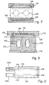
- FIG. 7 illustrates two-sided pressure compensation according to yet another embodiment of the present invention.
- an upper pressure transmitter is provided in the form of a pressure cell 100 with a diaphragm 102 .
- a lower pressure transmitter 104 which is adapted to influence an expansion forming tool 106 from below, comprises a rubber pad.
- the rubber pad 104 is provided with a seal 108 along its circumference to prevent extrusion.
- the rubber pad 104 is a passive element, whereas the diaphragm 102 is an active element.
- the diaphragm 102 transmits the liquid pressure behind it to the upper side of the tool 106 .
- the tool 106 will in its turn exert pressure on the underlying pad 104 , whose properties are similar to those of a liquid.
- the pressure distribution in the rubber pad 104 will be essentially hydrostatic and the rubber pad 104 will equalize any pressure differences on the under side of the tool 106 .
- FIGS. 4 , 5 and 7 show two-sided pressure compensation that is applied to the horizontal surfaces of the expansion forming tool, it is conceivable, within the scope of the invention, to apply instead two-sided pressure compensation to the vertical sides of the expansion forming tool.
- FIG. 8 illustrates one-sided pressure compensation according to one embodiment of the present invention.
- an upper press body part 110 and a lower press body part 112 are shown.
- the upper press body part 110 forms, together with a metal plate 114 , a pressure cell 116 .
- the pressure cell 116 is thus defined by a horizontal metal plate 114 or metal lamella, a horizontal portion 118 and a circumferential, vertical portion 120 of the upper press body part 110 .
- the transition between said horizontal portion 118 and said vertical portion 120 has the form of an indentation, among other things to reduces the stress in the material.
- the lower press body part 112 comprises a conventional press platen.
- a expansion forming tool 122 having two cavities 124 is arranged between the press platen and the metal plate.
- the metal plate 114 is flexible and provided with a circumferential seal 126 which provides a tight connection to the vertical portion 120 of the upper press body part 110 , so that no hydraulic liquid can flow past the metal plate 114 .
- Hydraulic liquid is supplied from a hydraulic system (not shown). Owing to the pressurising operation, the metal plates 114 will be moved towards the forming tool 122 and exert a compressive force thereon. Any deformations are compensated for by the flexible plate 114 , which can be easily tilted to transmit the liquid pressure behind, whereby pressure differences in the tool 122 are equalized.
- the liquid is evacuated from the pressure cell 116 by means of vacuum suction so that the metal plate 114 is pulled back from the tool 122 and a gap is formed which allows the tool to be removed from the press.
- the tool halves are separated outside the press, thus allowing access to the finished article.
- FIG. 9 is a top view of an expansion forming tool 130 to which two pressure intensifiers 132 a,b are connected.
- One pressure intensifier 132 b is illustrated schematically with its housing having been removed.
- the expansion forming tool 130 is quadrangular and rectangular.
- two elongate, pre-bent tubular blanks 134 can be disposed for expansion forming thereof.
- One example of the extension of the blanks 134 is shown by means of dotted lines.
- a plug 136 is provided at one end to prevent the pressure medium from flowing out, while the other end is connected to a pressure intensifier 132 a and 132 b , respectively.
- the pressure intensifier 132 a,b pumps a pressure medium into the hollow spaces of the blanks and increases the pressure so that the blanks are expanded against the inner cavity wall of the tool 130 .
- a dash and dot line indicates a pressure transmitter 138 , such as a diaphragm or a metal plate, which is adapted to be applied to the forming tool 130 for the purpose of pressure compensation.
- the pressure transmitter 138 has essentially the form of a rectangle, without any real corners, and covers a large part of the forming tool 130 .
- two pressure intensifiers of a type corresponding to the pressure intensifiers 132 a and 132 b can be arranged at the same location. In this case, it will be possible to pressurise each tubular blank from both ends at the same time.
- FIG. 10 illustrates one example of handling expansion forming tools.
- the press 150 is of the same type as that shown in FIG. 4 .
- an upper pressure cell 152 a and a lower pressure cell 152 b with diaphragms are included, an expansion forming tool being insertable between them.
- at least two tools 156 a,b are used in a press.
- the other tool 156 b is located outside the press.
- a manipulator not shown
- the upper tool half of the other tool 156 b is lifted to allow a finished article to be removed from the tool 156 b and a new blank is arranged in its place.
- the manipulator then lowers the upper tool half and keeps the halves in a compressed state.
- the tool 156 situated in the press 150 is removed from one end thereof, the other, prepared tool 156 is simultaneously introduced in the press 150 from the other end.
- the expansion of the diaphragms is controlled by means of a hydraulic system 158 , which during the tool change empties the pressure cells 152 a,b by means of vacuum suction in such manner that a gap is formed between each diaphragm and the tool to be taken out, which also allows easy insertion of the new tool.
- the lower pressure cell 152 b is situated below the ground level, for example embedded in the floor.
- other alternatives are also conceivable.
- the present invention can be used to avoid such deflections that are caused by conventional closing means.
- the invention further offers the opportunity to reduce the dimensions of the tool itself, since the internal forming forces are counteracted by an external liquid pressure transmitted through a pressure transmitter of the kind described above.
- the invention thus allows a high degree of accuracy to be obtained in the articles produced by means of expansion forming.
Abstract
Description
Claims (36)
Priority Applications (1)
| Application Number | Priority Date | Filing Date | Title |
|---|---|---|---|
| US10/513,707 US7509827B2 (en) | 2002-05-08 | 2003-04-04 | Device and method for expansion forming |
Applications Claiming Priority (7)
| Application Number | Priority Date | Filing Date | Title |
|---|---|---|---|
| SE0201415A SE0201415D0 (en) | 2002-05-08 | 2002-05-08 | Device and method for expansion molding |
| SE0201415-7 | 2002-05-08 | ||
| US38042402P | 2002-05-13 | 2002-05-13 | |
| SE0201470-2 | 2002-05-15 | ||
| SE0201470A SE522158C2 (en) | 2002-05-08 | 2002-05-15 | Expansion forming device for forming, e.g. tubular side beams, has two pressure transmitters for exerting and equalizing pressure differences between portions of outer faces of a tool during expansion forming |
| PCT/SE2003/000543 WO2003095122A1 (en) | 2002-05-08 | 2003-04-04 | Device and method for expansion forming |
| US10/513,707 US7509827B2 (en) | 2002-05-08 | 2003-04-04 | Device and method for expansion forming |
Publications (2)
| Publication Number | Publication Date |
|---|---|
| US20060075796A1 US20060075796A1 (en) | 2006-04-13 |
| US7509827B2 true US7509827B2 (en) | 2009-03-31 |
Family
ID=29424280
Family Applications (1)
| Application Number | Title | Priority Date | Filing Date |
|---|---|---|---|
| US10/513,707 Expired - Fee Related US7509827B2 (en) | 2002-05-08 | 2003-04-04 | Device and method for expansion forming |
Country Status (4)
| Country | Link |
|---|---|
| US (1) | US7509827B2 (en) |
| EP (1) | EP1539394B1 (en) |
| AU (1) | AU2003222539A1 (en) |
| WO (1) | WO2003095122A1 (en) |
Cited By (2)
| Publication number | Priority date | Publication date | Assignee | Title |
|---|---|---|---|---|
| US20120119423A1 (en) * | 2009-05-15 | 2012-05-17 | Silexcomp Oy | Method and mould arrangement for manufacturing articles with the help of a mould |
| US20170095854A1 (en) * | 2014-06-19 | 2017-04-06 | Sumitomo Heavy Industries, Ltd. | Molding apparatus, method for replacing components of modling apparatus, and replacement unit for molding apparatus |
Families Citing this family (5)
| Publication number | Priority date | Publication date | Assignee | Title |
|---|---|---|---|---|
| DE102006003981B4 (en) * | 2006-01-27 | 2010-12-09 | Theodor Gräbener GmbH & Co. KG | Hydroforming press for the production of molded parts by hydroforming |
| ES2374020T3 (en) * | 2009-02-20 | 2012-02-13 | Theodor Grabener Gmbh & Co. Kg | HYDROFORMATION TOOL. |
| WO2014167693A1 (en) | 2013-04-11 | 2014-10-16 | ルネサスエレクトロニクス株式会社 | Production method for semiconductor device |
| CN106001291B (en) * | 2016-06-08 | 2018-02-23 | 广东鸿业机械有限公司 | The pattern that rises mould structure and crimping unit |
| DE102019005916A1 (en) * | 2019-08-22 | 2021-02-25 | Siempelkamp Maschinen- Und Anlagenbau Gmbh | Method for pre-tensioning the membrane of a membrane press and press for performing this method |
Citations (13)
| Publication number | Priority date | Publication date | Assignee | Title |
|---|---|---|---|---|
| US3120205A (en) | 1956-02-07 | 1964-02-04 | Gen Tire & Rubber Co | Forming pad for hydraulic press |
| US4079613A (en) * | 1975-06-24 | 1978-03-21 | Allmanna Svenska Elektriska Aktiebolaget | Press with expansible pressure cell and forming pad |
| US4317348A (en) * | 1979-08-28 | 1982-03-02 | Mannesmann Aktiengesellschaft | Making contoured hollows |
| SE450227B (en) | 1985-04-18 | 1987-06-15 | Asea Ab | PRESSURE OF CELL TYPE |
| US4966029A (en) * | 1988-04-25 | 1990-10-30 | Haemmerle Ag | Method of bending a workpiece to a predetermined bending angle |
| EP0873802A1 (en) | 1997-04-25 | 1998-10-28 | Sumitomo Metal Industries, Ltd. | Method and apparatus for hydroforming metallic tube |
| US5927120A (en) | 1997-07-30 | 1999-07-27 | Dana Corporation | Apparatus for performing a hydroforming operation |
| WO2000000309A1 (en) | 1998-06-26 | 2000-01-06 | Flow Holdings Gmbh (Sagl) Limited Liability Company | Device and method for expansion forming |
| US6041633A (en) * | 1997-02-12 | 2000-03-28 | Anton Bauer Werkzeug- Und Maschinenbau Gmbh & Co. Kg | Forming apparatus |
| WO2002043890A1 (en) | 2000-11-28 | 2002-06-06 | Flow Holdings Sagl | Hydraulic press with a pressure cell and a method and use for it, whose press body consists of prestressed lamellas |
| EP1216769A2 (en) | 2000-12-23 | 2002-06-26 | DaimlerChrysler AG | Method and apparatus for making a closed hollow section |
| US6530252B1 (en) * | 1999-06-21 | 2003-03-11 | Aida Engineering Co., Ltd. | Hydroforming method and hydroforming device |
| US7047780B2 (en) * | 2001-06-29 | 2006-05-23 | Dana Corporation | Apparatus for performing a hydroforming operation |
-
2003
- 2003-04-04 US US10/513,707 patent/US7509827B2/en not_active Expired - Fee Related
- 2003-04-04 WO PCT/SE2003/000543 patent/WO2003095122A1/en not_active Application Discontinuation
- 2003-04-04 EP EP03717840A patent/EP1539394B1/en not_active Expired - Lifetime
- 2003-04-04 AU AU2003222539A patent/AU2003222539A1/en not_active Abandoned
Patent Citations (16)
| Publication number | Priority date | Publication date | Assignee | Title |
|---|---|---|---|---|
| US3120205A (en) | 1956-02-07 | 1964-02-04 | Gen Tire & Rubber Co | Forming pad for hydraulic press |
| US4079613A (en) * | 1975-06-24 | 1978-03-21 | Allmanna Svenska Elektriska Aktiebolaget | Press with expansible pressure cell and forming pad |
| US4317348A (en) * | 1979-08-28 | 1982-03-02 | Mannesmann Aktiengesellschaft | Making contoured hollows |
| SE450227B (en) | 1985-04-18 | 1987-06-15 | Asea Ab | PRESSURE OF CELL TYPE |
| US4676086A (en) * | 1985-04-18 | 1987-06-30 | Asea Aktiebolag | Press of pressure cell type |
| US4966029A (en) * | 1988-04-25 | 1990-10-30 | Haemmerle Ag | Method of bending a workpiece to a predetermined bending angle |
| US6041633A (en) * | 1997-02-12 | 2000-03-28 | Anton Bauer Werkzeug- Und Maschinenbau Gmbh & Co. Kg | Forming apparatus |
| EP0873802A1 (en) | 1997-04-25 | 1998-10-28 | Sumitomo Metal Industries, Ltd. | Method and apparatus for hydroforming metallic tube |
| US5927120A (en) | 1997-07-30 | 1999-07-27 | Dana Corporation | Apparatus for performing a hydroforming operation |
| WO2000000309A1 (en) | 1998-06-26 | 2000-01-06 | Flow Holdings Gmbh (Sagl) Limited Liability Company | Device and method for expansion forming |
| US6530252B1 (en) * | 1999-06-21 | 2003-03-11 | Aida Engineering Co., Ltd. | Hydroforming method and hydroforming device |
| WO2002043890A1 (en) | 2000-11-28 | 2002-06-06 | Flow Holdings Sagl | Hydraulic press with a pressure cell and a method and use for it, whose press body consists of prestressed lamellas |
| EP1216769A2 (en) | 2000-12-23 | 2002-06-26 | DaimlerChrysler AG | Method and apparatus for making a closed hollow section |
| US20020088263A1 (en) | 2000-12-23 | 2002-07-11 | Kai-Uwe Dudziak | Method for producing a circumferentially closed hollow profile and device for performing the method |
| US6634198B2 (en) | 2000-12-23 | 2003-10-21 | Daimlerchrysler Ag | Method for producing a circumferentially closed hollow profile and device for performing the method |
| US7047780B2 (en) * | 2001-06-29 | 2006-05-23 | Dana Corporation | Apparatus for performing a hydroforming operation |
Cited By (5)
| Publication number | Priority date | Publication date | Assignee | Title |
|---|---|---|---|---|
| US20120119423A1 (en) * | 2009-05-15 | 2012-05-17 | Silexcomp Oy | Method and mould arrangement for manufacturing articles with the help of a mould |
| US20170095854A1 (en) * | 2014-06-19 | 2017-04-06 | Sumitomo Heavy Industries, Ltd. | Molding apparatus, method for replacing components of modling apparatus, and replacement unit for molding apparatus |
| CN106660103A (en) * | 2014-06-19 | 2017-05-10 | 住友重机械工业株式会社 | Molding device, method for replacing molding device components, and replacement unit for molding device |
| US9855593B2 (en) * | 2014-06-19 | 2018-01-02 | Sumitomo Heavy Industries, Ltd. | Molding apparatus, method for replacing components of molding apparatus, and replacement unit for molding apparatus |
| CN106660103B (en) * | 2014-06-19 | 2018-04-13 | 住友重机械工业株式会社 | Molding machine, molding machine component replacing options and molding machine with replace unit |
Also Published As
| Publication number | Publication date |
|---|---|
| WO2003095122A1 (en) | 2003-11-20 |
| EP1539394A1 (en) | 2005-06-15 |
| US20060075796A1 (en) | 2006-04-13 |
| EP1539394B1 (en) | 2013-03-06 |
| AU2003222539A1 (en) | 2003-11-11 |
Similar Documents
| Publication | Publication Date | Title |
|---|---|---|
| RU2401714C2 (en) | Bottom-drive press | |
| US4676086A (en) | Press of pressure cell type | |
| CN101421521A (en) | Procedure for the loading of a working cylinder, control module for it, working cylinder and utilization of the same | |
| GB1570120A (en) | Press for shapping sheet metal | |
| US7509827B2 (en) | Device and method for expansion forming | |
| GB1599207A (en) | Cold forming process and apparatus | |
| US8387524B2 (en) | Apparatus and method for compensating for stress deformation in a press | |
| US7806031B1 (en) | Device for finely cutting workpieces from a material | |
| WO2005065927A1 (en) | Mechanical press device | |
| KR100593227B1 (en) | Hydromechanical closing device, in particular for lateral extrusion | |
| US7320211B2 (en) | Method of exchanging a diaphragm device | |
| KR20070078737A (en) | Hydroforming press for manufacturing formed parts by internal high pressure deformation | |
| KR0163378B1 (en) | Press having gas cylinder or plastically deformable members for even distribution of blank-holding force on pressure member through cashing pin | |
| JP3057259U (en) | Flexible dies | |
| JPS6161918B2 (en) | ||
| US7150171B2 (en) | Pressure cell press comprising a tray, and a method for manufacturing said tray | |
| US3450035A (en) | Hydraulic press | |
| EP1302254B1 (en) | Equalizing fluid-operated apparatus and method of assembling the apparatus | |
| KR100883314B1 (en) | Thomson press | |
| JP4430920B2 (en) | Ultra high pressure press | |
| CN2931064Y (en) | Vertical compression type mould-clipping mechanism for hot press | |
| CN117399470A (en) | Deflection self-adaptive compensation device and bending machine comprising same | |
| JP2002066301A (en) | Solid state very high pressure generator | |
| KR880000952B1 (en) | Press apparatus having working surface constituted by fiaating plate | |
| US20040065138A1 (en) | Hydraulic press with pressure cell with a tray whic consists of prestressed lamellas |
Legal Events
| Date | Code | Title | Description |
|---|---|---|---|
| AS | Assignment |
Owner name: BANK OF AMERICA, N.A.,WASHINGTON Free format text: SECURITY AGREEMENT;ASSIGNOR:FLOW INTERNATIONAL CORPORATION;REEL/FRAME:016283/0522 Effective date: 20050708 Owner name: BANK OF AMERICA, N.A., WASHINGTON Free format text: SECURITY AGREEMENT;ASSIGNOR:FLOW INTERNATIONAL CORPORATION;REEL/FRAME:016283/0522 Effective date: 20050708 |
|
| AS | Assignment |
Owner name: FLOW HOLDINGS GMBH (SAGL) LIMITED LIABILITY COMPAN Free format text: ASSIGNMENT OF ASSIGNORS INTEREST;ASSIGNOR:HELLGREN, KEIJO;REEL/FRAME:017376/0664 Effective date: 20050601 |
|
| AS | Assignment |
Owner name: FLOW INTERNATIONAL CORPORATION,WASHINGTON Free format text: RELEASE BY SECURED PARTY;ASSIGNOR:BANK OF AMERICA, N.A.;REEL/FRAME:016745/0894 Effective date: 20051031 Owner name: FLOW INTERNATIONAL CORPORATION, WASHINGTON Free format text: RELEASE BY SECURED PARTY;ASSIGNOR:BANK OF AMERICA, N.A.;REEL/FRAME:016745/0894 Effective date: 20051031 |
|
| AS | Assignment |
Owner name: AVURE TECHNOLOGIES AB, SWEDEN Free format text: ASSIGNMENT OF ASSIGNORS INTEREST;ASSIGNOR:FLOW HOLDINGS SAGL;REEL/FRAME:016769/0128 Effective date: 20051031 Owner name: AVURE TECHNOLOGIES AB,SWEDEN Free format text: ASSIGNMENT OF ASSIGNORS INTEREST;ASSIGNOR:FLOW HOLDINGS SAGL;REEL/FRAME:016769/0128 Effective date: 20051031 |
|
| STCF | Information on status: patent grant |
Free format text: PATENTED CASE |
|
| FEPP | Fee payment procedure |
Free format text: PAYOR NUMBER ASSIGNED (ORIGINAL EVENT CODE: ASPN); ENTITY STATUS OF PATENT OWNER: LARGE ENTITY |
|
| FPAY | Fee payment |
Year of fee payment: 4 |
|
| AS | Assignment |
Owner name: QUINTUS TECHNOLOGIES AB, SWEDEN Free format text: CHANGE OF NAME;ASSIGNOR:AVURE TECHNOLOGIES AB;REEL/FRAME:039723/0723 Effective date: 20160112 |
|
| FPAY | Fee payment |
Year of fee payment: 8 |
|
| FEPP | Fee payment procedure |
Free format text: MAINTENANCE FEE REMINDER MAILED (ORIGINAL EVENT CODE: REM.); ENTITY STATUS OF PATENT OWNER: LARGE ENTITY |
|
| LAPS | Lapse for failure to pay maintenance fees |
Free format text: PATENT EXPIRED FOR FAILURE TO PAY MAINTENANCE FEES (ORIGINAL EVENT CODE: EXP.); ENTITY STATUS OF PATENT OWNER: LARGE ENTITY |
|
| STCH | Information on status: patent discontinuation |
Free format text: PATENT EXPIRED DUE TO NONPAYMENT OF MAINTENANCE FEES UNDER 37 CFR 1.362 |
|
| FP | Lapsed due to failure to pay maintenance fee |
Effective date: 20210331 |