US7523783B2 - Internal shock absorber plunger - Google Patents
Internal shock absorber plunger Download PDFInfo
- Publication number
- US7523783B2 US7523783B2 US11/009,997 US999704A US7523783B2 US 7523783 B2 US7523783 B2 US 7523783B2 US 999704 A US999704 A US 999704A US 7523783 B2 US7523783 B2 US 7523783B2
- Authority
- US
- United States
- Prior art keywords
- plunger
- shock absorber
- internal
- shock absorbing
- well
- Prior art date
- Legal status (The legal status is an assumption and is not a legal conclusion. Google has not performed a legal analysis and makes no representation as to the accuracy of the status listed.)
- Active, expires
Links
- 230000035939 shock Effects 0.000 title claims abstract description 138
- 239000006096 absorbing agent Substances 0.000 title claims abstract description 66
- 238000013461 design Methods 0.000 claims description 22
- 229920001971 elastomer Polymers 0.000 claims description 15
- 239000000806 elastomer Substances 0.000 claims description 15
- 239000012530 fluid Substances 0.000 claims description 8
- 230000000630 rising effect Effects 0.000 claims description 5
- 230000007246 mechanism Effects 0.000 abstract description 5
- 230000001737 promoting effect Effects 0.000 abstract 1
- 239000007788 liquid Substances 0.000 description 21
- 230000009977 dual effect Effects 0.000 description 13
- 238000004519 manufacturing process Methods 0.000 description 6
- 230000013011 mating Effects 0.000 description 6
- 230000000712 assembly Effects 0.000 description 5
- 238000000429 assembly Methods 0.000 description 5
- 230000015572 biosynthetic process Effects 0.000 description 4
- 210000002445 nipple Anatomy 0.000 description 4
- 239000007787 solid Substances 0.000 description 4
- 238000010521 absorption reaction Methods 0.000 description 3
- 238000009434 installation Methods 0.000 description 3
- 239000000463 material Substances 0.000 description 3
- 239000012188 paraffin wax Substances 0.000 description 3
- 239000003208 petroleum Substances 0.000 description 3
- 229920002449 FKM Polymers 0.000 description 2
- 238000007792 addition Methods 0.000 description 2
- 239000000446 fuel Substances 0.000 description 2
- 239000003129 oil well Substances 0.000 description 2
- 230000009467 reduction Effects 0.000 description 2
- 150000003839 salts Chemical class 0.000 description 2
- 239000000126 substance Substances 0.000 description 2
- 239000004215 Carbon black (E152) Substances 0.000 description 1
- 208000032953 Device battery issue Diseases 0.000 description 1
- 239000004677 Nylon Substances 0.000 description 1
- 241000270295 Serpentes Species 0.000 description 1
- 229910000831 Steel Inorganic materials 0.000 description 1
- 229920006362 Teflon® Polymers 0.000 description 1
- 230000009471 action Effects 0.000 description 1
- 239000003245 coal Substances 0.000 description 1
- 238000010276 construction Methods 0.000 description 1
- 230000001351 cycling effect Effects 0.000 description 1
- 238000012217 deletion Methods 0.000 description 1
- 230000037430 deletion Effects 0.000 description 1
- 230000000694 effects Effects 0.000 description 1
- 230000008030 elimination Effects 0.000 description 1
- 238000003379 elimination reaction Methods 0.000 description 1
- 229930195733 hydrocarbon Natural products 0.000 description 1
- 150000002430 hydrocarbons Chemical class 0.000 description 1
- 238000010348 incorporation Methods 0.000 description 1
- 238000012423 maintenance Methods 0.000 description 1
- 230000014759 maintenance of location Effects 0.000 description 1
- 238000000034 method Methods 0.000 description 1
- 238000012986 modification Methods 0.000 description 1
- 230000004048 modification Effects 0.000 description 1
- 229920001778 nylon Polymers 0.000 description 1
- 239000004576 sand Substances 0.000 description 1
- 229910001220 stainless steel Inorganic materials 0.000 description 1
- 239000010935 stainless steel Substances 0.000 description 1
- 239000010959 steel Substances 0.000 description 1
Images


Classifications
-
- E—FIXED CONSTRUCTIONS
- E21—EARTH DRILLING; MINING
- E21B—EARTH DRILLING, e.g. DEEP DRILLING; OBTAINING OIL, GAS, WATER, SOLUBLE OR MELTABLE MATERIALS OR A SLURRY OF MINERALS FROM WELLS
- E21B17/00—Drilling rods or pipes; Flexible drill strings; Kellies; Drill collars; Sucker rods; Cables; Casings; Tubings
- E21B17/02—Couplings; joints
- E21B17/04—Couplings; joints between rod or the like and bit or between rod and rod or the like
- E21B17/07—Telescoping joints for varying drill string lengths; Shock absorbers
-
- E—FIXED CONSTRUCTIONS
- E21—EARTH DRILLING; MINING
- E21B—EARTH DRILLING, e.g. DEEP DRILLING; OBTAINING OIL, GAS, WATER, SOLUBLE OR MELTABLE MATERIALS OR A SLURRY OF MINERALS FROM WELLS
- E21B17/00—Drilling rods or pipes; Flexible drill strings; Kellies; Drill collars; Sucker rods; Cables; Casings; Tubings
- E21B17/10—Wear protectors; Centralising devices, e.g. stabilisers
- E21B17/1071—Wear protectors; Centralising devices, e.g. stabilisers specially adapted for pump rods, e.g. sucker rods
-
- E—FIXED CONSTRUCTIONS
- E21—EARTH DRILLING; MINING
- E21B—EARTH DRILLING, e.g. DEEP DRILLING; OBTAINING OIL, GAS, WATER, SOLUBLE OR MELTABLE MATERIALS OR A SLURRY OF MINERALS FROM WELLS
- E21B43/00—Methods or apparatus for obtaining oil, gas, water, soluble or meltable materials or a slurry of minerals from wells
- E21B43/12—Methods or apparatus for controlling the flow of the obtained fluid to or in wells
- E21B43/121—Lifting well fluids
-
- F—MECHANICAL ENGINEERING; LIGHTING; HEATING; WEAPONS; BLASTING
- F04—POSITIVE - DISPLACEMENT MACHINES FOR LIQUIDS; PUMPS FOR LIQUIDS OR ELASTIC FLUIDS
- F04B—POSITIVE-DISPLACEMENT MACHINES FOR LIQUIDS; PUMPS
- F04B47/00—Pumps or pumping installations specially adapted for raising fluids from great depths, e.g. well pumps
- F04B47/12—Pumps or pumping installations specially adapted for raising fluids from great depths, e.g. well pumps having free plunger lifting the fluid to the surface
-
- F—MECHANICAL ENGINEERING; LIGHTING; HEATING; WEAPONS; BLASTING
- F04—POSITIVE - DISPLACEMENT MACHINES FOR LIQUIDS; PUMPS FOR LIQUIDS OR ELASTIC FLUIDS
- F04B—POSITIVE-DISPLACEMENT MACHINES FOR LIQUIDS; PUMPS
- F04B53/00—Component parts, details or accessories not provided for in, or of interest apart from, groups F04B1/00 - F04B23/00 or F04B39/00 - F04B47/00
- F04B53/14—Pistons, piston-rods or piston-rod connections
- F04B53/144—Adaptation of piston-rods
- F04B53/145—Rod shock absorber
Definitions
- the present invention relates to a plunger lift apparatus for the lifting of formation liquids in a hydrocarbon well. More specifically the plunger consists of an internal shock absorber apparatus that operates to absorb shock during plunger fall and high velocity plunger rise.
- a plunger lift is an apparatus that is used to increase the productivity of oil and gas wells. Nearly all wells produce liquids. In the early stages of a well's life, liquid loading is usually not a problem. When rates are high, the well liquids are carried out of the well tubing by the high velocity gas. As a well declines, a critical velocity is reached below which the heavier liquids do not make it to the surface and start to fall back to the bottom exerting back pressure on the formation, thus loading up the well.
- a plunger system is a method of unloading gas in high ratio oil wells without interrupting production. In operation, the plunger travels to the bottom of the well where the loading fluid is picked up by the plunger and is brought to the surface removing all liquids in the tubing.
- the plunger also keeps the tubing free of paraffin, salt or scale build-up.
- a plunger lift system works by cycling a well open and closed. During the open time a plunger interfaces between a liquid slug and gas. The gas below the plunger will push the plunger and liquid to the surface. This removal of the liquid from the tubing bore allows an additional volume of gas to flow from a producing well.
- a plunger lift requires sufficient gas presence within the well to be functional in driving the system. Oil wells making no gas are thus not plunger lift candidates.
- Lubricator assembly 10 is one of the most important components of plunger system 100 .
- Lubricator assembly 10 includes cap 1 , integral top bumper spring 2 , striking pad 3 , and extracting rod 4 . Extracting rod 4 may or may not be employed depending on the plunger type.
- Contained within lubricator assembly 10 is plunger auto catching device 5 and plunger sensing device 6 .
- Sensing device 6 sends a signal to surface controller 15 upon plunger 200 arrival at the well top.
- Plunger 200 can represent the plunger of the present invention or other prior art plungers. Sensing the plunger is used as a programming input to achieve the desired well production, flow times and wellhead operating pressures.
- Master valve 7 should be sized correctly for the tubing 9 and plunger 200 . An incorrectly sized master valve 7 will not allow plunger 200 to pass through. Master valve 7 should incorporate a full bore opening equal to the tubing 9 size. An oversized valve will allow gas to bypass the plunger causing it to stall in the valve. If the plunger is to be used in a well with relatively high formation pressures, care must be taken to balance tubing 9 size with the casing 8 size.
- the bottom of a well is typically equipped with a seating nipple/tubing stop 12 .
- Spring standing valve/bottom hole bumper assembly 11 is located near the tubing bottom. The bumper spring is located above the standing valve and can be manufactured as an integral part of the standing valve or as a separate component of the plunger system. The bumper spring typically protects the tubing from plunger impact in the absence of fluid. Fluid accumulating on top of plunger 200 may be carried to the well top by plunger 200 .
- Surface control equipment usually consists of motor valve(s) 14 , sensors 6 , pressure recorders 16 , etc., and an electronic controller 15 which opens and closes the well at the surface.
- Well flow ‘F’ proceeds downstream when surface controller 15 opens well head flow valves.
- Controllers operate on time, or pressure, to open or close the surface valves based on operator-determined requirements for production.
- Modern electronic controllers incorporate features that are user friendly, easy to program, addressing the shortcomings of mechanical controllers and early electronic controllers. Additional features include: battery life extension through solar panel recharging, computer memory program retention in the event of battery failure and built-in lightning protection. For complex operating conditions, controllers can be purchased that have multiple valve capability to fully automate the production process.
- FIGS. 2 , 2 A, 2 B, 2 C are side views of the upper sections of various plunger embodiments.
- Various existing sidewall geometries can be used in conjunction with the present apparatus.
- an upper section of the plunger embodiment comprises a top collar shown with a standard American Petroleum Institute (API) internal fishing neck A. If retrieval is required, a spring loaded ball within a retriever and protruding outside its surface would thus fall within the API internal fishing neck at the top of the plunger, wherein the inside diameter of the orifice would increase to allow the ball to spring outward. This condition would allow retrieving of the plunger if, and when, necessary.
- each upper section comprises an upper end sleeve 41 and an upper threaded male section 42 used to attach various bottom ends, which will be described below.
- Plungers use the volume of gas stored in the casing and the formation during the shut-in time to push the liquid load and plunger to the surface when the motor valve opens the well to the sales line or to the atmosphere.
- the pressure and gas volume in the tubing/casing annulus is usually considered as the source of energy for bringing the liquid load and plunger to the surface.
- a plunger will fall towards the well bottom at a relatively high velocity.
- the impact is absorbed in part by the plunger, the spring standing valve/bottom hole bumper assembly 11 , the seating nipple/tubing stop 12 and the well bottom ( FIG. 1 ).
- a higher velocity could lead to greater impact force and can result in damage to the plunger, and/or the spring standing valve/bottom hole bumper assembly.
- Bumper springs could collapse over time due to repeated stress caused by impact force. Also, plunger damage can occur resulting in more frequent plunger replacement.
- a plunger could also rise at a high velocity from the well bottom to the well top. This can occur when liquid levels are low or when an operator allows the plunger to lift prior to proper liquid loading. A high velocity rise could cause damage to the well top apparatus and to the plunger itself. Damage to well apparatus and plunger lift equipment typically increases well maintenance costs.
- FIG. 3 shows prior art pad plunger mandrel 60 geometry (see FIG. 2 ) with a fishing neck top section A, and the addition of an external bottom spring 32 attached via weld 31 .
- the prior art solution with such an external spring, acting as a shock absorber, tends to add reliability problems to both the plunger and well bottom assembly. Failures of the weld and/or spring can occur. In addition, a failed plunger can place more wear and tear on the well bottom seating nipple/tubing stop and spring standing valve/bottom hole bumper assembly.
- the present apparatus provides a plunger lift system with a more reliable shock absorber.
- wells could be constructed with or without bumper spring assemblies, which typically operate to slow a plunger's travel.
- bumper spring assemblies In well applications which do not utilize bumper spring assemblies, fewer obstructions or restrictions are encountered by a plunger at the well bottom. In these cases, plunger travel can be more optimal and plunger damage can be reduced or minimized.
- plunger structure has less effect on the physical restrictions of a well bottom and any equipment housed therein.
- the present apparatus can be used if a reduction of well top damage (as in the case of high velocity plunger rise) and a reduction of well bottom damage (as in the case of high velocity plunger fall), is desired.
- the components of the present apparatus are easy to manufacture and easy to assemble.
- the main aspect of the present invention is to provide an internal shock absorber plunger apparatus in a high liquid well when plunger falling velocity produces a large impact force at the well bottom.
- Another aspect of the present invention is to provide an internal shock absorber plunger apparatus that will protect the well top apparatus and the plunger when a high velocity plunger rise occurs.
- Another aspect of the present invention is to provide a spring within the plunger to function as the shock absorbing body.
- Another aspect of the present invention is to allow for fewer restrictions on a well bottom.
- Another aspect of the present invention is to provide a shock absorber plunger that will increase reliability levels.
- Another aspect of the present invention is to provide a shock absorber plunger that will efficiently force fall inside the tubing to the well-hole bottom with increased speed without impeding plunger or well bottom damage.
- Another aspect of the present invention is to provide a shock absorber plunger that can be used with any existing plunger sidewall geometry.
- Another aspect of the present invention is to allow for a shock absorber plunger that can be easily manufactured.
- the present invention comprises a plunger apparatus having an internal shock absorber to increase plunger life as well as to increase life of components found at a well bottom and a well top.
- the internal shock absorber can comprise an elastomer spring, die coil spring or wave spring, other shock absorbing mechanisms can be used.
- An actuator rod within the plunger hits the bottom of the well and compresses the internal spring, which absorbs all or part of the impact shock.
- the present invention comprises a plunger lift apparatus consisting of a top section, which is typically a standard American Petroleum Institute (API) fishing neck, or other designs; a solid core mid section allowing for various aforementioned sidewall geometries; and a lower internal shock absorber section.
- the lower internal shock absorber section can be designed in various ways but will basically consist of an actuator rod, a captive actuator and an internal spring.
- the internal spring can be a wave spring, a die coil spring, or an elastomer-type spring (i.e. Viton®, etc.), which offers excellent resistance to aggressive fuels and chemicals.
- One of the additional embodiments of the present invention will incorporate dual shock absorber sections, that is, a shock absorbing element at each end section, one at the top and one at the bottom of the plunger. Yet another additional embodiment will incorporate a mid-section shock absorber element.
- the internal shock absorber plunger of the present invention allows for improved reliability in wells that have high fluid velocities with respect to falling plungers. It allows for fewer restrictions at the well bottom, high reliability, ease of manufacture, and incorporation of the design into existing plunger geometries.
- FIG. 1 (prior art) is an overview depiction of a typical plunger lift system installation
- FIGS. 2 , 2 A, 2 B, 2 C are side view depictions of the upper section of a well plunger, each having a different sidewall geometry.
- FIG. 3 (prior art) is a side view of pad plunger with an externally attached spring.
- FIG. 4 is a side cross-sectional view of a lower section of an internal shock absorber embodiment using a standard die coil spring.
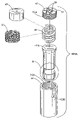
- FIG. 5 is an isometric exploded view of the lower section of the internal shock absorber plunger embodiment shown in FIG. 4 .
- FIG. 6 is a side cross-sectional view of a lower section of the internal shock absorber plunger of an alternate embodiment using a standard die coil spring.
- FIG. 7 is an isometric exploded view of the lower section of the internal shock absorber plunger embodiment shown in FIG. 6 .
- FIGS. 8 , 8 A, 8 B, 8 C are side view depictions of the internal shock absorber plunger utilizing various sidewall geometries.
- FIGS. 9 , 9 A, 9 B, 9 C are side view depictions of the central section of a dual internal shock absorber plunger embodiment shown in conjunction with existing prior art sidewall geometries.
- FIG. 10 is a side cross-sectional view of an upper assembly for an embodiment comprising a dual internal shock absorber.
- FIG. 11 is an isometric exploded view of the upper shock absorbing assembly of FIG. 10 for the dual internal shock absorber.
- FIG. 12 is a side cross-sectional view of an alternate embodiment of an upper shock absorbing assembly for a dual internal shock absorber plunger.
- FIG. 13 is an isometric exploded view of the upper shock absorbing assembly of FIG. 12 for the dual internal shock absorber plunger.
- FIG. 14 is side view, including a mid-section cross-sectional view, of an internal shock absorber plunger embodiment having a shock absorbing mid-section.
- FIG. 15 is an isometric exploded view of the casing assembly of a mid-section internal shock absorber plunger.
- the drawings depict an internal shock absorber plunger apparatus that can improve productivity levels in high liquid wells when plunger falling velocity produces a large impact force at the well bottom.
- the present apparatus can be used in well applications with or without a bumper spring.
- the rising velocity can be several times faster than a falling velocity due to well pressure conditions.
- high velocity lift can occur in low liquid wells, as well as in instances when an operator will cycle the plunger prior to liquid loading.
- the present invention can also protect the plunger and the apparatus at the well top in the case of a high velocity lift.
- FIG. 4 shows lower removable assembly 300 of the internal shock absorber plunger housing an internal shock absorber.
- Lower removable assembly 300 can be added to any aforementioned geometric upper section.
- lower removable assembly 300 comprises actuator rod (piston) 36 having external thread interface 52 A, captive nut (cap) 35 having external thread interface 54 A, shock absorbing elastomer spring 49 , seal nut 34 having internal thread interface 52 B, and case housing (cylinder wall) 33 having internal thread interface 54 B at its lower end, also having an inner lower ledge to contain the upper end of shock absorbing elastomer spring 49 .
- case housing 33 has internal cavity 57 for accepting an upper end sleeve 41 .
- shock absorbing elastomer spring 49 could be replaced with any suitable shock absorbing mechanism.
- a shock absorbing die coil spring 48 or a shock absorbing wave type spring 47 as shown in FIG. 7 can be used.
- Shock absorbing elastomer spring 49 can be Viton® or any other type elastomer. Material selections can be tuned to well conditions such as temperature, falling/rising distance, resistance to fuels or chemicals present in the fluid, etc. The present invention is not limited by the type of or by the design of the internal spring.
- Spanner holes could be easily added to parts such as seal nut 34 , captive nut 35 , and other parts as required, to aid in fastening.
- actuator rod 36 When the plunger falls to the well bottom, actuator rod 36 will hit the seating bumper spring assembly that is located near the tubing bottom. In well applications having no bumper spring, the plunger will hit a hard stop at the well bottom. Both the bumper spring assembly and the internal shock absorber plunger of the present invention will absorb a portion of the force generated by the impact. If a bumper spring does not exist, impact force will be absorbed by the internal shock absorber. Upon impact, actuator rod 36 will move in direction ‘R’ and into shock absorbing elastomer spring 49 which will absorb a portion (or all) of the impact force. The ability of the plunger to self-absorb shock at the well bottom will thus increase reliability levels.
- the present invention provides an internal plunger shock absorption as the plunger top hits a top striking pad or other well top apparatus.
- FIG. 5 is an isometric exploded view of lower removable assembly 300 of FIG. 4 . It shows the basic five parts of lower removable assembly 300 ; actuator rod 36 has anvil B design with anvil groove 64 at one end has external thread interface 52 A at its other end, captive nut 35 with external thread interface 54 A, seal nut 34 with inner thread interface 52 B, shock absorbing elastomer spring 49 , and case housing 33 . Access external hole 62 A is for tightening lower removable assembly 300 to the upper section onto upper threaded male section 42 . It should be noted that anvil B design could easily be replaced with other end type designs. Assembly to upper sections is completed via threaded female section 56 .
- FIG. 6 is an alternate embodiment of the present invention showing alternate lower removable assembly 400 of the internal shock absorber plunger containing the internal shock absorber.
- the internal shock absorber comprises a shock absorbing die coil spring 48 .
- Lower removable assembly 400 is an alternate design to lower removable assembly 300 shown in FIGS. 4 , 5 . Alternate lower removable assembly 400 can be added to any aforementioned geometric top section in the same manner as previously described herein.
- Alternate lower removable assembly 400 comprises actuator rod (piston) 44 , shock absorbing die coil spring 48 , case housing (cylinder wall) 46 with internal female housing threaded area 51 B, and lock nut 45 which has internal female threaded area 53 for accepting an upper threaded male section 42 , and external male threaded section 51 A for mating with housing 46 via internal female housing threaded area 51 B. Grip holes 39 in lock nut 45 are used to grasp and mechanically tighten lock nut 45 .
- Actuator rod 44 has an outer flange at its upper surface to hold it within case housing 46 , which has an inner flange surface on its bottom side to hold actuator rod 44 within.
- Shock absorbing die coil spring 48 can be replaced with a more suitable shock absorbing element. As shown in dotted line format, shock absorbing wave spring 47 or with shock absorbing elastomer-type spring 49 could be used. The present invention is not limited by the spring type or by the spring design.
- actuator rod 44 When the plunger falls to the well bottom, actuator rod 44 will hit the seating bumper spring assembly or hit a hard stop at the well bottom. Upon impact, actuator rod 44 will move in direction ‘R’ and into shock absorbing coil spring 48 which will absorb a portion (or all) of the impact force. Likewise, when a plunger rises to the well top with a high velocity, damage is avoided as the top of the plunger hits well top apparatus and the internal shock absorbing coil spring 48 will absorb a portion (or all) of the impact force.
- FIG. 7 is an isometric blow-up view of lower removable assembly 400 of FIG. 6 .
- Lower removable assembly 400 consists of actuator rod (piston) 44 , die coil spring 48 , case housing 46 , and lock nut (threaded cap) 45 with internal female threaded area 53 for accepting upper threaded male section 42 (see FIGS. 2 , 2 A, 2 B, 2 C), and outside male threaded area 51 A for mating with housing 46 which has internal female housing threaded area 51 B.
- Grip holes 39 are used to grasp and mechanically tighten lock nut 45 .
- shock absorbing die coil type spring 48 can also be replaced with shock absorbing wave spring 47 or with an elastomer-type spring 49 .
- Access external hole 62 B is for tightening lower removable assembly 400 to the upper section onto upper threaded male section 42 .
- this embodiment basically consists of four parts in lower removable assembly 400 ; actuator rod 44 , shock absorbing die coil spring 48 , case housing 46 with internal female housing threaded area 51 B, and lock nut 45 with inside female threaded area 53 for accepting upper threaded male section 42 (see FIGS. 2 , 2 A, 2 B, 2 C), and outside male threaded area 51 A for mating with inner female threaded area 51 B on case housing 46 .
- shock absorbing die coil type spring 48 can also be replaced with any suitable shock absorbing element such as a shock absorbing wave spring 47 or a shock absorbing elastomer-type spring 49 . Assembly to upper sections is also via a simple thread at threaded interfaces 51 , 53 .
- removable assemblies have been shown with upper female type receptacles and upper plunger sections have been shown with lower male type sections for joining each other, other designs could easily be employed to have removable assemblies with male upper sections and female upper plunger sections with female lower sections for mating.
- FIGS. 8 , 8 A, 8 B, 8 C are side views of the internal shock absorber plunger utilizing various sidewall geometries (including but not limited to mandrel geometries 22 , 61 , 71 , 81 ).
- lower removable assembly 300 is shown in conjunction with plunger mandrel 20 having solid ring 22 geometry (see FIG. 8B ) and plunger mandrel 80 having shifting ring 81 geometry (see FIG. 8C ).
- Lower removable assembly 400 is shown in conjunction with plunger mandrel 60 (see FIG. 8 ) and plunger mandrel 70 (see FIG. 8A ). It should be noted that the present invention is not limited to any specific sidewall geometry and that any sidewall geometry can be used.
- FIGS. 8 , 8 A, 8 B, 8 C a standard American Petroleum Institute (API) internal fishing neck top A is shown in FIGS. 8 , 8 A, 8 B, 8 C.
- API American Petroleum Institute
- FIGS. 9 , 9 A, 9 B, 9 C, 10 , 11 , 12 , 13 A dual internal shock absorber embodiment is shown in FIGS. 9 , 9 A, 9 B, 9 C, 10 , 11 , 12 , 13 .
- ‘Dual shock absorbing sections can provide for additional shock absorption.
- This embodiment can be constructed by adding a second shock absorbing upper assembly to a first shock absorbing assembly.
- the additional shock absorbing assembly can allow for improved internal shock absorption as needed based on well conditions.
- FIGS. 9 , 9 A, 9 B, 9 C are side view depictions of the section between sleeves 41 A, 41 B of a dual internal shock absorber plunger embodiment shown in conjunction with existing prior art sidewall geometries.
- this embodiment comprises end sleeves 41 A, 41 B and threaded male sections 42 A, 42 B for accepting more than one shock absorber assembly. All geometries depicted can be found in present industrial offerings. Similar geometries also exist and will have internal orifices.
- Each mandrel central section 600 , 700 , 200 , 800 is symmetrically designed to hold both an upper shock absorbing assembly 300 A or 400 A ( FIGS. 10 , 11 , 12 , 13 ) and a lower shock absorbing assembly 300 or 400 ( FIGS. 4 , 5 , 6 , 7 ).
- FIG. 10 shows upper shock absorbing assembly 300 A for the dual internal shock absorber housing an elastomeric spring 49 .
- Elastomeric spring 49 can be replaced with other type springs such as a wave spring or a die coil spring. All elements of FIG. 10 are as described in FIG. 4 with the exception that actuator rod 36 A comprises a fishing neck A design.
- Upper shock absorbing assembly 300 A mates with central section 600 , 700 , 200 , 800 (see FIGS. 9 , 9 A, 9 B, 9 C) via internal cavity 57 for accepting end sleeve 41 B and threaded male section 42 B is received by threaded female section 56 .
- Threaded female section 56 of a lower shock absorbing assembly 300 or 400 can receive threaded male section 42 A.
- Internal cavity 57 may accept end sleeve 41 A.
- upper assembly 300 A provides for a second shock absorbing assembly forming a dual internal shock absorbing plunger embodiment.
- FIG. 11 is an isometric exploded view of the upper shock absorbing assembly 300 A of FIG. 10 . All parts of removable assembly 300 A are as previously described in FIG. 5 above with the exception that actuator rod 36 A has fishing neck A design for retrieval purposes.
- FIG. 12 is a side cross-sectional view of an alternate embodiment 400 A of an upper assembly for a dual internal shock absorber plunger.
- Upper assembly 400 A is an alternate design to upper assembly 300 A shown in FIG. 10 . All elements of FIG. 12 are as described in FIG. 6 with the exception that actuator rod 44 A has fishing neck A design.
- the present embodiment houses a shock absorber element comprising a die coil spring 48 . As stated above, any suitable shock absorbing element could be used.
- Upper shock absorbing assembly 400 A mates with central section 600 , 700 , 200 , 800 via internal threads 53 for accepting threaded male section 42 B (see FIGS. 9 , 9 A, 9 B, 9 C). Upper assembly 400 A provides for a second shock absorbing assembly forming a dual internal shock absorbing plunger.
- FIG. 13 is an isometric exploded view of upper shock absorber assembly 400 A shown in FIG. 12 . All parts of removable assembly 400 A are as previously described in FIG. 7 above with the exception that actuator rod 44 A has fishing neck A design for retrieval purposes.
- FIG. 14 is a side view, including a mid-section cross-sectional view, for a mid-section internal shock absorber plunger 500 embodiment.
- a shock absorber such as elastomer spring 49 will absorb some or all of the impact energy.
- casing assembly 506 houses mid-section casing 66 having threaded interfaces at either ends, one internal elastomer spring 49 , two captive nuts 34 for attaching upper mandrel 502 and lower mandrel 504 , and two captive nuts 35 for containing both mandrel sections.
- Shock absorbing elastomer spring 49 could be replaced with any suitable shock absorbing mechanism.
- a shock absorbing die coil spring 48 or a shock absorbing wave type spring 47 (as shown in FIG. 7 ) can be used.
- upper mandrel section 502 comprises a fishing neck A design
- lower mandrel section 504 comprises an anvil B end design as previously shown in FIGS. 4 , 5 , 8 , 8 A, 8 B, 8 C.
- mandrel sections 502 , 504 are shown with shifting ring geometry. Shifting rings 81 , are individually separated by air gaps 82 . It should be noted that although a shifting ring geometry is shown, other previously described sidewall geometries could also be used.
- FIG. 15 is an isometric exploded view of casing assembly 506 . Assembly of this plunger embodiment can be described as follows:
- the present invention can optimize well efficiency and plunger reliability.
- An internal shock absorber allows the present apparatus to quickly travel to the well bottom, or to quickly travel to the well top, while reducing damage caused by a forcible impact of the plunger against various well components.
- the internal shock absorber plunger can increase plunger life (by reducing plunger damage) as well as the life of components found at a well top and well bottom.
- the internalized design can also result in a well application with fewer restrictions at the well bottom.
- wells could be operated without equipment such as a bumper spring assembly, if desired.
- the internal shock absorber can utilize any suitable shock absorbing element to absorb all or part of the impact shock. Examples of such could include elastomer springs, die coil springs, wave springs, etc.
Landscapes
- Engineering & Computer Science (AREA)
- Life Sciences & Earth Sciences (AREA)
- Geology (AREA)
- Mining & Mineral Resources (AREA)
- Mechanical Engineering (AREA)
- Physics & Mathematics (AREA)
- Environmental & Geological Engineering (AREA)
- Fluid Mechanics (AREA)
- General Life Sciences & Earth Sciences (AREA)
- Geochemistry & Mineralogy (AREA)
- General Engineering & Computer Science (AREA)
- Vibration Dampers (AREA)
Abstract
Description
-
- A.
Plunger mandrel 20 is shown withsolid ring 22 sidewall geometry.Solid sidewall rings 22 can be made of various materials such as steel, poly materials, Teflon®, stainless steel, etc.Inner cut grooves 30 allow sidewall debris to accumulate when a plunger is rising or falling. -
B. Plunger mandrel 80 is shown with shiftingring 81 sidewall geometry. Shiftingrings 81 allow for continuous contact against the tubing to produce an effective seal with wiping action to ensure that all scale, salt or paraffin is removed from the tubing wall. Shiftingrings 81 are individually separated at each upper surface and lower surface byair gap 82. - C. Plunger
mandrel 60 has spring-loadedinterlocking pads 61 in one or more sections. Interlockingpads 61 expand and contract to compensate for any irregularities in the tubing, thus creating a tight friction seal. - D. Plunger mandrel 70 incorporates a spiral-wound,
flexible nylon brush 71 surface to create a seal and allow the plunger to travel despite the presence of sand, coal fines, tubing irregularities, etc. - E. Flexible plungers (not shown) are flexible for coiled tubing and directional holes, and can be used as well in straight standard tubing.
- A.
-
- The pressure of the gas in the casing pushes up on the liquid load and the plunger.
- The sales line operating pressure and atmospheric pressure push down on the plunger.
- The weight of the liquid and the plunger weight push down on the plunger.
- Once the plunger begins moving to the surface, friction between the tubing and the liquid load acts to oppose the plunger.
- In addition, friction between the gas and tubing acts to slow the expansion of the gas.
-
- a) Place shock absorbing
elastomer spring 49 intocase housing 33; - b) Slip captive nut (cap) 35 over
actuator rod 36; - c)
Screw seal nut 34 ontoactuator rod 36 viathread interface 52; - d)
Slide actuator rod 36 with attachedseal nut 34 and withcaptive nut 35 intocase housing 33; - e) Screw
captive nut 35 into case housing atthread interface 54 to completeremovable assembly 300. - f) Screw lower
removable assembly 300 into an upper section (seeFIGS. 2 , 2A, 2B, 2C) via placinginternal cavity 57 ontoupper end sleeve 41 and screwing threadedfemale section 56 to upper threadedmale section 42.
- a) Place shock absorbing
-
- a) Slide
upper mandrel 502 thru uppercaptive nut 35 and threadupper seal nut 34 onto it viaseal nut threads 52B mating toupper mandrel threads 52C. - b) Slide
lower mandrel 504 thru lowercaptive nut 35 and threadlower seal nut 34 onto it viaseal nut threads 52B mating tolower mandrel threads 52D. - c)
Place elastomer spring 49 intocasing 66. - d) Thread upper
captive nut 35 viathreads 54A ontocasing 66 viaupper casing threads 54C, thereby securingupper mandrel 502 tocasing 66. - e) Thread lower
captive nut 35 viathreads 54A ontocasing 66 vialower casing threads 54C (not shown), thereby securinglower mandrel 504 to casing 66, thus completing assembly of the mid-section internal shock absorber plunger third embodiment of the present invention.
- a) Slide
Claims (15)
Priority Applications (2)
| Application Number | Priority Date | Filing Date | Title |
|---|---|---|---|
| US11/009,997 US7523783B2 (en) | 2004-12-10 | 2004-12-10 | Internal shock absorber plunger |
| CA2504547A CA2504547C (en) | 2004-12-10 | 2005-04-20 | Internal shock absorber plunger |
Applications Claiming Priority (1)
| Application Number | Priority Date | Filing Date | Title |
|---|---|---|---|
| US11/009,997 US7523783B2 (en) | 2004-12-10 | 2004-12-10 | Internal shock absorber plunger |
Publications (2)
| Publication Number | Publication Date |
|---|---|
| US20060124292A1 US20060124292A1 (en) | 2006-06-15 |
| US7523783B2 true US7523783B2 (en) | 2009-04-28 |
Family
ID=36582440
Family Applications (1)
| Application Number | Title | Priority Date | Filing Date |
|---|---|---|---|
| US11/009,997 Active 2025-08-02 US7523783B2 (en) | 2004-12-10 | 2004-12-10 | Internal shock absorber plunger |
Country Status (2)
| Country | Link |
|---|---|
| US (1) | US7523783B2 (en) |
| CA (1) | CA2504547C (en) |
Cited By (19)
| Publication number | Priority date | Publication date | Assignee | Title |
|---|---|---|---|---|
| US20070158061A1 (en) * | 2006-01-12 | 2007-07-12 | Casey Danny M | Interference-seal plunger for an artificial lift system |
| US20100038071A1 (en) * | 2008-08-13 | 2010-02-18 | William Tass Scott | Multi-Stage Spring For Use With Artificial Lift Plungers |
| US20100176328A1 (en) * | 2009-01-13 | 2010-07-15 | Perry Dennis Erickson | Adjustable valve assembly |
| WO2015084345A1 (en) * | 2013-12-04 | 2015-06-11 | Halliburton Energy Services, Inc. | Vibration damper |
| US9915133B2 (en) | 2015-02-20 | 2018-03-13 | Flowco Production Solutions, LLC | Unibody bypass plunger with centralized helix and crimple feature |
| US9951591B2 (en) | 2014-07-11 | 2018-04-24 | Flowco Production Solutions, LLC | Bypass plunger |
| US10550674B2 (en) | 2018-03-06 | 2020-02-04 | Flowco Production Solutions, LLC | Internal valve plunger |
| US10669824B2 (en) | 2015-02-20 | 2020-06-02 | Flowco Production Solutions, LLC | Unibody bypass plunger and valve cage with sealable ports |
| US10677027B2 (en) | 2015-01-15 | 2020-06-09 | Flowco Production Solutions, LLC | Apparatus and method for securing end pieces to a mandrel |
| US10718327B2 (en) | 2015-05-18 | 2020-07-21 | Patriot Artificial Lift, LLC | Forged flange lubricator |
| US10895128B2 (en) | 2019-05-22 | 2021-01-19 | Pcs Ferguson, Inc. | Taper lock bypass plunger |
| US10907452B2 (en) | 2016-03-15 | 2021-02-02 | Patriot Artificial Lift, LLC | Well plunger systems |
| USD937982S1 (en) | 2019-05-29 | 2021-12-07 | Flowco Production Solutions, LLC | Apparatus for a plunger system |
| US20220056785A1 (en) * | 2018-09-13 | 2022-02-24 | Flowco Production Solutions, LLC | Unibody bypass plunger with integral dart valve cage |
| US11293267B2 (en) | 2018-11-30 | 2022-04-05 | Flowco Production Solutions, LLC | Apparatuses and methods for scraping |
| US11326424B2 (en) * | 2015-01-15 | 2022-05-10 | Flowco Production Solutions, LLC | Apparatus and method for securing end pieces to a mandrel |
| US20220145736A1 (en) * | 2015-02-20 | 2022-05-12 | Flowco Production Solutions, LLC | Unibody bypass plunger and valve cage |
| US20220275712A1 (en) * | 2015-02-20 | 2022-09-01 | Flowco Production Solutions, LLC | Unibody bypass plunger and valve cage with sealable ports |
| US11448049B2 (en) | 2019-09-05 | 2022-09-20 | Flowco Production Solutions, LLC | Gas assisted plunger lift control system and method |
Families Citing this family (15)
| Publication number | Priority date | Publication date | Assignee | Title |
|---|---|---|---|---|
| US20080283236A1 (en) * | 2007-05-16 | 2008-11-20 | Akers Timothy J | Well plunger and plunger seal for a plunger lift pumping system |
| US7779907B2 (en) * | 2008-03-25 | 2010-08-24 | Baker Hughes Incorporated | Downhole shock absorber with crushable nose |
| US8181706B2 (en) * | 2009-05-22 | 2012-05-22 | Ips Optimization Inc. | Plunger lift |
| US8820402B2 (en) * | 2012-01-09 | 2014-09-02 | Baker Hughes Incorporated | Downhole shock absorber with guided crushable nose |
| CN103670337B (en) * | 2012-09-18 | 2016-04-06 | 中国石油天然气股份有限公司 | The split type plunger assembly of responding curve of well quantity-produced |
| US9689242B2 (en) * | 2012-10-31 | 2017-06-27 | Epic Lift Systems Llc | Dart plunger |
| CN103993848A (en) * | 2013-08-27 | 2014-08-20 | 托普威尔石油技术股份公司 | Ball fishing tool |
| US20150114716A1 (en) * | 2013-10-31 | 2015-04-30 | Smith International, Inc. | Vibration tool |
| US20160017700A1 (en) * | 2014-07-16 | 2016-01-21 | Patriot Artificial Lift, LLC | Bumper assembly having progressive rate spring |
| US10047589B2 (en) * | 2015-02-04 | 2018-08-14 | Flowco Production Solutions, LLC | Automatic release valve for a bumper spring |
| CN109209305B (en) * | 2018-11-13 | 2023-10-13 | 中国石油化工股份有限公司 | Intelligent plunger drainage and production device for gas well and construction method |
| CN109185120A (en) * | 2018-11-14 | 2019-01-11 | 中国石油化工股份有限公司江汉油田分公司石油工程技术研究院 | A kind of quick plunger of combined type adapting to complicated shaft structure |
| CN110925189A (en) * | 2019-12-30 | 2020-03-27 | 中国石油天然气股份有限公司 | Double-air-cushion damping whole barrel pump and application method thereof |
| US11629710B2 (en) * | 2020-10-08 | 2023-04-18 | Pcs Ferguson, Inc. | Torpedo plunger |
| CN113309492B (en) * | 2021-07-01 | 2022-12-16 | 金湖县源景机械有限公司 | Gas lift drainage gas production device |
Citations (38)
| Publication number | Priority date | Publication date | Assignee | Title |
|---|---|---|---|---|
| US2147766A (en) | 1937-04-21 | 1939-02-21 | Roko Corp | Fluid-operated pump piston device |
| US2714855A (en) | 1952-05-01 | 1955-08-09 | N F B Displacement Co Ltd | Apparatus for gas lift of liquid in wells |
| US3181470A (en) | 1963-09-03 | 1965-05-04 | Walter L Clingman | Gas lift plunger |
| US3806106A (en) | 1971-01-14 | 1974-04-23 | Pneumatiques Caoutchouc Mfg | Elastomeric load supports |
| US4198037A (en) | 1976-12-28 | 1980-04-15 | Miner Enterprises, Inc. | Method of making polyester elastomer compression spring and resulting product |
| US4275790A (en) | 1979-11-05 | 1981-06-30 | Mcmurry-Hughes, Inc. | Surface controlled liquid removal method and system for gas producing wells |
| US4475722A (en) | 1981-03-10 | 1984-10-09 | H. Neil Paton | Suspension strut |
| US4502843A (en) | 1980-03-31 | 1985-03-05 | Noodle Corporation | Valveless free plunger and system for well pumping |
| US4712981A (en) | 1986-02-24 | 1987-12-15 | Gramling William D | Pressure-operated valving for oil and gas well swabs |
| US4833973A (en) | 1988-05-24 | 1989-05-30 | John Wang | Pressure actuated assembly extendable by fluid pressure and retractable by spring action |
| US4962916A (en) | 1989-11-17 | 1990-10-16 | Uniroyal Chemical Company, Inc. | Compression spring |
| US5052665A (en) | 1989-06-22 | 1991-10-01 | Tokai Rubber Industries, Ltd. | Bumper rubber |
| US5253713A (en) | 1991-03-19 | 1993-10-19 | Belden & Blake Corporation | Gas and oil well interface tool and intelligent controller |
| US5280890A (en) | 1992-01-22 | 1994-01-25 | Miner Enterprises, Inc. | Radial elastomer compression spring |
| US5327596A (en) | 1993-07-29 | 1994-07-12 | Hickory Springs Manufacturing Company | Combination spring/foam cushioning |
| US5333684A (en) | 1990-02-16 | 1994-08-02 | James C. Walter | Downhole gas separator |
| US5467970A (en) | 1994-06-06 | 1995-11-21 | General Motors Corporation | Vehicle suspension system with jounce bumper |
| US5868384A (en) | 1997-04-11 | 1999-02-09 | Miner Enterprises, Inc. | Composite elastomeric spring |
| US5957441A (en) | 1997-09-05 | 1999-09-28 | Miner Enterprises, Inc. | Hourglass-shaped elastomeric compression spring |
| US6148923A (en) | 1998-12-23 | 2000-11-21 | Casey; Dan | Auto-cycling plunger and method for auto-cycling plunger lift |
| US6250617B1 (en) | 1999-01-19 | 2001-06-26 | Miner Enterprises, Inc. | Shock attenuating apparatus |
| US6273690B1 (en) | 1999-06-25 | 2001-08-14 | Harbison-Fischer Manufacturing Company | Downhole pump with bypass around plunger |
| US20020066572A1 (en) | 1994-10-20 | 2002-06-06 | Muth Garold M. | Pump systems and methods |
| US6554580B1 (en) | 2001-08-03 | 2003-04-29 | Paal, L.L.C. | Plunger for well casings and other tubulars |
| US6568477B1 (en) | 1998-07-21 | 2003-05-27 | Goal-Gas & Oil Associates Ltd. | Method and apparatus for conveying fluids, particularly useful with respect to oil wells |
| US6571868B2 (en) | 2000-09-08 | 2003-06-03 | Bruce M. Victor | Well head lubricator assembly with polyurethane impact-absorbing spring |
| US6591737B2 (en) | 2000-09-27 | 2003-07-15 | Jeff Giacomino | Pad plunger assembly with interfitting keys and key ways on mandrel and pads |
| US20030141051A1 (en) | 2002-01-25 | 2003-07-31 | Synco Tool Company Incorporated | Water, oil and gas well recovery system |
| US20030155129A1 (en) | 2002-02-15 | 2003-08-21 | Gray William R. | Plunger with novel sealing |
| US6637510B2 (en) | 2001-08-17 | 2003-10-28 | Dan Lee | Wellbore mechanism for liquid and gas discharge |
| US20030215337A1 (en) | 2002-04-18 | 2003-11-20 | Dan Lee | Wellbore pump |
| US6669449B2 (en) | 2001-08-27 | 2003-12-30 | Jeff L. Giacomino | Pad plunger assembly with one-piece locking end members |
| RU2225502C1 (en) | 2002-06-25 | 2004-03-10 | Грабовецкий Владимир Леонидович | Method for extracting gas and fluid from the well and sucker-rod well pump implementing said method |
| US6705404B2 (en) | 2001-09-10 | 2004-03-16 | Gordon F. Bosley | Open well plunger-actuated gas lift valve and method of use |
| US6725916B2 (en) | 2002-02-15 | 2004-04-27 | William R. Gray | Plunger with flow passage and improved stopper |
| US6746213B2 (en) | 2001-08-27 | 2004-06-08 | Jeff L. Giacomino | Pad plunger assembly with concave pad subassembly |
| US20040129428A1 (en) | 2002-12-20 | 2004-07-08 | Kelley Terry Earl | Plunger lift deliquefying system for increased recovery from oil and gas wells |
| US6945762B2 (en) | 2002-05-28 | 2005-09-20 | Harbison-Fischer, Inc. | Mechanically actuated gas separator for downhole pump |
Family Cites Families (1)
| Publication number | Priority date | Publication date | Assignee | Title |
|---|---|---|---|---|
| CN1132253C (en) * | 1995-08-31 | 2003-12-24 | 株式会社东芝 | Blue light emitting device and production method thereof |
-
2004
- 2004-12-10 US US11/009,997 patent/US7523783B2/en active Active
-
2005
- 2005-04-20 CA CA2504547A patent/CA2504547C/en active Active
Patent Citations (40)
| Publication number | Priority date | Publication date | Assignee | Title |
|---|---|---|---|---|
| US2147766A (en) | 1937-04-21 | 1939-02-21 | Roko Corp | Fluid-operated pump piston device |
| US2714855A (en) | 1952-05-01 | 1955-08-09 | N F B Displacement Co Ltd | Apparatus for gas lift of liquid in wells |
| US3181470A (en) | 1963-09-03 | 1965-05-04 | Walter L Clingman | Gas lift plunger |
| US3806106A (en) | 1971-01-14 | 1974-04-23 | Pneumatiques Caoutchouc Mfg | Elastomeric load supports |
| US4198037A (en) | 1976-12-28 | 1980-04-15 | Miner Enterprises, Inc. | Method of making polyester elastomer compression spring and resulting product |
| US4275790A (en) | 1979-11-05 | 1981-06-30 | Mcmurry-Hughes, Inc. | Surface controlled liquid removal method and system for gas producing wells |
| US4502843A (en) | 1980-03-31 | 1985-03-05 | Noodle Corporation | Valveless free plunger and system for well pumping |
| US4475722A (en) | 1981-03-10 | 1984-10-09 | H. Neil Paton | Suspension strut |
| US4712981A (en) | 1986-02-24 | 1987-12-15 | Gramling William D | Pressure-operated valving for oil and gas well swabs |
| US4833973A (en) | 1988-05-24 | 1989-05-30 | John Wang | Pressure actuated assembly extendable by fluid pressure and retractable by spring action |
| US5052665A (en) | 1989-06-22 | 1991-10-01 | Tokai Rubber Industries, Ltd. | Bumper rubber |
| US4962916A (en) | 1989-11-17 | 1990-10-16 | Uniroyal Chemical Company, Inc. | Compression spring |
| US5333684A (en) | 1990-02-16 | 1994-08-02 | James C. Walter | Downhole gas separator |
| US5253713A (en) | 1991-03-19 | 1993-10-19 | Belden & Blake Corporation | Gas and oil well interface tool and intelligent controller |
| US5280890A (en) | 1992-01-22 | 1994-01-25 | Miner Enterprises, Inc. | Radial elastomer compression spring |
| US5327596A (en) | 1993-07-29 | 1994-07-12 | Hickory Springs Manufacturing Company | Combination spring/foam cushioning |
| US5467970A (en) | 1994-06-06 | 1995-11-21 | General Motors Corporation | Vehicle suspension system with jounce bumper |
| US6543543B2 (en) | 1994-10-20 | 2003-04-08 | Muth Pump Llc | Pump systems and methods |
| US20020066572A1 (en) | 1994-10-20 | 2002-06-06 | Muth Garold M. | Pump systems and methods |
| US5868384A (en) | 1997-04-11 | 1999-02-09 | Miner Enterprises, Inc. | Composite elastomeric spring |
| US5957441A (en) | 1997-09-05 | 1999-09-28 | Miner Enterprises, Inc. | Hourglass-shaped elastomeric compression spring |
| US6568477B1 (en) | 1998-07-21 | 2003-05-27 | Goal-Gas & Oil Associates Ltd. | Method and apparatus for conveying fluids, particularly useful with respect to oil wells |
| US6148923A (en) | 1998-12-23 | 2000-11-21 | Casey; Dan | Auto-cycling plunger and method for auto-cycling plunger lift |
| US6250617B1 (en) | 1999-01-19 | 2001-06-26 | Miner Enterprises, Inc. | Shock attenuating apparatus |
| US6273690B1 (en) | 1999-06-25 | 2001-08-14 | Harbison-Fischer Manufacturing Company | Downhole pump with bypass around plunger |
| US6571868B2 (en) | 2000-09-08 | 2003-06-03 | Bruce M. Victor | Well head lubricator assembly with polyurethane impact-absorbing spring |
| US6591737B2 (en) | 2000-09-27 | 2003-07-15 | Jeff Giacomino | Pad plunger assembly with interfitting keys and key ways on mandrel and pads |
| US6554580B1 (en) | 2001-08-03 | 2003-04-29 | Paal, L.L.C. | Plunger for well casings and other tubulars |
| US6637510B2 (en) | 2001-08-17 | 2003-10-28 | Dan Lee | Wellbore mechanism for liquid and gas discharge |
| US6746213B2 (en) | 2001-08-27 | 2004-06-08 | Jeff L. Giacomino | Pad plunger assembly with concave pad subassembly |
| US6669449B2 (en) | 2001-08-27 | 2003-12-30 | Jeff L. Giacomino | Pad plunger assembly with one-piece locking end members |
| US6705404B2 (en) | 2001-09-10 | 2004-03-16 | Gordon F. Bosley | Open well plunger-actuated gas lift valve and method of use |
| US6907926B2 (en) | 2001-09-10 | 2005-06-21 | Gordon F. Bosley | Open well plunger-actuated gas lift valve and method of use |
| US20030141051A1 (en) | 2002-01-25 | 2003-07-31 | Synco Tool Company Incorporated | Water, oil and gas well recovery system |
| US20030155129A1 (en) | 2002-02-15 | 2003-08-21 | Gray William R. | Plunger with novel sealing |
| US6725916B2 (en) | 2002-02-15 | 2004-04-27 | William R. Gray | Plunger with flow passage and improved stopper |
| US20030215337A1 (en) | 2002-04-18 | 2003-11-20 | Dan Lee | Wellbore pump |
| US6945762B2 (en) | 2002-05-28 | 2005-09-20 | Harbison-Fischer, Inc. | Mechanically actuated gas separator for downhole pump |
| RU2225502C1 (en) | 2002-06-25 | 2004-03-10 | Грабовецкий Владимир Леонидович | Method for extracting gas and fluid from the well and sucker-rod well pump implementing said method |
| US20040129428A1 (en) | 2002-12-20 | 2004-07-08 | Kelley Terry Earl | Plunger lift deliquefying system for increased recovery from oil and gas wells |
Non-Patent Citations (3)
| Title |
|---|
| Bruce M. Victor, "Internal Shock Absorber Bypass Plunger", U.S. Appl. No. 11/010,168, filed Dec. 10, 2004; complete copy of specification, drawings, filing receipt. |
| Jeffrey L. Giacomino, U.S. Appl. No. 11/060,513, "Data Logger Plunger" filed Feb. 17, 2005. (No copy attached per MPEP 609.04 (a)(II)(C) because Application is stored in Image File Wrapper System.). |
| Victor, Bruce M., U.S. Appl. No. 11/010,168, "Internal Shock Absorber Bypass Plunger" filed Dec. 10, 2004. Notice of Allowance and Fee(s) due mailed Jun. 27, 2007. |
Cited By (34)
| Publication number | Priority date | Publication date | Assignee | Title |
|---|---|---|---|---|
| US20070158061A1 (en) * | 2006-01-12 | 2007-07-12 | Casey Danny M | Interference-seal plunger for an artificial lift system |
| US20100038071A1 (en) * | 2008-08-13 | 2010-02-18 | William Tass Scott | Multi-Stage Spring For Use With Artificial Lift Plungers |
| US20100176328A1 (en) * | 2009-01-13 | 2010-07-15 | Perry Dennis Erickson | Adjustable valve assembly |
| US8056574B2 (en) * | 2009-01-13 | 2011-11-15 | Kohler Co. | Adjustable valve assembly |
| WO2015084345A1 (en) * | 2013-12-04 | 2015-06-11 | Halliburton Energy Services, Inc. | Vibration damper |
| US9249632B2 (en) | 2013-12-04 | 2016-02-02 | Halliburton Energy Services, Inc. | Vibration damper |
| CN105723048A (en) * | 2013-12-04 | 2016-06-29 | 哈利伯顿能源服务公司 | Vibration damper |
| CN105723048B (en) * | 2013-12-04 | 2017-08-22 | 哈利伯顿能源服务公司 | Vibration damper |
| US9951591B2 (en) | 2014-07-11 | 2018-04-24 | Flowco Production Solutions, LLC | Bypass plunger |
| US11326424B2 (en) * | 2015-01-15 | 2022-05-10 | Flowco Production Solutions, LLC | Apparatus and method for securing end pieces to a mandrel |
| US10677027B2 (en) | 2015-01-15 | 2020-06-09 | Flowco Production Solutions, LLC | Apparatus and method for securing end pieces to a mandrel |
| US20190218896A1 (en) * | 2015-02-20 | 2019-07-18 | Flowco Production Solutions, LLC | Unibody bypass plunger and valve cage |
| US10907453B2 (en) * | 2015-02-20 | 2021-02-02 | Flowco Production Solutions, LLC | Unibody bypass plunger and valve cage with sealable ports |
| US11920443B2 (en) * | 2015-02-20 | 2024-03-05 | Flowco Production Solutions, LLC | Unibody bypass plunger and valve cage |
| US10669824B2 (en) | 2015-02-20 | 2020-06-02 | Flowco Production Solutions, LLC | Unibody bypass plunger and valve cage with sealable ports |
| US9963957B2 (en) | 2015-02-20 | 2018-05-08 | Flowco Production Solutions, LLC | Clutch assembly for bypass plungers |
| US9915133B2 (en) | 2015-02-20 | 2018-03-13 | Flowco Production Solutions, LLC | Unibody bypass plunger with centralized helix and crimple feature |
| US20230120288A1 (en) * | 2015-02-20 | 2023-04-20 | Flowco Production Solutions, LLC | Unibody bypass plunger and valve cage |
| US10273789B2 (en) | 2015-02-20 | 2019-04-30 | Flowco Production Solutions, LLC | Dart valves for bypass plungers |
| US11578570B2 (en) * | 2015-02-20 | 2023-02-14 | Flowco Production Solutions, LLC | Unibody bypass plunger and valve cage with sealable ports |
| US11530599B2 (en) * | 2015-02-20 | 2022-12-20 | Flowco Production Solutions, LLC | Unibody bypass plunger and valve cage |
| US11105189B2 (en) * | 2015-02-20 | 2021-08-31 | Flowco Production Solutions, LLC | Unibody bypass plunger and valve cage |
| US20220275712A1 (en) * | 2015-02-20 | 2022-09-01 | Flowco Production Solutions, LLC | Unibody bypass plunger and valve cage with sealable ports |
| US11401789B2 (en) | 2015-02-20 | 2022-08-02 | Flowco Production Solutions, LLC | Unibody bypass plunger and valve cage with sealable ports |
| US20220145736A1 (en) * | 2015-02-20 | 2022-05-12 | Flowco Production Solutions, LLC | Unibody bypass plunger and valve cage |
| US10718327B2 (en) | 2015-05-18 | 2020-07-21 | Patriot Artificial Lift, LLC | Forged flange lubricator |
| US10907452B2 (en) | 2016-03-15 | 2021-02-02 | Patriot Artificial Lift, LLC | Well plunger systems |
| US10927652B2 (en) | 2018-03-06 | 2021-02-23 | Flowco Production Solutions, LLC | Internal valve plunger |
| US10550674B2 (en) | 2018-03-06 | 2020-02-04 | Flowco Production Solutions, LLC | Internal valve plunger |
| US20220056785A1 (en) * | 2018-09-13 | 2022-02-24 | Flowco Production Solutions, LLC | Unibody bypass plunger with integral dart valve cage |
| US11293267B2 (en) | 2018-11-30 | 2022-04-05 | Flowco Production Solutions, LLC | Apparatuses and methods for scraping |
| US10895128B2 (en) | 2019-05-22 | 2021-01-19 | Pcs Ferguson, Inc. | Taper lock bypass plunger |
| USD937982S1 (en) | 2019-05-29 | 2021-12-07 | Flowco Production Solutions, LLC | Apparatus for a plunger system |
| US11448049B2 (en) | 2019-09-05 | 2022-09-20 | Flowco Production Solutions, LLC | Gas assisted plunger lift control system and method |
Also Published As
| Publication number | Publication date |
|---|---|
| CA2504547A1 (en) | 2006-06-10 |
| CA2504547C (en) | 2010-04-06 |
| US20060124292A1 (en) | 2006-06-15 |
Similar Documents
| Publication | Publication Date | Title |
|---|---|---|
| US7523783B2 (en) | Internal shock absorber plunger | |
| CA2508053C (en) | Internal shock absorber bypass plunger | |
| US7314080B2 (en) | Slidable sleeve plunger | |
| US7383878B1 (en) | Multi-part plunger | |
| US5427504A (en) | Gas operated plunger for lifting well fluids | |
| US6685451B1 (en) | Valve assembly for sucker rod operated subsurface pumps | |
| US6045335A (en) | Differential pressure operated free piston for lifting well fluids | |
| CA2546104C (en) | Liquid aeration plunger | |
| US7337854B2 (en) | Gas-pressurized lubricator and method | |
| US7438125B2 (en) | Variable orifice bypass plunger | |
| US8286700B1 (en) | Damping and sealing device for a well pipe having an inner flow passage and method of using thereof | |
| US20050230120A1 (en) | Sand plunger | |
| US6571868B2 (en) | Well head lubricator assembly with polyurethane impact-absorbing spring | |
| US7347287B2 (en) | Hydraulic timing device | |
| US7448442B2 (en) | Pad type plunger | |
| US20120067426A1 (en) | Ball-seat apparatus and method | |
| US20040035571A1 (en) | Water, oil and gas well recovery system | |
| US20100038071A1 (en) | Multi-Stage Spring For Use With Artificial Lift Plungers | |
| US20070246211A1 (en) | Plunger Lift Apparatus | |
| US7878251B2 (en) | Multiple stage tool for use with plunger lift | |
| US7093652B2 (en) | Plunger with multiple jackets | |
| CN209195663U (en) | A kind of oil well pump | |
| US11754069B2 (en) | Lubricator for bypass plunger | |
| US9587444B2 (en) | Dampener lubricator for plunger lift system | |
| US20170247989A1 (en) | Plunger to Form a Liquid Ring to Seal Against Gas Bypass |
Legal Events
| Date | Code | Title | Description |
|---|---|---|---|
| AS | Assignment |
Owner name: PRODUCTION CONTROL SERVICES, COLORADO Free format text: ASSIGNMENT OF ASSIGNORS INTEREST;ASSIGNOR:VICTOR, BRUCE M.;REEL/FRAME:016709/0764 Effective date: 20041209 |
|
| AS | Assignment |
Owner name: MERRILL LYNCH CAPITAL, A DIVISION OF MERRILL LYNCH Free format text: SECURITY AGREEMENT;ASSIGNOR:PRODUCTION CONTROL SERVICES, INC.;REEL/FRAME:018731/0991 Effective date: 20070105 |
|
| AS | Assignment |
Owner name: GENERAL ELECTRIC CAPITAL CORPORATION, AS ADMINISTR Free format text: AMENDMENT AND ASSIGNMENT OF PATENT SECURITY AGREEMENT;ASSIGNOR:MERRILL LYNCH BUSINESS FINANCIAL SERVICES, INC., AS RESIGNING ADMINISTRATIVE AGENT;REEL/FRAME:020638/0368 Effective date: 20080215 |
|
| STCF | Information on status: patent grant |
Free format text: PATENTED CASE |
|
| AS | Assignment |
Owner name: PRODUCTION CONTROL SERVICES, INC., COLORADO Free format text: RELEASE BY SECURED PARTY;ASSIGNOR:GENERAL ELECTRIC CAPITAL CORPORATION, AS ADMINISTRATIVE AGENT;REEL/FRAME:028109/0402 Effective date: 20120425 |
|
| FPAY | Fee payment |
Year of fee payment: 4 |
|
| AS | Assignment |
Owner name: PCS FERGUSON, INC., COLORADO Free format text: CHANGE OF NAME;ASSIGNOR:PRODUCTION CONTROL SERVICES, INC.;REEL/FRAME:034630/0529 Effective date: 20130701 |
|
| FPAY | Fee payment |
Year of fee payment: 8 |
|
| AS | Assignment |
Owner name: JPMORGAN CHASE BANK, N.A., NEW YORK Free format text: SECURITY AGREEMENT;ASSIGNORS:APERGY (DELAWARE) FORMATION, INC.;APERGY BMCS ACQUISITION CORP.;APERGY ENERGY AUTOMATION, LLC;AND OTHERS;REEL/FRAME:046117/0015 Effective date: 20180509 |
|
| AS | Assignment |
Owner name: BANK OF AMERICA, N.A., NORTH CAROLINA Free format text: SECURITY INTEREST;ASSIGNORS:ACE DOWNHOLE, LLC;APERGY BMCS ACQUISITION CORP.;HARBISON-FISCHER, INC.;AND OTHERS;REEL/FRAME:053790/0001 Effective date: 20200603 |
|
| MAFP | Maintenance fee payment |
Free format text: PAYMENT OF MAINTENANCE FEE, 12TH YEAR, LARGE ENTITY (ORIGINAL EVENT CODE: M1553); ENTITY STATUS OF PATENT OWNER: LARGE ENTITY Year of fee payment: 12 |
|
| AS | Assignment |
Owner name: WINDROCK, INC., TEXAS Free format text: RELEASE BY SECURED PARTY;ASSIGNOR:BANK OF AMERICA, N.A.;REEL/FRAME:060305/0001 Effective date: 20220607 Owner name: US SYNTHETIC CORPORATION, TEXAS Free format text: RELEASE BY SECURED PARTY;ASSIGNOR:BANK OF AMERICA, N.A.;REEL/FRAME:060305/0001 Effective date: 20220607 Owner name: NORRISEAL-WELLMARK, INC., TEXAS Free format text: RELEASE BY SECURED PARTY;ASSIGNOR:BANK OF AMERICA, N.A.;REEL/FRAME:060305/0001 Effective date: 20220607 Owner name: APERGY BMCS ACQUISITION CORP., TEXAS Free format text: RELEASE BY SECURED PARTY;ASSIGNOR:BANK OF AMERICA, N.A.;REEL/FRAME:060305/0001 Effective date: 20220607 Owner name: THETA OILFIELD SERVICES, INC., TEXAS Free format text: RELEASE BY SECURED PARTY;ASSIGNOR:BANK OF AMERICA, N.A.;REEL/FRAME:060305/0001 Effective date: 20220607 Owner name: SPIRIT GLOBAL ENERGY SOLUTIONS, INC., TEXAS Free format text: RELEASE BY SECURED PARTY;ASSIGNOR:BANK OF AMERICA, N.A.;REEL/FRAME:060305/0001 Effective date: 20220607 Owner name: QUARTZDYNE, INC., TEXAS Free format text: RELEASE BY SECURED PARTY;ASSIGNOR:BANK OF AMERICA, N.A.;REEL/FRAME:060305/0001 Effective date: 20220607 Owner name: PCS FERGUSON, INC., TEXAS Free format text: RELEASE BY SECURED PARTY;ASSIGNOR:BANK OF AMERICA, N.A.;REEL/FRAME:060305/0001 Effective date: 20220607 Owner name: NORRIS RODS, INC., TEXAS Free format text: RELEASE BY SECURED PARTY;ASSIGNOR:BANK OF AMERICA, N.A.;REEL/FRAME:060305/0001 Effective date: 20220607 Owner name: HARBISON-FISCHER, INC., TEXAS Free format text: RELEASE BY SECURED PARTY;ASSIGNOR:BANK OF AMERICA, N.A.;REEL/FRAME:060305/0001 Effective date: 20220607 Owner name: ACE DOWNHOLE, LLC, TEXAS Free format text: RELEASE BY SECURED PARTY;ASSIGNOR:BANK OF AMERICA, N.A.;REEL/FRAME:060305/0001 Effective date: 20220607 |
|
| AS | Assignment |
Owner name: CHAMPIONX LLC, TEXAS Free format text: MERGER;ASSIGNOR:PCS FERGUSON, INC.;REEL/FRAME:065925/0893 Effective date: 20231101 |