US7540148B2 - Method and device for operating at least one turbocharger on an internal combustion engine - Google Patents
Method and device for operating at least one turbocharger on an internal combustion engine Download PDFInfo
- Publication number
- US7540148B2 US7540148B2 US10/489,926 US48992604A US7540148B2 US 7540148 B2 US7540148 B2 US 7540148B2 US 48992604 A US48992604 A US 48992604A US 7540148 B2 US7540148 B2 US 7540148B2
- Authority
- US
- United States
- Prior art keywords
- exhaust gas
- volume flow
- boost pressure
- mass flow
- gas volume
- Prior art date
- Legal status (The legal status is an assumption and is not a legal conclusion. Google has not performed a legal analysis and makes no representation as to the accuracy of the status listed.)
- Expired - Fee Related, expires
Links
Images


Classifications
-
- F—MECHANICAL ENGINEERING; LIGHTING; HEATING; WEAPONS; BLASTING
- F02—COMBUSTION ENGINES; HOT-GAS OR COMBUSTION-PRODUCT ENGINE PLANTS
- F02D—CONTROLLING COMBUSTION ENGINES
- F02D41/00—Electrical control of supply of combustible mixture or its constituents
- F02D41/02—Circuit arrangements for generating control signals
- F02D41/14—Introducing closed-loop corrections
- F02D41/1438—Introducing closed-loop corrections using means for determining characteristics of the combustion gases; Sensors therefor
- F02D41/1444—Introducing closed-loop corrections using means for determining characteristics of the combustion gases; Sensors therefor characterised by the characteristics of the combustion gases
- F02D41/1448—Introducing closed-loop corrections using means for determining characteristics of the combustion gases; Sensors therefor characterised by the characteristics of the combustion gases the characteristics being an exhaust gas pressure
-
- F—MECHANICAL ENGINEERING; LIGHTING; HEATING; WEAPONS; BLASTING
- F02—COMBUSTION ENGINES; HOT-GAS OR COMBUSTION-PRODUCT ENGINE PLANTS
- F02B—INTERNAL-COMBUSTION PISTON ENGINES; COMBUSTION ENGINES IN GENERAL
- F02B37/00—Engines characterised by provision of pumps driven at least for part of the time by exhaust
- F02B37/04—Engines with exhaust drive and other drive of pumps, e.g. with exhaust-driven pump and mechanically-driven second pump
-
- F—MECHANICAL ENGINEERING; LIGHTING; HEATING; WEAPONS; BLASTING
- F02—COMBUSTION ENGINES; HOT-GAS OR COMBUSTION-PRODUCT ENGINE PLANTS
- F02B—INTERNAL-COMBUSTION PISTON ENGINES; COMBUSTION ENGINES IN GENERAL
- F02B37/00—Engines characterised by provision of pumps driven at least for part of the time by exhaust
- F02B37/12—Control of the pumps
- F02B37/18—Control of the pumps by bypassing exhaust from the inlet to the outlet of turbine or to the atmosphere
-
- F—MECHANICAL ENGINEERING; LIGHTING; HEATING; WEAPONS; BLASTING
- F02—COMBUSTION ENGINES; HOT-GAS OR COMBUSTION-PRODUCT ENGINE PLANTS
- F02B—INTERNAL-COMBUSTION PISTON ENGINES; COMBUSTION ENGINES IN GENERAL
- F02B39/00—Component parts, details, or accessories relating to, driven charging or scavenging pumps, not provided for in groups F02B33/00 - F02B37/00
- F02B39/02—Drives of pumps; Varying pump drive gear ratio
- F02B39/08—Non-mechanical drives, e.g. fluid drives having variable gear ratio
- F02B39/10—Non-mechanical drives, e.g. fluid drives having variable gear ratio electric
-
- F—MECHANICAL ENGINEERING; LIGHTING; HEATING; WEAPONS; BLASTING
- F02—COMBUSTION ENGINES; HOT-GAS OR COMBUSTION-PRODUCT ENGINE PLANTS
- F02D—CONTROLLING COMBUSTION ENGINES
- F02D23/00—Controlling engines characterised by their being supercharged
-
- F—MECHANICAL ENGINEERING; LIGHTING; HEATING; WEAPONS; BLASTING
- F02—COMBUSTION ENGINES; HOT-GAS OR COMBUSTION-PRODUCT ENGINE PLANTS
- F02D—CONTROLLING COMBUSTION ENGINES
- F02D41/00—Electrical control of supply of combustible mixture or its constituents
- F02D41/0002—Controlling intake air
- F02D41/0007—Controlling intake air for control of turbo-charged or super-charged engines
-
- F—MECHANICAL ENGINEERING; LIGHTING; HEATING; WEAPONS; BLASTING
- F02—COMBUSTION ENGINES; HOT-GAS OR COMBUSTION-PRODUCT ENGINE PLANTS
- F02D—CONTROLLING COMBUSTION ENGINES
- F02D41/00—Electrical control of supply of combustible mixture or its constituents
- F02D41/02—Circuit arrangements for generating control signals
- F02D41/14—Introducing closed-loop corrections
- F02D41/1401—Introducing closed-loop corrections characterised by the control or regulation method
- F02D2041/141—Introducing closed-loop corrections characterised by the control or regulation method using a feed-forward control element
-
- F—MECHANICAL ENGINEERING; LIGHTING; HEATING; WEAPONS; BLASTING
- F02—COMBUSTION ENGINES; HOT-GAS OR COMBUSTION-PRODUCT ENGINE PLANTS
- F02D—CONTROLLING COMBUSTION ENGINES
- F02D2200/00—Input parameters for engine control
- F02D2200/02—Input parameters for engine control the parameters being related to the engine
- F02D2200/04—Engine intake system parameters
- F02D2200/0406—Intake manifold pressure
-
- F—MECHANICAL ENGINEERING; LIGHTING; HEATING; WEAPONS; BLASTING
- F02—COMBUSTION ENGINES; HOT-GAS OR COMBUSTION-PRODUCT ENGINE PLANTS
- F02D—CONTROLLING COMBUSTION ENGINES
- F02D41/00—Electrical control of supply of combustible mixture or its constituents
- F02D41/02—Circuit arrangements for generating control signals
- F02D41/14—Introducing closed-loop corrections
- F02D41/1438—Introducing closed-loop corrections using means for determining characteristics of the combustion gases; Sensors therefor
- F02D41/1444—Introducing closed-loop corrections using means for determining characteristics of the combustion gases; Sensors therefor characterised by the characteristics of the combustion gases
- F02D41/1446—Introducing closed-loop corrections using means for determining characteristics of the combustion gases; Sensors therefor characterised by the characteristics of the combustion gases the characteristics being exhaust temperatures
-
- F—MECHANICAL ENGINEERING; LIGHTING; HEATING; WEAPONS; BLASTING
- F02—COMBUSTION ENGINES; HOT-GAS OR COMBUSTION-PRODUCT ENGINE PLANTS
- F02D—CONTROLLING COMBUSTION ENGINES
- F02D41/00—Electrical control of supply of combustible mixture or its constituents
- F02D41/02—Circuit arrangements for generating control signals
- F02D41/18—Circuit arrangements for generating control signals by measuring intake air flow
- F02D41/187—Circuit arrangements for generating control signals by measuring intake air flow using a hot wire flow sensor
-
- Y—GENERAL TAGGING OF NEW TECHNOLOGICAL DEVELOPMENTS; GENERAL TAGGING OF CROSS-SECTIONAL TECHNOLOGIES SPANNING OVER SEVERAL SECTIONS OF THE IPC; TECHNICAL SUBJECTS COVERED BY FORMER USPC CROSS-REFERENCE ART COLLECTIONS [XRACs] AND DIGESTS
- Y02—TECHNOLOGIES OR APPLICATIONS FOR MITIGATION OR ADAPTATION AGAINST CLIMATE CHANGE
- Y02T—CLIMATE CHANGE MITIGATION TECHNOLOGIES RELATED TO TRANSPORTATION
- Y02T10/00—Road transport of goods or passengers
- Y02T10/10—Internal combustion engine [ICE] based vehicles
- Y02T10/12—Improving ICE efficiencies
Definitions
- the present invention relates to a method and a device for operating at least one supercharger of an internal combustion engine.
- Exhaust gas turbochargers are used in some applications for increasing the power output of engines.
- the volume flow of exhaust gas drives a turbine connected via a shaft to a compressor which compresses the intake air.
- the compression ratio is a function of the volume flow of the gas passing through the turbine.
- the exhaust gas turbocharger in existing approaches is designed so that high compression occurs, even at low gas flow rates. So that compression ratios and turbine rotational speeds that could damage the engine or exhaust gas turbocharger do not result at high gas throughput rates, a bypass around the turbine, known as a “waste gate,” is installed.
- a flap or valve is provided in this bypass which modifies the cross section of the bypass opening. In one known approach, the flap or valve is actuated by a linkage which is moved by an aneroid capsule.
- the diaphragm of the capsule is connected to the linkage.
- a spring in the capsule forces the diaphragm upward.
- the boost pressure which is supplied from the intake manifold via a hose pipe of the aneroid capsule acts against the spring force. At high boost pressures the boost pressure prevails, and the waste gate opens.
- This system acts as a mechanical-pneumatic regulation.
- specified boost pressures are established in the intake manifold.
- a timing valve is installed in the hose pipe leading to the aneroid capsule. The function of the boost pressure regulation is to actuate this timing valve in such a way that an intended boost pressure is established.
- an electrical compressor is installed in series to improve the response characteristics of an exhaust gas turbocharger. This is set, for example, below a specified engine rotational speed when the driver requests acceleration (see, for example, U.S. Pat. No. 6,029,452). Boost pressure regulation should also be usable in such a system.
- the controllability of an exhaust gas turbocharger system in terms of control engineering is ensured by electronic boost pressure regulation.
- the same regulating algorithm may advantageously be used for different types of actuators. This is because the counter-coupling characteristics, absent when other actuators are used on the exhaust gas turbocharger, are simulated by setting up an electrical pilot control of the actuator as a function of the exhaust gas volume flow. Thus, damage to the supercharger system by the application of boost pressure regulating parameters is also effectively prevented.
- the start time and the duration of the electrical auxiliary compressor's operation are advantageously derived on the basis of the exhaust gas volume flow by running the auxiliary compressor only until the exhaust gas volume flow reaches the volume flow demand of the turbine. In this manner the operating time of the electrical auxiliary compressor, and thus the load on the battery, is advantageously minimized.
- auxiliary compressor is not switched on unless a setpoint boost pressure is required which exceeds the base boost pressure.
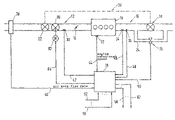
- FIG. 1 shows a general diagram of an internal combustion engine having an exhaust gas turbocharger.
- FIG. 2 shows a flow chart of a control of the internal combustion engine.
- FIG. 3 shows a general diagram of an internal combustion engine having an exhaust gas turbocharger and an electrical auxiliary charger.
- FIG. 4 shows an additional flow chart illustrating a control of the internal combustion engine.
- an internal combustion engine 10 which includes an intake system 12 having a throttle valve 14 , and an exhaust gas system 16 .
- Turbine 18 of an exhaust gas turbocharger is situated in exhaust gas system 16 , and the turbine is connected to compressor 22 , which is situated at the intake manifold, via a mechanical connection 20 .
- An electrically actuatable valve 26 is provided in a bypass duct 24 around turbine 18 of the exhaust gas turbocharger.
- Various sensors are installed for detecting different performance quantities in the region of the internal combustion engine. A selection of these sensors is illustrated in FIG.
- an air mass flow meter 28 an intake manifold pressure sensor 30 , an engine rotational speed sensor 32 , an exhaust gas pressure sensor 34 , and an exhaust gas temperature sensor 36 .
- An electronic controller 38 is also illustrated which receives lines from the above-mentioned sensors: a line 40 from air mass flow meter 28 , a line 42 from intake manifold pressure sensor 30 , a line 44 from rotational speed sensor 32 , a line 46 from exhaust gas pressure sensor 34 , and a line 48 from exhaust gas temperature sensor 36 .
- Control unit 38 also has an output line 50 used for controlling electrically actuatable valve 26 .
- additional input and output lines are provided which are necessary for controlling the internal combustion engine.
- Input lines 52 through 56 connect control unit 38 to sensors such as lambda probes, temperature sensors, etc., while output lines 58 through 62 lead to injectors, ignition output stages, throttle valve actuators, exhaust gas recirculation valves, etc.
- actuating element 26 is a servomotor that, at the location of the aneroid capsule and the timing valve, moves the linkage which adjusts the cross section of bypass line 24 .
- the procedure described below may also be used in systems having another actuator design, such as for electrically actuatable valves, for example.
- actuating element 26 is actuated depending on the exhaust gas volume flow, thereby creating a pilot control for the boost pressure regulation which simulates the counter-coupling characteristics.
- the volume flow of the exhaust gas, at which the setpoint boost pressure is established is calculated as a function of the engine rotational speed and the setpoint boost pressure. In the preferred exemplary embodiment this is achieved by a characteristics map, in which parameters are stored which take into account the mechanical and geometric characteristics of the turbocharger system.
- the exhaust gas volume flow produced by the engine is also calculated.
- the difference between the setpoint exhaust gas volume flow and the instantaneous exhaust gas volume flow results in the exhaust gas volume flow which should pass through the bypass to the turbine.
- This volume flow is modulated by the output signal from the boost pressure regulator, which is interpreted as a differential volume flow.
- the volume flow calculated from the difference between the setpoint and the actual volume flow, plus that calculated by the boost pressure regulator, is evaluated to determine the position of the electrical actuator.
- a characteristic line for example, is provided in which the volume flow is converted to an actuating signal.
- the illustrated pilot control over the exhaust gas volume flow has counter-coupling characteristics, as the result of which the exhaust gas volume flow produced by the engine is taken into account.
- the turbine rotational speed increases, and thus the rotational speed of the compressor situated on the intake side increases as well. This causes an increase in the boost pressure and the exhaust gas volume flow.
- the calculation and evaluation of the exhaust gas volume flow takes this into account in the control, since the pilot control then increases the cross section of the bypass opening. The exhaust gas turbocharger thus remains stable.
- the boost pressure regulator itself only performs corrections on a stable system.
- a boost pressure regulator it is advantageously sufficient to use a conventional, robust, and easily usable regulator, such as a regulator having a proportional, integral, and differential response, which is also used for actuators with counter-coupling characteristics, as previously mentioned.
- the pilot control itself operates in such a way that the cross section of the bypass opening is not constant as the exhaust gas volume flow increases, but instead increases even when the regulator is switched off.
- the above-described procedure is implemented in the preferred exemplary embodiment as a program on a microcomputer which is part of control unit 38 .
- the program on the microcomputer includes the necessary commands for performing the procedure.
- FIG. 2 shows a flow chart of such a program, the individual blocks representing programs, subprograms, or program steps, in particular commands or a summation of commands, whereas the connecting lines represent the information flow.
- a setpoint volume flow VSTUS over the turbine is calculated as a function of engine rotational speed nmot and setpoint boost pressure plsol. In the preferred exemplary embodiment, this is carried out using a characteristics map, and in another exemplary embodiment, using calculation steps. Essentially, the setpoint volume flow will increase with increasing setpoint boost pressure and increasing rotational speed.
- the setpoint boost pressure itself is determined from a setpoint pressure ratio between the pressure upstream and the pressure downstream from the compressor, which in turn depends on the engine rotational speed.
- a regulating algorithm 108 determines an output variable VSBYST as a function of its input variable.
- the input variable is a difference ⁇ P which is generated in node 110 .
- the setpoint boost pressure and the actual boost pressure PLIST measured by a boost pressure sensor are compared, and the resulting difference is sent to the regulator.
- the regulating algorithm then generates the output variable, which in node 106 corrects pilot control variable ⁇ VS.
- the correction is carried out as an addition, for example.
- the corrected pilot control variable ⁇ VS+VSBYST is converted to an actuating signal for the actuator of the exhaust gas turbocharger. In the preferred exemplary embodiment this is performed using a characteristics map, which assigns an output variable ⁇ to the input variable.
- a control variable having quantity ⁇ as a parameter is output by the microcomputer or the control unit for actuating the valve or actuator of the charger, which sets a volume flow in the bypass of the turbine. This volume flow corresponds to the volume flow according to the pilot control plus the regulating correction.
- a turbocharger system which in addition to the mechanical exhaust gas turbocharger has an electrical auxiliary charger.
- One such system is illustrated in the general diagram in FIG. 3 .
- the system illustrated in FIG. 1 is supplemented by an auxiliary supercharger 80 , driven by an electric motor, which is situated in the direction of flow downstream from compressor 22 and upstream from throttle valve 14 in the induction tract of internal combustion engine 10 .
- This auxiliary supercharger is driven by an electric motor 82 which is supplied with an actuating signal by controller 38 via an output line 84 .
- the other components and lines correspond to those illustrated in FIG. 1 , and therefore are provided with the same reference numbers and have the same function.
- One such electrical auxiliary supercharger is connected in series to the exhaust gas turbocharger because of the delayed response characteristic of the exhaust gas turbocharger, and is generally operated when acceleration is requested.
- the delayed response characteristic is thus compensated for during acceleration, and operation is optimized.
- the operating time of the electrical auxiliary charger which consumes resources of the motor vehicle and in particular greatly increases the load on the battery, should be minimized. It has been shown that this minimization may be achieved when the electrical compressor is operating, if the instantaneous exhaust gas volume flow is less than the flow demand of the turbine. These variables are available from the above-mentioned pilot control.
- Another criterion for operating the electrical auxiliary compressor which may be used in addition to that described above, is that a setpoint boost pressure is required which exceeds the base boost pressure.
- the base boost pressure is the pressure which results without special actuation of the exhaust gas turbocharger as a consequence of the air flow to the internal combustion engine.
- the auxiliary compressor is operated only until the instantaneous exhaust gas volume flow reaches the flow demand of the turbine.
- the operating time of the auxiliary compressor, and thus the load on the battery, is thereby minimized.
- the reason for this is that the exhaust gas turbocharger itself has a co-coupling response.
- the turbine rotates more rapidly, the compressor rotates with the turbine, and the boost pressure increases.
- the exhaust gas volume flow increases, which once again results in more rapid rotation of the turbine.
- boost pressure increasingly more exhaust gas must be diverted around the turbine so that the turbine does not overspeed. This is accomplished by the above-mentioned pilot control, as described above.
- no auxiliary compression by the electrical auxiliary compressor is necessary, since the exhaust gas turbocharger then provides sufficient boost pressure through its co-coupling response.
- suitable measures which specify the operating condition for the electrical auxiliary compressor are important. This is deduced from the above-described pilot control of the exhaust gas turbocharger actuator.
- the exhaust gas volume flow is calculated there from the measured or modeled variables of air mass flow rate, exhaust gas temperature, and exhaust gas pressure.
- the volume flow demand required for starting the exhaust gas turbocharger is determined. This is either specified as a fixed value or, as described above, is determined from the boost pressure and rotational speed. If the instantaneous exhaust gas volume flow is greater than the flow demand of the turbine, the difference between the two flows is diverted around the turbine via the waste gate. Overspeeding of the turbine is thus prevented.
- the auxiliary compressor is not operated until, in addition to the operating requirement deduced from the exhaust gas flow, there is a requirement for activation of the boost pressure regulation, i.e., when the setpoint boost pressure exceeds the base boost pressure.
- the auxiliary compressor always switches off at the same exhaust gas volume flow under various operating conditions (load, rotational speed, for example).
- the operating time of the auxiliary compressor is optimized.
- an inverter 200 For activation of the electrical auxiliary supercharger an inverter 200 is provided which leads to a switching element 202 , which preferably exhibits hysteresis. If the inverted volume flow ⁇ VS exceeds the specified limit, an operating condition signal B_SCEB is generated. If the volume flow falls below an additional threshold, this conditional signal is reset. The threshold is selected so that resetting is performed when the instantaneous exhaust gas volume flow reaches the setpoint volume flow, or has exceeded it by an amount that is greater than a specified quantity. The auxiliary supercharger is thus switched on when the exhaust gas volume flow is less than the setpoint volume flow.
- a logical AND link 204 is provided in which the conditional signal as described above is compared to an additional conditional signal B_LDR. This is set when boost pressure regulation is requested, i.e., when the setpoint boost pressure exceeds the base boost pressure. If both signals are present, a conditional signal B_SCE is output which results in activation of the electrical auxiliary charger. This auxiliary supercharger is then actuated either by a fixed specified actuating signal or, if required, according to the actual boost pressure, air flow, and/or rotational speed of the engine, etc.
- volume flow rates are used instead of volume flow rates.
Abstract
Description
VSABG=k·ML·TABG/PABG
where k is a constant.
Claims (12)
Applications Claiming Priority (3)
| Application Number | Priority Date | Filing Date | Title |
|---|---|---|---|
| DE10145038.9 | 2001-09-13 | ||
| DE10145038A DE10145038A1 (en) | 2001-09-13 | 2001-09-13 | Method and device for operating at least one supercharger of an internal combustion engine |
| PCT/DE2002/002683 WO2003027464A1 (en) | 2001-09-13 | 2002-07-20 | Method and device for operating at least one turbocharger on an internal combustion engine |
Publications (2)
| Publication Number | Publication Date |
|---|---|
| US20050056012A1 US20050056012A1 (en) | 2005-03-17 |
| US7540148B2 true US7540148B2 (en) | 2009-06-02 |
Family
ID=7698842
Family Applications (1)
| Application Number | Title | Priority Date | Filing Date |
|---|---|---|---|
| US10/489,926 Expired - Fee Related US7540148B2 (en) | 2001-09-13 | 2002-07-20 | Method and device for operating at least one turbocharger on an internal combustion engine |
Country Status (5)
| Country | Link |
|---|---|
| US (1) | US7540148B2 (en) |
| EP (1) | EP1427929B1 (en) |
| JP (1) | JP4146341B2 (en) |
| DE (2) | DE10145038A1 (en) |
| WO (1) | WO2003027464A1 (en) |
Cited By (15)
| Publication number | Priority date | Publication date | Assignee | Title |
|---|---|---|---|---|
| US20080053091A1 (en) * | 2005-02-16 | 2008-03-06 | Pierre Barthelet | Turbocharging Device and Control Method for Controlling the Turbocharging Device |
| US20080168771A1 (en) * | 2006-09-13 | 2008-07-17 | Ford Global Technologies, Llc | Method for Determining the Exhaust Back Pressure Upstream of a Turbine of an Exhaust-Driven Turbocharger |
| US20090094009A1 (en) * | 2007-10-04 | 2009-04-09 | Martin Muller | System and method for modeling of turbo-charged engines and indirect measurement of turbine and waste-gate flow and turbine efficiency |
| US20100228464A1 (en) * | 2007-09-24 | 2010-09-09 | Knorr-Bremse Systeme Fuer Nutzfahrzeuge Gmbh | Method and Device for Controlling a Suction Pressure of an Internal Combustion Engine |
| US20100304627A1 (en) * | 2009-04-01 | 2010-12-02 | Morvillo Robert A | Ventilation control system |
| US20110067395A1 (en) * | 2009-09-22 | 2011-03-24 | Eaton Corporation | Method of controlling an engine during transient operating conditions |
| US20110094480A1 (en) * | 2009-10-28 | 2011-04-28 | Eaton Corporation | Control Strategy for an Engine |
| US20130305710A1 (en) * | 2008-10-01 | 2013-11-21 | Honda Motor Co., Ltd. | Wastegate Control System And Method |
| US20140034026A1 (en) * | 2011-04-18 | 2014-02-06 | Toyota Jidosha Kabushiki Kaisha | Control device for supercharged engine |
| US20150240826A1 (en) * | 2012-09-11 | 2015-08-27 | IFP Energies Nouvelles | Method of determining a pressure upstream of a compressor for an engine equipped with double supercharging |
| US9551286B2 (en) | 2011-04-22 | 2017-01-24 | Borgwarner Inc. | Turbocharger boost control using exhaust pressure estimated from engine cylinder pressure |
| US9840972B2 (en) | 2011-05-25 | 2017-12-12 | Eaton Corporation | Supercharger-based twin charging system for an engine |
| US20190010881A1 (en) * | 2017-07-07 | 2019-01-10 | GM Global Technology Operations LLC | Vehicle turbocharger systems and methods with improved aftertreatment activation |
| US11098640B2 (en) | 2017-08-03 | 2021-08-24 | Volkswagen Aktiengesellschaft | Method for determining a basic boost pressure of a gas conducting system of an internal combustion engine, and engine controller for carrying out a method of this type |
| US11396842B2 (en) | 2019-04-09 | 2022-07-26 | Volkswagen Aktiengesellschaft | Method and devices for operating an internal combustion engine having a supercharging system |
Families Citing this family (32)
| Publication number | Priority date | Publication date | Assignee | Title |
|---|---|---|---|---|
| JP2004162676A (en) * | 2002-11-15 | 2004-06-10 | Yamaha Marine Co Ltd | Engine intake device |
| DE10305646B4 (en) * | 2003-02-11 | 2005-02-03 | Siemens Ag | Method for controlling the boost pressure in an internal combustion engine with turbocharger |
| DE10319347A1 (en) * | 2003-04-30 | 2004-11-18 | Robert Bosch Gmbh | Method and device for operating an internal combustion engine |
| DE10320277A1 (en) * | 2003-05-07 | 2004-12-02 | Robert Bosch Gmbh | Method and device for operating an internal combustion engine |
| DE60314512T2 (en) * | 2003-07-30 | 2008-03-20 | Ford Global Technologies, LLC, A Subsidiary of Ford Motor Company, Dearborn | Boost pressure control for an internal combustion engine |
| JP2005329850A (en) * | 2004-05-20 | 2005-12-02 | Yamaha Marine Co Ltd | Water-cooling structure of outboard engine |
| EP1619367A1 (en) * | 2004-07-19 | 2006-01-25 | Ford Global Technologies, LLC, A subsidary of Ford Motor Company | Method and apparatus for controlling an electric booster of an internal combustion engine |
| JP2006274831A (en) * | 2005-03-28 | 2006-10-12 | Denso Corp | Control device for internal combustion engine with turbocharger |
| DE102005016392B3 (en) * | 2005-04-09 | 2006-09-07 | Daimlerchrysler Ag | Regulating process for exhaust gas supercharger involves taking reliable maximum revs figure as actual operating point of compressor or engine |
| DE102005056011A1 (en) * | 2005-11-24 | 2007-06-06 | Volkswagen Ag | Internal combustion engine for motor vehicle, has exhaust system and exhaust gas turbocharger whereby disperse-outlet of turbine is connected with first exhaust gas flux |
| JP2007285229A (en) * | 2006-04-18 | 2007-11-01 | Yamaha Marine Co Ltd | Outboard motor |
| JP4729446B2 (en) * | 2006-06-29 | 2011-07-20 | キャタピラー エス エー アール エル | Work machine output control device and work machine output control method |
| US20080098734A1 (en) * | 2006-10-27 | 2008-05-01 | Jan-Ola Olsson | Engine Control Method |
| JP4797976B2 (en) * | 2006-12-26 | 2011-10-19 | 日産自動車株式会社 | Turbocharger control device and control method |
| US7721539B2 (en) * | 2007-05-01 | 2010-05-25 | Cummins Inc. | System for controlling engine fueling to limit engine output power |
| US7788922B2 (en) * | 2007-10-04 | 2010-09-07 | Delphi Technologies, Inc. | System and method for model based boost control of turbo-charged engines |
| US9109546B2 (en) * | 2009-01-21 | 2015-08-18 | Cummins Inc. | System and method for operating a high pressure compressor bypass valve in a two stage turbocharger system |
| FR2942000A3 (en) * | 2009-02-12 | 2010-08-13 | Renault Sas | Supercharging device for internal-combustion engine of vehicle, has pre-positioning module for receiving and processing measurement of supercharging parameter according to mechanical characteristics of actuator mechanism |
| FR2948977A3 (en) * | 2009-08-07 | 2011-02-11 | Renault Sa | Air intake system operating method for e.g. diesel engine of motor vehicle, involves changing from exhaust manifold pressure regulation state to intake manifold pressure regulation state, when absolute value becomes less than threshold |
| US9206734B2 (en) * | 2010-03-17 | 2015-12-08 | Toyota Jidosha Kabushiki Kaisha | Control apparatus for internal combustion engine |
| JP5420013B2 (en) * | 2012-04-20 | 2014-02-19 | 三菱電機株式会社 | Control device and control method for internal combustion engine |
| FR2995355B1 (en) * | 2012-09-11 | 2017-03-10 | Ifp Energies Now | METHOD FOR CONTROLLING A THERMAL MOTOR EQUIPPED WITH A DOUBLE SUPER-POWER |
| FR2998924B1 (en) * | 2012-11-30 | 2014-11-21 | IFP Energies Nouvelles | METHOD FOR CONTROLLING A THERMAL MOTOR EQUIPPED WITH A DOUBLE SUPER-POWER |
| DE102014213070A1 (en) * | 2014-07-04 | 2016-01-07 | Mahle International Gmbh | Internal combustion engine |
| JP6478273B2 (en) | 2015-04-08 | 2019-03-06 | ボッシュ株式会社 | Control device for supercharged internal combustion engine and control method therefor |
| JP6462504B2 (en) | 2015-06-18 | 2019-01-30 | ボッシュ株式会社 | Control device for supercharged internal combustion engine and control method therefor |
| JP6625837B2 (en) | 2015-06-29 | 2019-12-25 | ロベルト・ボッシュ・ゲゼルシャフト・ミト・ベシュレンクテル・ハフツングRobert Bosch Gmbh | EGR control method and EGR device |
| JP6453177B2 (en) * | 2015-07-02 | 2019-01-16 | ボッシュ株式会社 | Control device and control method for internal combustion engine |
| DE102015214039A1 (en) | 2015-07-24 | 2017-01-26 | Volkswagen Aktiengesellschaft | Method and control device for operating a drive arrangement |
| JP6330749B2 (en) * | 2015-07-29 | 2018-05-30 | マツダ株式会社 | Engine control device |
| CN106555684B (en) * | 2015-09-29 | 2019-09-03 | 长城汽车股份有限公司 | Vehicle, two-step supercharging control system and its control method |
| FR3085446B1 (en) * | 2018-08-29 | 2021-05-21 | Psa Automobiles Sa | GEOMETRY CONTROL INSTRUCTIONS FOR A TURBOCOMPRESSOR TURBINE ON A COMBUSTION ENGINE |
Citations (23)
| Publication number | Priority date | Publication date | Assignee | Title |
|---|---|---|---|---|
| US2492485A (en) * | 1945-02-12 | 1949-12-27 | Cons Vultee Aircraft Corp | Injection system for internal-combustion engines |
| US4392352A (en) * | 1978-05-27 | 1983-07-12 | Robert Bosch Gmbh | Apparatus for regulating turbochargers and internal combustion engines associated therewith |
| US4467608A (en) * | 1981-05-08 | 1984-08-28 | Nippon Soken, Inc. | Control method and apparatus for an internal combustion engine with a turbocharger |
| JPH01110832A (en) | 1987-07-03 | 1989-04-27 | Mitsubishi Motors Corp | Output control of internal combustion engine equipped with turbocharger |
| DE19708721A1 (en) | 1997-03-04 | 1998-09-17 | Man Nutzfahrzeuge Ag | Turbocharger system for IC engine |
| US5816047A (en) * | 1996-09-03 | 1998-10-06 | Dresser Industries, Inc. | Electronically controlled wastegate valve for a turbo charger |
| US6029452A (en) | 1995-11-15 | 2000-02-29 | Turbodyne Systems, Inc. | Charge air systems for four-cycle internal combustion engines |
| JP2000110573A (en) | 1998-09-30 | 2000-04-18 | Aisin Seiki Co Ltd | Variable capacity turbo charger |
| US6058708A (en) | 1997-07-29 | 2000-05-09 | Siemens Aktiengesellschaft | Device for controlling an internal combustion engine |
| US6076352A (en) * | 1996-01-16 | 2000-06-20 | Toyota Jidosha Kabushiki Kaisha | Supercharging pressure control device |
| US6161384A (en) * | 1994-05-02 | 2000-12-19 | Waukesha Engine Division, Dresser Equipment Group, Inc. | Turbocharger control management system throttle reserve control |
| EP1070837A2 (en) | 1999-07-23 | 2001-01-24 | Steyr-Nutzfahrzeuge Aktiengesellschaft | Device and method for increasing power of a turbocharged internal combustion engine |
| DE19935901A1 (en) | 1999-07-30 | 2001-02-01 | Bosch Gmbh Robert | Internal combustion engine regulation method involves delaying charging pressure demand involves specifying transfer characteristic of regulator depending on operating parameters |
| DE19936269A1 (en) | 1999-07-31 | 2001-02-08 | Bayerische Motoren Werke Ag | Manipulated variable control method for adjustable motor-vehicle units, such as turbo-charger boost pressure, requires dynamic correction of precontrol or pilot variable with defined control state at working point |
| US6354078B1 (en) * | 1996-02-22 | 2002-03-12 | Volvo Personvagnar Ab | Device and method for reducing emissions in catalytic converter exhaust systems |
| US6474323B1 (en) * | 1997-12-16 | 2002-11-05 | Servoject Products International | Optimized lambda and compression temperature control for compression ignition engines |
| US6662562B2 (en) * | 2000-03-07 | 2003-12-16 | Robert Bosch Gmbh | Method and device for regulating the boost pressure of an internal combustion engine |
| US6688104B2 (en) * | 2001-07-28 | 2004-02-10 | Robert Bosch Gmbh | Method and device for operating an electrical supercharger |
| US6705084B2 (en) * | 2001-07-03 | 2004-03-16 | Honeywell International Inc. | Control system for electric assisted turbocharger |
| US6732523B2 (en) * | 2000-07-07 | 2004-05-11 | Siemens Aktiengesellschaft | Method for controlling a charge pressure in an internal combustion engine with an exhaust gas turbocharger |
| US6751956B2 (en) * | 2002-01-23 | 2004-06-22 | Daimlerchrysler Ag | Internal combustion engine having an exhaust-gas turbocharger and method for operating such an internal combustion engine |
| US20050097945A1 (en) * | 2003-11-07 | 2005-05-12 | Flores Pio T. | Method for controlling at least one actuator in a mass flow duct |
| US20080104957A1 (en) * | 2005-04-05 | 2008-05-08 | Christian Birkner | Apparatus for Controlling an Internal Combustion Engine Having an Exhaust Gas Turbocharger and an Exhaust Gas Recirculation Apparatus |
-
2001
- 2001-09-13 DE DE10145038A patent/DE10145038A1/en not_active Withdrawn
-
2002
- 2002-07-20 US US10/489,926 patent/US7540148B2/en not_active Expired - Fee Related
- 2002-07-20 JP JP2003531001A patent/JP4146341B2/en not_active Expired - Fee Related
- 2002-07-20 DE DE50209730T patent/DE50209730D1/en not_active Expired - Lifetime
- 2002-07-20 WO PCT/DE2002/002683 patent/WO2003027464A1/en active IP Right Grant
- 2002-07-20 EP EP02758110A patent/EP1427929B1/en not_active Expired - Lifetime
Patent Citations (24)
| Publication number | Priority date | Publication date | Assignee | Title |
|---|---|---|---|---|
| US2492485A (en) * | 1945-02-12 | 1949-12-27 | Cons Vultee Aircraft Corp | Injection system for internal-combustion engines |
| US4392352A (en) * | 1978-05-27 | 1983-07-12 | Robert Bosch Gmbh | Apparatus for regulating turbochargers and internal combustion engines associated therewith |
| US4467608A (en) * | 1981-05-08 | 1984-08-28 | Nippon Soken, Inc. | Control method and apparatus for an internal combustion engine with a turbocharger |
| JPH01110832A (en) | 1987-07-03 | 1989-04-27 | Mitsubishi Motors Corp | Output control of internal combustion engine equipped with turbocharger |
| US6161384A (en) * | 1994-05-02 | 2000-12-19 | Waukesha Engine Division, Dresser Equipment Group, Inc. | Turbocharger control management system throttle reserve control |
| US6029452A (en) | 1995-11-15 | 2000-02-29 | Turbodyne Systems, Inc. | Charge air systems for four-cycle internal combustion engines |
| US6076352A (en) * | 1996-01-16 | 2000-06-20 | Toyota Jidosha Kabushiki Kaisha | Supercharging pressure control device |
| US6354078B1 (en) * | 1996-02-22 | 2002-03-12 | Volvo Personvagnar Ab | Device and method for reducing emissions in catalytic converter exhaust systems |
| US5816047A (en) * | 1996-09-03 | 1998-10-06 | Dresser Industries, Inc. | Electronically controlled wastegate valve for a turbo charger |
| DE19708721A1 (en) | 1997-03-04 | 1998-09-17 | Man Nutzfahrzeuge Ag | Turbocharger system for IC engine |
| US6058708A (en) | 1997-07-29 | 2000-05-09 | Siemens Aktiengesellschaft | Device for controlling an internal combustion engine |
| US6474323B1 (en) * | 1997-12-16 | 2002-11-05 | Servoject Products International | Optimized lambda and compression temperature control for compression ignition engines |
| JP2000110573A (en) | 1998-09-30 | 2000-04-18 | Aisin Seiki Co Ltd | Variable capacity turbo charger |
| EP1070837A2 (en) | 1999-07-23 | 2001-01-24 | Steyr-Nutzfahrzeuge Aktiengesellschaft | Device and method for increasing power of a turbocharged internal combustion engine |
| DE19935901A1 (en) | 1999-07-30 | 2001-02-01 | Bosch Gmbh Robert | Internal combustion engine regulation method involves delaying charging pressure demand involves specifying transfer characteristic of regulator depending on operating parameters |
| DE19936269A1 (en) | 1999-07-31 | 2001-02-08 | Bayerische Motoren Werke Ag | Manipulated variable control method for adjustable motor-vehicle units, such as turbo-charger boost pressure, requires dynamic correction of precontrol or pilot variable with defined control state at working point |
| US6662562B2 (en) * | 2000-03-07 | 2003-12-16 | Robert Bosch Gmbh | Method and device for regulating the boost pressure of an internal combustion engine |
| US6732523B2 (en) * | 2000-07-07 | 2004-05-11 | Siemens Aktiengesellschaft | Method for controlling a charge pressure in an internal combustion engine with an exhaust gas turbocharger |
| US6705084B2 (en) * | 2001-07-03 | 2004-03-16 | Honeywell International Inc. | Control system for electric assisted turbocharger |
| US6688104B2 (en) * | 2001-07-28 | 2004-02-10 | Robert Bosch Gmbh | Method and device for operating an electrical supercharger |
| US6751956B2 (en) * | 2002-01-23 | 2004-06-22 | Daimlerchrysler Ag | Internal combustion engine having an exhaust-gas turbocharger and method for operating such an internal combustion engine |
| US20050097945A1 (en) * | 2003-11-07 | 2005-05-12 | Flores Pio T. | Method for controlling at least one actuator in a mass flow duct |
| US7174777B2 (en) * | 2003-11-07 | 2007-02-13 | Robert Bosch Gmbh | Method for controlling at least one actuator in a mass flow duct |
| US20080104957A1 (en) * | 2005-04-05 | 2008-05-08 | Christian Birkner | Apparatus for Controlling an Internal Combustion Engine Having an Exhaust Gas Turbocharger and an Exhaust Gas Recirculation Apparatus |
Non-Patent Citations (2)
| Title |
|---|
| Automotive Handbook, Bosch 3rd ed., 1993, pp. 466-471. |
| Bosch, Automotive Handbook, Bosch 22nd edition., 1993, pp. 475-476. |
Cited By (24)
| Publication number | Priority date | Publication date | Assignee | Title |
|---|---|---|---|---|
| US20080053091A1 (en) * | 2005-02-16 | 2008-03-06 | Pierre Barthelet | Turbocharging Device and Control Method for Controlling the Turbocharging Device |
| US20080168771A1 (en) * | 2006-09-13 | 2008-07-17 | Ford Global Technologies, Llc | Method for Determining the Exhaust Back Pressure Upstream of a Turbine of an Exhaust-Driven Turbocharger |
| US7779633B2 (en) * | 2006-09-13 | 2010-08-24 | Ford Global Technologies, Llc | Method for determining the exhaust back pressure upstream of a turbine of an exhaust-driven turbocharger |
| US20100228464A1 (en) * | 2007-09-24 | 2010-09-09 | Knorr-Bremse Systeme Fuer Nutzfahrzeuge Gmbh | Method and Device for Controlling a Suction Pressure of an Internal Combustion Engine |
| US8037866B2 (en) * | 2007-09-24 | 2011-10-18 | Knorr-Bremse Systeme Fuer Nutzfahrzeuge Gmbh | Method and device for controlling a suction pressure of an internal combustion engine |
| US7748217B2 (en) * | 2007-10-04 | 2010-07-06 | Delphi Technologies, Inc. | System and method for modeling of turbo-charged engines and indirect measurement of turbine and waste-gate flow and turbine efficiency |
| US20090094009A1 (en) * | 2007-10-04 | 2009-04-09 | Martin Muller | System and method for modeling of turbo-charged engines and indirect measurement of turbine and waste-gate flow and turbine efficiency |
| US8919120B2 (en) * | 2008-10-01 | 2014-12-30 | Honda Motor Co., Ltd. | Wastegate control system and method |
| US20130305710A1 (en) * | 2008-10-01 | 2013-11-21 | Honda Motor Co., Ltd. | Wastegate Control System And Method |
| US20100304627A1 (en) * | 2009-04-01 | 2010-12-02 | Morvillo Robert A | Ventilation control system |
| US8814613B2 (en) * | 2009-04-01 | 2014-08-26 | Robert A. Morvillo | Ventilation control system |
| US20110067395A1 (en) * | 2009-09-22 | 2011-03-24 | Eaton Corporation | Method of controlling an engine during transient operating conditions |
| US20110094480A1 (en) * | 2009-10-28 | 2011-04-28 | Eaton Corporation | Control Strategy for an Engine |
| US8640458B2 (en) | 2009-10-28 | 2014-02-04 | Eaton Corporation | Control strategy for an engine |
| US20140034026A1 (en) * | 2011-04-18 | 2014-02-06 | Toyota Jidosha Kabushiki Kaisha | Control device for supercharged engine |
| US9175597B2 (en) * | 2011-04-18 | 2015-11-03 | Toyota Jidosha Kabushiki Kaisha | Control device for supercharged engine |
| US9551286B2 (en) | 2011-04-22 | 2017-01-24 | Borgwarner Inc. | Turbocharger boost control using exhaust pressure estimated from engine cylinder pressure |
| US9840972B2 (en) | 2011-05-25 | 2017-12-12 | Eaton Corporation | Supercharger-based twin charging system for an engine |
| US20150240826A1 (en) * | 2012-09-11 | 2015-08-27 | IFP Energies Nouvelles | Method of determining a pressure upstream of a compressor for an engine equipped with double supercharging |
| US9739281B2 (en) * | 2012-09-11 | 2017-08-22 | IFP Energies Nouvelles | Method of determining a pressure upstream of a compressor for an engine equipped with double supercharging |
| US20190010881A1 (en) * | 2017-07-07 | 2019-01-10 | GM Global Technology Operations LLC | Vehicle turbocharger systems and methods with improved aftertreatment activation |
| US10400693B2 (en) * | 2017-07-07 | 2019-09-03 | GM Global Technology Operations LLC | Vehicle turbocharger systems and methods with improved aftertreatment activation |
| US11098640B2 (en) | 2017-08-03 | 2021-08-24 | Volkswagen Aktiengesellschaft | Method for determining a basic boost pressure of a gas conducting system of an internal combustion engine, and engine controller for carrying out a method of this type |
| US11396842B2 (en) | 2019-04-09 | 2022-07-26 | Volkswagen Aktiengesellschaft | Method and devices for operating an internal combustion engine having a supercharging system |
Also Published As
| Publication number | Publication date |
|---|---|
| DE10145038A1 (en) | 2003-04-03 |
| WO2003027464A1 (en) | 2003-04-03 |
| EP1427929A1 (en) | 2004-06-16 |
| US20050056012A1 (en) | 2005-03-17 |
| DE50209730D1 (en) | 2007-04-26 |
| EP1427929B1 (en) | 2007-03-14 |
| JP4146341B2 (en) | 2008-09-10 |
| JP2005504210A (en) | 2005-02-10 |
Similar Documents
| Publication | Publication Date | Title |
|---|---|---|
| US7540148B2 (en) | Method and device for operating at least one turbocharger on an internal combustion engine | |
| US7210296B2 (en) | Method and device for controlling an electrically driven charger | |
| JP5680169B1 (en) | Control device and control method for internal combustion engine | |
| US6732523B2 (en) | Method for controlling a charge pressure in an internal combustion engine with an exhaust gas turbocharger | |
| JP5734478B1 (en) | Control device for an internal combustion engine with a supercharger | |
| EP3133273A1 (en) | Control device for a supercharged internal combustion engine | |
| JPH0343449B2 (en) | ||
| US20030010019A1 (en) | Method and device for regulating the boost pressure of an internal combustion engine | |
| EP0657636B1 (en) | Control system and method for turbocharged internal combustion engines | |
| JP4024423B2 (en) | Fuel injection amount control device for an internal combustion engine with a turbocharger | |
| CN110714844B (en) | Method for controlling a supercharging system | |
| US4709553A (en) | Method of and apparatus for controlling supercharge pressure for a turbocharger | |
| US7954319B2 (en) | Method and control unit for setting a turbine flow cross-section | |
| JP2006152821A (en) | Control system of internal combustion engine with supercharger | |
| GB2228768A (en) | Supercharging pressure control system for an engine with a turbocharger | |
| JP3105402B2 (en) | Supercharging pressure control method | |
| US11015538B2 (en) | Method for controlling a supercharging system | |
| JPH0476224A (en) | Supercharging pressure control method for turbocharger | |
| EP4191045B1 (en) | Supercharging pressure control method and supercharging pressure control device for internal combustion engine | |
| JP2986115B2 (en) | Control device for supercharged engine | |
| JPS6213730A (en) | Controller for variable displacement turbosupercharger | |
| JPH0476223A (en) | Supercharging pressure control method for turbocharger | |
| JPH0617661A (en) | Supercharged pressure control device for engine | |
| JPH048611B2 (en) |
Legal Events
| Date | Code | Title | Description |
|---|---|---|---|
| AS | Assignment |
Owner name: ROBERT BOSCH GMBH, GERMANY Free format text: ASSIGNMENT OF ASSIGNORS INTEREST;ASSIGNORS:WILD, ERNST;WEGENER, SABINE;HILD, RAINER;REEL/FRAME:015813/0736;SIGNING DATES FROM 20040503 TO 20040504 |
|
| STCF | Information on status: patent grant |
Free format text: PATENTED CASE |
|
| FPAY | Fee payment |
Year of fee payment: 4 |
|
| FPAY | Fee payment |
Year of fee payment: 8 |
|
| FEPP | Fee payment procedure |
Free format text: MAINTENANCE FEE REMINDER MAILED (ORIGINAL EVENT CODE: REM.); ENTITY STATUS OF PATENT OWNER: LARGE ENTITY |
|
| LAPS | Lapse for failure to pay maintenance fees |
Free format text: PATENT EXPIRED FOR FAILURE TO PAY MAINTENANCE FEES (ORIGINAL EVENT CODE: EXP.); ENTITY STATUS OF PATENT OWNER: LARGE ENTITY |
|
| STCH | Information on status: patent discontinuation |
Free format text: PATENT EXPIRED DUE TO NONPAYMENT OF MAINTENANCE FEES UNDER 37 CFR 1.362 |
|
| FP | Lapsed due to failure to pay maintenance fee |
Effective date: 20210602 |