US7563004B2 - Volumetric downlight light fixture - Google Patents
Volumetric downlight light fixture Download PDFInfo
- Publication number
- US7563004B2 US7563004B2 US11/653,781 US65378107A US7563004B2 US 7563004 B2 US7563004 B2 US 7563004B2 US 65378107 A US65378107 A US 65378107A US 7563004 B2 US7563004 B2 US 7563004B2
- Authority
- US
- United States
- Prior art keywords
- lens
- base member
- reflector assembly
- light source
- light
- Prior art date
- Legal status (The legal status is an assumption and is not a legal conclusion. Google has not performed a legal analysis and makes no representation as to the accuracy of the status listed.)
- Active, expires
Links
Images


Classifications
-
- F—MECHANICAL ENGINEERING; LIGHTING; HEATING; WEAPONS; BLASTING
- F21—LIGHTING
- F21S—NON-PORTABLE LIGHTING DEVICES; SYSTEMS THEREOF; VEHICLE LIGHTING DEVICES SPECIALLY ADAPTED FOR VEHICLE EXTERIORS
- F21S8/00—Lighting devices intended for fixed installation
- F21S8/02—Lighting devices intended for fixed installation of recess-mounted type, e.g. downlighters
-
- F—MECHANICAL ENGINEERING; LIGHTING; HEATING; WEAPONS; BLASTING
- F21—LIGHTING
- F21V—FUNCTIONAL FEATURES OR DETAILS OF LIGHTING DEVICES OR SYSTEMS THEREOF; STRUCTURAL COMBINATIONS OF LIGHTING DEVICES WITH OTHER ARTICLES, NOT OTHERWISE PROVIDED FOR
- F21V13/00—Producing particular characteristics or distribution of the light emitted by means of a combination of elements specified in two or more of main groups F21V1/00 - F21V11/00
- F21V13/02—Combinations of only two kinds of elements
- F21V13/04—Combinations of only two kinds of elements the elements being reflectors and refractors
-
- F—MECHANICAL ENGINEERING; LIGHTING; HEATING; WEAPONS; BLASTING
- F21—LIGHTING
- F21V—FUNCTIONAL FEATURES OR DETAILS OF LIGHTING DEVICES OR SYSTEMS THEREOF; STRUCTURAL COMBINATIONS OF LIGHTING DEVICES WITH OTHER ARTICLES, NOT OTHERWISE PROVIDED FOR
- F21V5/00—Refractors for light sources
- F21V5/02—Refractors for light sources of prismatic shape
-
- F—MECHANICAL ENGINEERING; LIGHTING; HEATING; WEAPONS; BLASTING
- F21—LIGHTING
- F21V—FUNCTIONAL FEATURES OR DETAILS OF LIGHTING DEVICES OR SYSTEMS THEREOF; STRUCTURAL COMBINATIONS OF LIGHTING DEVICES WITH OTHER ARTICLES, NOT OTHERWISE PROVIDED FOR
- F21V7/00—Reflectors for light sources
- F21V7/0091—Reflectors for light sources using total internal reflection
-
- F—MECHANICAL ENGINEERING; LIGHTING; HEATING; WEAPONS; BLASTING
- F21—LIGHTING
- F21Y—INDEXING SCHEME ASSOCIATED WITH SUBCLASSES F21K, F21L, F21S and F21V, RELATING TO THE FORM OR THE KIND OF THE LIGHT SOURCES OR OF THE COLOUR OF THE LIGHT EMITTED
- F21Y2103/00—Elongate light sources, e.g. fluorescent tubes
- F21Y2103/30—Elongate light sources, e.g. fluorescent tubes curved
- F21Y2103/37—U-shaped
Definitions
- the present invention generally relates to light fixtures for illuminating architectural spaces, and, more particularly, to downlight light fixtures for illuminating the desired space.
- a light fixture presently used in a typical office environment comprises a troffer with at least one fluorescent lamp and a lens having prismatic elements for distributing the light. Also known are light fixtures that use shaped reflectors to provide a desired light distribution.
- the choice of light fixture will depend on the objectives of the lighting designer for a particular application and the economic resources available. To meet his or her design objectives, the lighting designer, when choosing a light fixture, will normally consider a variety of factors including aesthetic appearance, desired light distribution characteristics, efficiency, lumen package, maintenance and sources of brightness that can detract from visual comfort and productivity.
- the fluorescent lamp has long been the light source of choice among lighting designers in many commercial applications, particularly for indoor office lighting.
- Some conventional fluorescent lamps have a significant drawback in that the lamp surface is bright when compared to a lamp of larger diameter. The consequence of such bright surfaces is quite severe in applications where the lamps may be viewed directly, such as, for example a conventional downlight.
- downlight fixtures employing such lamps are very uncomfortable and produce direct and reflected glare that impairs the comfort of the lighting environment.
- lamps have been devised to substantially diffuse the intensity of the lamp to mitigate problems associated with light sources of high surface brightness.
- the present invention overcomes the above-described disadvantages of downlight fixtures by providing a configuration that appears to a viewer as though it has a source of lower brightness, but which otherwise permits the light fixture to advantageously and efficiently distribute light generated by the selected lamp.
- the light fixture of the present invention reduces distracting direct glare associated with high brightness light sources used in direct or direct light fixtures. This reduction in glare is accomplished without the addition of lamps and the added costs associated therewith.
- the present invention relates to a volumetric downlight light fixture for efficiently distributing light emitted by a light source into an area to be illuminated.
- the light fixture comprises a reflector assembly that supports the light source.
- the light fixture may also include a lens assembly positioned with respect to a portion of the reflector assembly to receive light emitted by the light source and distribute it such that glare is further reduced.
- the lens assembly receives and distributes substantially all of the light emitted by the light source.
- volumetric downlight light fixture for distributing generated light for distributing generated light
- Other systems, methods, features, and advantages of the volumetric downlight light fixture for distributing generated light will be or become apparent to one with skill in the art upon examination of the following figures and detailed description. It is intended that all such additional systems, methods, features, and advantages be included within this description, be within the scope of the volumetric downlight light fixture for distributing generated light, and be protected by the accompanying claims.
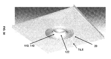
- FIG. 1 is a perspective view of one embodiment of a volumetric downlight light fixture of the present invention, showing the fixture mounted therein a ceiling tile.
- FIG. 2 is a bottom plan elevational view of the volumetric downlight light fixture of FIG. 1 .
- FIG. 3 is bottom plan elevational view of the volumetric downlight light fixture of FIG. 1 , showing the fixture mounted therein a ceiling tile.
- FIG. 4 is a side elevational view of the volumetric downlight light fixture of FIG. 3 .
- FIG. 5 is a cross-sectional view of the volumetric downlight light fixture of FIG. 3 , taken along line 5 - 5 .
- FIG. 6 is a perspective view of a second embodiment of a volumetric downlight light fixture of the present invention, showing the fixture mounted therein a ceiling tile.
- FIG. 7 is a bottom plan elevational view of the volumetric downlight light fixture of FIG. 6 .
- FIG. 8 is a bottom plan elevational view of the volumetric downlight light fixture of FIG. 6 , showing the fixture mounted therein a ceiling tile.
- FIG. 9 is a side elevational view of the volumetric downlight light fixture of FIG. 8 .
- FIG. 10 is a cross-sectional view of the volumetric downlight light fixture of FIG. 8 , taken along line 10 - 10 .
- FIG. 11 is a cross-sectional view of the volumetric downlight light fixture of FIG. 8 , taken along line 11 - 11 .
- FIG. 12 is a perspective view of a third embodiment of a volumetric downlight light fixture of the present invention, showing the fixture mounted therein a ceiling tile.
- FIG. 13 is a bottom plan elevational view of the volumetric downlight light fixture of FIG. 12 .
- FIG. 14 is a perspective view of a fourth embodiment of a volumetric downlight light fixture of the present invention, showing the fixture mounted therein a ceiling tile.
- FIG. 15 is a bottom plan elevational view of the volumetric downlight light fixture of FIG. 14 .
- FIG. 16 is a perspective view of a fifth embodiment of a volumetric downlight light fixture of the present invention, showing the fixture mounted therein a ceiling tile.
- FIG. 17 is a bottom plan elevational view of the volumetric downlight light fixture of FIG. 16 .
- FIG. 18 is a perspective view of a sixth embodiment of a volumetric downlight light fixture of the present invention, showing the fixture mounted therein a ceiling tile.
- FIG. 19 is a bottom plan elevational view of the volumetric downlight light fixture of FIG. 18 .
- FIG. 20 is a perspective view of a seventh embodiment of a volumetric downlight light fixture of the present invention, showing the fixture mounted therein a ceiling tile.
- FIG. 21 is a bottom plan elevational view of the volumetric downlight light fixture of FIG. 20 .
- FIG. 22 is a perspective view of an eighth embodiment of a volumetric downlight light fixture of the present invention, showing the fixture mounted therein a ceiling tile.
- FIG. 23 is a bottom plan elevational view of the volumetric downlight light fixture of FIG. 22 .
- FIG. 24 is a perspective view of a ninth embodiment of a volumetric downlight light fixture of the present invention, showing the fixture mounted therein a ceiling tile.
- FIG. 25 is a bottom plan elevational view of the volumetric downlight light fixture of FIG. 24 .
- FIG. 26 is a partial broken away perspective view of the volumetric downlight light fixture of FIG. 24 .
- FIG. 27 is a perspective view of a twelfth embodiment of a volumetric downlight light fixture of the present invention, showing the fixture mounted therein a ceiling tile.
- FIG. 28 is a bottom plan elevational view of the volumetric downlight light fixture of FIG. 27 .
- FIG. 29 is a partial broken away perspective view of the volumetric downlight light fixture of FIG. 27 .
- FIG. 30 is a perspective view of a thirteenth embodiment of a volumetric downlight light fixture of the present invention, showing the fixture mounted therein a ceiling tile.
- FIG. 31 is a bottom plan elevational view of the volumetric downlight light fixture of FIG. 30 .
- FIG. 32 is a partial broken away perspective view of the volumetric downlight light fixture of FIG. 30 .
- FIG. 33 is an enlarged partial sectional view of an exemplary lens assembly, showing one embodiment of an array of prismatic elements disposed on a surface of the lens.
- FIG. 34 is an enlarged partial sectional view of an exemplary lens assembly, showing an alternative embodiment of the array of prismatic elements.
- FIGS. 35 and 36 are enlarged partial sectional views of the lens assembly, showing still further alternative embodiments of the array of prismatic elements.
- FIG. 37 shows an enlarged partial cross-sectional view of one embodiment of the lens assembly of the present invention with the diffuser inlay in registration with a portion of the prismatic surface of the lens.
- FIG. 38 shows an exemplary path of a reverse ray of light, in a vertical plane transverse to a section of the prismatic elements of the lens assembly, entering the face of the lens, the face being oriented away from the light source.
- FIG. 39 shows an exemplary path of a reverse ray of light, in a vertical plane transverse to a section of the prismatic elements of the lens assembly, being rejected out of the face of the lens, the face being oriented away from the light source.
- FIG. 40 shows an exemplary path of a reverse ray of light, in a vertical plane parallel to the longitudinal axis of a linear embodiment of a prismatic element of the lens assembly, entering the face of the lens and being rejected out of the face of the lens, the face being oriented away from the light.
- FIG. 41 is a perspective view of the exemplary path of a reverse ray of light.
- Ranges can be expressed herein as from “about” one particular value, and/or to “about” another particular value. When such a range is expressed, another aspect includes from the one particular value and/or to the other particular value. Similarly, when values are expressed as approximations, by use of the antecedent “about,” it will be understood that the particular value forms another aspect. It will be further understood that the endpoints of each of the ranges are significant both in relation to the other endpoint, and independently of the other endpoint.
- the terms “optional” or “optionally” mean that the subsequently described event or circumstance may or may not occur, and that the description includes instances where said event or circumstance occurs and instances where it does not.
- a light fixture 10 of the present invention for illuminating an area includes a reflector assembly 20 for housing a light source 12 .
- Light emanating from the light source 12 is diffused by a lens assembly 100 that is positioned between the light source 12 and the area to be illuminated.
- the light source 12 may be a conventional fluorescent lamp, and in one aspect, the light source 12 can be a conventional compact fluorescent lamp.
- the reflector assembly 20 of the light fixture comprises a base member 22 that has a bottom peripheral edge 24 , and defines an opening 26 positioned in a central portion 38 of the base member.
- the base member further comprises a base surface 30 that generally extends from the bottom peripheral edge to the opening.
- the base member 22 can be formed from a single piece of material or from a plurality of adjoined pieces.
- the reflector assembly 20 of the light fixture can be formed from any code-compliant material.
- the base member of the reflector assembly can be formed from steel or aluminum.
- the peripheral edge 24 of the base member is positioned in a bottom plane Bp and the opening of the base member is positioned in a top plane T p that is spaced a predetermined distance from the bottom plane.
- at least a portion of the base surface 30 of the base member 22 forms a hollow 32 that extends inwardly in the transverse dimension away from the peripheral edge 24 of the base member.
- the light fixture of the present invention extends upwardly from the bottom plane toward the opening 26 to define an interior volume that is recessed from the peripheral edge of the base member.
- each formed hollow 32 preferably comprises a reflective surface 33 that extends generally between the central portion 38 and the peripheral edge 24 of the base member.
- at least a portion of each hollow 32 has a generally curved sectional shape such that such that portions of the hollow 32 form a generally curved reflective surface 35 for diffusely reflecting light received from the lens into the architectural space in a desired pattern.
- at least one transverse section of the hollow can have a barrel shape.
- at least a portion of each hollow 32 can have at least one planar portion.
- At least a portion of the hollow 32 of the base surface 30 of the base member can be painted or coated with a reflective material or formed from a reflective material.
- the reflective material may be substantially glossy or substantially flat.
- the reflective material is preferably matte white to diffusely reflect incident light.
- the central portion 38 of the light fixture is generally symmetrically positioned within the light fixture.
- the light source 12 is releaseably housed within a lamp housing that overlies the opening of the base member and is in operative communication with a light ballast.
- the reflector assembly is connected to the lamp housing. In one example, at least a portion of the light source 12 extends though the opening of the base member and into the interior volume of the hollow 32 .
- At least a portion of the reflective surface 33 of the hollow 32 has a plurality of male ridges 37 formed thereon. In an alternative aspect, at least a portion of the reflective surface 33 of the hollow 32 has a plurality of female grooves 39 formed therein. In another aspect, each male ridge or female groove 37 , 39 can extend substantially parallel to an adjoining male ridge or female groove. In operation, the ridges 37 or grooves 39 formed on the hollow 32 provide a diffusely reflecting surface.
- At least a portion of the base surface 30 of the base member 22 has the plurality of male ridges 37 formed thereon, which, at least partially, surround the opening of the central portion of the base member.
- at least a portion of the base surface 30 of the base member has the plurality of female grooves 39 formed thereon, which, at least partially, surround about the opening of the central portion of the base member.
- each ridge or groove 37 , 39 has a generally circular circumferential shape when viewed from a bottom elevational plan view.
- a respective ridge or groove that is positioned closer to the peripheral edge 24 has a larger diameter than a ridge or groove that is positioned closer to the opening 26 in the base member.
- the respective ridge or groove extend, at least partially, concentrically about the opening of the central portion of the base member.
- each ridge or groove 37 , 39 has a generally square or rectangular circumferential shape when viewed from a bottom elevational plan view.
- a respective ridge or groove that is positioned closer to the peripheral edge 24 has a larger circumferential shape than a ridge or groove that is positioned closer to the opening 26 in the base member.
- each respective ridge or groove extends, at least partially, about the opening of the central portion of the base member.
- each ridge or groove 37 , 39 have a generally oval circumferential shape when viewed from a bottom elevational plan view.
- a respective ridge or groove that is positioned closer to the peripheral edge 24 has a larger circumferential shape than a ridge or groove that is positioned closer to the opening 26 in the base member.
- each respective ridge or groove extends, at least partially, about the opening of the central portion of the base member.
- the base member has a longitudinal axis and at least a portion of the respective plurality of ridges or grooves 37 , 39 extends parallel to the longitudinal axis of the base member.
- each ridge or groove can have any desired geometric circumferential shape as long as each respective ridge or groove 37 , 39 that is positioned closer to the peripheral edge 24 of the base member has a larger circumferential shape than a ridge or groove that is positioned closer to the opening 26 in the base member.
- the respective ridge or groove extends, at least partially, about the opening of the central portion of the base member.
- the light source 12 can be positioned between a portion of the base surface of the base member and the lens assembly. In another aspect of the invention, the light source 12 can be positioned therein the opening of the reflector assembly 20 such that at least a portion of the light source is positioned above the top plane of the base member. Alternatively, the light source 12 can be positioned therein the opening of the reflector assembly such that the light source is positioned substantially about or above a portion of central portion of the base member In one aspect, and as shown in FIGS. 20-23 , the base member of the reflector assembly 20 can also comprise a first end face 50 and an opposed second end face 52 .
- Each of the end faces extends upwardly from the peripheral edge of the base member toward the central portion of the base member.
- Each end face has a face longitudinal axis that forms an obtuse angle with respect to the longitudinal axis of the base member 22 .
- the angled first and second end faces 50 , 52 optically alter the apparent perspective of the light fixture and aesthetically give the light fixture a deeper appearance.
- At least a portion of the respective side edges of the first and second end faces can be curved in shape.
- the juncture of the respective end faces and the side faces of the light fixture can form an angle relative to each other or can be smoothly curved.
- the face longitudinal axis of each of the first and second end faces 50 , 52 respectively forms an angle ⁇ of about and between 95° to 160° with respect to the base longitudinal axis of the base member 22 . More particularly, the face longitudinal axis of each of the first and second end faces respectively forms an angle ⁇ of about and between 100° to 150° with respect to the base longitudinal axis. Still more particularly, the face longitudinal axis of each of the first and second end faces respectively forms an angle ⁇ of about and between 100° to 135° with respect to the base longitudinal axis. In another aspect, the face longitudinal axis of each of the first and second end faces respectively forms an angle ⁇ of about 120° with respect to the base longitudinal axis. In yet another aspect, the respective obtuse angles formed between the face longitudinal axis of the first end face 50 and the face longitudinal axis of the second end face 52 and the base longitudinal axis of the base member 22 are substantially equal.
- first and second end faces 50 , 52 are contemplated.
- Each of the first and second end faces may be substantially planar or non-planar.
- portions of the first and second end faces are curved.
- the curved portions of the first and second end faces can be substantially concave or substantially convex.
- portions of the first and second end faces of the base member can also have male ridges 37 or female grooves 39 formed thereon.
- the lamp housing is configured to mount a conventional electrical contact or receptacle for detachably securing a selected end of the light source thereto. It is contemplated that the electrical contact can be mounted to any of the surfaces that define the interior of the lamp housing.
- the light fixture 10 also includes at least one conventional light ballast 76 constructed and arranged for electrically connecting the light source to an external power source. In one aspect, the at least one ballast 76 is mounted to a top surface of the light fixture.
- the lens assembly 100 of the present invention is constructed and arranged to direct light emitted by the light source 12 onto the area to be illuminated.
- a basic function of the lens assembly 100 is to diffuse the light from the light source 12 to effectively hide the light source 12 itself from view while reducing its brightness.
- one function of the lens assembly is to effectively become the source of light for the light fixture. This is accomplished in the preferred embodiment by providing the lens 110 of the lens assembly with a plurality of prismatic elements with short focal lengths. Because of the short focal lengths of the prismatic elements, the light from the light source is focused to parallel images very close to the surface of the lens at large angles of convergence. Because of the large angles of convergence, the images overlap and the light is essentially diffused. The diffused light is then either directed onto the surface to be illuminated without further reflection or is reflected by the reflective surfaces of the hollow 32 . Thus, the lens assembly provides a diffuse source of lowered brightness.
- the light source 12 is mounted in the opening of the base member and is recessed with respect to the peripheral edge 24 of the reflector assembly. This allows the lens 110 to be placed higher in the light fixture and provides geometric control of high-angle rays emanating from the lens. Thus, light rays produced at high viewing angles are physically blocked by the bottom peripheral edge of the light fixture. Further, the light fixture of the invention also optically controls glare. Thus, in this aspect, the light fixture of the invention prevents glare at high viewing angles through two mechanisms, geometrically and/or optically, depending on the viewer's respective position relative to lens assembly of the light fixture.
- the lens 110 of the lens assembly is positioned with respect to the reflector assembly 20 of the light fixture such that substantially all of the light emitted by the light source 12 passes through the lens 110 prior to impacting portions of the reflective surfaces 33 of the reflector assembly and/or prior to being dispersed into the surrounding area.
- the lens assembly 100 includes a lens 110 having a first end edge 112 , an opposed second end edge 113 , and a central lens portion 114 that extends between the first and second edges.
- the central lens portion 114 has a lens longitudinal axis that extends between the first and second end edges.
- the lens longitudinal axis is generally parallel to the light longitudinal axis of the light source 12 .
- the lens 110 has a generally circular, rectangular, square, or oval shape. Of course, other geometric shapes for the lens 110 are contemplated.
- the lens has a generally toric shape.
- the lens 110 can be made from any suitable, code-compliant material such as, for example, a polymer or plastic.
- the lens 110 can be constructed by extruding pellets of meth-acrylate or polycarbonates into the desired shape of the lens.
- the lens 110 can be a clear material or translucent material. In another aspect, the lens can be colored or tinted.
- At least a portion of the lens has a prismatic surface 116 on a face 118 of the lens that is either spaced from and facing toward the light source 12 or, alternatively, spaced from and facing away from the light source 12 .
- at least a portion of the lens 110 is curved in cross-section such that at least a portion of the face 118 of the central lens portion has a concave or convex shape relative to the light source.
- at least a portion of the lens is planar in cross-section.
- the lens 110 is positioned within the reflector assembly so that it is recessed above the bottom plane of the base member. In a further aspect, the lens is recessed within the reflector assembly such that a plane bisecting the peripheral edge of the base member and a tangential portion of the lens is oriented at an acute angle ⁇ to the generally horizontal bottom plane.
- the acute angle ⁇ is about and between 3° to 30°. More particularly, the acute angle ⁇ is about and between 05° to 20°. Still more particularly, the acute angle ⁇ is about and between 10° to 15°.
- the recessed position of the lens assembly within the reflector assembly provides for high angle control of light emitted by the light fixture in a vertical plane.
- an observer approaching the ceiling mounted light fixture of the present invention would not see the lens assembly until they passed into the lower viewing angles.
- portions of the reflector assembly act to block the view of the lens assembly from an observer at the higher viewing angles (i.e., the viewing angles closer to the horizontal ceiling plane).
- the prismatic surface 116 of the lens defines an array of elongated prismatic elements 120 .
- each prismatic element 122 thereof can extend linearly substantially longitudinally between the first and second edge edges 112 , 114 of the lens.
- each prismatic element 122 thereof can extend linearly at an angle relative to a lens longitudinal axis.
- each prismatic element thereof can extend generally transverse to the lens longitudinal axis.
- each prismatic element can have a generally circular circumferential shape in which each successive and adjacent prismatic element extends substantially parallel to its adjoining prismatic element.
- a respective prismatic element that is positioned closer to the outer edge of the lens has a larger diameter than a prismatic element that is positioned closer to the center of the lens.
- the respective prismatic elements extend, at least partially, concentrically about the center of the lens.
- each prismatic element can have a generally square or rectangular circumferential shape in which each successive and adjacent prismatic element extends substantially parallel to its adjoining prismatic element.
- a respective prismatic element that is positioned closer to the outer edge of the lens has a larger circumferential shape than a prismatic element that is positioned closer to the center of the lens.
- the respective prismatic element extends, at least partially, about the center of the lens.
- each prismatic element 122 can have substantially the same shape or, alternatively, can vary in shape to effect differing visual effects on an external observer, lighting of the hollow surface, or light distribution to the room.
- each prismatic element has a portion that is rounded or has a curved surface.
- each prismatic element has a base 124 and a rounded apex 126 .
- Each prismatic element extends toward the apex 126 substantially perpendicular with respect to a tangent plane that extends through the base 124 .
- an arcuate section or curved surface 128 , of each prismatic element 122 subtends an angle ⁇ of about and between 85° to 130° with reference to the center of curvature of the arcuate section. More particularly, the arcuate section 128 of each prismatic element forms an angle ⁇ of about and between 90° to 120°. Still more particularly, the arcuate section 128 forms an angle ⁇ of about and between 95° to 110°. In another aspect, the arcuate section 128 forms an angle ⁇ of about 100°.
- the arcuate section 128 extends from a first cusp edge 130 of the prismatic element 122 to an opposed second cusp edge 132 .
- adjoining prismatic elements are integrally connected at a common cusp edge 130 , 132 , 133 .
- the arcuate section 128 may be formed in a portion of the apex 126 of the prismatic element 122 , such that adjoining prismatic element are integrally connected at a common edge 133 .
- portions of the prismatic element 122 extending between the arcuate section and the common edge 133 can be planar or non-planer, as desired. It should be understood that other configurations and shapes are contemplated where the cross section of the optical elements is not strictly circular, and includes, for example, parabolic, linear, or other shapes.
- the base 124 of each prismatic element 122 has a width (w) between its respective common edges of about and between 0.5 inches to 0.01 inches. More particularly, the base of each prismatic element has a width between its respective common edges of about and between 0.3 inches to 0.03 inches. Still more particularly, the base of each prismatic element has a width between its respective common edges of about and between 0.15 inches to 0.05 inches.
- a section of the array of prismatic elements 120 has a shape of a continuous wave.
- the section is normal to the lens longitudinal axis.
- the shape of the continuous wave is a periodic waveform that has an arcuate section 128 formed in both the positive and negative amplitude portions of the periodic waveform (i.e., two prismatic elements are formed from each periodic waveform).
- the period of the periodic waveform can be substantially constant or may vary along the array of prismatic elements.
- the periodic waveform is a substantially sinusoidal waveform.
- the common cusp “edge” 130 , 132 between the two prismatic elements 122 forming from each periodic waveform occurs at the transition from positive/negative amplitude to negative/positive amplitude.
- the arcuate section 128 of each prismatic element 122 within each of the positive and negative amplitude portions of the periodic waveform subtends an angle ⁇ of about and between 85° to 130° with reference to a center of curvature of the arcuate section. More particularly, the arcuate section 128 of each prismatic element within each of the positive and negative amplitude portions of the periodic waveform forms an angle ⁇ of about and between 90° to 120°. Still more particularly, the arcuate section 128 of each prismatic element within each of the positive and negative amplitude portions of the periodic waveform forms an angle ⁇ of about and between 95° to 110° with respect to the base longitudinal axis. In another aspect, the arcuate sections 128 within each of the positive and negative amplitude portions of the periodic waveform form an angle ⁇ of about 100°.
- the period P of each prismatic element is about and between 1.0 inches to 0.02 inches. More particularly, the period P of each prismatic element is about and between 0.6 inches to 0.06 inches. Still more particularly, the period P of each prismatic element is about and between 0.30 inches to 0.10 inches.
- the lens 110 of the light assembly 100 is constructed and arranged for detachable connection to the light fixture 10 or troffer. It is contemplated however that the lens 110 can be fixed to a portion of the light fixture 10 or, alternatively, can be formed integrally with a portion of the reflector assembly 20 . In one aspect, when positioned relative to the base member 22 , a central lens portion of the lens assembly can extend generally parallel to the light longitudinal axis and generally symmetric about a plane that extends through the light longitudinal axis. In one other aspect, the plane of symmetry extends through the area desired to be illuminated. In one example, the lens 110 is constructed and arranged for detachable connection to a portion of the base surface 30 of the reflector assembly 20 .
- a portion of the lens in use, when the lens 110 is detachably secured to the reflector assembly 20 , a portion of the lens overlies a portion of the reflective surface 33 of the hollow 32 adjacent the opening in the base members.
- portions of the lens 110 that are positioned adjacent the surface of the reflective assembly 20 are sized and shaped to be in close overlying registration with portions of the reflector assembly when the lens 110 is detachably secured to the reflector assembly 20 .
- the light source 12 housed within the lamp housing is substantially enclosed when the lens 110 is detachably secured to the reflector assembly 20 .
- the lens assembly 100 can also include a conventional diffuser inlay 150 , such as, for example, a OptiGrafixTM film product, which is a diffuser film that can be purchased from Grafix® Plastics.
- the diffuser inlay 150 can be pliable or fixed in shape, transparent, semi-translucent, translucent, and/or colored or tinted.
- the diffuser inlay 150 has relatively high transmission efficiency while also scattering a relatively high amount of incident light to angles that are nearly parallel to its surface.
- the diffuser inlay is positioned between a portion of the face 118 of the central lens portion and the light source 12 .
- the diffuser inlay is sized and shaped for positioning in substantial overlying registration with the portion of the face 118 of the central lens portion 114 that is oriented toward the light source 12 .
- the diffuser inlay 150 may be positioned in substantial overlying registration with a portion of the prismatic surface 116 of the central lens portion 114 .
- the formed gap enhances the total internal refection capabilities of the lens assembly 100 .
- the lens assembly 100 and reflector assembly 20 of the present invention increases the light efficiency of the light fixture 10 and diffuses the light relatively uniformly so that the “cave effect” commonly noted in areas using conventional parabolic light fixtures in the ceiling are minimized.
- the light fixture of the present invention has reduced light control relative to conventional parabolic fixtures to provide a lit space (particularly the walls) with a bright appearance while still maintaining adequate control and comfortable viewing for today's office environment.
- the light fixture 10 of the present invention has a low height profile that allows for easy integration with other building systems and installations in low plenum spaces.
- the height profile of the light fixture is about or below 5 inches. More particularly, the height profile of the light fixture is about or below 4 inches. In another aspect, the height profile of the light fixture is about 3.25 inches.
- the central lens portion 114 of the lens 110 has a concave face 118 oriented toward the light source 12 when the lens 110 is detachably secured to and within a portion of the reflector assembly 20 .
- the lens of the present invention design has a striped visual characteristic to an external observer when back lit. These “stripes” provide for visual interest in the lens 110 and may be sized and shaped to mirror any ridges or grooves 37 , 39 disposed therein portions of the reflective surfaces 33 of the hollow 32 of the reflector assembly 20 .
- the “stripes” also help to mitigate the appearance of the image of the lamp (the light source) by providing strong linear boundaries that breakup and distract from the edges of the lamp against the less luminous trough 40 of the reflector assembly 20 .
- the “stripes” allow for the light fixture 10 of the present invention to provide high angle light control in vertical planes.
- a primary function of the lens is to optically reduce the brightness of the light source.
- the lens reduces the brightness of the light source even further at higher viewing angles by the optical phenomenon of total internal reflection. This allows the efficient use of light sources of higher brightness while nevertheless reducing glare at high viewing angles.
- the light fixture of the invention utilizes a unique combination of features to reduce high-angle glare.
- high angle glare is controlled by the geometric relationship between the lamp and the reflector assembly of the light fixture and by the lens optically.
- the lens itself essentially becomes the light source, which effectively reduces lamp brightness in both the transverse and longitudinal directions optically, to further reduce glare associated with lamps of high brightness.
- a “reverse ray,” “backward ray” or “vision ray” is a light ray that originates from a hypothetical external viewer's eye and is then traced through the optical system of the light fixture. Although there is no physical equivalent, it is a useful construct in predicting how a particular optical element will look to an observer.
- the angle of incidence ⁇ is at least about 40°. More particularly, the angle of incidence ⁇ is at least about 45. Still more particularly, the angle of incidence ⁇ is at least about 50°.
- the array of prismatic elements acts as an array of at least partial light pipes.
- Each rounded prismatic element 122 has a sufficiently large angular extent such that some total internal reflection at each common cusp edge is assured regardless of viewing angle.
- each arcuate section 128 of each rounded prismatic element 122 is substantially circular, if a reverse ray undergoes total internal reflection at one portion of the arcuate section and is subsequently reflected to another portion of the arcuate section, then total internal reflection will also occur at the second point of incidence because the arcuate section's geometry causes both interactions to have substantially the same angle of incidence.
- a reverse ray that undergoes total internal reflection proximate a common cusp edge 133 will eventually exit the lens 110 out the same outer surface through which it entered the lens and will terminate on a surface or object in the room (as opposed to passing through the lens and terminating on the light source or the trough of the reflector assembly behind the lens).
- the reverse ray is said to be “rejected” by the lens. This means that the brightness an external viewer will perceive at the common cusp edge 133 of adjoining rounded prismatic elements 122 is the brightness associated with a room surface because any real/forward light ray impinging on the viewer's eyes from this part of the lens must have originated from the room or space.
- the brightness of an object or surface in the room is much lower than that of the light source or trough that is viewed through the central portions of the arcuate sections 128 of each prismatic element 122 .
- This high contrast in brightness between the common cusp edge 133 between adjoining rounded prismatic elements 122 and the central portion of the arcuate sections 128 of each prismatic element 122 is so high that it is perceived, to the external viewer, as “dark stripes” on a luminous background.
- the linear array of prismatic elements of the lens assembly optically acts in the longitudinal direction to reduce high angle glare. This may be explained by considering a reverse ray that is incident on a portion of the prismatic surface of the lens proximate the common cusp edge 133 at the critical angle (the minimum angle of incidence ⁇ ) for total internal reflection of the reverse ray. An observer viewing that portion of the lens (i.e., the portion of the area about the common cusp edge) would perceive it as being “dark” relative to that adjacent “bright” portion of the arcuate section proximate the rounded apex of each individual prismatic element.
- the array of linear elements optically controls the light emitted from the lamp in the longitudinal direction.
- the striping effect become more pronounced in a vertical plane that is parallel or near parallel to those portions of the prismatic elements of the lens. This is a result of the increase in that portion of the prismatic surface of the lens that undergoes total internal reflection and creates the dark strips. This results from viewing the lens at angles greater than the critical angle for total internal reflection of a “reverse ray.”
- the effective width of each stripe grows as the lens is viewed at higher viewing angles, which is observed as the lens becoming dimmer at higher viewing angles.
- the striping effect would also be regularly spaced.
- the prismatic elements 122 of the present invention can be sized and shaped to ensure some total internal reflection at all viewing angles so that the “striping” is perceptible at all viewing angles.
- each prismatic element 122 provide a wide spreading or diffusion of any incident light.
- the high degree of diffusion helps to obscure the image of the light source 12 as seen through the lens 110 even when the light source is in relatively close proximity to the face of the lens 110 that is oriented toward the light source. This becomes increasingly apparent as the lens is viewed at higher vertical angles in the vertical plane substantially parallel to the light source.
- the rounded or curved surface portions of the prismatic elements 122 provides for a gradual change in the perceived brightness as a result of a change in the angle of view.
- the dark striping and the brighter areas of the lens 110 appear to change uniformly and smoothly from one prismatic element 122 to the next, adjoining prismatic element 122 .
- FIGS. 24-32 additional alternative embodiments of the volumetric downlight light fixture 10 of the present invention are illustrated. These exemplary embodiments are configured for use with a circular fluorescent lamp.
- the reflector assemblies 20 of these particular embodiments do not have an opening defined in the upper portion of the assembly.
- the lens assembly 100 is positioned at the bottom plane of the light fixture and has a generally toric shape configured for operative receipt of the circular fluorescent lamp. In this example, at least a portion of the lens assembly forms a visual bottom edge of the reflector.
- the reflector assembly 20 extends upwardly and around the lens assembly and substantially encloses the lamp.
- the surface of the reflector assembly can have, as desired, ridges or grooves 37 , 39 as desired.
- light is diffused optically via the prismatic elements 122 of the lens 110 and is reflected off of the overlying reflector assembly into the desired lighting environment.
- the lens assembly 100 is positioned at the bottom plane of the light fixture and has a generally toric shape configured for operative receipt of the circular fluorescent lamp.
- the light fixture 10 has a non-opaque edge member positioned in the bottom plane and the lens extends upwardly and away from the edge member and into the interior volume of the light fixture.
- the reflector assembly 20 extends upwardly and around the lens assembly 110 and substantially encloses the lamp.
- the reflector assembly is generally dome shaped without a central opening.
- the surface of the reflector assembly 20 can have, as desired, ridges or grooves 37 , 39 as desired. In operation, light is diffused optically via the prismatic elements 122 of the lens 110 and is reflected off of the overlying reflector assembly into the desired lighting environment.
- the lens assembly 100 is positioned at the bottom plane of the light fixture 10 and has a generally toric shape configured for operative receipt of the circular fluorescent lamp.
- at least a portion of the lens assembly 100 forms a visual bottom edge of the reflector.
- the reflector assembly 20 extends upwardly and around the lens assembly and substantially encloses the lamp.
- the center portion of the reflector assembly 20 extends downwardly toward the bottom plane of the light fixture.
- the surface of the reflector assembly 20 can have, as desired, ridges or grooves 37 , 39 as desired. In operation, light is diffused optically via the prismatic elements 122 of the lens 110 and is reflected off of the overlying reflector assembly into the desired lighting environment.
Abstract
Description
Claims (20)
Priority Applications (1)
| Application Number | Priority Date | Filing Date | Title |
|---|---|---|---|
| US11/653,781 US7563004B2 (en) | 2006-01-17 | 2007-01-16 | Volumetric downlight light fixture |
Applications Claiming Priority (2)
| Application Number | Priority Date | Filing Date | Title |
|---|---|---|---|
| US75936506P | 2006-01-17 | 2006-01-17 | |
| US11/653,781 US7563004B2 (en) | 2006-01-17 | 2007-01-16 | Volumetric downlight light fixture |
Publications (2)
| Publication Number | Publication Date |
|---|---|
| US20070177389A1 US20070177389A1 (en) | 2007-08-02 |
| US7563004B2 true US7563004B2 (en) | 2009-07-21 |
Family
ID=38321913
Family Applications (1)
| Application Number | Title | Priority Date | Filing Date |
|---|---|---|---|
| US11/653,781 Active 2027-03-22 US7563004B2 (en) | 2006-01-17 | 2007-01-16 | Volumetric downlight light fixture |
Country Status (1)
| Country | Link |
|---|---|
| US (1) | US7563004B2 (en) |
Cited By (7)
| Publication number | Priority date | Publication date | Assignee | Title |
|---|---|---|---|---|
| US20110011112A1 (en) * | 2009-07-20 | 2011-01-20 | Lennox Industries Inc. | reflective ultraviolet light shield for a hvac unit |
| WO2013029400A1 (en) * | 2011-08-29 | 2013-03-07 | 惠州元晖光电股份有限公司 | Secondary light distribution lens applicable to multi-core semiconductor led lighting |
| US8740417B2 (en) | 2011-09-01 | 2014-06-03 | Huizhou Light Engine Limited | Secondary light distribution lens for multi-chip semiconductor (LED) lighting |
| US20140151579A1 (en) * | 2012-12-04 | 2014-06-05 | Hon Hai Precision Industry Co., Ltd. | Light reflecting device and related light curing device |
| US8770779B2 (en) | 2012-06-29 | 2014-07-08 | Hubbell Incorporated | Small aperture recessed wall wash downlight |
| US8797611B2 (en) * | 2012-12-12 | 2014-08-05 | Hewlett-Packard Development Company, L.P. | Illumination assembly |
| US9541257B2 (en) | 2012-02-29 | 2017-01-10 | Cree, Inc. | Lens for primarily-elongate light distribution |
Families Citing this family (6)
| Publication number | Priority date | Publication date | Assignee | Title |
|---|---|---|---|---|
| CN102089574A (en) * | 2008-05-23 | 2011-06-08 | 鲁德照明公司 | Recessed LED lighting fixture |
| US8388193B2 (en) | 2008-05-23 | 2013-03-05 | Ruud Lighting, Inc. | Lens with TIR for off-axial light distribution |
| USD614338S1 (en) | 2009-07-14 | 2010-04-20 | Abl Ip Holding Llc | Light fixture |
| USD611642S1 (en) | 2009-07-14 | 2010-03-09 | Abl Ip Holding Llc | Light fixture |
| US10408429B2 (en) | 2012-02-29 | 2019-09-10 | Ideal Industries Lighting Llc | Lens for preferential-side distribution |
| US9541258B2 (en) | 2012-02-29 | 2017-01-10 | Cree, Inc. | Lens for wide lateral-angle distribution |
Citations (9)
| Publication number | Priority date | Publication date | Assignee | Title |
|---|---|---|---|---|
| US4118763A (en) * | 1976-04-12 | 1978-10-03 | General Electric Company | Variable transmission prismatic refractors |
| US4450509A (en) * | 1982-08-17 | 1984-05-22 | Thorn Emi Plc | Lanterns for area lighting |
| US4791540A (en) * | 1987-05-26 | 1988-12-13 | Minnesota Mining And Manufacturing Company | Light fixture providing normalized output |
| US4816976A (en) * | 1987-02-03 | 1989-03-28 | Manville Corporation | High efficiency luminaire with high angle brightness control |
| US4839781A (en) * | 1988-04-13 | 1989-06-13 | Lexalite International Corporation | Reflector/refractor |
| US5029060A (en) * | 1990-07-17 | 1991-07-02 | Minnesota Mining And Manufacturing Company | Uniform intensity profile catadioptric lens |
| US5150966A (en) * | 1990-09-19 | 1992-09-29 | Minnesota Mining And Manufacturing Company | Uniform intensity profile catadioptric lens |
| US5329438A (en) * | 1993-04-22 | 1994-07-12 | Thompson Charles O | Outdoor light reflector and method |
| US20050281024A1 (en) * | 2004-06-18 | 2005-12-22 | Mayfield John T Iii | Light fixture and lens assembly for same |
-
2007
- 2007-01-16 US US11/653,781 patent/US7563004B2/en active Active
Patent Citations (12)
| Publication number | Priority date | Publication date | Assignee | Title |
|---|---|---|---|---|
| US4118763A (en) * | 1976-04-12 | 1978-10-03 | General Electric Company | Variable transmission prismatic refractors |
| US4450509A (en) * | 1982-08-17 | 1984-05-22 | Thorn Emi Plc | Lanterns for area lighting |
| US4816976A (en) * | 1987-02-03 | 1989-03-28 | Manville Corporation | High efficiency luminaire with high angle brightness control |
| US4791540A (en) * | 1987-05-26 | 1988-12-13 | Minnesota Mining And Manufacturing Company | Light fixture providing normalized output |
| US4839781A (en) * | 1988-04-13 | 1989-06-13 | Lexalite International Corporation | Reflector/refractor |
| US5029060A (en) * | 1990-07-17 | 1991-07-02 | Minnesota Mining And Manufacturing Company | Uniform intensity profile catadioptric lens |
| US5150966A (en) * | 1990-09-19 | 1992-09-29 | Minnesota Mining And Manufacturing Company | Uniform intensity profile catadioptric lens |
| US5329438A (en) * | 1993-04-22 | 1994-07-12 | Thompson Charles O | Outdoor light reflector and method |
| US20050281024A1 (en) * | 2004-06-18 | 2005-12-22 | Mayfield John T Iii | Light fixture and lens assembly for same |
| US20050281023A1 (en) * | 2004-06-18 | 2005-12-22 | Gould Carl T | Light fixture and lens assembly for same |
| US7229192B2 (en) * | 2004-06-18 | 2007-06-12 | Acuity Brands, Inc. | Light fixture and lens assembly for same |
| US7261435B2 (en) * | 2004-06-18 | 2007-08-28 | Acuity Brands, Inc. | Light fixture and lens assembly for same |
Cited By (9)
| Publication number | Priority date | Publication date | Assignee | Title |
|---|---|---|---|---|
| US20110011112A1 (en) * | 2009-07-20 | 2011-01-20 | Lennox Industries Inc. | reflective ultraviolet light shield for a hvac unit |
| US9726388B2 (en) * | 2009-07-20 | 2017-08-08 | Lennox Industries Inc. | Reflective ultraviolet light shield for a HVAC unit |
| US10161641B2 (en) | 2009-07-20 | 2018-12-25 | Lennox Industries Inc. | Reflective ultraviolet light shield for a HVAC unit |
| WO2013029400A1 (en) * | 2011-08-29 | 2013-03-07 | 惠州元晖光电股份有限公司 | Secondary light distribution lens applicable to multi-core semiconductor led lighting |
| US8740417B2 (en) | 2011-09-01 | 2014-06-03 | Huizhou Light Engine Limited | Secondary light distribution lens for multi-chip semiconductor (LED) lighting |
| US9541257B2 (en) | 2012-02-29 | 2017-01-10 | Cree, Inc. | Lens for primarily-elongate light distribution |
| US8770779B2 (en) | 2012-06-29 | 2014-07-08 | Hubbell Incorporated | Small aperture recessed wall wash downlight |
| US20140151579A1 (en) * | 2012-12-04 | 2014-06-05 | Hon Hai Precision Industry Co., Ltd. | Light reflecting device and related light curing device |
| US8797611B2 (en) * | 2012-12-12 | 2014-08-05 | Hewlett-Packard Development Company, L.P. | Illumination assembly |
Also Published As
| Publication number | Publication date |
|---|---|
| US20070177389A1 (en) | 2007-08-02 |
Similar Documents
| Publication | Publication Date | Title |
|---|---|---|
| US7563004B2 (en) | Volumetric downlight light fixture | |
| US7261435B2 (en) | Light fixture and lens assembly for same | |
| US7481552B2 (en) | Light fixture having a reflector assembly and a lens assembly for same | |
| US7530716B2 (en) | Light fixture | |
| US7510305B2 (en) | Air-handling light fixture and lens assembly for same | |
| US8100551B2 (en) | Replacement light fixture and lens assembly for same | |
| US7635198B2 (en) | Replacement light fixture and lens assembly for same | |
| US8430536B1 (en) | LED lighting system including TIR optic | |
| US20220057070A1 (en) | Anti-Glare Reflector Cup and a Lamp with the Anti-Glare Reflector Cup | |
| US9022606B2 (en) | Virtual surface indirect radiating luminaire | |
| US20220082229A1 (en) | Anti-Glare Lamp and Lighting Arrangement Method Using the Lamp | |
| US20120039076A1 (en) | Energy-saving lighting device with even distribution of light | |
| CN114719226B (en) | Lens strip, grading lens, bar lamp and road lighting device | |
| EP3957905A1 (en) | Anti-glare lamp and lighting arrangement method using the lamp | |
| CN213089751U (en) | Anti-dazzle reflective cup and lamp with same | |
| CN217584144U (en) | Light control device and lamp | |
| WO2007120382A2 (en) | Replacement light fixture and lens assembly for same | |
| US11761609B2 (en) | Luminaire | |
| CN218954718U (en) | Tube lamp | |
| US20220252775A1 (en) | Reduced glare lighting | |
| EP3963253B1 (en) | A light emitting device | |
| US20150233542A1 (en) | Batwing optics for indirect luminaire | |
| US20150233543A1 (en) | Shaped indirect luminaire |
Legal Events
| Date | Code | Title | Description |
|---|---|---|---|
| STCF | Information on status: patent grant |
Free format text: PATENTED CASE |
|
| AS | Assignment |
Owner name: ABL IP HOLDING, LLC, GEORGIA Free format text: ASSIGNMENT OF ASSIGNORS INTEREST;ASSIGNOR:ACUITY BRANDS, INC;REEL/FRAME:023127/0378 Effective date: 20070926 Owner name: ABL IP HOLDING, LLC,GEORGIA Free format text: ASSIGNMENT OF ASSIGNORS INTEREST;ASSIGNOR:ACUITY BRANDS, INC;REEL/FRAME:023127/0378 Effective date: 20070926 |
|
| FEPP | Fee payment procedure |
Free format text: PAYOR NUMBER ASSIGNED (ORIGINAL EVENT CODE: ASPN); ENTITY STATUS OF PATENT OWNER: LARGE ENTITY |
|
| FPAY | Fee payment |
Year of fee payment: 4 |
|
| AS | Assignment |
Owner name: ABL IP HOLDING LLC, GEORGIA Free format text: NUNC PRO TUNC ASSIGNMENT;ASSIGNORS:PICKARD, PAUL KENNETH;LAY, JAMES MICHAEL;BUTLER, DOYLE SCOTT;AND OTHERS;SIGNING DATES FROM 20130515 TO 20130827;REEL/FRAME:031110/0121 |
|
| FPAY | Fee payment |
Year of fee payment: 8 |
|
| MAFP | Maintenance fee payment |
Free format text: PAYMENT OF MAINTENANCE FEE, 12TH YEAR, LARGE ENTITY (ORIGINAL EVENT CODE: M1553); ENTITY STATUS OF PATENT OWNER: LARGE ENTITY Year of fee payment: 12 |