US7566065B2 - Bicycle cable installation aiding device - Google Patents
Bicycle cable installation aiding device Download PDFInfo
- Publication number
- US7566065B2 US7566065B2 US11/485,411 US48541106A US7566065B2 US 7566065 B2 US7566065 B2 US 7566065B2 US 48541106 A US48541106 A US 48541106A US 7566065 B2 US7566065 B2 US 7566065B2
- Authority
- US
- United States
- Prior art keywords
- cable
- steerer tube
- tube
- bicycle
- outer circumferential
- Prior art date
- Legal status (The legal status is an assumption and is not a legal conclusion. Google has not performed a legal analysis and makes no representation as to the accuracy of the status listed.)
- Expired - Fee Related, expires
Links
Images


Classifications
-
- B—PERFORMING OPERATIONS; TRANSPORTING
- B62—LAND VEHICLES FOR TRAVELLING OTHERWISE THAN ON RAILS
- B62J—CYCLE SADDLES OR SEATS; AUXILIARY DEVICES OR ACCESSORIES SPECIALLY ADAPTED TO CYCLES AND NOT OTHERWISE PROVIDED FOR, e.g. ARTICLE CARRIERS OR CYCLE PROTECTORS
- B62J11/00—Supporting arrangements specially adapted for fastening specific devices to cycles, e.g. supports for attaching maps
- B62J11/10—Supporting arrangements specially adapted for fastening specific devices to cycles, e.g. supports for attaching maps for mechanical cables, hoses, pipes or electric wires, e.g. cable guides
- B62J11/19—Supporting arrangements specially adapted for fastening specific devices to cycles, e.g. supports for attaching maps for mechanical cables, hoses, pipes or electric wires, e.g. cable guides specially adapted for electric wires
-
- B—PERFORMING OPERATIONS; TRANSPORTING
- B62—LAND VEHICLES FOR TRAVELLING OTHERWISE THAN ON RAILS
- B62K—CYCLES; CYCLE FRAMES; CYCLE STEERING DEVICES; RIDER-OPERATED TERMINAL CONTROLS SPECIALLY ADAPTED FOR CYCLES; CYCLE AXLE SUSPENSIONS; CYCLE SIDE-CARS, FORECARS, OR THE LIKE
- B62K19/00—Cycle frames
- B62K19/30—Frame parts shaped to receive other cycle parts or accessories
- B62K19/32—Steering heads
-
- B—PERFORMING OPERATIONS; TRANSPORTING
- B62—LAND VEHICLES FOR TRAVELLING OTHERWISE THAN ON RAILS
- B62K—CYCLES; CYCLE FRAMES; CYCLE STEERING DEVICES; RIDER-OPERATED TERMINAL CONTROLS SPECIALLY ADAPTED FOR CYCLES; CYCLE AXLE SUSPENSIONS; CYCLE SIDE-CARS, FORECARS, OR THE LIKE
- B62K19/00—Cycle frames
- B62K19/30—Frame parts shaped to receive other cycle parts or accessories
- B62K19/38—Frame parts shaped to receive other cycle parts or accessories for attaching brake members
-
- B—PERFORMING OPERATIONS; TRANSPORTING
- B62—LAND VEHICLES FOR TRAVELLING OTHERWISE THAN ON RAILS
- B62J—CYCLE SADDLES OR SEATS; AUXILIARY DEVICES OR ACCESSORIES SPECIALLY ADAPTED TO CYCLES AND NOT OTHERWISE PROVIDED FOR, e.g. ARTICLE CARRIERS OR CYCLE PROTECTORS
- B62J11/00—Supporting arrangements specially adapted for fastening specific devices to cycles, e.g. supports for attaching maps
- B62J11/10—Supporting arrangements specially adapted for fastening specific devices to cycles, e.g. supports for attaching maps for mechanical cables, hoses, pipes or electric wires, e.g. cable guides
- B62J11/13—Supporting arrangements specially adapted for fastening specific devices to cycles, e.g. supports for attaching maps for mechanical cables, hoses, pipes or electric wires, e.g. cable guides specially adapted for mechanical cables
-
- F—MECHANICAL ENGINEERING; LIGHTING; HEATING; WEAPONS; BLASTING
- F16—ENGINEERING ELEMENTS AND UNITS; GENERAL MEASURES FOR PRODUCING AND MAINTAINING EFFECTIVE FUNCTIONING OF MACHINES OR INSTALLATIONS; THERMAL INSULATION IN GENERAL
- F16C—SHAFTS; FLEXIBLE SHAFTS; ELEMENTS OR CRANKSHAFT MECHANISMS; ROTARY BODIES OTHER THAN GEARING ELEMENTS; BEARINGS
- F16C2326/00—Articles relating to transporting
- F16C2326/20—Land vehicles
- F16C2326/28—Bicycle propulsion, e.g. crankshaft and its support
Definitions
- This invention generally relates to a cable installation aiding device. More specifically, the present invention relates to a bicycle cable installation aiding device which is used to install cable members such as wiring cords, brake cables, gearshift cables, hydraulic tubes and the like in the steerer tube of a bicycle.
- Bicycling is becoming an increasingly more popular form of recreation as well as a means of transportation. Moreover, bicycling has become a very popular competitive sport for both amateurs and professionals. Whether the bicycle is used for recreation, transportation or competition, the bicycle industry is constantly improving the various components of the bicycle.
- bicycles typically include many cable operated components.
- various cables are installed along the frame.
- cable members such as brake cables, gearshift cables, hydraulic tubes used for the brakes, and the like are installed along the frame, including the steerer tube and frame body.
- electrically controlled bicycles have also been developed in which an electrically operated gearshift and electromotive assist are performed.
- electrical cords are also installed along the frame as cable members.
- a cable member such as a hydraulic tube used for the front and rear brakes, a wiring cord, or the like is inserted into an interior part partitioned by a partition wall part disposed in the handlebars. This cable member is then threaded through the steerer tube via the handlebar stem, and is led out to the outside from the lower end of the steerer tube. This cable member is then introduced into the interior of the frame body via a through-hole formed in the frame body. Furthermore, a cable member (hydraulic tube) used for the front brake device is extended toward the front brake device from the lower end of the steerer tube.
- a cable member is led out from the lower end of the steerer tube and is then introduced into the interior of the frame body during installation of cable members running from the steerer tube toward the frame body and other parts on the outer circumferential side of the steerer tube. Accordingly, the exposed portions are reduced. However, the cable member is exposed between the lower end of the steerer tube and the frame body.
- One object of the present invention is to provide a bicycle cable installation aiding device that reduces the exposure of a cable member as far as possible in the installation of the cable member from the steerer tube to the outer circumferential side.
- a bicycle cable installation aiding device that basically comprises an attachment part and a first cable guide part.
- the attachment part is configured to be attached to an inner circumferential surface of a steerer tube of a bicycle.
- the first cable guide part is coupled to the attachment part.
- the first cable guide part is configured and dimensioned to guide at least one first cable member passing through the steerer tube between a first axial end of the steerer tube and an outer circumferential side opening of the steerer tube that is spaced from a second axial end of the steerer tube.
- the attachment part of the installation device is first attached to the inner circumferential surface of the steerer tube.
- the direction is changed by the first cable guide part so that the cable member is guided to the outer circumferential side of the steerer tube.
- a through-hole is formed in the steerer tube and the head tube for supporting this steerer tube in the direction that has been changed to the outer circumferential side.
- the system is devised so that the attachment part can be attached to the inner circumferential surface of the steerer tube, and that the direction of the cable member can be changed to the outer circumferential side of the steerer tube by the first cable guide part.
- the cable member can therefore be simply guided to the outer circumferential side or one end of the steerer tube, such as to the frame body or the like, merely by machining a hole that communicates with the steerer tube or head tube so that the cable member is inserted from one end or the outer circumferential side of the steerer tube. Accordingly, the exposure of a cable member can be minimized in the installation of a cable member from the steerer tube to the outer circumferential side.
- a bicycle cable installation aiding device of a second aspect of the present invention is a bicycle cable installation aiding device according to the first aspect of the present invention, wherein a second cable guide part coupled to the attachment part, the second cable guide part being configured and dimensioned to guide at least one second cable member passing through the steerer tube between a second axial end of the steerer tube and the outer circumferential side opening of the steerer tube.
- a separate cable member that connects the outer circumferential side of the steerer tube and the other end of the steerer tube e.g., an electrical cord that connects the generating hub and an electrical part such as a control unit or the like, can be guided to the other end from the outer circumferential side of the steerer tube by the second cable guide part, and exposure of the cable members can be further reduced.
- a bicycle cable installation aiding device of a third aspect of the present invention is a bicycle cable installation aiding device according to the first or second aspect of the present invention, wherein the attachment part and the first cable guide part are integrally formed as a one-piece, unitary member.
- the attachment part and first cable guide part are integrally formed, and the attachment of the installation device to the inner circumferential surface of the steerer tube can therefore be facilitated.
- a bicycle cable installation aiding device of a fourth aspect of the present invention is a bicycle cable installation aiding device according to any one the first to third aspects of the present invention, wherein the attachment part and the first cable guide part are configured to form a gap for receiving at least one third cable member pass between the attachment part and an inner circumferential surface of the steerer tube when the attachment part is attached to the steerer tube.
- cable members can pass not only through the guide part, but also through the area around the attachment part. Accordingly, the system is devised so that cable members such as electrical wiring cords that connect electrical devices installed on the handlebars with the generating hub, flexible cables that connect front brake levers with the front brake device, and the like can be threaded through the interior of the steerer tube.
- a bicycle cable installation aiding device of a fifth aspect of the present invention is a bicycle cable installation aiding device according to any one the first to fourth aspects of the present invention, wherein the first cable guide part includes a curved guiding surface that bends so that first axial end of the steerer tube and the outer circumferential side opening are connected when the attachment part is attached to the steerer tube.
- the cable member can be smoothly guided to the outer circumferential surface of the steerer tube by the bent guiding surface.
- a bicycle cable installation aiding device of a sixth aspect of the present invention is a bicycle cable installation aiding device according to any one the first to fifth aspects of the present invention, further comprising a fork rotation limiter arrangement configured and dimensioned to be attached to an outer circumferential surface of the steerer tube and an inner circumferential surface of a head tube to limits rotation of the steerer tube to a specified range.
- a fork rotation limiter arrangement configured and dimensioned to be attached to an outer circumferential surface of the steerer tube and an inner circumferential surface of a head tube to limits rotation of the steerer tube to a specified range.
- a bicycle cable installation aiding device of a seventh aspect of the present invention is a bicycle cable installation aiding device according to the sixth aspect of the present invention, wherein the fork rotation limiter comprises a limiting member and a limiting projection.
- the limiting member is configured and dimensioned to be attached to the outer circumferential surface of the steerer tube together with the attachment part.
- the limiting member includes first and second limiters that are disposed at a specified interval in a circumferential direction.
- the limiting projection is configured and dimensioned to be fastened to the head tube, with a distal end of the limiting projection disposed between the two limiters when the fork rotation limiter is couple between the steerer tube and the head tube.
- the fork rotation limiter can be attached to the outer circumferential surface of the steerer tube together with the attachment part attached to the inner circumferential surface of the steerer tube, and attachment of the fork rotation limiter can therefore be facilitated. Furthermore, the steerer tube and head tube undergoes relative rotation so that the limiting projection comes into contact with the first or second limiter, and thus limits the range of rotation. As a result, the range of rotation can be securely limited.
- a bicycle cable installation aiding device of an eighth aspect of the present invention is a bicycle cable installation aiding device according to any one the first to seventh aspects of the present invention, wherein the first cable guide part guides a Bowden brake cable or gearshift cable as the abovementioned cable member. In this case, the exposure of a flexible brake cable or gearshift cable can be minimized.
- a bicycle cable installation aiding device of a ninth aspect of the present invention is a bicycle cable installation aiding device according to any one the first to seventh aspects of the present invention, wherein the first cable guide part guides a hydraulic tube as the abovementioned cable member. In this case, the exposure of the hydraulic tube can be minimized.
- a bicycle cable installation aiding device of a tenth aspect of the present invention is a bicycle cable installation aiding device according to any one the first to seventh aspects of the present invention, wherein at least one part selected from the first cable guide part and second cable guide part guides a wiring cord used as the abovementioned cable member to connect electrical devices. In this case, the exposure of the wiring cord can be minimized.
- the system is devised so that an attachment part can be attached to the inner circumferential surface of the steerer tube and that the direction of the cable member can be changed to the outer circumferential side of the steerer tube by means of a first cable guide part. Accordingly, by machining a through-hole that communicates with the steerer tube or head tube, the cable member can be guided in a simple manner to the outer circumferential side of the steerer tube, such as to the frame body or the like, merely by inserting the cable member from one end. Accordingly, the exposure of such cable members can be minimized in running cable members to the outer circumferential side from the steerer tube.
- FIG. 1 is a side elevational view of a bicycle equipped with one embodiment of the present invention
- FIG. 2 is a partial cross sectional view of the area around the head tube of the bicycle illustrated in FIG. 1 ;
- FIG. 3 is a cross sectional view of the steering arrangement as seen along section line III-III in FIG. 2 ;
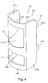
- FIG. 4 is a front perspective view of the guide member in accordance with the present invention.
- FIG. 5 is a back perspective view of the guide member in accordance with the present invention.
- FIG. 6 is a side elevational view of the guide member in accordance with the present invention.
- FIG. 7 is a perspective view of the limiter in accordance with the present invention.
- the bicycle 10 basically includes a frame body 12 which is bent into a V shape, and a front fork 13 . Furthermore, the bicycle 10 has a driving unit 15 swingably mounted on the lower part of the frame body 12 , a front wheel 16 f which is mounted on the lower end of the front fork 13 , a rear wheel 16 r which is mounted on the rear end of the driving unit 15 , and a handlebar part 17 which is connected to the upper part of the front fork 13 .
- the frame body 12 has a hollow frame main body 12 a , a head tube 12 b and a hanger part 12 c .
- the hollow frame main body 12 a is bent into a V shape.
- the head tube 12 b is disposed on the front part of the frame main body 12 a and supports the front fork 13 so that the front fork 13 is free to rotate about an inclined vertical axis.
- the hanger part 12 c is formed so that this hanger part 12 c extends downward from the bent part of the of the frame main body 12 a .
- the hanger part 12 c supports the driving unit 15 so that the driving unit is free to swing about the horizontal axis. As is shown in FIG.
- a slot-shaped first through-hole 12 d is formed in the rear surface of the head tube 12 b .
- the hole communicates with the frame main body 12 a and is extended in the circumferential direction so that no problems are created in the cable member even if the steerer tube 13 b is rotated approximately 160 degrees.
- two bearings 23 a and 23 b are used to rotatably support the steerer tube 13 b .
- the bearings 23 a and 23 b are mounted on the upper and lower ends of the head tube 12 b.
- the front fork 13 has a fork part 13 a with a front wheel 16 f mounted on the lower end thereof, and a steerer tube 13 b installed with an upright orientation on the upper end of the fork part 13 a .
- This steerer tube 13 b is rotatably mounted in the head tube 12 b .
- a second through-hole 13 c which communicates with the below-described handlebar stem 17 a is formed in the front surface at the upper end of the steerer tube 13 b
- a third through-hole 13 d which can communicate with the first through-hole 12 d is formed in the rear surface at the lower end.
- the third through-hole 13 d is a circular shape or rectangular shape opening so as to allow communication with the first through-hole 12 d .
- the third through-hole 13 d is an outer circumferential side opening of the steerer tube 13 b .
- the front fork 13 is rotatably mounted in the head tube 12 b in a state in which the ball race of the bearings 23 a and 23 b is adjusted by means of a conventionally configured mounting member 33 which is mounted on the upper part of the handlebar stem 17 a , and in which a nut part 33 a is engaged with the interior of the steerer tube 13 b.
- a crank unit 20 in which a pedal 22 is attached to the distal end thereof is mounted on the front end part of the driving unit 15 .
- An internal gearshift hub and an electrically driven gearshift unit which drives the internal gearshift hub are disposed inside the driving unit 15 .
- a power generating hub 21 into which a brake device 18 f having a roller brake configuration is incorporated is mounted on the front wheel 16 f
- a brake device 18 f having a roller brake configuration is mounted on the rear wheel 16 r.
- the handlebar part 17 has a handlebar stem 17 a which is fastened to the upper end part of the steerer tube 13 b of the front fork 13 , and a handlebar 17 b whose central part is fastened to the handlebar stem 17 a .
- the brake levers 19 f and 19 r are mounted on both ends of the handlebar 17 b for operating the front and rear brake devices 18 f and 18 r , respectively.
- a gearshift switch (not shown in the figures) used for the gearshift operation of the electrically driven gearshift unit is disposed on one end of the handlebar 17 b .
- the electrically driven gearshift unit is driven by power from the power generating hub.
- the handlebar stem 17 a has a slit 17 c and is fastened to the upper part of the steerer tube 13 b by narrowing this slit 17 c with the aid of two tightening bolts 32 . Furthermore, the front fork 13 is rotatably mounted in the head tube 12 b in a state in which the ball race of the bearings 23 a and 23 b is adjusted by means of a mounting member mounted on the upper part of the conventionally configured handlebar stem 17 a in which a nut part 33 a is engaged with the interior of the steerer tube 13 b.
- Bowden type front and rear brake cables 25 f and 25 r are threaded through as cable members that connect the front and rear brake devices 18 f and 18 r and the front and rear brake levers 19 f and 19 r , as is shown in FIGS. 2 and 3 . Furthermore, a first electrical wiring cord 27 is threaded through as a cable member that electrically connects the gearshift switch and the electrically operated gearshift unit, and a second electrical wiring cord 28 is threaded through as a cable member that connects the power generating hub 21 and the electrically operated gearshift unit.
- a cable installation aiding device 30 that is used to install and guide the rear cable member 25 r and first and second wiring cords 27 and 28 (among the cable members that are threaded through) to the steerer tube 13 b is attached inside the steerer tube 13 b .
- the brake cables 25 f and 25 r are hydraulic tubes and the front and rear brake devices 18 f and 18 r are hydraulic brake devices.
- the cable installation aiding device 30 has a guide member 40 that can be attached to the inner circumferential surface of the steerer tube 13 b , and a fork rotation limiter 41 that can be attached to the outer circumferential surface of the steerer tube 30 together with the guide member 40 , as shown in FIGS. 2 through 6 .
- the guide member 40 may, for example, be manufactured from a synthetic resin such as a polyacetal resin or the like.
- the guide member 40 guides the rear cable member 25 r and the first and second wiring cords 27 and 28 in order to facilitate the installation of these members as cable members.
- the guide member 40 has an attachment part 42 that is attached to the inner circumferential surface of the steerer tube 13 b , and first and second cable guide parts 43 and 44 that are disposed on the attachment part 42 .
- the attachment part 42 has two tubular screw fastening parts 42 a and 42 b disposed above and below with a gap in between, and a rib 42 c that connects and reinforces these fastening parts.
- attachment bolts 45 are threaded through the steerer tube 13 b and screwed into the respective screw fastening parts 42 a and 42 b so that the guide member 40 is fastened to the steerer tube 13 b together with the fork rotation limiter 41 .
- the attachment bolts 45 are preferably self-tapping screws.
- gaps 42 f are formed on both sides of the attachment part 42 in a state in which this part is mounted in the steerer tube 13 b , so that cable members such as the front brake cable 25 f , wiring cord that connects with the power generating hub, or the like can be threaded through.
- the distal ends of the screw fastening parts 42 a and 42 b are formed in a circular arcuate shape that conforms to the inner circumferential surface of the steerer tube 13 b .
- Screw attachment holes 42 d and 42 e are formed in the screw fastening parts 42 a and 42 b .
- attachment bolts 45 having the configuration of tapping screws are used, making it possible to dispense with the machining of the screw attachment holes 42 d and 42 e to form threads.
- the screw attachment holes 42 d and 42 e can be machined in advance to form threads.
- the first cable guide part 43 is formed in the upper part of the guide member 40 .
- the first cable guide part 43 is integrally formed with the attachment part 42 , and is a part that can guide the cable members (e.g., the rear brake cable 25 r and first wiring cord 27 ) disposed in the steerer tube ( 13 b ) on the side facing the handlebar stem ( 17 a ) (i.e., on the upper end in FIG. 2 ) and along the outer circumferential side of the steerer tube 13 b by changing the direction of these cable members to the outer circumferential side of the steerer tube 13 b .
- the cable members e.g., the rear brake cable 25 r and first wiring cord 27
- the first cable guide part 43 has a first guiding surface 43 a which is inclined and bent so as to connect the upper end and outer circumferential side of the steerer tube 13 b in a state in which the attachment part 42 is attached to the inner circumferential surface of the steerer tube 13 b .
- the first guiding part also has a pair of first side wall parts 43 b that are disposed on both sides of the first guiding surface 43 a , and a first connecting part 43 c that connects the first side wall parts 43 b . Cable members that are threaded through from the upper end or outer circumferential side can be guided to the outer circumferential side or upper end by means of this first guiding surface 43 .
- first guiding surface 43 a is bent in the forward-rearward direction (left-right direction in FIG. 6 ), and is also bent in the left-right direction (direction orthogonal to the plane of the page in FIG. 6 ). Accordingly, the distal end of the guided cable member tends to be deflected toward the central portion of the first guiding surface 43 a .
- one end of the first cable guide part 43 which includes the first connecting part 43 c , is formed in a circular arcuate shape having an external diameter that is slightly smaller than that of the inner circumferential surface of the steerer tube 13 b.
- the second cable guide part 44 is formed in the lower part of the guide member 40 with a vertical length that is less than that of the first cable guide part 43 .
- the second cable guide part 44 is integrally formed with the attachment part 42 , and is a part that can guide the cable members disposed (e.g., the second wiring cord 28 ) in the steerer tube ( 13 b ) on the side facing the fork part ( 13 a ) (i.e., on the lower end in FIG. 2 ) and along the outer circumferential side of the steerer tube 13 b by changing the direction of these cable members to the outer circumferential side of the steerer tube 13 b .
- the cable members disposed e.g., the second wiring cord 28
- the second cable guide part 44 has a second guiding surface 44 a which is inclined and bent so as to connect the lower end and outer circumferential side of the steerer tube 13 b in a state in which the attachment part 42 is attached to the inner circumferential surface of the steerer tube 13 b .
- the second cable guide part also has a pair of second side wall parts 44 b that are disposed on both sides of the second guiding surface 44 a , and a second connecting part 44 c that connects the second side wall parts 44 b . Cable members that are threaded through from the lower end or outer circumferential side can be guided to the outer circumferential side or lower end by means of this second guiding surface 44 .
- cable members can be led out in the desired direction merely by threading the cable members through toward the second guiding surface 44 a .
- the second guiding surface 44 a is bent in the forward-rearward direction (left-right direction in FIG. 6 ), and is also bent in the left-right direction (direction orthogonal to the plane of the page in FIG. 6 ). Accordingly, the distal end of the guided cable member tends to be deflected toward the central portion of the second guiding surface 44 a .
- the radius of curvature of this bent portion is greater than that of the first cable guide part 43 a .
- one end of the second cable guide part 44 which includes the second connecting part 44 c , has an external shape that is slightly less than the inner circumferential surface of the steerer tube 13 b .
- the guide member 40 as a whole thereby has an external shape that is slightly less than that of the steerer tube 13 b , so that the inner circumferential part of the steerer tube 13 b can be mounted with greater ease.
- the fork rotation limiter 41 is provided in order to prevent the occurrence of problems such as wire breakage or the like (due to rotation of the steerer tube 13 b ) in cable members mounted between the steerer tube 13 b and the frame main body 12 a .
- the fork rotation limiter 41 has a limiting member 46 which can be attached together with the attachment part 42 of the guide member 40 by means of two attachment bolts 45 , and a limiting projection 47 that comes into contact with the limiting member 46 .
- the limiting member 46 is a semicircular arcuate member fastened to the outer circumferential surface of the steerer tube 13 b by means of two attachment bolts 45 .
- the limiting member 46 In its outer circumferential surface, the limiting member 46 has a limiting groove 48 provided with first and second limiters 48 a and 48 b disposed at a specified circumferential interval (e.g., the center angle of the circular arc is approximately 160 degrees).
- the first and second limiters 48 a and 48 b are constructed by wall surfaces on both sides of the limiting groove 48 in the circumferential direction. Attachment holes 46 a and 46 b , through which the two attachment bolts 45 can be passed, are formed above and below at a specified interval in the central portion of the limiting member 46 in the circumferential direction on either side of the limiting groove 48 .
- the external shape of the limiting member 46 is smaller than the internal diameter of the lower bearing 23 b . Accordingly, the limiting member 46 can pass through the inner circumferential side of the bearing 23 b when mounted on the outer circumferential surface of the steerer tube 13 b .
- the steerer tube 13 b can be inserted from the lower end of the head tube 12 b and mounted in the head tube 12 b when the limiting member 46 and the guide member 40 are mounted in the steerer tube 30 beforehand by means of the same attachment bolts 45 .
- the limiting projection 47 is constructed from a bolt member. threadedly fastened to the head tube 12 b .
- the distal end of the limiting projection 47 is disposed between the first and second limiters 48 a and 48 b , and has a length that allows contact to be made with both limiters 48 a and 48 b .
- the limiting member 47 is not limited to a bolt member and may have any other construction as long this member has a configuration that can extend to the inner circumferential side of the head tube 12 b and contact both limiters 48 a ad 48 b.
- the mounting member 33 is removed, and the installation is performed in a state in which the interior of the steerer tube 13 b can easily be seen.
- the front brake cable 25 f is to be threaded through the frame main body 12 a from the interior of the steerer tube 13 b via the handlebar stem 17 a and second through-hole 13 c , the front brake cable 25 f that is led out from the handlebar stem 17 a is passed along of the two sides of the attachment part 42 of the guide member 40 and is conducted to a point beneath the steerer tube 13 b.
- the rear brake cable 25 r or first wiring cord 27 is to be threaded through the frame main body 12 a from the interior of the steerer tube 13 b via the handlebar stem 17 a , the rear brake cable 25 r or first wiring cord 27 that is led out from the handlebar stem 17 a is passed toward the first guiding surface 43 a of the first cable guide part 43 of the guide member 40 .
- the first wiring cord 27 When the distal end of the rear guide cable 25 r or the first wiring cord 27 comes into contact with the first guiding surface 43 a , the direction in which the cable member is threaded is changed to the outside circumferential surface by the first guiding surface 43 a , so that the rear brake cable 25 r or the first wiring cord 27 is led out into the interior of the frame main body 12 a via the third through-hole 13 d and first through-hole 12 d . In cases where the first wiring cord 27 does not have much elasticity, the first wiring cord 27 may be wrapped around the rear brake cable 25 r or the like, and the two cable members may be simultaneously installed.
- the second wiring cord 28 is to be threaded through the interior of the frame main body 12 a from the interior of the steerer tube 13 b via the fork part 13 a .
- the second wiring cord 28 is passed toward the second guiding surface 44 a of the second cable guide part 44 of the guide member 40 .
- the direction of passage of this cable member is changed to the outer circumferential side by the second guiding surface 44 a , so that the rear brake cable 25 r or the second wiring cord 28 is led out into the interior of the frame main body 12 a via the third through-hole 13 d and the first through-hole 12 d.
- the system is devised so that the guide member 40 of the cable installation aiding device 30 can be attached to the inner circumferential surface of the steerer tube 13 b , and that the direction of the cable member can be changed to the outer circumferential side of the steerer tube 13 b by the first cable guide part 43 . Therefore, the cable members can be guided to the outer circumferential side or upper end of the steerer tube in a simple manner merely by inserting the cable members from the upper end or outer circumferential side of the steerer tube. This can be achieved by machining the through-holes that communicate with the steerer tube 13 b or head tube 12 b . Accordingly, the exposure of the cable members can be minimized in the running of cable members to the outer circumferential side from the steerer tube.
- the first and second cable guide parts 43 and 44 were disposed on the upper part and lower part of the guide member 40 .
- both of these guide parts it would also be possible for both of these guide parts to be installed only on one or the other of these parts of the guide member 40 .
- cable members in the abovementioned embodiment were Bowden type brake cables 25 f and 25 r having inner cables and outer casings, and first and second electrical wiring cords 27 and 28 used for electrical wiring.
- the cable members that can be used are not limited to these.
- Bowden type gearshift cables, as well as hydraulic tubes used for hydraulic piping connected to disk brakes and the like can also be cited as examples of cable members that can be used.
- the guide member 40 and the limiting member 46 were attached by the same attachment bolts 45 . It is also possible, however, to mount the guide member and limiting member in the steerer tube separately. In this case, there are no restrictions on the mounting position of the limiting member.
- the term “configured” as used herein to describe a component, section or part of a device includes hardware and/or software that is constructed and/or programmed to carry out the desired function.
- the term “comprising” and its derivatives, as used herein are intended to be open ended terms that specify the presence of the stated features, elements, components, groups, integers, and/or steps, but do not exclude the presence of other unstated features, elements, components, groups, integers and/or steps.
- the foregoing also applies to words having similar meanings such as the terms, “including”, “having” and their derivatives.
- the terms “part,” “section,” “portion,” “member” or “element” when used in the singular can have the dual meaning of a single part or a plurality of parts.
- the following directional terms “forward, rearward, above, downward, vertical, horizontal, below and transverse” as well as any other similar directional terms refer to those directions of a bicycle equipped with the present invention. Accordingly, these terms, as utilized to describe the present invention should be interpreted relative to a bicycle equipped with the present invention as used in the normal riding position.
- terms of degree such as “substantially”, “about” and “approximately” as used herein mean a reasonable amount of deviation of the modified term such that the end result is not significantly changed. For example, these terms can be construed as including a deviation of at least ⁇ 5% of the modified term if this deviation would not negate the meaning of the word it modifies.
Abstract
Description
Claims (10)
Applications Claiming Priority (2)
| Application Number | Priority Date | Filing Date | Title |
|---|---|---|---|
| JP2005331630A JP4164087B2 (en) | 2005-11-16 | 2005-11-16 | Bicycle cable routing device |
| JP2005-331630 | 2005-11-16 |
Publications (2)
| Publication Number | Publication Date |
|---|---|
| US20070108723A1 US20070108723A1 (en) | 2007-05-17 |
| US7566065B2 true US7566065B2 (en) | 2009-07-28 |
Family
ID=37728212
Family Applications (1)
| Application Number | Title | Priority Date | Filing Date |
|---|---|---|---|
| US11/485,411 Expired - Fee Related US7566065B2 (en) | 2005-11-16 | 2006-07-13 | Bicycle cable installation aiding device |
Country Status (6)
| Country | Link |
|---|---|
| US (1) | US7566065B2 (en) |
| EP (1) | EP1787899B1 (en) |
| JP (1) | JP4164087B2 (en) |
| CN (1) | CN100522731C (en) |
| DE (1) | DE602006020673D1 (en) |
| TW (1) | TW200720132A (en) |
Cited By (19)
| Publication number | Priority date | Publication date | Assignee | Title |
|---|---|---|---|---|
| US20100051758A1 (en) * | 2008-08-29 | 2010-03-04 | Shimano Inc. | Bicycle wire holding arrangement |
| US20120175471A1 (en) * | 2011-01-11 | 2012-07-12 | Look Cycle International | Removable device for running a cable in a cycle frame |
| US20130154234A1 (en) * | 2010-08-12 | 2013-06-20 | Douglas Gregg Shadwell | Apparatus and Method for Routing Bicycle Control Cables |
| US8960702B2 (en) | 2011-09-22 | 2015-02-24 | Faraday Bicycles, Inc. | Electric bicycle |
| US9056646B1 (en) * | 2014-06-19 | 2015-06-16 | Specialized Bicycle Components, Inc. | Bicycle cable routing system |
| US9174695B1 (en) * | 2014-07-10 | 2015-11-03 | Neco Technology Industry Co., Ltd. | Head parts assembly for a bicycle with a cable collecting device |
| US9242692B2 (en) * | 2014-03-17 | 2016-01-26 | Shimano Inc. | Compression ring and head parts |
| US20170001677A1 (en) * | 2015-07-02 | 2017-01-05 | Canyon Bicycles Gmbh | Line Fixing Element for Lines Arranged in Bicycle Frame Tubes, Bicycle Frame Tubes, As Well As Method for Arranging and Fixing a Line in a Bicycle Frame Tube |
| US9656716B2 (en) * | 2015-03-13 | 2017-05-23 | Evan J. DeGray | Integrated cycling tool |
| US9840298B2 (en) | 2011-03-30 | 2017-12-12 | Specialized Bicycle Components, Inc. | Bicycle with bottom bracket cable guide |
| US20180215436A1 (en) * | 2015-04-14 | 2018-08-02 | Matthew Hendey | Apparatus, Systems, and Methods for Preventing Migration of Contaminants Within Tubing of a Frame |
| US20190077484A1 (en) * | 2015-05-21 | 2019-03-14 | Trek Bicycle Corporation | Rigid frame with high-compliance seat tube and internal cable routing |
| US10293879B1 (en) * | 2018-08-14 | 2019-05-21 | Pon Bicycle I B.V. | Bicycle handlebar assembly with v-shaped stem |
| US10399631B2 (en) | 2015-03-13 | 2019-09-03 | Evan J. DeGray | Integrated cycling tool |
| US20190367122A1 (en) * | 2018-05-31 | 2019-12-05 | Tien Hsin Industries Co., Ltd. | Cable routing system of bicycle |
| US11124259B2 (en) | 2018-08-21 | 2021-09-21 | Specialized Bicycle Components, Inc. | Bicycle with housing loop stay |
| US11292540B2 (en) * | 2019-03-16 | 2022-04-05 | X.L.T International Electronics Co., Ltd | Scooter |
| US11433968B2 (en) * | 2019-09-02 | 2022-09-06 | Koninklijke Gazelle N.V. | Bicycle |
| US11667348B2 (en) | 2018-08-21 | 2023-06-06 | Specialized Bicycle Components, Inc. | Bicycle with battery, motor and motor mount, wire routing, speed sensor, and dropper seat post |
Families Citing this family (26)
| Publication number | Priority date | Publication date | Assignee | Title |
|---|---|---|---|---|
| CN201086794Y (en) * | 2007-06-05 | 2008-07-16 | 深圳信隆实业股份有限公司 | Mounting structure of bicycle control cable |
| DE202007017669U1 (en) * | 2007-12-18 | 2009-04-30 | Rose Versand Gmbh | Bicycle frame with integrated trains |
| CN201195583Y (en) * | 2008-03-12 | 2009-02-18 | 深圳信隆实业股份有限公司 | Position limiter for control cable yarn of bicycle |
| DE102009012765A1 (en) * | 2009-03-12 | 2010-09-16 | Jochen Klieber | Frame element of a spring-loaded bicycle frame for guiding a pipe |
| NL2003770C2 (en) * | 2009-11-09 | 2011-05-11 | Batavus Bv | COUPLER AND METHOD FOR MANUFACTURING A BIKE FRAME. |
| CA2781239A1 (en) | 2011-07-04 | 2013-01-04 | Pon Bicycle Holding B.V. | Head tube assembly for a bicycle with cable access routing in an open steerer configuration |
| US20130175782A1 (en) * | 2011-07-05 | 2013-07-11 | Pon Bicycle Holding B.V. | Head tube assembly for a bicycle with an open steerer configuration |
| DE202011103814U1 (en) * | 2011-07-29 | 2012-11-15 | Canyon Bicycles Gmbh | Twin Bridges bicycle fork |
| JP6120312B2 (en) * | 2013-02-27 | 2017-04-26 | 本田技研工業株式会社 | Brake cable support structure for saddle-ride type vehicles |
| DE102013016536A1 (en) * | 2013-09-12 | 2015-03-12 | Merida & Centurion Germany Gmbh | Device for limiting the maximum steering angle on a bicycle |
| US9010789B1 (en) * | 2014-01-10 | 2015-04-21 | Neco Technology Industry Co., Ltd. | Head parts assembly for a bicycle |
| FR3020032B1 (en) * | 2014-04-18 | 2016-04-01 | Look Cycle Int | DEVICE FOR GUIDING A FLEXIBLE BONDING MEMBER THROUGH A CYCLE FRAME |
| CN103961229A (en) * | 2014-04-24 | 2014-08-06 | 李理 | Wheelchair brake cable guide device |
| EP3172120A1 (en) * | 2014-05-27 | 2017-05-31 | BMC Switzerland AG | Bicycle fork, bicycle frame and bicycle |
| DE102014110239A1 (en) * | 2014-07-21 | 2016-01-21 | Dr. Ing. H.C. F. Porsche Aktiengesellschaft | Longitudinal member of a motor vehicle and cable assembly for unlocking a front hood of a motor vehicle |
| US9580130B2 (en) * | 2015-02-26 | 2017-02-28 | Ford Global Technologies, Llc | Bicycle with detachable head-tube subassembly |
| TWI568622B (en) * | 2015-11-13 | 2017-02-01 | 溫芫鋐 | Cable arranging system for bicycle |
| DE102017211793A1 (en) | 2017-07-10 | 2019-01-10 | Gustav Magenwirth Gmbh & Co. Kg | Hydraulic line connection for a hydraulic brake handlebar guided vehicles, hydraulic line connection and hydraulic component fixing device for a hydraulic actuator handlebar guided vehicles, handlebar assembly for a handlebar-guided vehicle and hydraulic brake for a handlebar-guided vehicle |
| US10953948B2 (en) * | 2018-05-31 | 2021-03-23 | Tien Hsin Industries Co., Ltd. | Cable routing system of bicycle and stem thereof |
| IT201800011007A1 (en) * | 2018-12-12 | 2020-06-12 | Wilier Triestina S P A | STEERING LIMITER DEVICE FOR BICYCLES AND SIMILAR AND STEERING UNIT INCLUDING THIS DEVICE |
| TWI706884B (en) * | 2019-11-04 | 2020-10-11 | 銳聚動能股份有限公司 | Bicycle rack with charging hole |
| US11794848B2 (en) | 2020-12-14 | 2023-10-24 | Sram, Llc | Hydraulic brake control device with handlebar proximal hose attachment |
| US11912372B2 (en) | 2020-12-14 | 2024-02-27 | Sram, Llc | Hydraulic brake control device with handlebar proximal hose attachment |
| CN216468265U (en) * | 2021-08-18 | 2022-05-10 | 深圳酷骑童趣科技有限公司 | Bicycle handlebar upright structure and bicycle |
| DE202021106265U1 (en) * | 2021-11-17 | 2023-02-23 | Canyon Bicycles Gmbh | Steering stop for bicycle handlebars |
| DE202022103131U1 (en) * | 2022-06-02 | 2023-10-17 | Canyon Bicycles Gmbh | Steering system for bicycle handlebars |
Citations (8)
| Publication number | Priority date | Publication date | Assignee | Title |
|---|---|---|---|---|
| NL63610C (en) | 1900-01-01 | |||
| US4102219A (en) | 1977-08-19 | 1978-07-25 | Mtd Products Inc. | Fair-leads for a control wire |
| US4768798A (en) * | 1987-04-03 | 1988-09-06 | Reed Curtis H | Internal cable arrangement for bicycle frame |
| US6220398B1 (en) * | 1999-11-01 | 2001-04-24 | Wu Chin-Chang | Brake cable positioning assembly for an inner swivel connector of a free style bicycle |
| JP2005053363A (en) | 2003-08-05 | 2005-03-03 | Shimano Inc | Hollow structural component part bicycle |
| EP1598263A2 (en) | 2004-05-19 | 2005-11-23 | Shimano Inc. | Bicycle headset structure |
| US20060145446A1 (en) * | 2004-12-10 | 2006-07-06 | John Schmider | Method to conceal bicycle control cables within the handlebars, stem and frame |
| US7396032B2 (en) * | 2003-11-07 | 2008-07-08 | Shimano Inc. | Bicycle headset structure |
-
2005
- 2005-11-16 JP JP2005331630A patent/JP4164087B2/en not_active Expired - Fee Related
-
2006
- 2006-07-13 US US11/485,411 patent/US7566065B2/en not_active Expired - Fee Related
- 2006-08-04 TW TW095128701A patent/TW200720132A/en unknown
- 2006-09-08 DE DE602006020673T patent/DE602006020673D1/en active Active
- 2006-09-08 EP EP06018891A patent/EP1787899B1/en not_active Expired - Fee Related
- 2006-11-16 CN CNB2006101603406A patent/CN100522731C/en active Active
Patent Citations (9)
| Publication number | Priority date | Publication date | Assignee | Title |
|---|---|---|---|---|
| NL63610C (en) | 1900-01-01 | |||
| US4102219A (en) | 1977-08-19 | 1978-07-25 | Mtd Products Inc. | Fair-leads for a control wire |
| US4768798A (en) * | 1987-04-03 | 1988-09-06 | Reed Curtis H | Internal cable arrangement for bicycle frame |
| US6220398B1 (en) * | 1999-11-01 | 2001-04-24 | Wu Chin-Chang | Brake cable positioning assembly for an inner swivel connector of a free style bicycle |
| JP2005053363A (en) | 2003-08-05 | 2005-03-03 | Shimano Inc | Hollow structural component part bicycle |
| US7396032B2 (en) * | 2003-11-07 | 2008-07-08 | Shimano Inc. | Bicycle headset structure |
| EP1598263A2 (en) | 2004-05-19 | 2005-11-23 | Shimano Inc. | Bicycle headset structure |
| US6983949B2 (en) * | 2004-05-19 | 2006-01-10 | Shimano Inc. | Bicycle headset structure |
| US20060145446A1 (en) * | 2004-12-10 | 2006-07-06 | John Schmider | Method to conceal bicycle control cables within the handlebars, stem and frame |
Cited By (28)
| Publication number | Priority date | Publication date | Assignee | Title |
|---|---|---|---|---|
| US7854442B2 (en) * | 2008-08-29 | 2010-12-21 | Shimano Inc. | Bicycle wire holding arrangement |
| US20100051758A1 (en) * | 2008-08-29 | 2010-03-04 | Shimano Inc. | Bicycle wire holding arrangement |
| US20130154234A1 (en) * | 2010-08-12 | 2013-06-20 | Douglas Gregg Shadwell | Apparatus and Method for Routing Bicycle Control Cables |
| US9096287B2 (en) * | 2010-08-12 | 2015-08-04 | Douglas Gregg Shadwell | Apparatus and method for routing bicycle control cables |
| US20120175471A1 (en) * | 2011-01-11 | 2012-07-12 | Look Cycle International | Removable device for running a cable in a cycle frame |
| US9840298B2 (en) | 2011-03-30 | 2017-12-12 | Specialized Bicycle Components, Inc. | Bicycle with bottom bracket cable guide |
| US8960702B2 (en) | 2011-09-22 | 2015-02-24 | Faraday Bicycles, Inc. | Electric bicycle |
| US9242692B2 (en) * | 2014-03-17 | 2016-01-26 | Shimano Inc. | Compression ring and head parts |
| US9056646B1 (en) * | 2014-06-19 | 2015-06-16 | Specialized Bicycle Components, Inc. | Bicycle cable routing system |
| US9174695B1 (en) * | 2014-07-10 | 2015-11-03 | Neco Technology Industry Co., Ltd. | Head parts assembly for a bicycle with a cable collecting device |
| US9656716B2 (en) * | 2015-03-13 | 2017-05-23 | Evan J. DeGray | Integrated cycling tool |
| US10370055B2 (en) | 2015-03-13 | 2019-08-06 | Evan J. DeGray | Integrated cycling tool |
| US10399631B2 (en) | 2015-03-13 | 2019-09-03 | Evan J. DeGray | Integrated cycling tool |
| US20180215436A1 (en) * | 2015-04-14 | 2018-08-02 | Matthew Hendey | Apparatus, Systems, and Methods for Preventing Migration of Contaminants Within Tubing of a Frame |
| US10689056B2 (en) * | 2015-04-14 | 2020-06-23 | Matthew Hendey | Apparatus, systems, and methods for preventing migration of contaminants within tubing of a frame |
| US20190077484A1 (en) * | 2015-05-21 | 2019-03-14 | Trek Bicycle Corporation | Rigid frame with high-compliance seat tube and internal cable routing |
| US10710670B2 (en) * | 2015-05-21 | 2020-07-14 | Trek Bicycle Corporation | Rigid frame with high-compliance seat tube and internal cable routing |
| US10723407B2 (en) * | 2015-07-02 | 2020-07-28 | Canyon Bicycles Gmbh | Line fixing element for lines arranged in bicycle frame tubes, bicycle frame tubes, as well as method for arranging and fixing a line in a bicycle frame tube |
| US20170001677A1 (en) * | 2015-07-02 | 2017-01-05 | Canyon Bicycles Gmbh | Line Fixing Element for Lines Arranged in Bicycle Frame Tubes, Bicycle Frame Tubes, As Well As Method for Arranging and Fixing a Line in a Bicycle Frame Tube |
| US20190367122A1 (en) * | 2018-05-31 | 2019-12-05 | Tien Hsin Industries Co., Ltd. | Cable routing system of bicycle |
| US10293879B1 (en) * | 2018-08-14 | 2019-05-21 | Pon Bicycle I B.V. | Bicycle handlebar assembly with v-shaped stem |
| US10960951B2 (en) | 2018-08-14 | 2021-03-30 | Pon Bicycle I B. V. | Bicycle handlebar assembly with v-shaped stem |
| US20210214036A1 (en) * | 2018-08-14 | 2021-07-15 | Pon Bicycle I B. V. | Bicycle handlebar assembly with v-shaped stem |
| US11685462B2 (en) * | 2018-08-14 | 2023-06-27 | Pon Bicycle I B.V. | Bicycle handlebar assembly with v-shaped stem |
| US11124259B2 (en) | 2018-08-21 | 2021-09-21 | Specialized Bicycle Components, Inc. | Bicycle with housing loop stay |
| US11667348B2 (en) | 2018-08-21 | 2023-06-06 | Specialized Bicycle Components, Inc. | Bicycle with battery, motor and motor mount, wire routing, speed sensor, and dropper seat post |
| US11292540B2 (en) * | 2019-03-16 | 2022-04-05 | X.L.T International Electronics Co., Ltd | Scooter |
| US11433968B2 (en) * | 2019-09-02 | 2022-09-06 | Koninklijke Gazelle N.V. | Bicycle |
Also Published As
| Publication number | Publication date |
|---|---|
| EP1787899A1 (en) | 2007-05-23 |
| DE602006020673D1 (en) | 2011-04-28 |
| JP4164087B2 (en) | 2008-10-08 |
| US20070108723A1 (en) | 2007-05-17 |
| TW200720132A (en) | 2007-06-01 |
| EP1787899B1 (en) | 2011-03-16 |
| JP2007137173A (en) | 2007-06-07 |
| CN100522731C (en) | 2009-08-05 |
| CN1966341A (en) | 2007-05-23 |
Similar Documents
| Publication | Publication Date | Title |
|---|---|---|
| US7566065B2 (en) | Bicycle cable installation aiding device | |
| US8042427B2 (en) | Bicycle shifter | |
| US6983949B2 (en) | Bicycle headset structure | |
| US7396032B2 (en) | Bicycle headset structure | |
| US8201476B2 (en) | Bicycle operating device | |
| US9096287B2 (en) | Apparatus and method for routing bicycle control cables | |
| EP1715199A2 (en) | Cap member and bicycle cable system employing the cap member | |
| US20070191159A1 (en) | Bicycle derailleur | |
| US20060053954A1 (en) | Mountable bicycle structure | |
| US20070193387A1 (en) | Bicycle shift control device | |
| US7757581B2 (en) | Bicycle gear shifter | |
| WO2013041824A1 (en) | Bicycle | |
| US7121568B2 (en) | Motorcycle handlebar mounting system | |
| EP2543578A1 (en) | Head tube assembly for a bicycle with cable access routing in an open steerer configuration | |
| US7017929B2 (en) | Expandable bicycle headset structure | |
| US6862949B2 (en) | Conduit cover for bicycle | |
| US9821880B2 (en) | Bicycle rim brake |
Legal Events
| Date | Code | Title | Description |
|---|---|---|---|
| AS | Assignment |
Owner name: SHIMANO INC.,JAPAN Free format text: ASSIGNMENT OF ASSIGNORS INTEREST;ASSIGNOR:FUKUI, SEIJI;REEL/FRAME:018103/0161 Effective date: 20060712 Owner name: SHIMANO INC., JAPAN Free format text: ASSIGNMENT OF ASSIGNORS INTEREST;ASSIGNOR:FUKUI, SEIJI;REEL/FRAME:018103/0161 Effective date: 20060712 |
|
| FEPP | Fee payment procedure |
Free format text: PAYOR NUMBER ASSIGNED (ORIGINAL EVENT CODE: ASPN); ENTITY STATUS OF PATENT OWNER: LARGE ENTITY |
|
| STCF | Information on status: patent grant |
Free format text: PATENTED CASE |
|
| FPAY | Fee payment |
Year of fee payment: 4 |
|
| FPAY | Fee payment |
Year of fee payment: 8 |
|
| FEPP | Fee payment procedure |
Free format text: MAINTENANCE FEE REMINDER MAILED (ORIGINAL EVENT CODE: REM.); ENTITY STATUS OF PATENT OWNER: LARGE ENTITY |
|
| LAPS | Lapse for failure to pay maintenance fees |
Free format text: PATENT EXPIRED FOR FAILURE TO PAY MAINTENANCE FEES (ORIGINAL EVENT CODE: EXP.); ENTITY STATUS OF PATENT OWNER: LARGE ENTITY |
|
| STCH | Information on status: patent discontinuation |
Free format text: PATENT EXPIRED DUE TO NONPAYMENT OF MAINTENANCE FEES UNDER 37 CFR 1.362 |
|
| FP | Lapsed due to failure to pay maintenance fee |
Effective date: 20210728 |