US7572168B1 - Method and apparatus for high speed singulation - Google Patents
Method and apparatus for high speed singulation Download PDFInfo
- Publication number
- US7572168B1 US7572168B1 US11/717,912 US71791207A US7572168B1 US 7572168 B1 US7572168 B1 US 7572168B1 US 71791207 A US71791207 A US 71791207A US 7572168 B1 US7572168 B1 US 7572168B1
- Authority
- US
- United States
- Prior art keywords
- blade
- synthetic lubricant
- kerf
- application point
- speed
- Prior art date
- Legal status (The legal status is an assumption and is not a legal conclusion. Google has not performed a legal analysis and makes no representation as to the accuracy of the status listed.)
- Active, expires
Links
Images


Classifications
-
- B—PERFORMING OPERATIONS; TRANSPORTING
- B28—WORKING CEMENT, CLAY, OR STONE
- B28D—WORKING STONE OR STONE-LIKE MATERIALS
- B28D5/00—Fine working of gems, jewels, crystals, e.g. of semiconductor material; apparatus or devices therefor
- B28D5/02—Fine working of gems, jewels, crystals, e.g. of semiconductor material; apparatus or devices therefor by rotary tools, e.g. drills
- B28D5/022—Fine working of gems, jewels, crystals, e.g. of semiconductor material; apparatus or devices therefor by rotary tools, e.g. drills by cutting with discs or wheels
-
- B—PERFORMING OPERATIONS; TRANSPORTING
- B28—WORKING CEMENT, CLAY, OR STONE
- B28D—WORKING STONE OR STONE-LIKE MATERIALS
- B28D5/00—Fine working of gems, jewels, crystals, e.g. of semiconductor material; apparatus or devices therefor
- B28D5/0058—Accessories specially adapted for use with machines for fine working of gems, jewels, crystals, e.g. of semiconductor material
- B28D5/0076—Accessories specially adapted for use with machines for fine working of gems, jewels, crystals, e.g. of semiconductor material for removing dust, e.g. by spraying liquids; for lubricating, cooling or cleaning tool or work
-
- H—ELECTRICITY
- H01—ELECTRIC ELEMENTS
- H01L—SEMICONDUCTOR DEVICES NOT COVERED BY CLASS H10
- H01L24/00—Arrangements for connecting or disconnecting semiconductor or solid-state bodies; Methods or apparatus related thereto
- H01L24/93—Batch processes
- H01L24/95—Batch processes at chip-level, i.e. with connecting carried out on a plurality of singulated devices, i.e. on diced chips
- H01L24/97—Batch processes at chip-level, i.e. with connecting carried out on a plurality of singulated devices, i.e. on diced chips the devices being connected to a common substrate, e.g. interposer, said common substrate being separable into individual assemblies after connecting
-
- H—ELECTRICITY
- H01—ELECTRIC ELEMENTS
- H01L—SEMICONDUCTOR DEVICES NOT COVERED BY CLASS H10
- H01L2224/00—Indexing scheme for arrangements for connecting or disconnecting semiconductor or solid-state bodies and methods related thereto as covered by H01L24/00
- H01L2224/01—Means for bonding being attached to, or being formed on, the surface to be connected, e.g. chip-to-package, die-attach, "first-level" interconnects; Manufacturing methods related thereto
- H01L2224/42—Wire connectors; Manufacturing methods related thereto
- H01L2224/47—Structure, shape, material or disposition of the wire connectors after the connecting process
- H01L2224/48—Structure, shape, material or disposition of the wire connectors after the connecting process of an individual wire connector
- H01L2224/481—Disposition
- H01L2224/48151—Connecting between a semiconductor or solid-state body and an item not being a semiconductor or solid-state body, e.g. chip-to-substrate, chip-to-passive
- H01L2224/48221—Connecting between a semiconductor or solid-state body and an item not being a semiconductor or solid-state body, e.g. chip-to-substrate, chip-to-passive the body and the item being stacked
- H01L2224/48245—Connecting between a semiconductor or solid-state body and an item not being a semiconductor or solid-state body, e.g. chip-to-substrate, chip-to-passive the body and the item being stacked the item being metallic
- H01L2224/48247—Connecting between a semiconductor or solid-state body and an item not being a semiconductor or solid-state body, e.g. chip-to-substrate, chip-to-passive the body and the item being stacked the item being metallic connecting the wire to a bond pad of the item
-
- H—ELECTRICITY
- H01—ELECTRIC ELEMENTS
- H01L—SEMICONDUCTOR DEVICES NOT COVERED BY CLASS H10
- H01L2224/00—Indexing scheme for arrangements for connecting or disconnecting semiconductor or solid-state bodies and methods related thereto as covered by H01L24/00
- H01L2224/93—Batch processes
- H01L2224/95—Batch processes at chip-level, i.e. with connecting carried out on a plurality of singulated devices, i.e. on diced chips
- H01L2224/97—Batch processes at chip-level, i.e. with connecting carried out on a plurality of singulated devices, i.e. on diced chips the devices being connected to a common substrate, e.g. interposer, said common substrate being separable into individual assemblies after connecting
-
- H—ELECTRICITY
- H01—ELECTRIC ELEMENTS
- H01L—SEMICONDUCTOR DEVICES NOT COVERED BY CLASS H10
- H01L2924/00—Indexing scheme for arrangements or methods for connecting or disconnecting semiconductor or solid-state bodies as covered by H01L24/00
- H01L2924/10—Details of semiconductor or other solid state devices to be connected
- H01L2924/11—Device type
- H01L2924/14—Integrated circuits
Definitions
- the present invention is related to the field of semiconductor device manufacturing. More specifically, the present invention relates to high speed singulation for semiconductor devices.
- Singulation is a process for dicing a sheet of fabricated semiconductor die and/or packages into individual units. Semiconductor dice are typically mass produced on a wafer and good dice are mounted on a leadframe. The leadframes are also typically mass produced in large batches by the sheet.
- the sheet of leadframes can have an adhesive (dicing) tape applied to one side of the sheet before an encapsulation is applied to the dice mounted on the leadframes.
- the encapsulation is typically performed by molding a plastic resin to the sheet of dice and leadframes.
- the dicing tape provides a lower support structure for the formation of the plastic molding during encapsulation.
- the encapsulation is commonly referred to as a semiconductor package.
- a singulation process separates each package from the molded sheet.
- the molded sheet is typically divided into molded strips for singulation.
- One technique involves punching, while another technique involves sawing the molded strip to separate the packages from the molded strip.
- Two particular drawbacks related to sawing the molded strip are (1) lengthy singulation times and (2) defects in the singulated product. Both drawbacks are related to the heat generated by the singulation blade.
- the saw blade cuts the resin and can cut the lead frame into a plurality of particles. While cutting, the blade forms a well-known trench-like kerf.
- the kerf can fill with particles which can bind between the blade and a wall of the kerf. The particles can damage the wall of the kerf leading to failures or reliability problems.
- the singulation blade is generally operated at a rotational (spindle) speed of 20,000 rotations per minute (RPM), and a table speed of two inches per second (IPS). These speeds are typical of a conventional “Disco” type singulation machine.
- the table speed measures the (linear) speed of the blade moving along a molded strip during singulation of the molded strip, whereas the spindle speed approximates the rotational speed of the blade (about its axis), as the blade cuts through the molded strip.
- the relatively slow conventional speeds are used in the art to reduce blade overheating, to preserve blade life, and to reduce the number of defects in the singulated product.
- speeding up the singulation process is beneficial to improve throughput and thereby reduce costs associated with semiconductor manufacturing.
- increasing the rotational speed of the blade can promote faster singulation, there are significant tradeoffs in a conventional singulation process.
- Higher blade speeds increase blade temperature, which results in lower cutting efficiency, higher blade wear, and more singulation defects.
- DI deionized
- simple deionized water does not operate adequately to (1) cool the blade, (2) lubricate the blade, and (3) remove the buildup of particles on and around the blade and in the kerf during singulation, and particularly at higher RPM and/or lateral (IPS) blade movement.
- Simple deionized water has certain properties that inhibit proper service as a lubricant and coolant. One such property is the high surface tension of water, which causes the water to form high tension beads. The high tension beads do not distribute well over large surface areas, and do not penetrate into small spaces such as the kerf.
- the high tension beads do not adequately cool and lubricate high speed singulation blades, and do not properly remove the buildup of particles, which obstruct the blade during singulation. These obstructions lead to higher friction between the blade and the kerf, and the higher friction further causes high power consumption by the electric motor and other components of the blade. Thus, there is a need to accelerate the singulation process without negatively affecting the quality or reliability of the singulated product, or the longevity of useful blade life.
- Some embodiments of the invention disclose a method of singulation for a semiconductor device.
- the method applies a blade to a molded strip that includes the semiconductor device.
- the blade generates a kerf at a contact point between the blade and the molded strip.
- the kerf has a plurality of particles cut by the blade.
- the kerf separates the semiconductor dice from each other.
- the method cools the blade by using a synthetic lubricant.
- the method lubricates the blade by using the synthetic lubricant or a combination of DI water and the synthetic lubricant.
- synthetic lubricant is meant to include the synthetic lubricant (and/or coolant) and a combination thereof with water.
- the method rinses the kerf by using the synthetic lubricant. Rinsing the kerf removes a substantial quantity of the particles from the kerf.
- the blade moves at a high rate of speed, such as, for instance, at a spindle speed of approximately 30,000 to 50,000 rotations per minute, and/or at a table speed of approximately 4-10 inches per minute.
- a high rate of speed such as, for instance, at a spindle speed of approximately 30,000 to 50,000 rotations per minute, and/or at a table speed of approximately 4-10 inches per minute.
- the method substantially reduces the coefficient of friction between the blade and the kerf.
- the method typically cools the blade by directing the synthetic lubricant toward the blade, such that the temperature of the blade is substantially reduced.
- the power consumed from the blade's operation is substantially reduced, such as, for instance, from 3.5 Amps to about 1.9 Amps, in some embodiments.
- Rinsing the kerf typically comprises injecting the synthetic lubricant into the kerf.
- the semiconductor device includes a die and/or leadframe.
- the molded strip of various embodiments includes a plurality of semiconductor packages. Often, the molded strip further has a dicing tape attached to a side of the molded strip.
- Some embodiments of the invention provide a system for singulation of a semiconductor device.
- the system comprises a molded strip, a blade, a temperature control device, and a synthetic lubricant.
- the molded strip has a plurality of semiconductor devices.
- the blade is for singulating the semiconductor device from the molded strip. When the blade contacts the molded strip, the blade generates a kerf.
- the kerf has a plurality of particles.
- the temperature control device is configured to apply the synthetic lubricant to the blade.
- the synthetic lubricant cools the blade and lubricates the blade during a singulation process.
- the temperature control device of some embodiments further comprises a nozzle for directing the synthetic lubricant toward the blade.
- the nozzle of some embodiments injects the synthetic lubricant into the kerf. In these cases, the synthetic lubricant typically enters the kerf and substantially removes the particles from the kerf.
- Some systems further include a dicing tape.
- the semiconductor devices of these systems are typically attached to the dicing tape.
- the semiconductor device of some embodiments comprises a die and/or leadframe and the molded strip often has one or more semiconductor packages thereon. These semiconductor packages typically include a leadframe, a semiconductor die coupled to the lead frame, and a capsule enclosing the semiconductor die.
- the leadframe of some embodiments comprises an alloy.
- FIG. 1 is an illustration of an apparatus for semiconductor device singulation.
- FIG. 2 illustrates a singulation process
- FIG. 3 illustrates a burr caused by a singulation process.
- FIG. 4 illustrates a smear caused by a singulation process.
- FIG. 5 shows a solder melt caused by a singulation process.
- FIG. 6 illustrates cooling a singulation blade with deionized water.
- FIG. 7 illustrates a singulation blade generating a kerf in a molded strip in accordance with some embodiments of the invention.
- FIG. 8 illustrates cooling and lubricating a singulation blade, and rinsing a kerf, with a synthetic lubricant according to some embodiments of the invention.
- FIG. 9 compares the surface tension of deionized water with the surface tension of a synthetic lubricant.
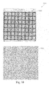
- FIG. 10 presents the results of a delamination test immediately after singulation.
- FIG. 11 presents the results of a delamination test after a brief exposure to stress conditions at high heat.
- FIG. 12 illustrates a high speed singulation process according to some embodiments of the invention.
- FIG. 1 is an illustration of a system for semiconductor device singulation.
- the system 100 includes a singulation blade 105 , a molded strip 110 , a dicing tape 115 , and a kerf 120 .
- the molded strip 110 typically includes a number of semiconductor devices that are fabricated on sheets comprising various combinations of metal, semiconductor, and molding material. The sheets of different fabrication processes and with different die have various sizes and shapes before the sheets are diced by a singulation process to yield the individual semiconductor devices.
- the dicing tape 115 is typically an adhesive (dicing) tape that is used in the fabrication process.
- the blade 105 is applied to the molded strip 110 .
- the blade 105 When applied to the molded strip, the blade 105 typically cuts into or through the molded strip 110 , which generates the kerf 120 .
- the kerf 120 has substantially parallel walls cut into the molded strip, spaced apart from each other approximately the thickness of the blade.
- the blade 105 rotates at a high rate of speed.
- the spindle speed of the blade 105 is approximately 30,000 to 50,000 rotations per minute (RPM), while in some embodiments the table speed is approximately 4-10 inches per second (IPS).
- RPM rotations per minute
- IPS inches per second
- generation of the kerf 120 produces a large amount of loose sawed particles, which, without the invention, would come to rest within the kerf 120 .
- the particles within the kerf 120 can increase the coefficient of friction of the blade 105 against the walls of the kerf 120 , and increase the power consumed to operate the blade 105 , while lowering the rate of cutting through the molded strip 110 and the dicing tape 115 .
- particles can get caught and bind between the blade 105 and the walls of the kerf 120 .
- the increased friction on the blade 105 and the longer cutting time further increase the temperature of the blade 105 , and thus exasperate the problems caused by an overheated blade: (1) premature blade wear and (2) defects in the singulated product.
- FIG. 2 illustrates a closer view of the system 200 during a singulation process.
- the blade 205 of some embodiments is comprised of several grits 206 secured by a resin 207 .
- the grits 206 are typically formed out of diamond or another suitable substance.
- a number of loose sawed particles 225 undesirably accumulate in the kerf 220 , which undesirably degrades the cutting efficiency of the blade 205 .
- the application of the blade 205 in the kerf 220 typically generates an undesirable amount of heat that can cause several types of defects in the singulated product.
- FIGS. 3 , 4 and 5 illustrate examples of some of these defects.
- FIG. 3 illustrates a burr caused by a singulation process.
- a lead frame 300 has several leads 305 .
- the lead frame 300 has undergone a singulation process in which undesirable particles in the kerf and an overheated blade has caused the burrs 310 and 315 in the leads 305 on a side of the leadframe 300 .
- the burrs are caused in one or more directions, for example, the X-direction 310 and/or the Y-direction 315 .
- a Z-direction burr 420 is illustrated in FIG. 4 .
- FIG. 4 presents a side view of the leads 305 of the lead frame 300 .
- FIG. 4 also illustrates a smear 425 between the leads 305 of the leadframe 300 caused by a singulation process. As shown in this figure, the smear 425 brings the leads 305 of the leadframe 300 undesirably near each other.
- FIG. 5 shows a solder melt caused by a singulation process.
- the lead 505 of a leadframe has an undesirable solder melt 550 that has oozed beyond the boundary of the lead 505 .
- the solder melt 550 is often caused by an overheated blade.
- FIG. 6 illustrates a system 600 , which attempts to cool a singulation blade 605 with deionized water 630 .
- deionized water does not operate adequately to (1) cool the blade 605 , particularly at higher spindle and/or table speeds, (2) lubricate the blade 605 , and (3) remove the buildup of particles 625 from the kerf 620 .
- FIG. 7 illustrates a system 700 for cooling and lubricating a singulation blade 705 , and rinsing a kerf 720 , with a temperature control device 730 and a synthetic lubricant according to some embodiments of the invention.
- the temperature control device 730 is coupled to a chiller module 745 , which is coupled to a reservoir 740 .
- the reservoir 740 typically stores a fluid, such as, for example, the synthetic lubricant, distilled water, and/or a combination thereof.
- the chiller module 745 receives the synthetic lubricant or other fluid from the reservoir 740 , and chills or cools it. Some embodiments cool the synthetic lubricant to a temperature of approximately 20 degrees Celsius.
- the chiller module 745 cools the synthetic lubricant
- the blade 705 typically generates a kerf 720 in a molded strip. While the kerf 720 is generated, the temperature control device 730 directs the cooled synthetic lubricant in particular ways.
- FIG. 8 illustrates a top view of the operation of the temperature control device 730 , according to some embodiments.
- the temperature control device 730 of these embodiments applies a synthetic lubricant 735 towards several locations of the blade 705 , as well as directly at the cutting locus of the blade 705 . Further the temperature control device 730 injects the synthetic lubricant 735 directly into the kerf 720 .
- the temperature control device 730 employs one or more nozzles for directing the synthetic lubricant 735 . The application method of these embodiments, achieves superior results over the art.
- FIG. 9 compares the surface tension of deionized water with the surface tension of a synthetic lubricant. As shown in this figure, the deionized water tends to form a high tension bead 910 on a surface of the blade 705 .
- the high tension bead 910 forms a large bead angle (alpha), which prevents the deionized water from distributing over a greater surface of the blade 705 .
- the high tension bead 910 has a high profile with respect to the surface of the blade 705 and, thus, does not penetrate between the blade 705 and the loose particles in the kerf.
- the synthetic lubricant 915 has a lower surface tension than the deionized water and the synthetic lubricant 915 is distributed at a lower angle (beta) over a broader surface of the blade 705 .
- the synthetic lubricant covers a greater surface area and enters tighter regions formed between the blade and the loose particles within the kerf.
- FIG. 10 presents the results 1000 of a delamination test immediately after singulation.
- the results 1000 presented in this figure compare a high speed singulation process 1010 versus a conventional singulation process 1005 .
- the products of the high speed singulation process 1010 exhibit no incidences of singulation defects over the conventional lower speed process 1005 .
- the high speed singulation process 1010 is performed at a blade spindle rotation rate of approximately 30,000 to 50,000 RPM and/or a table speed of approximately 4 to 10 IPS.
- the blade of the embodiments described above draws current of about 1.9 Amps.
- the conventional singulation process draws about 3.5 Amps, while cutting laterally through the molded strip at only about 2.0 IPS, and at a spindle speed of only 20,000 RPM.
- FIG. 11 presents the results 1100 of a delamination test after a brief exposure to high heat stress conditions.
- the heat stress conditions were applied after singulation by autoclaving at 260° C., 15 psi, 100% relative humidity, then infrared and/or conventional (wire) heating reflow, three times.
- These results 1100 compare a high speed singulation process 1110 versus a conventional singulation process 1105 .
- the high speed singulation process 1110 exhibited no incidences of singulation defects over the conventional singulation process 1105 , despite operating at a higher speed.
- FIG. 12 summarizes the high speed singulation process 1200 of some embodiments of the invention.
- the process 1200 begins at the step 1205 , where the blade rotates at a high RPM.
- the blade of some embodiments rotates at a spindle speed of approximately 30,000 to 50,000 RPM, and/or cuts at table speed of 4-10 IPS.
- the blade is applied to a molded strip that has one or more semiconductor devices on the molded strip.
- the synthetic lubricant is directed toward the blade. The synthetic lubricant will tend to cool the blade.
- the synthetic fluid is directed toward the cutting locus of the blade to lubricate the blade.
- the improved blade lubrication lowers the coefficient of friction between the blade and the cutting locus, which further lowers the temperature of the blade, and/or power consumption.
- the overall power consumption is from 3.5 Amps to about 1.9 Amps.
- some embodiments inject the synthetic lubricant directly into the kerf. This tends to loosen the sawed particles in the kerf.
- the synthetic lubricant further acts to rinse the kerf of the particles. Then, the process 1200 concludes.
- some embodiments of the invention provide a method and system for using a synthetic lubricant in a singulation process.
- the combination of an appropriate synthetic lubricant and an effective cooling device, together with a process for applying the device and lubricant, overcomes the drawbacks of high temperature and blade wear rate.
- the cooler running blade reduces metal fatigue and extends the effective cutting efficiency and useful life of the blade.
- the cooler running blade typically operates at higher rotations per minute (RPM) and/or inches per second (IPS), in terms of spindle and/or table speeds, which results in faster and more efficient singulation for semiconductor fabrication. The result is a higher throughput than the conventional singulation process without a tradeoff in the quality of the singulated product.
Abstract
Description
Claims (37)
Priority Applications (1)
| Application Number | Priority Date | Filing Date | Title |
|---|---|---|---|
| US11/717,912 US7572168B1 (en) | 2006-04-13 | 2007-03-13 | Method and apparatus for high speed singulation |
Applications Claiming Priority (2)
| Application Number | Priority Date | Filing Date | Title |
|---|---|---|---|
| US79209306P | 2006-04-13 | 2006-04-13 | |
| US11/717,912 US7572168B1 (en) | 2006-04-13 | 2007-03-13 | Method and apparatus for high speed singulation |
Publications (1)
| Publication Number | Publication Date |
|---|---|
| US7572168B1 true US7572168B1 (en) | 2009-08-11 |
Family
ID=40934260
Family Applications (1)
| Application Number | Title | Priority Date | Filing Date |
|---|---|---|---|
| US11/717,912 Active 2027-07-24 US7572168B1 (en) | 2006-04-13 | 2007-03-13 | Method and apparatus for high speed singulation |
Country Status (1)
| Country | Link |
|---|---|
| US (1) | US7572168B1 (en) |
Cited By (4)
| Publication number | Priority date | Publication date | Assignee | Title |
|---|---|---|---|---|
| US20120137847A1 (en) * | 2010-12-02 | 2012-06-07 | Disco Corporation | Cutting apparatus |
| RU2464166C1 (en) * | 2011-02-25 | 2012-10-20 | Федеральное государственное бюджетное образовательное учреждение высшего профессионального образования "Ульяновский государственный технический университет" | Method of sawing hard stone rock |
| US20160311127A1 (en) * | 2015-04-24 | 2016-10-27 | Disco Corporation | Cutting apparatus and cutting method |
| RU2689938C1 (en) * | 2018-09-27 | 2019-05-29 | Леонид Иванович Шабалин | Method of accelerated stone cutting and semi-automatic stone cutting machine for its implementation |
Citations (16)
| Publication number | Priority date | Publication date | Assignee | Title |
|---|---|---|---|---|
| US3169923A (en) * | 1962-03-22 | 1965-02-16 | Universal Oil Prod Co | Oil of lubricating viscosity |
| US3203895A (en) * | 1962-03-22 | 1965-08-31 | Universal Oil Prod Co | Lubricating oils containing amine salts of phosphates |
| US3611061A (en) | 1971-07-07 | 1971-10-05 | Motorola Inc | Multiple lead integrated circuit device and frame member for the fabrication thereof |
| US4801561A (en) | 1984-07-05 | 1989-01-31 | National Semiconductor Corporation | Method for making a pre-testable semiconductor die package |
| US5372220A (en) * | 1992-06-01 | 1994-12-13 | Bostik, Inc. | Water based lubricant containing polytetrafluoroethylene |
| US5396185A (en) | 1990-08-13 | 1995-03-07 | Kabushiki Kaisha Toshiba | System and carrier for testing semiconductor integrated circuit devices |
| US5832585A (en) * | 1996-08-13 | 1998-11-10 | National Semiconductor Corporation | Method of separating micro-devices formed on a substrate |
| US5923995A (en) * | 1997-04-18 | 1999-07-13 | National Semiconductor Corporation | Methods and apparatuses for singulation of microelectromechanical systems |
| US6304000B1 (en) | 1997-04-30 | 2001-10-16 | Dow Corning Toray Silicone Company, Ltd. | Semiconductor device comprising silicone adhesive sheet |
| US6386948B1 (en) * | 1999-06-01 | 2002-05-14 | Sumitomo Special Metals Co., Ltd. | Magnet member cutting method and magnet member cutting |
| US6428883B1 (en) * | 1999-05-13 | 2002-08-06 | Xerox Corporation | Resinoid dicing blade including a dry lubricant |
| US6521513B1 (en) * | 2000-07-05 | 2003-02-18 | Eastman Kodak Company | Silicon wafer configuration and method for forming same |
| US20050056135A1 (en) * | 2003-09-16 | 2005-03-17 | Kenneth Hall | Multi-chip facet cutting saw blade and related method |
| US6902469B2 (en) * | 1999-12-28 | 2005-06-07 | Neomax Co., Ltd. | Work chamfering apparatus and work chamfering method |
| US20050268899A1 (en) * | 2004-02-23 | 2005-12-08 | Towa Intercon Technology, Inc. | Saw singulation |
| US7008825B1 (en) | 2003-05-27 | 2006-03-07 | Amkor Technology, Inc. | Leadframe strip having enhanced testability |
-
2007
- 2007-03-13 US US11/717,912 patent/US7572168B1/en active Active
Patent Citations (18)
| Publication number | Priority date | Publication date | Assignee | Title |
|---|---|---|---|---|
| US3169923A (en) * | 1962-03-22 | 1965-02-16 | Universal Oil Prod Co | Oil of lubricating viscosity |
| US3203895A (en) * | 1962-03-22 | 1965-08-31 | Universal Oil Prod Co | Lubricating oils containing amine salts of phosphates |
| US3611061A (en) | 1971-07-07 | 1971-10-05 | Motorola Inc | Multiple lead integrated circuit device and frame member for the fabrication thereof |
| US4801561A (en) | 1984-07-05 | 1989-01-31 | National Semiconductor Corporation | Method for making a pre-testable semiconductor die package |
| US5396185A (en) | 1990-08-13 | 1995-03-07 | Kabushiki Kaisha Toshiba | System and carrier for testing semiconductor integrated circuit devices |
| US5372220A (en) * | 1992-06-01 | 1994-12-13 | Bostik, Inc. | Water based lubricant containing polytetrafluoroethylene |
| US5832585A (en) * | 1996-08-13 | 1998-11-10 | National Semiconductor Corporation | Method of separating micro-devices formed on a substrate |
| US5923995A (en) * | 1997-04-18 | 1999-07-13 | National Semiconductor Corporation | Methods and apparatuses for singulation of microelectromechanical systems |
| US6304000B1 (en) | 1997-04-30 | 2001-10-16 | Dow Corning Toray Silicone Company, Ltd. | Semiconductor device comprising silicone adhesive sheet |
| US6428883B1 (en) * | 1999-05-13 | 2002-08-06 | Xerox Corporation | Resinoid dicing blade including a dry lubricant |
| US6386948B1 (en) * | 1999-06-01 | 2002-05-14 | Sumitomo Special Metals Co., Ltd. | Magnet member cutting method and magnet member cutting |
| US6902469B2 (en) * | 1999-12-28 | 2005-06-07 | Neomax Co., Ltd. | Work chamfering apparatus and work chamfering method |
| US6521513B1 (en) * | 2000-07-05 | 2003-02-18 | Eastman Kodak Company | Silicon wafer configuration and method for forming same |
| US7008825B1 (en) | 2003-05-27 | 2006-03-07 | Amkor Technology, Inc. | Leadframe strip having enhanced testability |
| US20050056135A1 (en) * | 2003-09-16 | 2005-03-17 | Kenneth Hall | Multi-chip facet cutting saw blade and related method |
| US20050268899A1 (en) * | 2004-02-23 | 2005-12-08 | Towa Intercon Technology, Inc. | Saw singulation |
| US20070175304A1 (en) * | 2004-02-23 | 2007-08-02 | Koninklijke Philips Electronics, N.V. | Nozzle assembly for a saw for semiconductors |
| US7281535B2 (en) * | 2004-02-23 | 2007-10-16 | Towa Intercon Technology, Inc. | Saw singulation |
Cited By (6)
| Publication number | Priority date | Publication date | Assignee | Title |
|---|---|---|---|---|
| US20120137847A1 (en) * | 2010-12-02 | 2012-06-07 | Disco Corporation | Cutting apparatus |
| CN102528952A (en) * | 2010-12-02 | 2012-07-04 | 株式会社迪思科 | Cutting apparatus |
| CN102528952B (en) * | 2010-12-02 | 2016-02-10 | 株式会社迪思科 | Topping machanism |
| RU2464166C1 (en) * | 2011-02-25 | 2012-10-20 | Федеральное государственное бюджетное образовательное учреждение высшего профессионального образования "Ульяновский государственный технический университет" | Method of sawing hard stone rock |
| US20160311127A1 (en) * | 2015-04-24 | 2016-10-27 | Disco Corporation | Cutting apparatus and cutting method |
| RU2689938C1 (en) * | 2018-09-27 | 2019-05-29 | Леонид Иванович Шабалин | Method of accelerated stone cutting and semi-automatic stone cutting machine for its implementation |
Similar Documents
| Publication | Publication Date | Title |
|---|---|---|
| US10395967B2 (en) | Method for manufacturing semiconductor device | |
| US9034731B2 (en) | Integrated, integrated circuit singulation system | |
| US7572168B1 (en) | Method and apparatus for high speed singulation | |
| JP4885553B2 (en) | Dicing method and dicing apparatus | |
| TWI443004B (en) | Method for cooling a workpiece made of a semiconductor material during an online sawing process | |
| US8449356B1 (en) | High pressure cooling nozzle for semiconductor package | |
| US11107915B2 (en) | Semiconductor device | |
| JP2007194469A (en) | Method for manufacturing semiconductor device | |
| US7086394B2 (en) | Grindable self-cleaning singulation saw blade and method | |
| TWI310960B (en) | Method and apparatus for manufacturing a packaged semiconductor device, packaged semiconductor device obtained with such a method and metal carrier suitable for use in such a method | |
| Anuar et al. | Saw singulation characterization on high profile multi chip module packages with thick leadframe | |
| KR101897082B1 (en) | Apparatus of ingot slicing and method of ingot slicing | |
| Paydenkar et al. | Wafer sawing process characterization for thin die (75micron) applications | |
| WO2006041411A1 (en) | Cooling and lubrication system | |
| US20040043536A1 (en) | Method of producing integrated circuit package units | |
| JP3443799B2 (en) | Method and apparatus for cutting out semiconductor device | |
| KR100953078B1 (en) | Wafer sawing equipment improving a cooling function | |
| US20240091968A1 (en) | Blade for sawing a panel level package and method of sawing a panel level package using the same | |
| Vigneswaran et al. | Lead delamination correlation with Sn layer melting during sawing in power QFN package | |
| US20020048850A1 (en) | Method for sawing a moulded leadframe package | |
| Yu et al. | Optimization of Saw Street Configuration to Save Saw Blade in Assembling QFN Packages | |
| KR0127356Y1 (en) | Saw blade for wafer cutting | |
| US20090127684A1 (en) | Leadframe for leadless package | |
| KR0156472B1 (en) | Dambar cutting of leadframe and the structure | |
| JP6091959B2 (en) | Wafer cutting apparatus and wafer cutting method |
Legal Events
| Date | Code | Title | Description |
|---|---|---|---|
| AS | Assignment |
Owner name: UTAC THAI LIMITED, THAILAND Free format text: ASSIGNMENT OF ASSIGNORS INTEREST;ASSIGNORS:PHAOWONGSA, APICHART;NONDHASITTHICHAI, SOMCHAI;SAE-LEE, CHARUN;AND OTHERS;REEL/FRAME:019089/0678;SIGNING DATES FROM 20070312 TO 20070313 |
|
| STCF | Information on status: patent grant |
Free format text: PATENTED CASE |
|
| FEPP | Fee payment procedure |
Free format text: PAYOR NUMBER ASSIGNED (ORIGINAL EVENT CODE: ASPN); ENTITY STATUS OF PATENT OWNER: LARGE ENTITY |
|
| FPAY | Fee payment |
Year of fee payment: 4 |
|
| AS | Assignment |
Owner name: UTAC HEADQUARTERS PTE. LTD., SINGAPORE Free format text: ASSIGNMENT OF ASSIGNORS INTEREST;ASSIGNOR:UTAC THAI LIMITED;REEL/FRAME:037959/0937 Effective date: 20150508 |
|
| AS | Assignment |
Owner name: UTAC HEADQUARTERS PTE. LTD., SINGAPORE Free format text: CORRECTIVE ASSIGNMENT TO ADD THE ANNEX A AND THE ANNEX B WHICH WAS INADVERTENTLY LEFTOUT IN THE ORIGINAL ASSIGNMENT DOCUMENT PREVIOUSLY RECORDED ON REEL 037959 FRAME 0937. ASSIGNOR(S) HEREBY CONFIRMS THE ASSIGNMENT;ASSIGNOR:UTAC THAI LIMITED;REEL/FRAME:039902/0302 Effective date: 20150508 |
|
| FPAY | Fee payment |
Year of fee payment: 8 |
|
| MAFP | Maintenance fee payment |
Free format text: PAYMENT OF MAINTENANCE FEE, 12TH YEAR, LARGE ENTITY (ORIGINAL EVENT CODE: M1553); ENTITY STATUS OF PATENT OWNER: LARGE ENTITY Year of fee payment: 12 |