US7572408B2 - Ductile cobalt-based Laves phase alloys - Google Patents
Ductile cobalt-based Laves phase alloys Download PDFInfo
- Publication number
- US7572408B2 US7572408B2 US11/015,129 US1512904A US7572408B2 US 7572408 B2 US7572408 B2 US 7572408B2 US 1512904 A US1512904 A US 1512904A US 7572408 B2 US7572408 B2 US 7572408B2
- Authority
- US
- United States
- Prior art keywords
- metallic composition
- alloy
- based metallic
- composition
- ratio
- Prior art date
- Legal status (The legal status is an assumption and is not a legal conclusion. Google has not performed a legal analysis and makes no representation as to the accuracy of the status listed.)
- Active
Links
Images


Classifications
-
- C—CHEMISTRY; METALLURGY
- C22—METALLURGY; FERROUS OR NON-FERROUS ALLOYS; TREATMENT OF ALLOYS OR NON-FERROUS METALS
- C22C—ALLOYS
- C22C19/00—Alloys based on nickel or cobalt
- C22C19/07—Alloys based on nickel or cobalt based on cobalt
-
- B—PERFORMING OPERATIONS; TRANSPORTING
- B22—CASTING; POWDER METALLURGY
- B22F—WORKING METALLIC POWDER; MANUFACTURE OF ARTICLES FROM METALLIC POWDER; MAKING METALLIC POWDER; APPARATUS OR DEVICES SPECIALLY ADAPTED FOR METALLIC POWDER
- B22F3/00—Manufacture of workpieces or articles from metallic powder characterised by the manner of compacting or sintering; Apparatus specially adapted therefor ; Presses and furnaces
- B22F3/115—Manufacture of workpieces or articles from metallic powder characterised by the manner of compacting or sintering; Apparatus specially adapted therefor ; Presses and furnaces by spraying molten metal, i.e. spray sintering, spray casting
-
- B—PERFORMING OPERATIONS; TRANSPORTING
- B22—CASTING; POWDER METALLURGY
- B22F—WORKING METALLIC POWDER; MANUFACTURE OF ARTICLES FROM METALLIC POWDER; MAKING METALLIC POWDER; APPARATUS OR DEVICES SPECIALLY ADAPTED FOR METALLIC POWDER
- B22F7/00—Manufacture of composite layers, workpieces, or articles, comprising metallic powder, by sintering the powder, with or without compacting wherein at least one part is obtained by sintering or compression
- B22F7/02—Manufacture of composite layers, workpieces, or articles, comprising metallic powder, by sintering the powder, with or without compacting wherein at least one part is obtained by sintering or compression of composite layers
- B22F7/04—Manufacture of composite layers, workpieces, or articles, comprising metallic powder, by sintering the powder, with or without compacting wherein at least one part is obtained by sintering or compression of composite layers with one or more layers not made from powder, e.g. made from solid metal
-
- B—PERFORMING OPERATIONS; TRANSPORTING
- B22—CASTING; POWDER METALLURGY
- B22F—WORKING METALLIC POWDER; MANUFACTURE OF ARTICLES FROM METALLIC POWDER; MAKING METALLIC POWDER; APPARATUS OR DEVICES SPECIALLY ADAPTED FOR METALLIC POWDER
- B22F7/00—Manufacture of composite layers, workpieces, or articles, comprising metallic powder, by sintering the powder, with or without compacting wherein at least one part is obtained by sintering or compression
- B22F7/06—Manufacture of composite layers, workpieces, or articles, comprising metallic powder, by sintering the powder, with or without compacting wherein at least one part is obtained by sintering or compression of composite workpieces or articles from parts, e.g. to form tipped tools
- B22F7/08—Manufacture of composite layers, workpieces, or articles, comprising metallic powder, by sintering the powder, with or without compacting wherein at least one part is obtained by sintering or compression of composite workpieces or articles from parts, e.g. to form tipped tools with one or more parts not made from powder
-
- C—CHEMISTRY; METALLURGY
- C23—COATING METALLIC MATERIAL; COATING MATERIAL WITH METALLIC MATERIAL; CHEMICAL SURFACE TREATMENT; DIFFUSION TREATMENT OF METALLIC MATERIAL; COATING BY VACUUM EVAPORATION, BY SPUTTERING, BY ION IMPLANTATION OR BY CHEMICAL VAPOUR DEPOSITION, IN GENERAL; INHIBITING CORROSION OF METALLIC MATERIAL OR INCRUSTATION IN GENERAL
- C23C—COATING METALLIC MATERIAL; COATING MATERIAL WITH METALLIC MATERIAL; SURFACE TREATMENT OF METALLIC MATERIAL BY DIFFUSION INTO THE SURFACE, BY CHEMICAL CONVERSION OR SUBSTITUTION; COATING BY VACUUM EVAPORATION, BY SPUTTERING, BY ION IMPLANTATION OR BY CHEMICAL VAPOUR DEPOSITION, IN GENERAL
- C23C2/00—Hot-dipping or immersion processes for applying the coating material in the molten state without affecting the shape; Apparatus therefor
- C23C2/003—Apparatus
- C23C2/0034—Details related to elements immersed in bath
- C23C2/00342—Moving elements, e.g. pumps or mixers
- C23C2/00344—Means for moving substrates, e.g. immersed rollers or immersed bearings
-
- C—CHEMISTRY; METALLURGY
- C23—COATING METALLIC MATERIAL; COATING MATERIAL WITH METALLIC MATERIAL; CHEMICAL SURFACE TREATMENT; DIFFUSION TREATMENT OF METALLIC MATERIAL; COATING BY VACUUM EVAPORATION, BY SPUTTERING, BY ION IMPLANTATION OR BY CHEMICAL VAPOUR DEPOSITION, IN GENERAL; INHIBITING CORROSION OF METALLIC MATERIAL OR INCRUSTATION IN GENERAL
- C23C—COATING METALLIC MATERIAL; COATING MATERIAL WITH METALLIC MATERIAL; SURFACE TREATMENT OF METALLIC MATERIAL BY DIFFUSION INTO THE SURFACE, BY CHEMICAL CONVERSION OR SUBSTITUTION; COATING BY VACUUM EVAPORATION, BY SPUTTERING, BY ION IMPLANTATION OR BY CHEMICAL VAPOUR DEPOSITION, IN GENERAL
- C23C30/00—Coating with metallic material characterised only by the composition of the metallic material, i.e. not characterised by the coating process
-
- C—CHEMISTRY; METALLURGY
- C23—COATING METALLIC MATERIAL; COATING MATERIAL WITH METALLIC MATERIAL; CHEMICAL SURFACE TREATMENT; DIFFUSION TREATMENT OF METALLIC MATERIAL; COATING BY VACUUM EVAPORATION, BY SPUTTERING, BY ION IMPLANTATION OR BY CHEMICAL VAPOUR DEPOSITION, IN GENERAL; INHIBITING CORROSION OF METALLIC MATERIAL OR INCRUSTATION IN GENERAL
- C23C—COATING METALLIC MATERIAL; COATING MATERIAL WITH METALLIC MATERIAL; SURFACE TREATMENT OF METALLIC MATERIAL BY DIFFUSION INTO THE SURFACE, BY CHEMICAL CONVERSION OR SUBSTITUTION; COATING BY VACUUM EVAPORATION, BY SPUTTERING, BY ION IMPLANTATION OR BY CHEMICAL VAPOUR DEPOSITION, IN GENERAL
- C23C4/00—Coating by spraying the coating material in the molten state, e.g. by flame, plasma or electric discharge
- C23C4/04—Coating by spraying the coating material in the molten state, e.g. by flame, plasma or electric discharge characterised by the coating material
-
- C—CHEMISTRY; METALLURGY
- C23—COATING METALLIC MATERIAL; COATING MATERIAL WITH METALLIC MATERIAL; CHEMICAL SURFACE TREATMENT; DIFFUSION TREATMENT OF METALLIC MATERIAL; COATING BY VACUUM EVAPORATION, BY SPUTTERING, BY ION IMPLANTATION OR BY CHEMICAL VAPOUR DEPOSITION, IN GENERAL; INHIBITING CORROSION OF METALLIC MATERIAL OR INCRUSTATION IN GENERAL
- C23C—COATING METALLIC MATERIAL; COATING MATERIAL WITH METALLIC MATERIAL; SURFACE TREATMENT OF METALLIC MATERIAL BY DIFFUSION INTO THE SURFACE, BY CHEMICAL CONVERSION OR SUBSTITUTION; COATING BY VACUUM EVAPORATION, BY SPUTTERING, BY ION IMPLANTATION OR BY CHEMICAL VAPOUR DEPOSITION, IN GENERAL
- C23C4/00—Coating by spraying the coating material in the molten state, e.g. by flame, plasma or electric discharge
- C23C4/12—Coating by spraying the coating material in the molten state, e.g. by flame, plasma or electric discharge characterised by the method of spraying
Definitions
- This invention is directed to alloys for use in industrial applications where resistance to wear and corrosion are required.
- Examples of such applications include weld overlaying rolls or plates used in hot-dip galvanizing, and overlaying steel mill rolls which contact hot steel slabs.
- Tribaloy Certain alloys in commercial use for wear and corrosion applications are distributed by Deloro Stellite Company, Inc. under the trade designation Tribaloy. Alloys within the Tribaloy alloy family are disclosed in U.S. Pat. Nos. 3,410,732, 3,795,430, 3,839,024, and in pending U.S. application Ser. No. 10/250,205. Three specific alloys in the Tribaloy family are distributed under the trade designations T-400, T-800, and T-400C.
- the nominal composition of T-400 is Cr-8.5%, Mo-28%, Si-2.6%, and balance Co.
- the nominal composition of T-800 is Cr-17%, Mo-28%, Si-3.25%, and balance Co.
- the nominal composition of T-400C is Cr-14%, Mo-26%, Si-2.6%, and balance Co.
- Laves phases are intermetallics, i.e. metal-metal phases, having an AB 2 composition where the A atoms are ordered as in a diamond, hexagonal diamond, or related structure, and the B atoms form a tetrahedron around the A atoms.
- Laves phases are strong and brittle, due in part to the complexity of their dislocation glide processes.
- a Laves phase alloy of further enhanced ductility over current commercial Laves phase alloys is therefore desirable for certain applications.
- a Co-based alloy with a microstructure comprising a hard Laves phase that displays greater ductility than known Co-based Laves phase alloys.
- the invention is directed to a Co—Mo—Cr Co-based metallic composition for forming a wear- and corrosion-resistant overlay on a metallic substrate, the metallic composition comprising Si between about 0.5 wt % and about 1.5 wt %, and having a Mo:Si ratio of between about 15:1 and about 22:1.
- the invention is also directed to a wear- and corrosion-resistant overlay on a metallic substrate, the overlay comprising a Co—Mo—Cr Co-based alloy comprising Si between about 0.5 wt % and about 1.5 wt %, and having a Mo:Si ratio of between about 15:1 and about 22:1.
- the invention is a method for imparting wear resistance and corrosion resistance to a surface of a metallic substrate, the method comprising melting a Co—Mo—Cr Co-based alloy that solidifies as an overlay on the substrate surface, wherein the Co-based alloy comprises Si between about 0.5 wt % and about 1.5 wt %, and has a Mo:Si ratio of between about 15:1 and about 22:1.
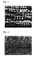
- FIG. 1 is a photomicrograph illustrating the microstructure of the invention.
- FIG. 2 is a photomicrograph illustrating the microstructure of a prior art alloy.
- FIGS. 3-5 are energy dispersive spectra for illustrating certain aspects of the invention, as described below.
- FIG. 6 is a graph comparing the high temperature wear resistance data from the Plint test.
- FIG. 7 is a graph comparing the coefficient of friction of the alloys tested in Example 6.
- FIG. 8 is a graph showing the thickness of the reaction layer from Example 7's corrosion resistance test.
- FIG. 9 is a graph showing the corrosion rate, in mm/year, from Example 8's H 2 SO 4 corrosion resistance test.
- FIG. 10 is a graph showing the corrosion rate, in mm/year, from Example 8's HCl corrosion resistance test.
- FIG. 11 is a graph showing the impact toughness results from Example 9.
- Chromium is provided in the alloys of the invention to enhance corrosion resistance.
- the Cr content is preferably in the range of about 12% to 18%. All percentages herein are by weight unless specified otherwise. A minimum of about 12% Cr is required to provide adequate corrosion resistance. The Cr content is maintained below about 18% because it has been discovered that other brittle intermetallics may tend to form at Cr contents above about 18%.
- the concentration of Cr is between about 14 wt % and about 17 wt %. In one preferred embodiment, the concentration of Cr is about 16.2 wt %.
- Silicon is provided in the alloys of the invention to impart wear resistance in combination with Mo.
- This Si content is appreciably lower - on the order of more than 40% lower, relatively - than the Si content of analogous prior Laves phase alloys.
- the Si content is preferably in the range of about 0.5% to 1.5%.
- the Si content is at least about 0.5% to provide enough Si for the formation of Laves phase.
- the Si content is maintained below about 1.5% in order to avoid or at least minimize the manifestation of Laves phase as blocky particles.
- the concentration of Si is between about 0.75 wt % and about 1.35 wt %. In one preferred embodiment, the concentration of Si is about 1.27 wt %.
- Molybdenum is provided in the alloys of the invention in an amount up to about 28% to impart wear resistance. It has been discovered that if the Mo content is greater than about 28%, other brittle intermetallics may form. A further requirement on the Mo content is that it be at least about 12% to provide sufficient wear resistance. Therefore, the concentration of Mo in the alloy is between about 12 wt % and about 28 wt %. For example, the concentration of Mo is between about 18 wt % and about 24 wt %. In one preferred embodiment, the concentration of Mo is about 22.3 wt %. Within these guidelines, the Mo content is selected as a function of the Si content. In particular, Mo is selected to provide a Mo:Si weight percent ratio of between about 15:1 and about 22:1.
- the Mo content must be independently satisfied in that, e.g., when the Si content is 0.5%, the Mo content must still be at least about 12%, even though an amount as low as 7.5% would satisfy the Mo:Si range of 15:1-22:1. Similarly, when the Si content is about 1.5%, the Mo content cannot be higher than about 28%, even though an amount as high as 33% would satisfy the Mo:Si range. And when the Si content is 1%, the Mo content must be between about 15 and 22%, and cannot be as high as 28%; though 28% is acceptable when the Si content is, e.g., 1.27%. In one embodiment, the Mo:Si ratio is between about 16:1 to about 19:1. In one preferred embodiment, the Mo:Si ratio is about 17.6:1.
- Cobalt is provided in the alloys as the alloy matrix. Cobalt is selected because it can be alloyed with the elements Cr, Mo, and Si and tends to form a tough matrix. Cobalt is selected over Ni, Fe, combinations thereof, and combinations thereof with Co because it has been discovered that a matrix which consists essentially of Co is tougher and less brittle than a matrix which contains some Ni and/or Fe.
- the Co content is preferably in the range of 51 to 75%.
- One preferred embodiment employs about 59% Co.
- Carbon is employed in the alloys to balance the Mo partition in the Laves phase by tying up a portion of the Mo as carbides. It has been found that carbon plays a role in resulting in a desirable microstructure. Carbon is believed to also function to form nucleation sites for the Laves phase. Carbon is therefore employed in an amount of at least about 0.1%. Carbon is maintained below about 1%, because it is thought that above about 1% excessive carbide formation would retard the formation of Laves phase. Therefore, the C has a concentration between about 0.1% and about 1%. In one such embodiment, the C has a concentration between about 0.1 wt % and about 0.5 wt %. In one preferred embodiment, the C concentration is about 0.21 wt %.
- Certain trace elements are present in the alloys of the invention due to the presence of such elements in scrap and otherwise due to the manufacturing process. These elements are not intentionally added, but are tolerable. Nickel may be present up to about 3%. Iron may be present up to about 3%. Boron may be intentionally present up to about 1% to enhance the alloy's molten state fluidity, fusing characteristics, or sintering properties. While the combination of these element tolerances is up to 8%, in a preferred embodiment the total trace element content is no more than 2%.
- Grain refiners V, Zr, Hf, Nb, Ta, and/or rare earth elements are optionally included in amounts up to about 2% cumulatively for microstructure refinement.
- a further aspect of the invention in certain embodiments is that the alloy is Mn-free, Cu-free, and free of all alloying elements having a material effect on metallurgical properties other than Cr, Mo, Si, and C in the Co matrix.
- the alloy is free of all alloying elements having a material effect on metallurgical properties other than Cr, Mo, Si, C, and the aforementioned grain refiners in the Co matrix.
- the hardness of the alloy is between about 40 and about 52 HRC (Rockwell C scale).
- the microstructure of the invention typically consists of 8-30% by volume Laves phase, depending on the chemical composition and cooling rate.
- the alloys of the invention are provided in the form of powder for deposition by plasma transfer arc welding deposition, laser cladding, plasma spraying, and high velocity oxyfuel spraying.
- the alloys can also be provided in the form of welding rods, wires, and electrodes for deposition by gas tungsten arc welding, shielded metal arc welding, or gas metal arc welding.
- the alloys are also provided in the form of castings and powder metallurgical components.
- alloy encompasses the metallic composition as an alloy in the classic metallurgical sense in that its elemental metal constituents have been melted together and coalesced, and also encompasses the metallic composition as a powder blend, a tubular wire containing powder, and the like which has not yet been melted together and coalesced.
- the alloy exhibits lower crack sensitivity than comparable Laves phase alloys. If an alloy has high crack sensitivity, the substrate must be preheated before applying the alloy as a coating to prevent fractures resulting from a significant temperature difference between the substrate and the molten alloy. Applications of the alloy of the invention do not necessarily require this preheating step.
- Example 1 The alloys of Example 1 were tested for hardness by conventional Rockwell testing (HRC), and were tested for cracking sensitivity by plasma transferred arc welding using 170-200 amps at 22 volts with a powder feed rate of 25-32 grams per minute and a travel speed of 100-135 mm/minute. The following results were obtained:
- FIG. 1 is a back-scattered image which illustrates the dendrites as dark areas and the interdendritic regions as light areas. This illustrates that the microstructure is hypoeutectic.
- a hypoeutectic microstructure is generally more ductile than a hypereutectic one. This microstructure is in contrast to conventional Laves phase microstructure such as FIG. 2 in U.S. Pat. No. 6,066,191, reproduced here as FIG. 2 , which includes a number of blocky, flower-like Laves phase particles.
- FIG. 3 An energy dispersive spectrum presented in FIG. 3 was generated of the interdendritic (light) region of Alloy 3, and one presented in FIG. 4 was generated for the dendritic (dark) region of the alloy. These reveal a greater concentration of Mo and Si in the interdendritic (light) region. Since the greater Mo and Si content is known to correspond to hard Laves particles, the greater concentration of Mo and Si in the interdendritic (light) regions indicates the presence of Laves phase in those interdendritic (light) regions.
- the Alloy 3 weld deposit was then examined by X-Ray diffraction, and the results presented in FIG. 5 .
- the location of the peaks in FIG. 5 demonstrate Laves phase forms CoMoSi and Co 3 Mo 2 Si. This corresponds to an AB 2 composition of Laves phase, with Mo as the A atoms and Co and Si as the B atoms.
- Alloy 3, T-400, and T-800 of Example 1 were tested for corrosion resistance by immersing a sample of each in a 0.22%-Al Zn bath saturated with Fe at 470° C. for 168 hours. The results of this test are shown in FIG. 8 . The data shows that Alloy 3 exhibits superior corrosion resistance. As such, the alloy of this invention is well suited for use on Zn galvanizing rolls and on stabilizing rolls for Zn galvanizing.
- the nominal composition of T-400C is shown above in Example 6.
- the results of corrosion tests conducted according to test procedure ASTM G31-72 are illustrated in FIGS. 9 and 10 .
- FIG. 9 shows the results of the test where a sample of each alloy was immersed in a 10% H 2 SO 4 solution at boiling (about 102° C.) according to ASTM G31-72.
- FIG. 10 shows the results of the test where a sample of each alloy was immersed in a 5% HCl solution at 66° C.
- the data show that Alloy 3 exhibits desirable corrosion resistance in each environment.
- Alloy 3 demonstrates corrosion resistance in H 2 SO 4 characterized by less than about 1.0 mm/year thickness loss.
- Alloy 3 demonstrates corrosion resistance in HCl characterized by less than about 0.08 mm/year thickness loss.
- the data from this test is shown in FIG. 11 .
- the data shows that Alloy 3 exhibits superior impact resistance, and therefore superior toughness, than comparable Laves phase alloys.
- the Alloy 3 sample shows an impact resistance of at least about 4.5 ft-lb under the ASTM E23-96 test.
- Alloy 3 from Example 1 was applied to a substrate to form an overlay, whereby the final component's wear and corrosion resistance were improved relative to the untreated substrate.
- Alloy 3 was used in the preparation of a roller for a Zn galvanizing operation.
- the preparation included forming a new overlay on the roller, while in another preferred embodiment, the preparation included rework or repair of an existing overlay.
- the roller was approximately 8 inches in diameter and 72 inches long.
- Plasma transferred arc welding was used to apply Alloy 3 in powder form to the roller's surface. Heat sufficient to melt Alloy 3 was generated to form a weld pool on the roller. The weld pool comprised molten Alloy 3 as well as some molten substrate material.
- the roller was 316 stainless steel.
- the arc and source of Alloy 3 powder were maneuvered over the roller's surface such that the weld pool solidified in a substantially continuous and uniform overlay.
- the overlay surface was then finished to provide a smooth surfaced roller.
Abstract
Description
| Cr | Mo | Si | C | Co | Mo: | ||
| Alloy |
| 1 | 14.1 | 27 | 1.03 | 0.004 | 53.9 | 26.2 | |
| | 15.2 | 25.4 | 1.01 | 0.10 | 57.7 | 25.1 | |
| | 16.2 | 22.3 | 1.27 | 0.21 | 59.6 | 17.6 | |
| T-400 | 8.5 | 28 | 2.6 | 0.04 | 59.9 | 10.8 | |
| T-800 | 17 | 28 | 3.3 | 0.04 | 50.7 | 8.5 | |
The powders were screened to a size of 45 to 150 microns and applied to a substrate by plasma transferred arc welding.
| Cracking | ||||
| HRC | Sensitivity | Mo: | ||
| Alloy |
| 1 | 55 | High | 26.2 | |
| | 49 | Medium | 25.1 | |
| | 48 | Low | 17.6 | |
| T-400 | 52 | Medium | 10.8 | |
| T-800 | 58 | High | 8.5 | |
These results demonstrate that the ratio of Mo:Si has a profound effect on alloy ductility, with substantially enhanced crack sensitivity performance achieved by
| Cr | Mo | Si | C | Ni | Fe | Co | Mo:Si | ||
| A286 | 14.8 | 1.3 | 1.0 | 0.8 | 25.5 | |
0 | 1.3 |
| 310SS | 25 | 0 | 1.5 | 0.08 | 20.5 | |
0 | 0 |
| XEV-F | 22.2 | 0.35 | 0.3 | 0.5 | 3.5 | |
0 | 1.2 |
| 440C | 18 | 0.75 | 1.0 | 1.2 | 0 | |
0 | 0.75 |
| X-5000 | 22.5 | 7.0 | 0.3 | 0.75 | 4.0 | |
10 | 23.3 |
| T-506 | 35 | 0 | 1 | 1.6 | 0 | 0 | Bal | 0 |
| T-400 | 8.5 | 28 | 2.6 | 0.04 | 0 | 0 | Bal | 10.8 |
| T-401 | 16.2 | 22.3 | 1.27 | 0.21 | 0 | 0 | Bal | 17.6 |
| T- |
14 | 26 | 2.6 | 0.08 | 0 | 0 | Bal | 10.0 |
Claims (19)
Priority Applications (1)
| Application Number | Priority Date | Filing Date | Title |
|---|---|---|---|
| US11/015,129 US7572408B2 (en) | 2003-12-29 | 2004-12-17 | Ductile cobalt-based Laves phase alloys |
Applications Claiming Priority (2)
| Application Number | Priority Date | Filing Date | Title |
|---|---|---|---|
| US53306503P | 2003-12-29 | 2003-12-29 | |
| US11/015,129 US7572408B2 (en) | 2003-12-29 | 2004-12-17 | Ductile cobalt-based Laves phase alloys |
Publications (2)
| Publication Number | Publication Date |
|---|---|
| US20050142026A1 US20050142026A1 (en) | 2005-06-30 |
| US7572408B2 true US7572408B2 (en) | 2009-08-11 |
Family
ID=34748848
Family Applications (1)
| Application Number | Title | Priority Date | Filing Date |
|---|---|---|---|
| US11/015,129 Active US7572408B2 (en) | 2003-12-29 | 2004-12-17 | Ductile cobalt-based Laves phase alloys |
Country Status (5)
| Country | Link |
|---|---|
| US (1) | US7572408B2 (en) |
| EP (1) | EP1704263B1 (en) |
| AU (1) | AU2004311779A1 (en) |
| CA (1) | CA2555385A1 (en) |
| WO (1) | WO2005065222A2 (en) |
Cited By (2)
| Publication number | Priority date | Publication date | Assignee | Title |
|---|---|---|---|---|
| US11155904B2 (en) | 2019-07-11 | 2021-10-26 | L.E. Jones Company | Cobalt-rich wear resistant alloy and method of making and use thereof |
| US20240018630A1 (en) * | 2022-05-25 | 2024-01-18 | Kennametal Inc. | Wear and corrosion resistant alloy compositions |
Families Citing this family (13)
| Publication number | Priority date | Publication date | Assignee | Title |
|---|---|---|---|---|
| CA2588988A1 (en) * | 2004-11-30 | 2006-06-08 | Deloro Stellite Holdings Corporation | Weldable, crack-resistant co-based alloy |
| JP5529366B2 (en) * | 2007-03-29 | 2014-06-25 | 三菱重工業株式会社 | Coating material, method for producing the same, coating method, and blade with shroud |
| DE112008001868T5 (en) * | 2007-07-16 | 2010-07-22 | Deloro Stellite Holdings Corp. | Weldable, fracture-resistant, Co-based alloy, application process and components |
| CN103189532A (en) * | 2010-11-09 | 2013-07-03 | 福田金属箔粉工业株式会社 | Wear-resistant cobalt-based alloy and engine valve coated with same |
| PL2639324T3 (en) | 2010-11-09 | 2017-06-30 | Fukuda Metal Foil & Powder Co., Ltd. | High-toughness cobalt-based alloy and engine valve coated with same |
| JP5742447B2 (en) * | 2011-05-09 | 2015-07-01 | 大同特殊鋼株式会社 | High hardness overlaying alloy powder |
| US9289037B2 (en) | 2011-10-20 | 2016-03-22 | Mythrial Metals Llc | Hardened cobalt based alloy jewelry and related methods |
| CN103741049A (en) * | 2014-01-21 | 2014-04-23 | 湘潭大学 | Iron-based abrasion-resistant alloy based on Laves phase strengthening and preparation method thereof |
| CN106591761B (en) * | 2015-10-14 | 2020-08-11 | 上海宝钢工业技术服务有限公司 | Method for preparing composite coating resisting molten metal erosion |
| JP6671772B2 (en) * | 2015-12-22 | 2020-03-25 | 山陽特殊製鋼株式会社 | High hardness and toughness powder |
| CN110102570B (en) * | 2019-06-17 | 2021-01-22 | 江苏省沙钢钢铁研究院有限公司 | High-temperature alloy wire rod and high-speed wire rolling method thereof |
| JP6940801B1 (en) * | 2020-12-25 | 2021-09-29 | 千住金属工業株式会社 | Sliding member, bearing, manufacturing method of sliding member, manufacturing method of bearing |
| CN113981440A (en) * | 2021-10-28 | 2022-01-28 | 马鞍山马钢电气修造有限公司 | Method for repairing surface modification technology of plunger rod of high-pressure plug pump |
Citations (26)
| Publication number | Priority date | Publication date | Assignee | Title |
|---|---|---|---|---|
| US2030342A (en) | 1933-07-15 | 1936-02-11 | Union Carbide & Carbon Corp | Alloy |
| GB867455A (en) * | 1958-04-24 | 1961-05-10 | Metco Inc | Improvements relating to the production of carbide-containing sprayweld coatings |
| US3180012A (en) | 1963-07-12 | 1965-04-27 | Du Pont | Cobalt alloys |
| US3244506A (en) * | 1964-09-08 | 1966-04-05 | Allegheny Ludhum Steel Corp | Cutting tool material |
| US3257178A (en) | 1966-06-21 | Coated metal article | ||
| US3331700A (en) | 1963-04-01 | 1967-07-18 | Du Pont | Method of coating metals |
| US3361560A (en) | 1966-04-19 | 1968-01-02 | Du Pont | Nickel silicon and refractory metal alloy |
| US3410732A (en) * | 1965-04-30 | 1968-11-12 | Du Pont | Cobalt-base alloys |
| US3795430A (en) | 1972-10-19 | 1974-03-05 | Du Pont | Wear resistant frictionally contacting surfaces |
| US3839024A (en) * | 1973-02-15 | 1974-10-01 | Du Pont | Wear and corrosion resistant alloy |
| USRE28552E (en) * | 1965-04-30 | 1975-09-16 | Cobalt-base alloys | |
| US4453976A (en) | 1982-08-25 | 1984-06-12 | Alloy Metals, Inc. | Corrosion resistant thermal spray alloy and coating method |
| US4465515A (en) | 1980-08-02 | 1984-08-14 | M.A.N. Maschinenfabrik Augsburg-Nurnsberg Aktiengesellschaft | Piston ring for internal combustion engine |
| US4529616A (en) | 1982-08-25 | 1985-07-16 | Alloy Metals, Inc. | Method of forming corrosion resistant coating |
| US4618474A (en) * | 1985-01-25 | 1986-10-21 | Asahi Fiber Glass Company, Limited | Co-base heat resistant alloy |
| US4692305A (en) * | 1985-11-05 | 1987-09-08 | Perkin-Elmer Corporation | Corrosion and wear resistant alloy |
| JPH04254542A (en) | 1991-02-06 | 1992-09-09 | Kubota Corp | Cobalt-base alloy having corrosion resistance and wear resistance |
| JPH0617177A (en) * | 1992-07-01 | 1994-01-25 | Kubota Corp | Corrosion and wear resistant co-based alloy |
| JPH07126782A (en) * | 1993-11-04 | 1995-05-16 | Mitsubishi Materials Corp | Mouthpiece for secondary combustion chamber for diesel engine, made of co-base heat resistant alloy |
| US5855699A (en) | 1994-10-03 | 1999-01-05 | Daido Tokushuko Kabushiki Kaisha | Method for manufacturing welded clad steel tube |
| US6066191A (en) | 1997-05-21 | 2000-05-23 | Kabushiki Kaisha Toyota Chuo Kenkyusho | Hard molybdenum alloy, wear resistant alloy and method for manufacturing the same |
| EP1024209A1 (en) | 1999-01-28 | 2000-08-02 | Praxair S.T. Technology, Inc. | Thermal spray coating for gates and seats |
| US6331688B1 (en) | 1996-09-23 | 2001-12-18 | Höganás AB | Use of a metal powder for surface coating by submerged arc welding |
| US6479014B1 (en) | 1999-07-27 | 2002-11-12 | Deloro Stellite Company, Inc. | Saw blade tips and alloys therefor |
| US20020168285A1 (en) | 2000-10-27 | 2002-11-14 | Blake Wayne C. | Cobalt-based hard facing alloy |
| US20040219354A1 (en) | 2003-05-02 | 2004-11-04 | Deloro Stellite Company | Wear-resistant, corrosion-resistant Ni-Cr-Mo thermal spray powder and method |
Family Cites Families (7)
| Publication number | Priority date | Publication date | Assignee | Title |
|---|---|---|---|---|
| JPH0759730B2 (en) * | 1988-04-21 | 1995-06-28 | 株式会社クボタ | Corrosion and wear resistant alloys for plastic injection molding and extrusion machines |
| JP2745646B2 (en) * | 1989-03-08 | 1998-04-28 | 三菱マテリアル株式会社 | Method for producing high-temperature wear-resistant Co-based alloy with excellent hot workability |
| JP2800074B2 (en) * | 1991-02-06 | 1998-09-21 | 株式会社クボタ | Corrosion and wear resistant cobalt based alloy |
| JP3287865B2 (en) * | 1991-09-27 | 2002-06-04 | トヨタ自動車株式会社 | Cobalt-based alloy with excellent wear resistance and aggressiveness |
| JPH0617176A (en) * | 1992-07-01 | 1994-01-25 | Kubota Corp | Corrosion and wear resistant co-based alloy |
| JPH0718350A (en) * | 1993-07-07 | 1995-01-20 | Kubota Corp | Production of co-based sintered alloy |
| JPH07300642A (en) * | 1994-04-27 | 1995-11-14 | Nittetsu Hard Kk | Coating material and metal bath immersion member coated with this material |
-
2004
- 2004-12-17 CA CA002555385A patent/CA2555385A1/en not_active Abandoned
- 2004-12-17 US US11/015,129 patent/US7572408B2/en active Active
- 2004-12-17 WO PCT/US2004/042771 patent/WO2005065222A2/en active Application Filing
- 2004-12-17 AU AU2004311779A patent/AU2004311779A1/en not_active Abandoned
- 2004-12-17 EP EP04814903.3A patent/EP1704263B1/en active Active
Patent Citations (26)
| Publication number | Priority date | Publication date | Assignee | Title |
|---|---|---|---|---|
| US3257178A (en) | 1966-06-21 | Coated metal article | ||
| US2030342A (en) | 1933-07-15 | 1936-02-11 | Union Carbide & Carbon Corp | Alloy |
| GB867455A (en) * | 1958-04-24 | 1961-05-10 | Metco Inc | Improvements relating to the production of carbide-containing sprayweld coatings |
| US3331700A (en) | 1963-04-01 | 1967-07-18 | Du Pont | Method of coating metals |
| US3180012A (en) | 1963-07-12 | 1965-04-27 | Du Pont | Cobalt alloys |
| US3244506A (en) * | 1964-09-08 | 1966-04-05 | Allegheny Ludhum Steel Corp | Cutting tool material |
| US3410732A (en) * | 1965-04-30 | 1968-11-12 | Du Pont | Cobalt-base alloys |
| USRE28552E (en) * | 1965-04-30 | 1975-09-16 | Cobalt-base alloys | |
| US3361560A (en) | 1966-04-19 | 1968-01-02 | Du Pont | Nickel silicon and refractory metal alloy |
| US3795430A (en) | 1972-10-19 | 1974-03-05 | Du Pont | Wear resistant frictionally contacting surfaces |
| US3839024A (en) * | 1973-02-15 | 1974-10-01 | Du Pont | Wear and corrosion resistant alloy |
| US4465515A (en) | 1980-08-02 | 1984-08-14 | M.A.N. Maschinenfabrik Augsburg-Nurnsberg Aktiengesellschaft | Piston ring for internal combustion engine |
| US4453976A (en) | 1982-08-25 | 1984-06-12 | Alloy Metals, Inc. | Corrosion resistant thermal spray alloy and coating method |
| US4529616A (en) | 1982-08-25 | 1985-07-16 | Alloy Metals, Inc. | Method of forming corrosion resistant coating |
| US4618474A (en) * | 1985-01-25 | 1986-10-21 | Asahi Fiber Glass Company, Limited | Co-base heat resistant alloy |
| US4692305A (en) * | 1985-11-05 | 1987-09-08 | Perkin-Elmer Corporation | Corrosion and wear resistant alloy |
| JPH04254542A (en) | 1991-02-06 | 1992-09-09 | Kubota Corp | Cobalt-base alloy having corrosion resistance and wear resistance |
| JPH0617177A (en) * | 1992-07-01 | 1994-01-25 | Kubota Corp | Corrosion and wear resistant co-based alloy |
| JPH07126782A (en) * | 1993-11-04 | 1995-05-16 | Mitsubishi Materials Corp | Mouthpiece for secondary combustion chamber for diesel engine, made of co-base heat resistant alloy |
| US5855699A (en) | 1994-10-03 | 1999-01-05 | Daido Tokushuko Kabushiki Kaisha | Method for manufacturing welded clad steel tube |
| US6331688B1 (en) | 1996-09-23 | 2001-12-18 | Höganás AB | Use of a metal powder for surface coating by submerged arc welding |
| US6066191A (en) | 1997-05-21 | 2000-05-23 | Kabushiki Kaisha Toyota Chuo Kenkyusho | Hard molybdenum alloy, wear resistant alloy and method for manufacturing the same |
| EP1024209A1 (en) | 1999-01-28 | 2000-08-02 | Praxair S.T. Technology, Inc. | Thermal spray coating for gates and seats |
| US6479014B1 (en) | 1999-07-27 | 2002-11-12 | Deloro Stellite Company, Inc. | Saw blade tips and alloys therefor |
| US20020168285A1 (en) | 2000-10-27 | 2002-11-14 | Blake Wayne C. | Cobalt-based hard facing alloy |
| US20040219354A1 (en) | 2003-05-02 | 2004-11-04 | Deloro Stellite Company | Wear-resistant, corrosion-resistant Ni-Cr-Mo thermal spray powder and method |
Non-Patent Citations (14)
| Title |
|---|
| Abstract of JP01272738; Oct. 31, 1989. |
| Abstract of JP02236239; Sep. 19, 1990. |
| Abstract of JP04254541; Sep. 9, 1992. |
| Abstract of JP04-254542; Sep. 9, 1992. |
| Abstract of JP05084592; Apr. 6, 1993. |
| Abstract of JP06017176; Jan. 25, 1994. |
| Abstract of JP07018350; Jan. 20, 1995. |
| Abstract of JP07300642; Nov. 14, 1995. |
| ASM International, Materials Park, Ohio, Properties and Selection: Nonferrous Alloys and Special-Purpose Materials: "Rare Earth Metals", pp. 727-728, Oct. 1990. * |
| ASTM Designation: E23-96, Standard Test Methods for Notched Bar Impact Testing of Metallic Materials, 1996. |
| ASTM Designation: G133-95, Standard Test Method for Linearly Reciprocating Ball-on-Flat Sliding Wear, 1995. |
| European Search Report, EP04814903; Apr. 27, 2009, 4 pages. |
| International Search Report, PCT/US2004/042771; dated Mar. 28, 2007; 4 pages. |
| Standard Practice for Laboratory Immersion Corrsion Testing of Metals, The American Society for Testing and Materials, Designation: G 31-72, pp. 95-102, (Reapproved 1995). |
Cited By (2)
| Publication number | Priority date | Publication date | Assignee | Title |
|---|---|---|---|---|
| US11155904B2 (en) | 2019-07-11 | 2021-10-26 | L.E. Jones Company | Cobalt-rich wear resistant alloy and method of making and use thereof |
| US20240018630A1 (en) * | 2022-05-25 | 2024-01-18 | Kennametal Inc. | Wear and corrosion resistant alloy compositions |
Also Published As
| Publication number | Publication date |
|---|---|
| EP1704263B1 (en) | 2018-09-26 |
| EP1704263A2 (en) | 2006-09-27 |
| WO2005065222A2 (en) | 2005-07-21 |
| US20050142026A1 (en) | 2005-06-30 |
| AU2004311779A1 (en) | 2005-07-21 |
| EP1704263A4 (en) | 2009-06-03 |
| WO2005065222A3 (en) | 2007-06-14 |
| CA2555385A1 (en) | 2005-07-21 |
Similar Documents
| Publication | Publication Date | Title |
|---|---|---|
| US8603264B2 (en) | Weldable, crack-resistant Co-based alloy and overlay | |
| Gholipour et al. | Microstructure and wear behavior of stellite 6 cladding on 17-4 PH stainless steel | |
| US7572408B2 (en) | Ductile cobalt-based Laves phase alloys | |
| Shin et al. | Effect of molybdenum on the microstructure and wear resistance of cobalt-base Stellite hardfacing alloys | |
| US7645493B2 (en) | Composite wires for coating substrates and methods of use | |
| EP2787095B1 (en) | Ni-fe-cr alloy and engine valve welded or coated with the same alloy | |
| US7815756B2 (en) | Build-up wear-resistant copper-based alloy | |
| Branagan et al. | High toughness high hardness iron based PTAW weld materials | |
| US10458006B2 (en) | Powder composition and use thereof | |
| Jeshvaghani et al. | Microstructural study and wear behavior of ductile iron surface alloyed by Inconel 617 | |
| US4216015A (en) | Wear-resistant iron-nickel-cobalt alloys | |
| US9051631B2 (en) | Weldable, crack-resistant co-based alloy, overlay method, and components | |
| EP2639324B1 (en) | High-toughness cobalt-based alloy and engine valve coated with same | |
| Ferozhkhan et al. | Metallurgical study of Stellite 6 cladding on 309-16L stainless steel | |
| CA3003905C (en) | Layered construction of in-situ metal matrix composites | |
| Ding et al. | Effect of Mo and nano-Nd 2 O 3 on the microstructure and wear resistance of laser cladding Ni-based alloy coatings | |
| EP0039450B1 (en) | Hard facing nickel-base alloy | |
| KR20070017999A (en) | Ductile cobalt-based laves phase alloys | |
| Tongov | Surfacing–Technologies and Layer Properties (a Review) | |
| Harati et al. | Microstructural analysis of laser cladding of stellite 6 on ductile iron |
Legal Events
| Date | Code | Title | Description |
|---|---|---|---|
| AS | Assignment |
Owner name: DELORO STELLITE HOLDINGS CORPORATION, MISSOURI Free format text: ASSIGNMENT OF ASSIGNORS INTEREST;ASSIGNORS:YAO, MATTHEW X.;WU, JAMES B. C.;REEL/FRAME:015790/0809;SIGNING DATES FROM 20050121 TO 20050131 |
|
| AS | Assignment |
Owner name: THE ROYAL BANK OF SCOTLAND, PLC, AS AGENT AND AS T Free format text: SECURITY AGREEMENT;ASSIGNOR:DELORO STELLITE HOLDINGS CORPORATION;REEL/FRAME:017606/0727 Effective date: 20060404 |
|
| STCF | Information on status: patent grant |
Free format text: PATENTED CASE |
|
| FPAY | Fee payment |
Year of fee payment: 4 |
|
| SULP | Surcharge for late payment | ||
| AS | Assignment |
Owner name: DELORO STELLITE HOLDINGS CORPORATION, MISSOURI Free format text: RELEASE BY SECURED PARTY;ASSIGNOR:THE ROYAL BANK OF SCOTLAND;REEL/FRAME:030055/0903 Effective date: 20130315 |
|
| AS | Assignment |
Owner name: KENNAMETAL INC., PENNSYLVANIA Free format text: ASSIGNMENT OF ASSIGNORS INTEREST;ASSIGNOR:DELORO STELLITE HOLDINGS CORPORATION;REEL/FRAME:030544/0642 Effective date: 20130604 |
|
| FEPP | Fee payment procedure |
Free format text: PAYOR NUMBER ASSIGNED (ORIGINAL EVENT CODE: ASPN); ENTITY STATUS OF PATENT OWNER: LARGE ENTITY |
|
| FPAY | Fee payment |
Year of fee payment: 8 |
|
| MAFP | Maintenance fee payment |
Free format text: PAYMENT OF MAINTENANCE FEE, 12TH YEAR, LARGE ENTITY (ORIGINAL EVENT CODE: M1553); ENTITY STATUS OF PATENT OWNER: LARGE ENTITY Year of fee payment: 12 |