US7584574B2 - Sliding window assembly having a removable sliding panel - Google Patents
Sliding window assembly having a removable sliding panel Download PDFInfo
- Publication number
- US7584574B2 US7584574B2 US10/928,048 US92804804A US7584574B2 US 7584574 B2 US7584574 B2 US 7584574B2 US 92804804 A US92804804 A US 92804804A US 7584574 B2 US7584574 B2 US 7584574B2
- Authority
- US
- United States
- Prior art keywords
- sliding panel
- window assembly
- track member
- sliding
- sliding window
- Prior art date
- Legal status (The legal status is an assumption and is not a legal conclusion. Google has not performed a legal analysis and makes no representation as to the accuracy of the status listed.)
- Active, expires
Links
Images


Classifications
-
- B—PERFORMING OPERATIONS; TRANSPORTING
- B60—VEHICLES IN GENERAL
- B60J—WINDOWS, WINDSCREENS, NON-FIXED ROOFS, DOORS, OR SIMILAR DEVICES FOR VEHICLES; REMOVABLE EXTERNAL PROTECTIVE COVERINGS SPECIALLY ADAPTED FOR VEHICLES
- B60J1/00—Windows; Windscreens; Accessories therefor
- B60J1/18—Windows; Windscreens; Accessories therefor arranged at the vehicle rear
- B60J1/1838—Windows; Windscreens; Accessories therefor arranged at the vehicle rear movable for non-convertible vehicles, including vehicles with versatile load area
- B60J1/1846—Windows; Windscreens; Accessories therefor arranged at the vehicle rear movable for non-convertible vehicles, including vehicles with versatile load area where the window can slide
- B60J1/1853—Windows; Windscreens; Accessories therefor arranged at the vehicle rear movable for non-convertible vehicles, including vehicles with versatile load area where the window can slide horizontally in direction transverse to vehicle longitudinal axis
-
- B—PERFORMING OPERATIONS; TRANSPORTING
- B60—VEHICLES IN GENERAL
- B60J—WINDOWS, WINDSCREENS, NON-FIXED ROOFS, DOORS, OR SIMILAR DEVICES FOR VEHICLES; REMOVABLE EXTERNAL PROTECTIVE COVERINGS SPECIALLY ADAPTED FOR VEHICLES
- B60J1/00—Windows; Windscreens; Accessories therefor
- B60J1/18—Windows; Windscreens; Accessories therefor arranged at the vehicle rear
- B60J1/1838—Windows; Windscreens; Accessories therefor arranged at the vehicle rear movable for non-convertible vehicles, including vehicles with versatile load area
- B60J1/1846—Windows; Windscreens; Accessories therefor arranged at the vehicle rear movable for non-convertible vehicles, including vehicles with versatile load area where the window can slide
- B60J1/1861—Windows; Windscreens; Accessories therefor arranged at the vehicle rear movable for non-convertible vehicles, including vehicles with versatile load area where the window can slide vertically, e.g. into lower part of rear door before opening rear door
-
- E—FIXED CONSTRUCTIONS
- E05—LOCKS; KEYS; WINDOW OR DOOR FITTINGS; SAFES
- E05D—HINGES OR SUSPENSION DEVICES FOR DOORS, WINDOWS OR WINGS
- E05D15/00—Suspension arrangements for wings
- E05D15/06—Suspension arrangements for wings for wings sliding horizontally more or less in their own plane
- E05D15/0621—Details, e.g. suspension or supporting guides
- E05D15/0626—Details, e.g. suspension or supporting guides for wings suspended at the top
- E05D15/0652—Tracks
-
- E—FIXED CONSTRUCTIONS
- E05—LOCKS; KEYS; WINDOW OR DOOR FITTINGS; SAFES
- E05D—HINGES OR SUSPENSION DEVICES FOR DOORS, WINDOWS OR WINGS
- E05D15/00—Suspension arrangements for wings
- E05D15/06—Suspension arrangements for wings for wings sliding horizontally more or less in their own plane
- E05D15/10—Suspension arrangements for wings for wings sliding horizontally more or less in their own plane movable out of one plane into a second parallel plane
- E05D15/1042—Suspension arrangements for wings for wings sliding horizontally more or less in their own plane movable out of one plane into a second parallel plane with transversely moving carriage
- E05D15/1047—Suspension arrangements for wings for wings sliding horizontally more or less in their own plane movable out of one plane into a second parallel plane with transversely moving carriage specially adapted for vehicles
-
- E—FIXED CONSTRUCTIONS
- E05—LOCKS; KEYS; WINDOW OR DOOR FITTINGS; SAFES
- E05D—HINGES OR SUSPENSION DEVICES FOR DOORS, WINDOWS OR WINGS
- E05D15/00—Suspension arrangements for wings
- E05D15/16—Suspension arrangements for wings for wings sliding vertically more or less in their own plane
-
- E—FIXED CONSTRUCTIONS
- E05—LOCKS; KEYS; WINDOW OR DOOR FITTINGS; SAFES
- E05D—HINGES OR SUSPENSION DEVICES FOR DOORS, WINDOWS OR WINGS
- E05D7/00—Hinges or pivots of special construction
- E05D7/10—Hinges or pivots of special construction to allow easy separation or connection of the parts at the hinge axis
- E05D7/1083—Hinges or pivots of special construction to allow easy separation or connection of the parts at the hinge axis facilitating simultaneous assembly of a plurality of hinges, e.g. for mounting heavy wings
- E05D2007/1088—Hinges or pivots of special construction to allow easy separation or connection of the parts at the hinge axis facilitating simultaneous assembly of a plurality of hinges, e.g. for mounting heavy wings using hinge pins having different lengths
-
- E—FIXED CONSTRUCTIONS
- E05—LOCKS; KEYS; WINDOW OR DOOR FITTINGS; SAFES
- E05D—HINGES OR SUSPENSION DEVICES FOR DOORS, WINDOWS OR WINGS
- E05D15/00—Suspension arrangements for wings
- E05D15/06—Suspension arrangements for wings for wings sliding horizontally more or less in their own plane
- E05D15/10—Suspension arrangements for wings for wings sliding horizontally more or less in their own plane movable out of one plane into a second parallel plane
- E05D15/1042—Suspension arrangements for wings for wings sliding horizontally more or less in their own plane movable out of one plane into a second parallel plane with transversely moving carriage
- E05D2015/1055—Suspension arrangements for wings for wings sliding horizontally more or less in their own plane movable out of one plane into a second parallel plane with transversely moving carriage with slanted or curved track sections or cams
-
- E—FIXED CONSTRUCTIONS
- E05—LOCKS; KEYS; WINDOW OR DOOR FITTINGS; SAFES
- E05Y—INDEXING SCHEME RELATING TO HINGES OR OTHER SUSPENSION DEVICES FOR DOORS, WINDOWS OR WINGS AND DEVICES FOR MOVING WINGS INTO OPEN OR CLOSED POSITION, CHECKS FOR WINGS AND WING FITTINGS NOT OTHERWISE PROVIDED FOR, CONCERNED WITH THE FUNCTIONING OF THE WING
- E05Y2900/00—Application of doors, windows, wings or fittings thereof
- E05Y2900/50—Application of doors, windows, wings or fittings thereof for vehicles
- E05Y2900/53—Application of doors, windows, wings or fittings thereof for vehicles characterised by the type of wing
- E05Y2900/55—Windows
Definitions
- the subject invention generally relates to a sliding window assembly, particularly for a vehicle, wherein a sliding panel is removable from the window assembly.
- the sliding window assembly disclosed in the '214 patent includes several embodiments.
- a sliding pane or panel having a rectangular shape, including a top and bottom is guided between an open and closed position.
- the sliding panel includes a member or pin extending from both the top and bottom of the sliding panel.
- the sliding window assembly includes a frame that has a top and bottom track member each defining a guide channel. Either the top or bottom pins are biased in a vertical direction to permit the pins to be retracted to enter or escape the guide channels.
- removal of the sliding panel can be accomplished by retracting the pins to create a clearance, which allows the sliding panel to be removed from the opposing guide channel.
- the pins must retract enough to create the clearance for the pins on the opposing side of the sliding panel to be completely removed from the guide channel. Because the pins in the '214 patent are biased and retractable, they are not rigid and are susceptible to movement in the vertical direction during movement of the sliding panel between the closed and open position. The vertical movement allowed by the pins increases the possibility of misalignment of the sliding panel and introduces a greater chance for rattle or undesirable vibration during the operation of the sliding window assembly.
- the '796 patent also discloses a sliding window assembly.
- the sliding window assembly of the '796 patent does focus primarily on a removable feature of panels in the sliding window assembly. More specifically, the sliding window assembly includes a rectangular frame having an upper and lower portion each including a plurality of adjacent track members opening inwards.
- the sliding window assembly further includes a plurality of sliding panels engaged in the track members that are able to slide horizontally to create an opening.
- the upper portion has an aperture for receiving a pin. The pin slides into the aperture and across the track member of the upper portion. The pin is engaged by a ball detent connected to the upper portion. The ball detent locks the pin in the aperture of the upper portion.
- the sliding panel is removed by retracting the pin and raising the sliding panel in the track member until the sliding panel is removed from engagement with the track member of the lower portion.
- the sliding panel is then tilted and lowered to remove the sliding panel from the track member of the upper portion.
- the pin is not continuous and only engages the sliding panel over a small length of the track member of the upper portion. This is undesirable due to the possibility of the panels being misaligned or rattling during the operation of the sliding window assembly or vehicle.
- the prior art does not address a sliding window assembly that supports the sliding panel on the track member to reduce the possibility of misalignment and vibration during the operation of the sliding window assembly. Furthermore, the prior art does not attain the required support for smooth operation of the sliding window while still allowing the sliding panel to be easily removed from the track members. Therefore, it is desirable to provide a sliding window assembly that combines a simple design to support the sliding panel without additional clearance to accommodate the removal of the sliding panel from the track member for installation or servicing of the sliding panel.
- the invention provides a sliding window assembly for a vehicle.
- the sliding window assembly includes a sliding panel and a track member defining a channel.
- the sliding panel has an edge and is moveable along the track member between an open position and a closed position.
- the sliding panel includes a shoe extending from the sliding panel into the channel for supporting the sliding panel on the track member as the sliding panel moves between the open and closed positions.
- the shoe has a shoe length parallel with the track member.
- the track member defines a gap that extends laterally into the channel and has a gap length along the track member. The shoe length is less than the gap length to allow the shoe to pass through the gap for removing the sliding panel from the channel of the track member.
- the combination of the shoe length and the gap length allows for easy removal of the sliding panel.
- the removal of the sliding window assembly is accomplished by aligning the shoe with the gap to provide a sliding window assembly having a sliding panel that can easily be replaced or serviced over the life of the sliding window assembly.
- the shoe engages the track member by extending into the channel of the track member to provide stable support for the sliding panel, to provide smooth movement free of rattles and vibrations as the sliding panel moves between the open and closed positions.
- FIG. 1 is a perspective view of a vehicle with a sliding window assembly implemented as a backlite of the vehicle;
- FIG. 2A is a perspective view of a preferred embodiment of the sliding window assembly with the sliding panel horizontally movable between an open and a closed position;
- FIG. 2B is a perspective view of an alternative embodiment of the sliding window assembly with the sliding panel vertically movable between the open and the closed position;
- FIG. 3A is an exploded view of the preferred embodiment of the sliding window assembly
- FIG. 3B is an exploded view of an alternative embodiment of a sliding window assembly
- FIG. 4 is a detailed partial perspective view of the sliding window assembly
- FIG. 5 is a detailed partial exploded side view of a sliding panel and track member
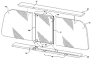
- FIG. 6 is a perspective view of the preferred embodiment of the sliding window assembly with the sliding panel removed from the assembly;
- FIG. 7 is a detailed partial perspective view of the sliding window assembly with the sliding panel in a closed position
- FIG. 8A is a partial cross-sectional view of the sliding panel engaged in the track member in the closed position taken along line 8 A- 8 A in FIG. 7 ;
- FIG. 8B is a partial cross-sectional view of the sliding panel engaged in the track member in a open position taken along line 8 B- 8 B in FIG. 4 ;
- FIG. 9A is a perspective view of the preferred embodiment of the sliding panel
- FIG. 9B is a perspective view of an alternative embodiment of the sliding panel with a shoe integrally molded about the sliding panel;
- FIGS. 9C and 9D are a perspective view of an alternative embodiment of the sliding panel with two shoes and two posts, one of each disposed on opposing edges;
- FIGS. 9E and 9F are a perspective view of an alternative embodiment of the sliding panel with two shoes disposed on an edge and two posts disposed on an opposing edge.
- a sliding window assembly is generally shown at 10 .
- the sliding window assembly 10 is shown in a vehicle 12 , specifically as a backlite in a pickup truck.
- the sliding window assembly 10 of the present invention can be implemented in other types of vehicles, as well as in non-vehicle applications.
- the sliding window assembly 10 includes a sliding panel 14 that moves between an open and a closed position.
- the sliding panel has an edge 15 , and in the preferred embodiment the sliding panel 14 is rectangular in shape having four edges 15 .
- the shape and orientation of the sliding panel 14 is adaptable as one skilled in the art would understand.
- the sliding window assembly 10 includes at least one fixed panel 16 , 18 that is fixed and disposed in the same plane as and abutting the sliding panel 14 in the closed position.
- the assembly further includes a pair of fixed panels 16 , 18 , i.e., a first and second fixed panel, in a spaced relationship defining an opening therebetween.
- the fixed panels 16 , 18 are operatively connected to a track member 20 , 22 , typically with an adhesive or other adequate connection methods.
- the track member 20 , 22 is described additionally below.
- the sliding panel 14 moves between the open and closed positions modifying the size of the opening defined by the fixed panels 16 , 18 .
- the sliding panel 14 and the fixed panels 16 , 18 are abutting in the same plane to create a flush and substantially uniform exterior appearance.
- the sliding panel 14 and the fixed panels 16 , 18 are preferably formed of glass, but may be formed of plastic, metal or any other suitable material.
- the preferred embodiment is a sliding widow assembly 10 , as shown in FIG. 2A , where the sliding panel 14 slides horizontally between the open and closed position.
- the sliding window assembly 10 can be applied independent of orientation, i.e., to both a horizontal and vertical sliding window assembly.
- FIG. 2B illustrates an alternative embodiment where the sliding window assembly 10 is adapted such that the sliding panel 14 slides vertically between the open and closed position.
- the preferred embodiment of the sliding window assembly 10 further includes a pair of the track members 20 , 22 .
- the pair of track members i.e., a first and second track member 20 , 22 , are disposed in opposing and parallel relationship along two opposite edges 15 of the sliding panel 14 .
- FIG. 3B illustrates an alternative embodiment where the track members 20 , 22 of the sliding window assembly 10 are adapted for orienting the sliding panel 14 for movement in the vertical direction.
- Each of the track members 20 , 22 further defines a channel 24 .
- the track member 20 , 22 includes a base 26 , a front wall 28 and a back wall 30 extending from the base 26 .
- the back wall 30 is spaced from and parallel to the front wall 28 and extends from the base 26 in the same direction as the front wall 28 .
- the channel 24 is defined by the space between the front and back walls 28 , 30 , therefore the channel 24 is generally a U-shaped channel.
- Each of the track members 20 , 22 further define a gap 32 located in the front wall 28 .
- the gap 32 extends laterally into the channel 24 and has a gap length Lg along the track members 20 , 22 .
- the track members 20 , 22 preferably include a cam mechanism 34 for guiding the sliding panel 14 laterally from the closed to the open position. The cam mechanism 34 will be described below.
- the sliding window assembly 10 includes a shoe 36 extending from the sliding panel 14 into the channel 24 of the track member 20 , 22 for supporting the sliding panel 14 on the track member 20 , 22 .
- the shoe 36 is guided by the channel 24 of the track member 20 , 22 thereby guiding the sliding panel 14 as it moves between the open and closed positions.
- the shoe 36 has a body portion 38 that extends along the sliding panel 14 and a heel portion 40 extending from the body portion 38 into the channel 24 .
- the heel portion 40 of the shoe 36 presents a shoe length Ls that is parallel with the track member 20 , 22 .
- the heel portion 40 is laterally offset from the body portion 38 and the sliding panel 14 as shown in FIG. 4 .
- the shoe 36 can be integrally molded about the sliding panel 14 . However, in the preferred embodiment the shoe 36 further has a tab portion 42 that extends from the body portion 38 and engages the sliding panel 14 .
- the sliding window assembly 10 includes a connection element 44 disposed between the tab portion 42 of the shoe 36 and the sliding panel 14 .
- the connection element 44 can include an adhesive, an encapsulation, and/or a fastening device, such as a screw or rivet, or any mechanism suitable to secure the tab portion 42 to the sliding panel 14 .
- a fastening device such as a screw or rivet
- the sliding window assembly 10 further includes an insert 46 that is removably disposed in the gap 32 defined by the track member 20 , 22 .
- the insert 46 prevents the removal of the heel portion 40 through the gap 32 during the movement of the sliding panel 14 between the open and closed position.
- a fastening device 48 secures the insert 46 to the track member 20 , 22 .
- the fastening device 48 preferably includes a screw that extends through the insert 46 parallel to the walls 28 , 30 of the track member 20 , 22 for retaining the insert 46 in the gap 32 .
- the fastening device 48 could be many possible mechanisms suitable for removably securing the insert 46 in the gap 32 .
- the sliding panel 14 is removable from the track member 20 , 22 by aligning the heel portion 40 of the shoe 36 with the gap 32 .
- the shoe length Ls is less than that of the gap length Lg which allows the heel portion 40 of the shoe 36 to pass through the gap 32 to remove the sliding panel 14 from the channel 24 of the track member 20 , 22 .
- the preferred embodiment includes two gaps 32 defined by the first track member 20 .
- the inserts 46 are removed to allow the heel portion 40 of the shoes 36 to slide laterally through the gap 32 of the first track member 20 .
- the sliding panel 14 is then lowered such that the heel portion 40 of the opposing shoe 36 is removed from the channel 24 of the second track member 22 .
- the preferred embodiment of the sliding window assembly 10 includes the use of two gaps 32 on the first track member 20 , however, one skilled in the art would understand that there are many different combinations of gaps and shoes, some of which will be described further below.
- FIGS. 8A and 8B the sliding panel 14 is guided from the closed position by the cam mechanism 34 .
- the cam mechanism 34 engages the heel portion 40 of the shoe 36 to guide the sliding panel 14 to an offset position such that it can be moved between the open and closed position.
- the cam mechanism 34 guides the heel portion 40 of the shoe 36 laterally along the track members 20 , 22 moving the sliding panel 14 out of the closed position, where the sliding panel 14 is flush with the fixed panels 16 , 18 , and into the offset position.
- the sliding panel 14 can then be moved from the offset portion to the open position.
- the sliding panel 14 is moved to the open position, offset of the fixed panels 16 , 18 , as the shoe 36 is guided into the channel 24 by the cam mechanism 34 .
- the shoe 36 guided by the channel 24 supports the sliding panel 14 as it moves between the open and closed position to modify the size of the opening between the fixed panels 16 , 18 .
- the sliding panel 14 can be moved along the track member 20 manually, i.e., by hand, or automatically, i.e., by a motor or other mechanical actuator, with additional mechanical assists for guiding the sliding panel 14 , such as the cam mechanism 34 .
- the sliding window assembly 10 includes at least one of the shoes 36 disposed on each of the edges 15 of the sliding panel 14 to engage the channel 24 of the first and second track members 20 , 22 .
- the sliding panel 14 includes four shoes 36 with two shoes 36 on each of the opposing edges 15 of the sliding panel 14 arranged to engage the track members 20 , 22 .
- There are many alternatives to support the sliding panel 14 on the track member 20 , 22 including the use of at least one post 50 disposed on each of the edges 15 of the sliding panel 14 and engaging the channel 24 of the first and second track members 20 , 22 .
- the shoe 36 is integrally molded about the sliding panel 14 and three posts 50 support the sliding panel 14 on the track members 20 , 22 .
- the sliding panel 14 includes two opposing shoes 36 and posts 50 .
- the sliding panel 14 includes two shoes 36 on one edge 15 engaging into the first track member 20 with two posts 50 on the opposing edge 15 engaging into the second track member 22 .
- the removal of the sliding panel 14 is accomplished by the track members 20 , 22 defining gaps 32 at locations such that the shoe 36 is able to slidably pass through the gap 32 for removing the sliding panel 14 from the track members 20 , 22 .
- the sliding panel 14 supported by the posts 50 can be pivoted about the post 50 to facilitate additional possibilities for the removal of the sliding panel 14 .
- the posts 50 would then also slidably pass through the gap 32 .
- the posts 50 may be retractable, i.e., biased by a spring, or removable from the sliding panel 14 to allow for removal of the sliding panel 14 from the track members 20 , 22 .
Landscapes
- Engineering & Computer Science (AREA)
- Mechanical Engineering (AREA)
- Window Of Vehicle (AREA)
- Seal Device For Vehicle (AREA)
Abstract
Description
Claims (12)
Priority Applications (1)
| Application Number | Priority Date | Filing Date | Title |
|---|---|---|---|
| US10/928,048 US7584574B2 (en) | 2003-08-29 | 2004-08-27 | Sliding window assembly having a removable sliding panel |
Applications Claiming Priority (2)
| Application Number | Priority Date | Filing Date | Title |
|---|---|---|---|
| US49923503P | 2003-08-29 | 2003-08-29 | |
| US10/928,048 US7584574B2 (en) | 2003-08-29 | 2004-08-27 | Sliding window assembly having a removable sliding panel |
Publications (2)
| Publication Number | Publication Date |
|---|---|
| US20050044799A1 US20050044799A1 (en) | 2005-03-03 |
| US7584574B2 true US7584574B2 (en) | 2009-09-08 |
Family
ID=34272790
Family Applications (2)
| Application Number | Title | Priority Date | Filing Date |
|---|---|---|---|
| US10/927,905 Expired - Fee Related US8240087B2 (en) | 2003-08-29 | 2004-08-27 | Sliding window assembly having an encapsulation with a silicone-based polymer |
| US10/928,048 Active 2026-01-19 US7584574B2 (en) | 2003-08-29 | 2004-08-27 | Sliding window assembly having a removable sliding panel |
Family Applications Before (1)
| Application Number | Title | Priority Date | Filing Date |
|---|---|---|---|
| US10/927,905 Expired - Fee Related US8240087B2 (en) | 2003-08-29 | 2004-08-27 | Sliding window assembly having an encapsulation with a silicone-based polymer |
Country Status (2)
| Country | Link |
|---|---|
| US (2) | US8240087B2 (en) |
| WO (2) | WO2005021302A1 (en) |
Cited By (20)
| Publication number | Priority date | Publication date | Assignee | Title |
|---|---|---|---|---|
| US20090241426A1 (en) * | 2006-07-14 | 2009-10-01 | Pilkington North America, Inc. | Vertical drop vehicle slider assembly |
| US20100107505A1 (en) * | 2008-11-03 | 2010-05-06 | Guardian Industries Corp. | Modifiable slider glass assemblies for utility cabs and vehicles, and/or methods of making the same |
| US20110219702A1 (en) * | 2006-09-11 | 2011-09-15 | Guardian Industries Corp. | Slider window for pick-up truck, and/or method of making the same |
| US20120137587A1 (en) * | 2010-11-30 | 2012-06-07 | Clearview Industries Limited | Sash window horn arrangement |
| US20120167469A1 (en) * | 2009-06-19 | 2012-07-05 | Advanced Comfort Systems France Sas - Acs France | Device for closing off an opening made in a structural element comprising synchronization, and corresponding automobile |
| US20130255158A1 (en) * | 2012-03-27 | 2013-10-03 | Pilkington Group Limited | Movable panel assembly with a power sliding drive mechanism |
| US8595981B2 (en) | 2010-11-05 | 2013-12-03 | Agc Automotive Americas Co. | Sliding window assembly |
| US20140007509A1 (en) * | 2012-07-03 | 2014-01-09 | Magna Mirrors Of America, Inc. | Window assembly for vehicle |
| US20140190091A1 (en) * | 2013-01-04 | 2014-07-10 | Won-Door Corporation | Movable partitions, panel assemblies, and methods of attaching protective clips to panels of movable partitions |
| US20150292256A1 (en) * | 2014-04-10 | 2015-10-15 | Taylor Made Group, Llc | Flush sliding window assembly |
| US9470028B2 (en) * | 2013-05-06 | 2016-10-18 | Gregory A. Header | Sliding door assembly |
| US20190184793A1 (en) * | 2016-09-09 | 2019-06-20 | Yachiyo Industry Co., Ltd. | Power Slide Window |
| US10359064B2 (en) | 2009-04-14 | 2019-07-23 | Won-Door Corporation | Protective clips for movable partitions and related methods |
| US10370883B2 (en) * | 2016-03-01 | 2019-08-06 | AGC Inc. | Apparatus for window |
| US10434845B2 (en) * | 2016-09-09 | 2019-10-08 | Yachiyo Industry Co., Ltd. | Power slide window |
| US10822863B2 (en) | 2018-05-02 | 2020-11-03 | Pella Corporation | Sliding fenestration unit with coplanar panels |
| US11286709B2 (en) | 2019-11-06 | 2022-03-29 | Pella Corporation | Coplanar bi-fold and sliding door |
| US11746582B2 (en) | 2018-06-14 | 2023-09-05 | Magna Mirrors Of America, Inc. | Slider window assembly with movable panel drive system |
| US11920403B2 (en) | 2019-01-09 | 2024-03-05 | Pella Corporation | Sliding and pivot fenestration unit |
| US11952820B1 (en) | 2020-07-15 | 2024-04-09 | Magna Mirrors Of America, Inc. | Slider window assembly with movable panel drive system |
Families Citing this family (26)
| Publication number | Priority date | Publication date | Assignee | Title |
|---|---|---|---|---|
| US8240087B2 (en) * | 2003-08-29 | 2012-08-14 | Agc Automotive Americas Co. | Sliding window assembly having an encapsulation with a silicone-based polymer |
| US7395631B2 (en) * | 2004-01-09 | 2008-07-08 | Agc Automotive Americas Co. | Sliding window assembly and a carrier component |
| US7219470B2 (en) * | 2004-01-09 | 2007-05-22 | Agc Automotive Americas Co. | Sliding window assembly and a track member for same |
| US20060107600A1 (en) * | 2004-11-01 | 2006-05-25 | Nestell David E | Rear slider window assembly for vehicle |
| US7568312B2 (en) * | 2005-05-02 | 2009-08-04 | Dura Global Technologies, Inc. | Cam and link mechanism for a flush sliding window |
| DE102006005482B4 (en) * | 2006-02-03 | 2008-05-29 | A. Raymond Et Cie | Device for displaceably holding a glass sheet in a slide rail |
| CA2535229A1 (en) * | 2006-02-06 | 2007-08-06 | Pyramid Specialty Products Ltd. | Motorized in-line sliding window |
| US7871138B2 (en) * | 2006-04-27 | 2011-01-18 | General Electric Company | Vertical lift door assembly for an appliance |
| DE102006060407B3 (en) | 2006-12-20 | 2008-02-14 | Thermo Electron Led Gmbh | Safety work bench, for laboratory micro-biological work, has a front panel which can be set into a cleaning position without fully exposing the working zone in the housing |
| US8186103B2 (en) * | 2008-02-28 | 2012-05-29 | Body Systems Usa, Llc | Sliding window assembly |
| US8316583B2 (en) * | 2008-11-19 | 2012-11-27 | Agc Automotive Americas Co. | Sliding window assembly including a drain hole |
| US8272168B2 (en) * | 2008-11-19 | 2012-09-25 | Agc Automotive Americas Co. | Sliding window assembly having improved sealing |
| US9091110B2 (en) * | 2009-04-17 | 2015-07-28 | Toyota Motor Engineering & Manufacturing North America, Inc. | Power sliding window assembly with a stopper |
| US8439499B2 (en) * | 2009-12-17 | 2013-05-14 | Johnson & Johnson Vision Care, Inc. | Method for producing stabilized contact lenses |
| MX2013007346A (en) * | 2010-12-22 | 2014-03-12 | Magna Mirrors Of America Inc | Slider window assembly. |
| US9211780B2 (en) * | 2012-02-13 | 2015-12-15 | Agc Automotive Americas R&D, Inc. | Vertical sliding window assembly for a vehicle |
| US8888172B2 (en) * | 2012-08-02 | 2014-11-18 | Ford Global Technologies, Llc | Vehicle glazing assembly with noise and vibration reduction techniques |
| WO2014094054A1 (en) * | 2012-12-19 | 2014-06-26 | Aneeta Window Systems (Vic) Pty Ltd | A sliding window assembly |
| KR20140141924A (en) * | 2013-06-03 | 2014-12-11 | 삼성디스플레이 주식회사 | Window structure and method of manufacturing a display device having a window structure |
| WO2015168412A1 (en) * | 2014-04-30 | 2015-11-05 | Agc Automotive Americas R&D, Inc. | A sliding window assembly for a vehicle including a fixed panel having an arcuate configuration and including a rail defining a rail channel having a substantially linear configuration |
| US20160167488A1 (en) * | 2014-12-15 | 2016-06-16 | Magna Mirrors Of America, Inc. | Rear window assembly with vertically movable window panel |
| EP3382132B1 (en) * | 2015-12-16 | 2022-07-13 | AGC Inc. | Device for windows |
| US20180010374A1 (en) * | 2016-07-08 | 2018-01-11 | Dura Operating, Llc | Movable pane with biased retainer |
| US11433744B2 (en) * | 2019-09-06 | 2022-09-06 | Ford Global Technologies, Llc | Summer venting window |
| US11433749B2 (en) * | 2019-12-17 | 2022-09-06 | Fca Us Llc | Vehicle convertible top systems |
| EP4223568A1 (en) * | 2022-02-03 | 2023-08-09 | Advanced Comfort Systems France SAS - ACS France | Device for sealing an opening made in the body of a vehicle, and corresponding vehicle |
Citations (34)
| Publication number | Priority date | Publication date | Assignee | Title |
|---|---|---|---|---|
| US628104A (en) * | 1898-08-31 | 1899-07-04 | John Barton Marshall | Window. |
| US661657A (en) * | 1900-08-11 | 1900-11-13 | Andy Finneke | Window-frame. |
| US928137A (en) * | 1909-03-18 | 1909-07-13 | Walter Roome Lewis | Door-hanger. |
| US2798246A (en) * | 1955-01-18 | 1957-07-09 | Hough Mfg Corp | Trackway and side gate for folding doors and the like |
| US2815543A (en) * | 1954-04-23 | 1957-12-10 | Servco Equipment Company | Sliding door construction |
| US2992460A (en) | 1959-03-26 | 1961-07-18 | Harold T Hentges | Sliding door construction |
| US3587131A (en) * | 1968-03-09 | 1971-06-28 | Peter Graf | Curtain guide rail assembly |
| US3808742A (en) | 1972-09-20 | 1974-05-07 | Adams & Westlake Co | Window |
| US3841024A (en) | 1972-03-24 | 1974-10-15 | Chiap Hua Comalco Ltd | Sliding window |
| US4042004A (en) | 1975-03-17 | 1977-08-16 | Hehr International Inc. | Window assembly |
| US4281477A (en) * | 1978-05-24 | 1981-08-04 | Yoshida Kogyo K.K. | Roller-supported closure having a closure retainer |
| US4384429A (en) | 1981-04-02 | 1983-05-24 | Inline Limited | Moveable, rollaway door structure |
| US4561224A (en) | 1984-01-16 | 1985-12-31 | Grm Industries, Inc. | Sliding window assembly for a vehicle |
| US4788796A (en) | 1987-08-19 | 1988-12-06 | Matthews Mark E | Removable rear truck window |
| US5473840A (en) | 1994-07-19 | 1995-12-12 | Libbey-Owens-Ford Co. | Slide system mechanism and seal system for vehicular backlite |
| US5505023A (en) | 1994-07-19 | 1996-04-09 | Libbey-Owens-Ford Co. | Slide glass mechanism and seal system for vehicular backlite |
| US5522191A (en) | 1994-11-04 | 1996-06-04 | Excel Industries, Inc. | Multi-pane window assembly with single-sided frame |
| US5531046A (en) | 1995-06-02 | 1996-07-02 | General Motors Corporation | Power sliding window assembly |
| US5542214A (en) | 1995-01-06 | 1996-08-06 | Excel Industries, Inc. | Flush-closing multi-pane window assembly for motor vehicles |
| US5613323A (en) | 1995-01-19 | 1997-03-25 | Excel Industries, Inc. | Cable drive assembly for a window |
| US5895089A (en) * | 1997-03-31 | 1999-04-20 | Ford Global Technologies, Inc. | Dual function adjustable bumper for automotive vehicle sliding door |
| US5996284A (en) * | 1995-07-06 | 1999-12-07 | Donnelly Corporation | Sliding vehicle window |
| US5996285A (en) | 1998-06-12 | 1999-12-07 | Transit Pyramid Products Ltd. | In-line window structure for transport vehicle |
| US6018913A (en) | 1998-12-07 | 2000-02-01 | Hi-Lex Corporation | Sliding window with improved closure |
| US6026611A (en) | 1999-05-25 | 2000-02-22 | Dura Automotive Systems, Inc. | Power sliding window assembly |
| US6098342A (en) * | 1997-10-20 | 2000-08-08 | Dorma Gmbh + Co. Kg | Movable partition system having a rail, and a rail for a carriage for a movable partition, and a method for use of a movable partition system having a rail |
| US6119401A (en) | 1998-07-31 | 2000-09-19 | Hi-Lex Corporation | Dual-slider window regulator with three flexible, inextensible drive members |
| US6286891B1 (en) | 2000-03-10 | 2001-09-11 | Gregory Otis Gage | Removable front camper shell window assembly |
| US6324788B1 (en) | 2000-02-04 | 2001-12-04 | Hi-Lex Corporation | Sliding window regulator with disconnectable power feature |
| US20020148163A1 (en) | 2001-03-27 | 2002-10-17 | Gurdian Industries Corporation | Sliding window for use in pick-up truck rear window assembly |
| FR2833211A1 (en) | 2001-12-10 | 2003-06-13 | Wagon Automotive Snc | Motorized sealing device for automobile bodywork recess comprises sliding panel, moved by endless screw driven by motor, able to seal or free opening in fixed part added to bodywork |
| US6591552B1 (en) * | 2000-08-14 | 2003-07-15 | Donnelly Corporation | Power slider window assembly |
| US20030213179A1 (en) | 2002-04-12 | 2003-11-20 | Jim Galer | Slider window assembly |
| US20040025439A1 (en) | 2002-08-12 | 2004-02-12 | Purcell Steven Warren | Power sliding rear window |
Family Cites Families (24)
| Publication number | Priority date | Publication date | Assignee | Title |
|---|---|---|---|---|
| US182866A (en) * | 1876-10-03 | Improvement in automatic gates | ||
| US636870A (en) * | 1899-05-25 | 1899-11-14 | William S Vankirk | Animal-trap. |
| US670845A (en) * | 1899-11-24 | 1901-03-26 | George C Conklin | Kitchen-table. |
| US660258A (en) * | 1900-01-05 | 1900-10-23 | Edward C Campbell | Boiler. |
| US659155A (en) * | 1900-01-20 | 1900-10-02 | George H Nehf | Inkstand. |
| US649925A (en) * | 1900-03-08 | 1900-05-22 | Alexander Fisher | Farm dump-cart. |
| US2793406A (en) * | 1955-02-23 | 1957-05-28 | Fred D Focht | Guards for sliding doors |
| US4823511A (en) * | 1987-02-05 | 1989-04-25 | Libbey-Owens Ford Co. | Retention shield window assembly and method of making the same |
| US4854599A (en) | 1987-08-21 | 1989-08-08 | Libbey-Owens-Ford Co. | Seal construction for a mold structure for encapsulating glass with a gasket |
| US4854459A (en) * | 1988-11-18 | 1989-08-08 | Primary Delivery Systems, Inc. | Convertible childproof/non-childproof cap and container |
| US5264270A (en) | 1991-08-30 | 1993-11-23 | Donnelly Corporation | Squeak resistant panel/window assembly with elastomeric coating |
| US5315788A (en) * | 1993-06-16 | 1994-05-31 | General Motors Corporation | Low friction tape for movable vehicle glass |
| US5566510A (en) | 1994-10-26 | 1996-10-22 | Gencorp Inc. | Molded glass run channel corner assembly |
| US5786067A (en) | 1996-04-23 | 1998-07-28 | Gold; Peter | In situ automotive gasket and method of making same |
| US6250001B1 (en) * | 1997-12-23 | 2001-06-26 | Indoor Media Group, Inc. | Advertising floor mat |
| JP3682169B2 (en) | 1998-08-04 | 2005-08-10 | 豊田合成株式会社 | Weather strip |
| FR2782957B1 (en) | 1998-09-03 | 2000-10-20 | Hutchinson | SLIDE FOR AUTOMOBILE DOOR AND ITS POSITIONING METHOD, IN PARTICULAR BY DIFFERENTIAL BENDING |
| US6368700B1 (en) | 1999-09-10 | 2002-04-09 | Advanced Elastomer Systems, L.P. | Olefinic slip-coating for automotive weatherseals |
| US6638587B1 (en) * | 2000-04-18 | 2003-10-28 | Allegiance Corporation | Elastomeric article having silicone-based composite coating |
| JP3770120B2 (en) | 2000-10-27 | 2006-04-26 | 東海興業株式会社 | Glass run channel and glass run channel assembly |
| BE1014703A3 (en) * | 2002-03-13 | 2004-03-02 | Vertirama Bvba | Sliding with improved water and wind density. |
| US7003916B2 (en) | 2002-04-01 | 2006-02-28 | Donnelly Corporation | Horizontal slider window assembly |
| DE50200054D1 (en) * | 2002-04-17 | 2003-10-30 | Goldschmidt Ag Th | Use of solvent-free, water-free and emulsifier-free organopolysiloxane formulations as lubricants for profiled seals |
| US8240087B2 (en) * | 2003-08-29 | 2012-08-14 | Agc Automotive Americas Co. | Sliding window assembly having an encapsulation with a silicone-based polymer |
-
2004
- 2004-08-27 US US10/927,905 patent/US8240087B2/en not_active Expired - Fee Related
- 2004-08-27 WO PCT/US2004/027850 patent/WO2005021302A1/en active Application Filing
- 2004-08-27 WO PCT/US2004/027849 patent/WO2005021653A1/en active Application Filing
- 2004-08-27 US US10/928,048 patent/US7584574B2/en active Active
Patent Citations (34)
| Publication number | Priority date | Publication date | Assignee | Title |
|---|---|---|---|---|
| US628104A (en) * | 1898-08-31 | 1899-07-04 | John Barton Marshall | Window. |
| US661657A (en) * | 1900-08-11 | 1900-11-13 | Andy Finneke | Window-frame. |
| US928137A (en) * | 1909-03-18 | 1909-07-13 | Walter Roome Lewis | Door-hanger. |
| US2815543A (en) * | 1954-04-23 | 1957-12-10 | Servco Equipment Company | Sliding door construction |
| US2798246A (en) * | 1955-01-18 | 1957-07-09 | Hough Mfg Corp | Trackway and side gate for folding doors and the like |
| US2992460A (en) | 1959-03-26 | 1961-07-18 | Harold T Hentges | Sliding door construction |
| US3587131A (en) * | 1968-03-09 | 1971-06-28 | Peter Graf | Curtain guide rail assembly |
| US3841024A (en) | 1972-03-24 | 1974-10-15 | Chiap Hua Comalco Ltd | Sliding window |
| US3808742A (en) | 1972-09-20 | 1974-05-07 | Adams & Westlake Co | Window |
| US4042004A (en) | 1975-03-17 | 1977-08-16 | Hehr International Inc. | Window assembly |
| US4281477A (en) * | 1978-05-24 | 1981-08-04 | Yoshida Kogyo K.K. | Roller-supported closure having a closure retainer |
| US4384429A (en) | 1981-04-02 | 1983-05-24 | Inline Limited | Moveable, rollaway door structure |
| US4561224A (en) | 1984-01-16 | 1985-12-31 | Grm Industries, Inc. | Sliding window assembly for a vehicle |
| US4788796A (en) | 1987-08-19 | 1988-12-06 | Matthews Mark E | Removable rear truck window |
| US5473840A (en) | 1994-07-19 | 1995-12-12 | Libbey-Owens-Ford Co. | Slide system mechanism and seal system for vehicular backlite |
| US5505023A (en) | 1994-07-19 | 1996-04-09 | Libbey-Owens-Ford Co. | Slide glass mechanism and seal system for vehicular backlite |
| US5522191A (en) | 1994-11-04 | 1996-06-04 | Excel Industries, Inc. | Multi-pane window assembly with single-sided frame |
| US5542214A (en) | 1995-01-06 | 1996-08-06 | Excel Industries, Inc. | Flush-closing multi-pane window assembly for motor vehicles |
| US5613323A (en) | 1995-01-19 | 1997-03-25 | Excel Industries, Inc. | Cable drive assembly for a window |
| US5531046A (en) | 1995-06-02 | 1996-07-02 | General Motors Corporation | Power sliding window assembly |
| US5996284A (en) * | 1995-07-06 | 1999-12-07 | Donnelly Corporation | Sliding vehicle window |
| US5895089A (en) * | 1997-03-31 | 1999-04-20 | Ford Global Technologies, Inc. | Dual function adjustable bumper for automotive vehicle sliding door |
| US6098342A (en) * | 1997-10-20 | 2000-08-08 | Dorma Gmbh + Co. Kg | Movable partition system having a rail, and a rail for a carriage for a movable partition, and a method for use of a movable partition system having a rail |
| US5996285A (en) | 1998-06-12 | 1999-12-07 | Transit Pyramid Products Ltd. | In-line window structure for transport vehicle |
| US6119401A (en) | 1998-07-31 | 2000-09-19 | Hi-Lex Corporation | Dual-slider window regulator with three flexible, inextensible drive members |
| US6018913A (en) | 1998-12-07 | 2000-02-01 | Hi-Lex Corporation | Sliding window with improved closure |
| US6026611A (en) | 1999-05-25 | 2000-02-22 | Dura Automotive Systems, Inc. | Power sliding window assembly |
| US6324788B1 (en) | 2000-02-04 | 2001-12-04 | Hi-Lex Corporation | Sliding window regulator with disconnectable power feature |
| US6286891B1 (en) | 2000-03-10 | 2001-09-11 | Gregory Otis Gage | Removable front camper shell window assembly |
| US6591552B1 (en) * | 2000-08-14 | 2003-07-15 | Donnelly Corporation | Power slider window assembly |
| US20020148163A1 (en) | 2001-03-27 | 2002-10-17 | Gurdian Industries Corporation | Sliding window for use in pick-up truck rear window assembly |
| FR2833211A1 (en) | 2001-12-10 | 2003-06-13 | Wagon Automotive Snc | Motorized sealing device for automobile bodywork recess comprises sliding panel, moved by endless screw driven by motor, able to seal or free opening in fixed part added to bodywork |
| US20030213179A1 (en) | 2002-04-12 | 2003-11-20 | Jim Galer | Slider window assembly |
| US20040025439A1 (en) | 2002-08-12 | 2004-02-12 | Purcell Steven Warren | Power sliding rear window |
Non-Patent Citations (1)
| Title |
|---|
| International Search Report of PCT International Application No. PCT/US2004/027650; Aug. 27, 2004. |
Cited By (30)
| Publication number | Priority date | Publication date | Assignee | Title |
|---|---|---|---|---|
| US20090241426A1 (en) * | 2006-07-14 | 2009-10-01 | Pilkington North America, Inc. | Vertical drop vehicle slider assembly |
| US20110219702A1 (en) * | 2006-09-11 | 2011-09-15 | Guardian Industries Corp. | Slider window for pick-up truck, and/or method of making the same |
| US8220205B2 (en) * | 2006-09-11 | 2012-07-17 | Guardian Industries Corp. | Slider window for pick-up truck, and/or method of making the same |
| US20100107505A1 (en) * | 2008-11-03 | 2010-05-06 | Guardian Industries Corp. | Modifiable slider glass assemblies for utility cabs and vehicles, and/or methods of making the same |
| US9027282B2 (en) * | 2008-11-03 | 2015-05-12 | Guardian Industries Corp. | Modifiable slider glass assemblies for utility cabs and vehicles, and/or methods of making the same |
| US10359064B2 (en) | 2009-04-14 | 2019-07-23 | Won-Door Corporation | Protective clips for movable partitions and related methods |
| US8769872B2 (en) * | 2009-06-19 | 2014-07-08 | Advanced Comfort Systems France Sas-Acs France | Device for closing off an opening made in a structural element comprising synchronization, and corresponding automobile |
| US20120167469A1 (en) * | 2009-06-19 | 2012-07-05 | Advanced Comfort Systems France Sas - Acs France | Device for closing off an opening made in a structural element comprising synchronization, and corresponding automobile |
| US8595981B2 (en) | 2010-11-05 | 2013-12-03 | Agc Automotive Americas Co. | Sliding window assembly |
| US20120137587A1 (en) * | 2010-11-30 | 2012-06-07 | Clearview Industries Limited | Sash window horn arrangement |
| US8813425B2 (en) * | 2012-03-27 | 2014-08-26 | Pilkington Group Limited | Movable panel assembly with a power sliding drive mechanism |
| US20130255158A1 (en) * | 2012-03-27 | 2013-10-03 | Pilkington Group Limited | Movable panel assembly with a power sliding drive mechanism |
| US8776435B2 (en) * | 2012-07-03 | 2014-07-15 | Magna Mirrors Of America, Inc. | Window assembly for vehicle |
| US20140007509A1 (en) * | 2012-07-03 | 2014-01-09 | Magna Mirrors Of America, Inc. | Window assembly for vehicle |
| US9732551B2 (en) | 2013-01-04 | 2017-08-15 | Won-Door Corporation | Movable partition systems, panel assemblies, and methods of attaching protective clips to panels of movable partitions |
| US20140190091A1 (en) * | 2013-01-04 | 2014-07-10 | Won-Door Corporation | Movable partitions, panel assemblies, and methods of attaching protective clips to panels of movable partitions |
| US9382749B2 (en) * | 2013-01-04 | 2016-07-05 | Won-Door Corporation | Movable partitions, panel assemblies, and methods of attaching protective clips to panels of movable partitions |
| US9470028B2 (en) * | 2013-05-06 | 2016-10-18 | Gregory A. Header | Sliding door assembly |
| US9637961B2 (en) | 2013-05-06 | 2017-05-02 | Gregory A Header | Sliding door assembly |
| US20150292256A1 (en) * | 2014-04-10 | 2015-10-15 | Taylor Made Group, Llc | Flush sliding window assembly |
| US9487065B2 (en) * | 2014-04-10 | 2016-11-08 | Taylor Made Group, Llc | Flush sliding window assembly |
| US10370883B2 (en) * | 2016-03-01 | 2019-08-06 | AGC Inc. | Apparatus for window |
| US20190184793A1 (en) * | 2016-09-09 | 2019-06-20 | Yachiyo Industry Co., Ltd. | Power Slide Window |
| US10434845B2 (en) * | 2016-09-09 | 2019-10-08 | Yachiyo Industry Co., Ltd. | Power slide window |
| US10518611B2 (en) * | 2016-09-09 | 2019-12-31 | Yachiyo Industry Co., Ltd. | Power slide window |
| US10822863B2 (en) | 2018-05-02 | 2020-11-03 | Pella Corporation | Sliding fenestration unit with coplanar panels |
| US11746582B2 (en) | 2018-06-14 | 2023-09-05 | Magna Mirrors Of America, Inc. | Slider window assembly with movable panel drive system |
| US11920403B2 (en) | 2019-01-09 | 2024-03-05 | Pella Corporation | Sliding and pivot fenestration unit |
| US11286709B2 (en) | 2019-11-06 | 2022-03-29 | Pella Corporation | Coplanar bi-fold and sliding door |
| US11952820B1 (en) | 2020-07-15 | 2024-04-09 | Magna Mirrors Of America, Inc. | Slider window assembly with movable panel drive system |
Also Published As
| Publication number | Publication date |
|---|---|
| WO2005021302A1 (en) | 2005-03-10 |
| US20050055884A1 (en) | 2005-03-17 |
| WO2005021302B1 (en) | 2005-06-16 |
| US20050044799A1 (en) | 2005-03-03 |
| US8240087B2 (en) | 2012-08-14 |
| WO2005021653A1 (en) | 2005-03-10 |
Similar Documents
| Publication | Publication Date | Title |
|---|---|---|
| US7584574B2 (en) | Sliding window assembly having a removable sliding panel | |
| US7219470B2 (en) | Sliding window assembly and a track member for same | |
| US7850231B2 (en) | Sunroof apparatus for vehicle | |
| JP4797091B2 (en) | Shade panel interlocking mechanism in sunroof equipment | |
| KR101477999B1 (en) | Open roof construction for a vehicle | |
| GB2230494A (en) | Automatic vehicle sunroof structure | |
| US9387749B2 (en) | Sunroof apparatus | |
| US6427385B1 (en) | Window lift mechanism | |
| US20090193718A1 (en) | Snap-in Lifter Plate | |
| US20180312045A1 (en) | Flush glazed device for vehicle door with movable panel, corresponding door and motor vehicle | |
| US9562376B2 (en) | Anti-rattle closure panel latch assembly | |
| EP1762435A1 (en) | Lid apparatus | |
| JP5146018B2 (en) | Functional parts holding structure | |
| JP4460421B2 (en) | Guide frame structure in sunroof device | |
| KR102160208B1 (en) | Windows regulator for car | |
| JP5423340B2 (en) | Vehicle roof device | |
| US20190366816A1 (en) | Lifting Guide Mechanism for Sunroof Device | |
| JP6035863B2 (en) | Vehicle roof device | |
| WO2022249646A1 (en) | Deflector structure for sunroof device | |
| CN112590514B (en) | Unlocking operation structure of automobile built-in skylight mechanical group | |
| JP3000636B2 (en) | Car sunroof structure | |
| JP4277502B2 (en) | Wind glass lifting device | |
| KR100655613B1 (en) | Mounting apparatus for the roof rack base rail and the cross bar slider on the roof of the vehicle | |
| US6814402B2 (en) | Sunroof structure | |
| CN107215188B (en) | Sliding support structure and roof assembly for vehicle |
Legal Events
| Date | Code | Title | Description |
|---|---|---|---|
| AS | Assignment |
Owner name: AGC AUTOMOTIVE AMERICAS CO., KENTUCKY Free format text: ASSIGNMENT OF ASSIGNORS INTEREST;ASSIGNORS:KINROSS, BRIAN;GANSER, STEVE;REEL/FRAME:015757/0951 Effective date: 20040826 |
|
| STCF | Information on status: patent grant |
Free format text: PATENTED CASE |
|
| CC | Certificate of correction | ||
| FPAY | Fee payment |
Year of fee payment: 4 |
|
| FPAY | Fee payment |
Year of fee payment: 8 |
|
| MAFP | Maintenance fee payment |
Free format text: PAYMENT OF MAINTENANCE FEE, 12TH YEAR, LARGE ENTITY (ORIGINAL EVENT CODE: M1553); ENTITY STATUS OF PATENT OWNER: LARGE ENTITY Year of fee payment: 12 |