US7616452B2 - Flex circuit constructions for high capacity circuit module systems and methods - Google Patents
Flex circuit constructions for high capacity circuit module systems and methods Download PDFInfo
- Publication number
- US7616452B2 US7616452B2 US11/331,969 US33196906A US7616452B2 US 7616452 B2 US7616452 B2 US 7616452B2 US 33196906 A US33196906 A US 33196906A US 7616452 B2 US7616452 B2 US 7616452B2
- Authority
- US
- United States
- Prior art keywords
- flex circuit
- flex
- circuit
- substrate
- circuitry
- Prior art date
- Legal status (The legal status is an assumption and is not a legal conclusion. Google has not performed a legal analysis and makes no representation as to the accuracy of the status listed.)
- Active, expires
Links
Images


Classifications
-
- H—ELECTRICITY
- H05—ELECTRIC TECHNIQUES NOT OTHERWISE PROVIDED FOR
- H05K—PRINTED CIRCUITS; CASINGS OR CONSTRUCTIONAL DETAILS OF ELECTRIC APPARATUS; MANUFACTURE OF ASSEMBLAGES OF ELECTRICAL COMPONENTS
- H05K1/00—Printed circuits
- H05K1/18—Printed circuits structurally associated with non-printed electric components
- H05K1/189—Printed circuits structurally associated with non-printed electric components characterised by the use of a flexible or folded printed circuit
-
- H—ELECTRICITY
- H05—ELECTRIC TECHNIQUES NOT OTHERWISE PROVIDED FOR
- H05K—PRINTED CIRCUITS; CASINGS OR CONSTRUCTIONAL DETAILS OF ELECTRIC APPARATUS; MANUFACTURE OF ASSEMBLAGES OF ELECTRICAL COMPONENTS
- H05K1/00—Printed circuits
- H05K1/02—Details
- H05K1/0201—Thermal arrangements, e.g. for cooling, heating or preventing overheating
- H05K1/0203—Cooling of mounted components
-
- H—ELECTRICITY
- H05—ELECTRIC TECHNIQUES NOT OTHERWISE PROVIDED FOR
- H05K—PRINTED CIRCUITS; CASINGS OR CONSTRUCTIONAL DETAILS OF ELECTRIC APPARATUS; MANUFACTURE OF ASSEMBLAGES OF ELECTRICAL COMPONENTS
- H05K1/00—Printed circuits
- H05K1/02—Details
- H05K1/11—Printed elements for providing electric connections to or between printed circuits
-
- H—ELECTRICITY
- H05—ELECTRIC TECHNIQUES NOT OTHERWISE PROVIDED FOR
- H05K—PRINTED CIRCUITS; CASINGS OR CONSTRUCTIONAL DETAILS OF ELECTRIC APPARATUS; MANUFACTURE OF ASSEMBLAGES OF ELECTRICAL COMPONENTS
- H05K1/00—Printed circuits
- H05K1/18—Printed circuits structurally associated with non-printed electric components
- H05K1/181—Printed circuits structurally associated with non-printed electric components associated with surface mounted components
-
- H—ELECTRICITY
- H05—ELECTRIC TECHNIQUES NOT OTHERWISE PROVIDED FOR
- H05K—PRINTED CIRCUITS; CASINGS OR CONSTRUCTIONAL DETAILS OF ELECTRIC APPARATUS; MANUFACTURE OF ASSEMBLAGES OF ELECTRICAL COMPONENTS
- H05K2201/00—Indexing scheme relating to printed circuits covered by H05K1/00
- H05K2201/05—Flexible printed circuits [FPCs]
- H05K2201/056—Folded around rigid support or component
-
- H—ELECTRICITY
- H05—ELECTRIC TECHNIQUES NOT OTHERWISE PROVIDED FOR
- H05K—PRINTED CIRCUITS; CASINGS OR CONSTRUCTIONAL DETAILS OF ELECTRIC APPARATUS; MANUFACTURE OF ASSEMBLAGES OF ELECTRICAL COMPONENTS
- H05K2201/00—Indexing scheme relating to printed circuits covered by H05K1/00
- H05K2201/09—Shape and layout
- H05K2201/09209—Shape and layout details of conductors
- H05K2201/09372—Pads and lands
- H05K2201/09445—Pads for connections not located at the edge of the PCB, e.g. for flexible circuits
-
- H—ELECTRICITY
- H05—ELECTRIC TECHNIQUES NOT OTHERWISE PROVIDED FOR
- H05K—PRINTED CIRCUITS; CASINGS OR CONSTRUCTIONAL DETAILS OF ELECTRIC APPARATUS; MANUFACTURE OF ASSEMBLAGES OF ELECTRICAL COMPONENTS
- H05K2201/00—Indexing scheme relating to printed circuits covered by H05K1/00
- H05K2201/10—Details of components or other objects attached to or integrated in a printed circuit board
- H05K2201/10007—Types of components
- H05K2201/10159—Memory
-
- H—ELECTRICITY
- H05—ELECTRIC TECHNIQUES NOT OTHERWISE PROVIDED FOR
- H05K—PRINTED CIRCUITS; CASINGS OR CONSTRUCTIONAL DETAILS OF ELECTRIC APPARATUS; MANUFACTURE OF ASSEMBLAGES OF ELECTRICAL COMPONENTS
- H05K2201/00—Indexing scheme relating to printed circuits covered by H05K1/00
- H05K2201/10—Details of components or other objects attached to or integrated in a printed circuit board
- H05K2201/10431—Details of mounted components
- H05K2201/1056—Metal over component, i.e. metal plate over component mounted on or embedded in PCB
-
- H—ELECTRICITY
- H05—ELECTRIC TECHNIQUES NOT OTHERWISE PROVIDED FOR
- H05K—PRINTED CIRCUITS; CASINGS OR CONSTRUCTIONAL DETAILS OF ELECTRIC APPARATUS; MANUFACTURE OF ASSEMBLAGES OF ELECTRICAL COMPONENTS
- H05K2201/00—Indexing scheme relating to printed circuits covered by H05K1/00
- H05K2201/10—Details of components or other objects attached to or integrated in a printed circuit board
- H05K2201/10613—Details of electrical connections of non-printed components, e.g. special leads
- H05K2201/10621—Components characterised by their electrical contacts
- H05K2201/10734—Ball grid array [BGA]; Bump grid array
-
- H—ELECTRICITY
- H05—ELECTRIC TECHNIQUES NOT OTHERWISE PROVIDED FOR
- H05K—PRINTED CIRCUITS; CASINGS OR CONSTRUCTIONAL DETAILS OF ELECTRIC APPARATUS; MANUFACTURE OF ASSEMBLAGES OF ELECTRICAL COMPONENTS
- H05K2203/00—Indexing scheme relating to apparatus or processes for manufacturing printed circuits covered by H05K3/00
- H05K2203/15—Position of the PCB during processing
- H05K2203/1572—Processing both sides of a PCB by the same process; Providing a similar arrangement of components on both sides; Making interlayer connections from two sides
-
- H—ELECTRICITY
- H05—ELECTRIC TECHNIQUES NOT OTHERWISE PROVIDED FOR
- H05K—PRINTED CIRCUITS; CASINGS OR CONSTRUCTIONAL DETAILS OF ELECTRIC APPARATUS; MANUFACTURE OF ASSEMBLAGES OF ELECTRICAL COMPONENTS
- H05K3/00—Apparatus or processes for manufacturing printed circuits
- H05K3/0058—Laminating printed circuit boards onto other substrates, e.g. metallic substrates
- H05K3/0061—Laminating printed circuit boards onto other substrates, e.g. metallic substrates onto a metallic substrate, e.g. a heat sink
Definitions
- the present invention relates to systems and methods for creating high density circuit modules and, in particular, to systems and methods for flex circuit construction for employment in high density circuit modules.
- DIMM Dual In-line Memory Module
- PCB printed circuit board
- the DIMM is typically mounted in the host computer system by inserting a contact-bearing edge of the DIMM into a card edge connector.
- systems that employ DIMMs provide limited profile space for such devices and conventional DIMM-based solutions have typically provided only a moderate amount of memory expansion.
- fewer devices per channel can be reliably addressed with a DIMM-based solution.
- 288 ICs or devices per channel may be addressed using the SDRAM-100 bus protocol with an unbuffered DIMM.
- DDR-200 bus protocol approximately 144 devices may be addressed per channel.
- DDR2-400 bus protocol only 72 devices per channel may be addressed.
- FB-DIMM fully-buffered DIMM
- That buffering function is provided by what is typically identified as the Advanced Memory Buffer or AMB.
- the FB-DIMM not only has capacity increased, pin count has declined to approximately 69 signal pins from the approximately 240 pins previously required.
- MDP Multiple die packages
- This scheme increases the capacity of the memory devices on the DIMM by including multiple semiconductor die in a single device package.
- the additional heat generated by the multiple die typically requires, however, additional cooling capabilities to operate at maximum operating speed.
- the MDP scheme may exhibit increased costs because of increased yield loss from packaging together multiple die that are not fully pre-tested.
- Stacked packages are yet another way to increase module capacity. Capacity is increased by stacking packaged integrated circuits to create a high-density circuit module for mounting on the larger circuit board. In some techniques, flexible conductors are used to selectively interconnect packaged integrated circuits. Staktek Group L.P. has developed numerous systems for aggregating CSP (chipscale packaged) devices in space saving topologies. The increased component height of some stacking techniques may, however, alter system requirements such as, for example, required cooling airflow or the minimum spacing around a circuit board on its host system.
- the present assignee, Staktek Group L.P. has also developed a number of new technologies for circuit modules that can supplant traditional DIMMs. Examples of these new circuit module constructions are shown in the several patent applications incorporated by reference herein. These new technologies populate flex circuitry with integrated circuits and, in preferred embodiments, dispose the IC-populated flex circuitry about a rigid substrate. Edge connector contacts are disposed along the flex circuitry to provide a connective facility for the module which, through these new constructions, provides increased capacity as well as, typically, thermal advantages. With the added IC capacity however, there typically comes a high internal density requirement for the flex circuit that may be implemented with multiple layer flex circuitry.
- the flex circuitry transits through at least one bend about the end of the rigid substrate and typically passes through at least another arcuate path around a flex support that is typically part of the rigid substrate as shown in a variety of the patent applications incorporated by reference herein.
- These passages through one or more bends can, in some cases, be problematic where flex circuitry is employed to implement the variety of connections implicated by a complex high capacity circuit module devised to supplant a contemporary DIMM. Consequently, what is needed is a construction and technique to ameliorate difficulties in low profile, high capacity flex circuit based circuit modules.
- Provided circuit modules employ flexible circuitry populated with integrated circuitry (ICs).
- the flex circuitry is disposed about a rigid substrate. Contacts distributed along the flexible circuitry provide connection between the module and an application environment.
- a strain relief portion of the flex circuitry has preferably fewer layers than the portion of the flex circuitry along which the integrated circuitry is disposed and may further may exhibit more flexibility than the portion of the flex circuit populated with integrated circuitry.
- the substrate form is preferably devised from thermally conductive materials.
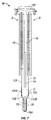
- FIG. 1 is a perspective view of a circuit module in accordance with a preferred embodiment of the present invention.
- FIG. 2 is an enlarged view of the area marked “C” in FIG. 1 .
- FIG. 3 is a depiction of one side of a flex circuit employed in a preferred embodiment of the present invention.
- FIG. 4 depicts another side of a flex circuit employed in a preferred embodiment of the present invention.
- FIG. 5 is a depiction of a portion of a conductive layer of a portion of a of flex circuit devised in accordance with the present invention.
- FIG. 6 depicts a cross-section of a portion of a module showing a portion of a flex circuit transiting about an end of a substrate in accordance with a preferred embodiment.
- FIG. 7 is a cross-sectional depiction of an exemplar module 10 according to a preferred embodiment.
- FIG. 8 is an enlarged depiction of the area marked “D” in FIG. 7 .
- FIG. 9 is an exemplar construction detail illustrating internal layer constructions for a flex circuitry in accordance with a preferred embodiment.
- FIG. 1 is a perspective view of a circuit module 10 devised in accordance with a preferred embodiment of the present invention.
- module 10 has two sides A and B and includes rigid substrate 14 having two opposing lateral sides 14 A and 14 B (shown in more detail in cross-section in FIG. 7 ) about which flex circuitry 12 is disposed.
- Substrate 14 is preferably comprised of thermally conductive material such as a metallic material with aluminum being a preferred choice for its thermal conductivity and ease of fabrication and cost while other thermally conductive materials may also be preferred such as thermally conductive plastics or carbon based materials.
- substrate 14 includes optional extension 16 .
- Flex circuitry 12 has two portions 12 A and a portion 12 B. Portions 12 A of flex circuit 12 are populated with ICs 18 along at least one of the two major surfaces of flex circuit 12 as shown in more detail in later Figs. Portion 12 B transits about end 16 A of substrate 14 .
- portions 12 A will be rigid while portion 12 B will be flexible and thus, flex circuit 12 may preferentially be devised from what is sometimes identified as “rigid-flex” with the flexible part corresponding to portion 12 B and the rigid part corresponding to portions 12 B of flex circuit 12 .
- rigid-flex is not required for the invention and a variety of flex circuitry constructions may be employed in preferred embodiments according to the principles disclosed herein.
- ICs 18 are memory devices in CSP packages.
- chip-scale or “CSP” shall refer to integrated circuitry of any function with an array package providing connection to one or more die through contacts (often embodied as “bumps” or “balls” for example) distributed across a major surface of the package or die.
- CSP does not refer to leaded devices that provide connection to an integrated circuit within the package through leads emergent from at least one side of the periphery of the package such as, for example, a TSOP.
- Embodiments of the present invention may be employed with leaded or CSP devices or other devices in both packaged and unpackaged forms but where the term CSP is used, the above definition for CSP should be adopted. Consequently, although CSP excludes leaded devices, references to CSP are to be broadly construed to include the large variety of array devices (and not to be limited to memory only) and whether die-sized or other size such as BGA and micro BGA as well as flip-chip. As those of skill will understand after appreciating this disclosure, some embodiments of the present invention may be devised to employ stacks of ICs each disposed where an IC 18 is indicated in the exemplar Figs.
- Multiple integrated circuit die may be included in a package depicted as a single IC 18 . While in this embodiment memory ICs are used to provide a memory expansion board or module, and various embodiments may include a variety of integrated circuits and other components. Such variety may include microprocessors, FPGA's, RF transceiver circuitry, digital logic, as a list of non-limiting examples, or other circuits or systems which may benefit from a high-density circuit board or module capability.
- module 10 may be employed with other ICs in addition to or other than ICs 18 such as, for example, an IC 19 which may be, for example, an advanced memory buffer (AMB) as employed in a fully-buffered DIMM instantiation on module 10 .
- AMB advanced memory buffer
- flex circuitry 12 exhibits 12 A parts or portions and a 12 B part or portion.
- portions 12 A of flex circuit 12 are populated with ICs 18 of module 10 while portion 12 B of flex circuitry 12 corresponds to a portion of flex circuit 12 that includes selected areas where flex circuitry 12 takes an arcuate path about substrate 14 , such as, for example, along substrate edge or end 16 A and about later shown flex support 14 FS.
- portions 12 A of flex circuit 12 may be alternatively identified as IC-mounting portions while portion 12 B of flex circuit 12 may be identified as a substrate transit portion of flex circuit 12 .
- Contacts 20 provide a connective facility for module 10 to an application environment and are depicted as being edge connector contacts so that module 10 may supplant a traditional DIMM comprised from, for example, FR4 board populated with ICs.
- flex circuit 12 preferably exhibits strain penetrations 13 and 15 with strain penetrations 15 being disposed proximal to the area about end 16 A of substrate 14 .
- portion 12 B of flex circuit 12 exhibits fewer layers than portions 12 A thus providing an enhanced ability for flex circuit 12 to transit about substrate 14 .
- FIG. 2 is an enlarged view of the area marked “C” in FIG. 1 .
- flex circuit 12 has portions 12 A and 12 B. Strain penetrations 15 are disposed in flex circuit 12 along its portion that transits the end portion 16 A of substrate 14 .
- Portion 12 B of flex circuit 12 that transits about end 16 A of substrate 14 contains circuit pathways that provide various connections from side A to side B of circuit module 10 .
- circuit module 10 exhibits connections from one side of the module to another side without the connections being required to pass through the substrate 14 .
- FIG. 3 is a depiction of side 8 of a flex circuit 12 in accordance with a preferred embodiment of the present invention.
- Flex circuit 12 may come in a variety of shapes including but not limited to square.
- Contact arrays such as array 11 are disposed beneath ICs 18 and IC 19 (shown in FIG. 4 ) and are comprised of array contacts 11 A.
- An exemplar contact array 11 is shown as is exemplar IC 18 to be mounted at contact array 11 as depicted.
- flex circuit 12 bears a plurality of module contacts allocated in this embodiment into two rows of module contacts 20 .
- flex circuit 12 FIG. 4
- side 8 depicted in FIG. 3 is presented at the outside of module 10 .
- the opposing side 9 of flex circuit 12 FIG. 4
- side 9 is closer to the substrate 14 about which flex circuit 12 is disposed than is side 8 .
- portions 12 A and 12 B are shown as being delineated from each other by dotted line 12 D.
- Line 12 D is shown for illustrative purposes.
- Contacts 20 are shown located near a central axis of flex circuit 12 but may be located near an edge of flex circuit 12 in embodiments that locate the circuitry on only one side of substrate 14 , for example. Such examples are shown in U.S. patent application Ser. No. 11/123,721 which has been incorporated by reference herein.
- flex circuit 12 is a multi-layer flex circuit having multiple conductive planes or layers from which are configured appropriate traces to implement the required connections of the module.
- the number of layers and their arrangement varies from portion 12 A to portion 12 B, however, in a preferred embodiment.
- Strain penetrations 15 are shown in FIG. 3 as are strain penetrations 13 in part of portion 12 B.
- FIG. 4 illustrates major side 9 of flex circuit 12 which is the side opposite that depicted in FIG. 3 .
- IC 19 an advanced memory buffer or AMB is disposed on side 9 of flex circuit 12 along with multiple iterations of ICs 18 .
- No contacts 20 are exhibited by this exemplar depiction of side 9 given that this side of flex circuit 12 will be disposed on the “inner” side of module 10 when flex circuit 12 is disposed about substrate 14 .
- FIG. 5 is a depiction of a portion of a metal layer 48 X of portion 12 B of flex circuit 12 devised in accordance with the present invention. As shown, metal layer 48 X exhibits strain penetrations 15 and 13 that pass through flex circuit 12 . For further strain relief, portions of metal layer 48 X of flex circuit 12 are patterned as exemplified by references 48 P.
- FIG. 6 depicts a cross-section of a portion of module 10 showing portion 12 B of flex circuit 12 transiting about end 16 A of substrate 14 .
- Adhesive 30 is shown that may, in some embodiments, be employed to affix together substrate 14 and flex circuit 12 in the area depicted as well as other portions of the module as those of skill be recognize.
- FIG. 7 is a cross-sectional depiction of an exemplar module 10 according to a preferred embodiment.
- module 10 includes ICs 18 and at least one IC 19 depicted with the profile of an AMB.
- Further embodiments that employ cutaway and window implementations of substrate 14 are disclosed in a variety of the patent applications incorporated by reference herein.
- module 10 may be populated with integrated circuits of a variety of functions and types including but not limited to memory, logic, graphics, microprocessors, FPGA, and communications, for example.
- Flex support 14 FS is shown as are portions 12 A and 12 B of flex circuit 12 .
- FIG. 8 is an enlarged depiction of the area marked “D” in FIG. 7 .
- flex circuitry 12 exhibits two portions 12 A and portion 12 B.
- FIG. 8 depicts an enlarged view of the area near end or edge 16 A of an exemplar module 10 . While a rounded configuration is shown, edge 16 A may take on other shapes devised to mate with various connectors or sockets. The form and function of various edge card connectors are well know in the art.
- flex 12 is wrapped around edge 16 A of substrate 14 and may be laminated or adhesively connected to substrate 14 with adhesive 30 . Flex circuit 12 may vary in thickness and is not strictly shown to scale.
- the depicted substrate 14 has a thickness such that when assembled with the flex 12 and adhesive 30 , the thickness measured between module contacts 20 falls in the range specified for the mating connector.
- flex circuit 12 is a rigid-flex circuit
- flex circuit 12 may be implemented with two rigid boards as implementations of preferably rigid portions 12 A of flex circuits 12 while portion 12 B may be a flexible circuit.
- Such a construction is shown in U.S. application Ser. No. 11/131,835, filed May 18, 2005 which application has been incorporated by reference herein.
- contacts 20 need not be on both sides of module 10 and may be exhibited on only one side in configurations.
- FIG. 9 is an exemplar construction detail illustrating internal layer constructions for flex circuit 12 in portions 12 A and 12 B.
- outer layers 40 a and 40 b are preferably solder masks, a construction well known in the industry. Those of skill will recognize that solder mask layers are not required to implement flex circuitry that may function as flex circuit 12 in the context of the invention.
- Layer 42 is a first conductive layer preferably comprised of copper while layer 44 is polyimide in a preferred embodiment. As shown, those layers that continue in portion 12 B of flex circuit 12 are seen on both sides of central polyimide layer 50 .
- Layer 46 is an adhesive while layer 48 is a second conductive layer which, like layer 42 , is preferably comprised of copper.
- Layer 52 is a third conductive layer preferably comprised of copper and layer 54 is a fourth conductive layer preferably comprised of copper.
- layer 48 is identified as 48 X to indicate the preferred cross-hatched nature of that layer in that portion 12 B of flex circuit 12 .
Abstract
Description
Claims (4)
Priority Applications (1)
| Application Number | Priority Date | Filing Date | Title |
|---|---|---|---|
| US11/331,969 US7616452B2 (en) | 2004-09-03 | 2006-01-13 | Flex circuit constructions for high capacity circuit module systems and methods |
Applications Claiming Priority (10)
| Application Number | Priority Date | Filing Date | Title |
|---|---|---|---|
| US10/934,027 US20060050492A1 (en) | 2004-09-03 | 2004-09-03 | Thin module system and method |
| US11/005,992 US7480152B2 (en) | 2004-09-03 | 2004-12-07 | Thin module system and method |
| US11/007,551 US7511968B2 (en) | 2004-09-03 | 2004-12-08 | Buffered thin module system and method |
| US11/068,688 US7324352B2 (en) | 2004-09-03 | 2005-03-01 | High capacity thin module system and method |
| US11/123,721 US20060053345A1 (en) | 2004-09-03 | 2005-05-06 | Thin module system and method |
| US11/131,835 US20060261449A1 (en) | 2005-05-18 | 2005-05-18 | Memory module system and method |
| US11/193,954 US20060049513A1 (en) | 2004-09-03 | 2005-07-29 | Thin module system and method with thermal management |
| PCT/US2005/028547 WO2006028643A2 (en) | 2004-09-03 | 2005-08-10 | Circuit module system and method |
| US11/231,418 US7443023B2 (en) | 2004-09-03 | 2005-09-21 | High capacity thin module system |
| US11/331,969 US7616452B2 (en) | 2004-09-03 | 2006-01-13 | Flex circuit constructions for high capacity circuit module systems and methods |
Related Parent Applications (9)
| Application Number | Title | Priority Date | Filing Date |
|---|---|---|---|
| US10/934,027 Continuation-In-Part US20060050492A1 (en) | 2004-09-03 | 2004-09-03 | Thin module system and method |
| US11/005,992 Continuation-In-Part US7480152B2 (en) | 2004-09-03 | 2004-12-07 | Thin module system and method |
| US11/007,551 Continuation-In-Part US7511968B2 (en) | 2004-09-03 | 2004-12-08 | Buffered thin module system and method |
| US11/068,688 Continuation-In-Part US7324352B2 (en) | 2004-09-03 | 2005-03-01 | High capacity thin module system and method |
| US11/123,721 Continuation-In-Part US20060053345A1 (en) | 2004-09-03 | 2005-05-06 | Thin module system and method |
| US11/131,835 Continuation-In-Part US20060261449A1 (en) | 2004-09-03 | 2005-05-18 | Memory module system and method |
| US11/193,954 Continuation-In-Part US20060049513A1 (en) | 2004-09-03 | 2005-07-29 | Thin module system and method with thermal management |
| PCT/US2005/028547 Continuation-In-Part WO2006028643A2 (en) | 2004-09-03 | 2005-08-10 | Circuit module system and method |
| US11/231,418 Continuation-In-Part US7443023B2 (en) | 2004-09-03 | 2005-09-21 | High capacity thin module system |
Related Child Applications (3)
| Application Number | Title | Priority Date | Filing Date |
|---|---|---|---|
| US11/005,992 Continuation-In-Part US7480152B2 (en) | 2004-09-03 | 2004-12-07 | Thin module system and method |
| US11/007,551 Continuation-In-Part US7511968B2 (en) | 2004-09-03 | 2004-12-08 | Buffered thin module system and method |
| US11/193,954 Continuation-In-Part US20060049513A1 (en) | 2004-09-03 | 2005-07-29 | Thin module system and method with thermal management |
Publications (2)
| Publication Number | Publication Date |
|---|---|
| US20060125067A1 US20060125067A1 (en) | 2006-06-15 |
| US7616452B2 true US7616452B2 (en) | 2009-11-10 |
Family
ID=46205830
Family Applications (1)
| Application Number | Title | Priority Date | Filing Date |
|---|---|---|---|
| US11/331,969 Active 2025-04-03 US7616452B2 (en) | 2004-09-03 | 2006-01-13 | Flex circuit constructions for high capacity circuit module systems and methods |
Country Status (1)
| Country | Link |
|---|---|
| US (1) | US7616452B2 (en) |
Cited By (16)
| Publication number | Priority date | Publication date | Assignee | Title |
|---|---|---|---|---|
| US20120235290A1 (en) * | 2009-10-07 | 2012-09-20 | Valeo Etudes Electroniques | Power module for an automobile |
| US20130314887A1 (en) * | 2012-05-25 | 2013-11-28 | Jin-san Jung | Slot-Mounted Printed Circuit Board Having Small Insertion Force |
| US8649820B2 (en) | 2011-11-07 | 2014-02-11 | Blackberry Limited | Universal integrated circuit card apparatus and related methods |
| USD701864S1 (en) * | 2012-04-23 | 2014-04-01 | Blackberry Limited | UICC apparatus |
| USD702240S1 (en) | 2012-04-13 | 2014-04-08 | Blackberry Limited | UICC apparatus |
| US8936199B2 (en) | 2012-04-13 | 2015-01-20 | Blackberry Limited | UICC apparatus and related methods |
| US8971045B1 (en) * | 2004-04-09 | 2015-03-03 | Netlist, Inc. | Module having at least one thermally conductive layer between printed circuit boards |
| US20160055365A1 (en) * | 2004-10-04 | 2016-02-25 | Synaptics Incorporated | Fingerprint sensing assemblies and methods of making |
| USD757666S1 (en) * | 2014-10-16 | 2016-05-31 | Japan Aviation Electronics Industry, Limited | Flexible printed circuit |
| USD784936S1 (en) * | 2014-05-28 | 2017-04-25 | Sumitomo Electric Industries, Ltd. | Flexible printed wiring board with device |
| USD785575S1 (en) * | 2014-05-28 | 2017-05-02 | Sumitomo Electric Industries, Ltd. | Flexible printed wiring board |
| US9721137B2 (en) | 2004-04-16 | 2017-08-01 | Synaptics Incorporated | Method and apparatus for fingerprint image reconstruction |
| US9972930B1 (en) * | 2017-01-16 | 2018-05-15 | Methode Electronics, Inc. | Transceiver module wit flex circuit |
| US11201441B2 (en) * | 2016-08-24 | 2021-12-14 | Harting Electric Gmbh & Co. Kg | Plug-in connector |
| US11449384B2 (en) | 2018-01-05 | 2022-09-20 | Yale University | Hardware-efficient fault-tolerant operations with superconducting circuits |
| US11635456B2 (en) * | 2016-02-12 | 2023-04-25 | Yale University | Techniques for control of quantum systems and related systems and methods |
Families Citing this family (23)
| Publication number | Priority date | Publication date | Assignee | Title |
|---|---|---|---|---|
| US7443023B2 (en) | 2004-09-03 | 2008-10-28 | Entorian Technologies, Lp | High capacity thin module system |
| US7579687B2 (en) * | 2004-09-03 | 2009-08-25 | Entorian Technologies, Lp | Circuit module turbulence enhancement systems and methods |
| US20060050492A1 (en) * | 2004-09-03 | 2006-03-09 | Staktek Group, L.P. | Thin module system and method |
| US7760513B2 (en) | 2004-09-03 | 2010-07-20 | Entorian Technologies Lp | Modified core for circuit module system and method |
| US7423885B2 (en) | 2004-09-03 | 2008-09-09 | Entorian Technologies, Lp | Die module system |
| US7446410B2 (en) * | 2004-09-03 | 2008-11-04 | Entorian Technologies, Lp | Circuit module with thermal casing systems |
| US7511968B2 (en) * | 2004-09-03 | 2009-03-31 | Entorian Technologies, Lp | Buffered thin module system and method |
| US20060053345A1 (en) * | 2004-09-03 | 2006-03-09 | Staktek Group L.P. | Thin module system and method |
| US7442050B1 (en) | 2005-08-29 | 2008-10-28 | Netlist, Inc. | Circuit card with flexible connection for memory module with heat spreader |
| US7619893B1 (en) | 2006-02-17 | 2009-11-17 | Netlist, Inc. | Heat spreader for electronic modules |
| US7429788B2 (en) * | 2006-03-08 | 2008-09-30 | Microelectronics Assembly Technologies, Inc. | Thin multichip flex-module |
| US7394149B2 (en) * | 2006-03-08 | 2008-07-01 | Microelectronics Assembly Technologies, Inc. | Thin multichip flex-module |
| US7520781B2 (en) * | 2006-03-08 | 2009-04-21 | Microelectronics Assembly Technologies | Thin multichip flex-module |
| US7393226B2 (en) * | 2006-03-08 | 2008-07-01 | Microelectronics Assembly Technologies, Inc. | Thin multichip flex-module |
| US8018723B1 (en) | 2008-04-30 | 2011-09-13 | Netlist, Inc. | Heat dissipation for electronic modules |
| US20100134982A1 (en) * | 2008-12-01 | 2010-06-03 | Meyer Iv George Anthony | Memory heat dissipating structure and memory device having the same |
| US9320130B2 (en) * | 2010-10-25 | 2016-04-19 | Korea Electric Terminal Co., Ltd. | Printed circuit board, and board block for vehicles using the same |
| CN102841643A (en) * | 2011-06-20 | 2012-12-26 | 鸿富锦精密工业(深圳)有限公司 | Adapting block device |
| US9468090B2 (en) | 2012-10-29 | 2016-10-11 | Cisco Technology, Inc. | Current redistribution in a printed circuit board |
| US9888283B2 (en) | 2013-03-13 | 2018-02-06 | Nagrastar Llc | Systems and methods for performing transport I/O |
| USD758372S1 (en) * | 2013-03-13 | 2016-06-07 | Nagrastar Llc | Smart card interface |
| USD864968S1 (en) | 2015-04-30 | 2019-10-29 | Echostar Technologies L.L.C. | Smart card interface |
| CN113301733A (en) * | 2021-04-29 | 2021-08-24 | 珠海新业电子科技有限公司 | Manufacturing method of soft and hard board combined structure |
Citations (114)
| Publication number | Priority date | Publication date | Assignee | Title |
|---|---|---|---|---|
| US3372310A (en) | 1965-04-30 | 1968-03-05 | Radiation Inc | Universal modular packages for integrated circuits |
| US3436604A (en) | 1966-04-25 | 1969-04-01 | Texas Instruments Inc | Complex integrated circuit array and method for fabricating same |
| US3582865A (en) | 1969-12-16 | 1971-06-01 | Ibm | Microcircuit module and connector |
| US3654394A (en) | 1969-07-08 | 1972-04-04 | Gordon Eng Co | Field effect transistor switch, particularly for multiplexing |
| US3704455A (en) | 1971-02-01 | 1972-11-28 | Alfred D Scarbrough | 3d-coaxial memory construction and method of making |
| US3718842A (en) | 1972-04-21 | 1973-02-27 | Texas Instruments Inc | Liquid crystal display mounting structure |
| US3727064A (en) | 1971-03-17 | 1973-04-10 | Monsanto Co | Opto-isolator devices and method for the fabrication thereof |
| US3746934A (en) | 1971-05-06 | 1973-07-17 | Siemens Ag | Stack arrangement of semiconductor chips |
| US3766439A (en) | 1972-01-12 | 1973-10-16 | Gen Electric | Electronic module using flexible printed circuit board with heat sink means |
| US3772776A (en) | 1969-12-03 | 1973-11-20 | Thomas & Betts Corp | Method of interconnecting memory plane boards |
| US4169642A (en) | 1976-09-16 | 1979-10-02 | E. I. Du Pont De Nemours And Company | Integrated circuit connector |
| US4288841A (en) | 1979-09-20 | 1981-09-08 | Bell Telephone Laboratories, Incorporated | Double cavity semiconductor chip carrier |
| US4342069A (en) | 1979-07-02 | 1982-07-27 | Mostek Corporation | Integrated circuit package |
| US4429349A (en) | 1980-09-30 | 1984-01-31 | Burroughs Corporation | Coil connector |
| US4437235A (en) | 1980-12-29 | 1984-03-20 | Honeywell Information Systems Inc. | Integrated circuit package |
| US4495546A (en) | 1981-05-18 | 1985-01-22 | Matsushita Electric Industrial Co., Ltd. | Hybrid integrated circuit component and printed circuit board mounting said component |
| US4513368A (en) | 1981-05-22 | 1985-04-23 | Data General Corporation | Digital data processing system having object-based logical memory addressing and self-structuring modular memory |
| US4547834A (en) | 1982-12-30 | 1985-10-15 | Thomson-Csf | Structure for assembling complex electronic circuits |
| US4567543A (en) | 1983-02-15 | 1986-01-28 | Motorola, Inc. | Double-sided flexible electronic circuit module |
| US4587596A (en) | 1984-04-09 | 1986-05-06 | Amp Incorporated | High density mother/daughter circuit board connector |
| US4645944A (en) | 1983-09-05 | 1987-02-24 | Matsushita Electric Industrial Co., Ltd. | MOS register for selecting among various data inputs |
| US4656605A (en) | 1983-09-02 | 1987-04-07 | Wang Laboratories, Inc. | Single in-line memory module |
| US4672421A (en) | 1984-04-02 | 1987-06-09 | Motorola, Inc. | Semiconductor packaging and method |
| US4682207A (en) | 1982-03-17 | 1987-07-21 | Fujitsu Limited | Semiconductor device including leadless packages and a base plate for mounting the leadless packages |
| US4696525A (en) | 1985-12-13 | 1987-09-29 | Amp Incorporated | Socket for stacking integrated circuit packages |
| US4709300A (en) | 1986-05-05 | 1987-11-24 | Itt Gallium Arsenide Technology Center, A Division Of Itt Corporation | Jumper for a semiconductor assembly |
| US4724611A (en) | 1985-08-23 | 1988-02-16 | Nec Corporation | Method for producing semiconductor module |
| US4727513A (en) | 1983-09-02 | 1988-02-23 | Wang Laboratories, Inc. | Signal in-line memory module |
| US4733461A (en) | 1984-12-28 | 1988-03-29 | Micro Co., Ltd. | Method of stacking printed circuit boards |
| US4739589A (en) | 1985-07-12 | 1988-04-26 | Wacker-Chemitronic Gesellschaft Fur Elektronik-Grundstoff Mbh | Process and apparatus for abrasive machining of a wafer-like workpiece |
| US4763188A (en) | 1986-08-08 | 1988-08-09 | Thomas Johnson | Packaging system for multiple semiconductor devices |
| US4771366A (en) | 1987-07-06 | 1988-09-13 | International Business Machines Corporation | Ceramic card assembly having enhanced power distribution and cooling |
| US4821007A (en) | 1987-02-06 | 1989-04-11 | Tektronix, Inc. | Strip line circuit component and method of manufacture |
| US4823234A (en) | 1985-08-16 | 1989-04-18 | Dai-Ichi Seiko Co., Ltd. | Semiconductor device and its manufacture |
| US4833568A (en) | 1988-01-29 | 1989-05-23 | Berhold G Mark | Three-dimensional circuit component assembly and method corresponding thereto |
| US4839717A (en) | 1986-12-19 | 1989-06-13 | Fairchild Semiconductor Corporation | Ceramic package for high frequency semiconductor devices |
| US4850892A (en) | 1985-12-16 | 1989-07-25 | Wang Laboratories, Inc. | Connecting apparatus for electrically connecting memory modules to a printed circuit board |
| US4862249A (en) | 1987-04-17 | 1989-08-29 | Xoc Devices, Inc. | Packaging system for stacking integrated circuits |
| US4911643A (en) | 1988-10-11 | 1990-03-27 | Beta Phase, Inc. | High density and high signal integrity connector |
| US4953060A (en) | 1989-05-05 | 1990-08-28 | Ncr Corporation | Stackable integrated circuit chip package with improved heat removal |
| US4956694A (en) | 1988-11-04 | 1990-09-11 | Dense-Pac Microsystems, Inc. | Integrated circuit chip stacking |
| US4972580A (en) | 1988-06-24 | 1990-11-27 | Kabushiki Kaisha Toshiba | Method for connecting electronic components with dummy patterns |
| US4982265A (en) | 1987-06-24 | 1991-01-01 | Hitachi, Ltd. | Semiconductor integrated circuit device and method of manufacturing the same |
| US4983533A (en) | 1987-10-28 | 1991-01-08 | Irvine Sensors Corporation | High-density electronic modules - process and product |
| US4985703A (en) | 1988-02-03 | 1991-01-15 | Nec Corporation | Analog multiplexer |
| US4992849A (en) | 1989-02-15 | 1991-02-12 | Micron Technology, Inc. | Directly bonded board multiple integrated circuit module |
| US4992850A (en) | 1989-02-15 | 1991-02-12 | Micron Technology, Inc. | Directly bonded simm module |
| US5014115A (en) | 1987-11-16 | 1991-05-07 | Motorola, Inc. | Coplanar waveguide semiconductor package |
| US5014161A (en) | 1985-07-22 | 1991-05-07 | Digital Equipment Corporation | System for detachably mounting semiconductors on conductor substrate |
| US5016138A (en) | 1987-10-27 | 1991-05-14 | Woodman John K | Three dimensional integrated circuit package |
| US5025306A (en) | 1988-08-09 | 1991-06-18 | Texas Instruments Incorporated | Assembly of semiconductor chips |
| US5034350A (en) | 1987-09-23 | 1991-07-23 | Sgs Thomson Microelectronics S.R.L. | Semiconductor device package with dies mounted on both sides of the central pad of a metal frame |
| US5041015A (en) | 1990-03-30 | 1991-08-20 | Cal Flex, Inc. | Electrical jumper assembly |
| US5053853A (en) | 1990-05-08 | 1991-10-01 | International Business Machines Corporation | Modular electronic packaging system |
| US5065277A (en) | 1990-07-13 | 1991-11-12 | Sun Microsystems, Inc. | Three dimensional packaging arrangement for computer systems and the like |
| US5099393A (en) | 1991-03-25 | 1992-03-24 | International Business Machines Corporation | Electronic package for high density applications |
| US5104820A (en) | 1989-07-07 | 1992-04-14 | Irvine Sensors Corporation | Method of fabricating electronic circuitry unit containing stacked IC layers having lead rerouting |
| US5109318A (en) | 1990-05-07 | 1992-04-28 | International Business Machines Corporation | Pluggable electronic circuit package assembly with snap together heat sink housing |
| US5117282A (en) | 1990-10-29 | 1992-05-26 | Harris Corporation | Stacked configuration for integrated circuit devices |
| US5119269A (en) | 1989-08-23 | 1992-06-02 | Seiko Epson Corporation | Semiconductor with a battery unit |
| US5138523A (en) | 1991-10-18 | 1992-08-11 | International Business Machines Corporation | Digitizer tablet having cooling apparatus with base and integrated heat sink |
| US5138434A (en) | 1991-01-22 | 1992-08-11 | Micron Technology, Inc. | Packaging for semiconductor logic devices |
| US5138430A (en) | 1991-06-06 | 1992-08-11 | International Business Machines Corporation | High performance versatile thermally enhanced IC chip mounting |
| US5140405A (en) | 1990-08-30 | 1992-08-18 | Micron Technology, Inc. | Semiconductor assembly utilizing elastomeric single axis conductive interconnect |
| US5159535A (en) | 1987-03-11 | 1992-10-27 | International Business Machines Corporation | Method and apparatus for mounting a flexible film semiconductor chip carrier on a circuitized substrate |
| US5173840A (en) | 1990-05-07 | 1992-12-22 | Mitsubishi Denki Kabushiki Kaisha | Molded ic card |
| US5191404A (en) | 1989-12-20 | 1993-03-02 | Digital Equipment Corporation | High density memory array packaging |
| US5208729A (en) | 1992-02-14 | 1993-05-04 | International Business Machines Corporation | Multi-chip module |
| US5214845A (en) | 1992-05-11 | 1993-06-01 | Micron Technology, Inc. | Method for producing high speed integrated circuits |
| US5219377A (en) | 1992-01-17 | 1993-06-15 | Texas Instruments Incorporated | High temperature co-fired ceramic integrated phased array package |
| US5222014A (en) | 1992-03-02 | 1993-06-22 | Motorola, Inc. | Three-dimensional multi-chip pad array carrier |
| US5224023A (en) * | 1992-02-10 | 1993-06-29 | Smith Gary W | Foldable electronic assembly module |
| US5229917A (en) | 1992-07-24 | 1993-07-20 | The United States Of America As Represented By The Secretary Of The Air Force | VLSI integration into a 3-D WSI dual composite module |
| US5229916A (en) | 1992-03-04 | 1993-07-20 | International Business Machines Corporation | Chip edge interconnect overlay element |
| US5239198A (en) | 1989-09-06 | 1993-08-24 | Motorola, Inc. | Overmolded semiconductor device having solder ball and edge lead connective structure |
| US5241454A (en) | 1992-01-22 | 1993-08-31 | International Business Machines Corporation | Mutlilayered flexible circuit package |
| US5241456A (en) | 1990-07-02 | 1993-08-31 | General Electric Company | Compact high density interconnect structure |
| US5247423A (en) | 1992-05-26 | 1993-09-21 | Motorola, Inc. | Stacking three dimensional leadless multi-chip module and method for making the same |
| US5252857A (en) | 1991-08-05 | 1993-10-12 | International Business Machines Corporation | Stacked DCA memory chips |
| US5259770A (en) | 1992-03-19 | 1993-11-09 | Amp Incorporated | Impedance controlled elastomeric connector |
| US5261068A (en) | 1990-05-25 | 1993-11-09 | Dell Usa L.P. | Dual path memory retrieval system for an interleaved dynamic RAM memory unit |
| US5268815A (en) | 1992-02-14 | 1993-12-07 | International Business Machines Corporation | High density, high performance memory circuit package |
| US5276418A (en) | 1988-11-16 | 1994-01-04 | Motorola, Inc. | Flexible substrate electronic assembly |
| US5281852A (en) | 1991-12-10 | 1994-01-25 | Normington Peter J C | Semiconductor device including stacked die |
| US5285398A (en) | 1992-05-15 | 1994-02-08 | Mobila Technology Inc. | Flexible wearable computer |
| US5289062A (en) | 1991-03-18 | 1994-02-22 | Quality Semiconductor, Inc. | Fast transmission gate switch |
| US5309986A (en) | 1992-11-30 | 1994-05-10 | Satomi Itoh | Heat pipe |
| US5313097A (en) | 1992-11-16 | 1994-05-17 | International Business Machines, Corp. | High density memory module |
| US5343366A (en) | 1992-06-24 | 1994-08-30 | International Business Machines Corporation | Packages for stacked integrated circuit chip cubes |
| US5347428A (en) | 1992-12-03 | 1994-09-13 | Irvine Sensors Corporation | Module comprising IC memory stack dedicated to and structurally combined with an IC microprocessor chip |
| US5362656A (en) | 1992-12-02 | 1994-11-08 | Intel Corporation | Method of making an electronic assembly having a flexible circuit wrapped around a substrate |
| US5386341A (en) | 1993-11-01 | 1995-01-31 | Motorola, Inc. | Flexible substrate folded in a U-shape with a rigidizer plate located in the notch of the U-shape |
| US5394300A (en) | 1992-09-04 | 1995-02-28 | Mitsubishi Denki Kabushiki Kaisha | Thin multilayered IC memory card |
| US5397916A (en) | 1991-12-10 | 1995-03-14 | Normington; Peter J. C. | Semiconductor device including stacked die |
| US5400003A (en) | 1992-08-19 | 1995-03-21 | Micron Technology, Inc. | Inherently impedance matched integrated circuit module |
| US5428190A (en) | 1993-07-02 | 1995-06-27 | Sheldahl, Inc. | Rigid-flex board with anisotropic interconnect and method of manufacture |
| US5438224A (en) | 1992-04-23 | 1995-08-01 | Motorola, Inc. | Integrated circuit package having a face-to-face IC chip arrangement |
| US5445869A (en) * | 1993-01-21 | 1995-08-29 | Matsushita Electric Industrial Co., Ltd. | Composite flexible substrate |
| US5448511A (en) | 1994-06-01 | 1995-09-05 | Storage Technology Corporation | Memory stack with an integrated interconnect and mounting structure |
| US5463742A (en) | 1993-03-05 | 1995-10-31 | Hitachi Computer Products (America), Inc. | Personal processor module and docking station for use therewith |
| US5731633A (en) * | 1992-09-16 | 1998-03-24 | Gary W. Hamilton | Thin multichip module |
| US5949657A (en) * | 1997-12-01 | 1999-09-07 | Karabatsos; Chris | Bottom or top jumpered foldable electronic assembly |
| US6021048A (en) * | 1998-02-17 | 2000-02-01 | Smith; Gary W. | High speed memory module |
| US20020038405A1 (en) * | 1998-09-30 | 2002-03-28 | Michael W. Leddige | Method and apparatus for implementing multiple memory buses on a memory module |
| US6392305B1 (en) * | 1999-03-31 | 2002-05-21 | Chih-Kung Huang | Chip scale package of semiconductor |
| US20020125039A1 (en) * | 1999-05-25 | 2002-09-12 | Marketkar Nandu J. | Electromagnetic coupler alignment |
| US20030116835A1 (en) * | 1999-02-26 | 2003-06-26 | Hitachi, Ltd. | Memory-module and a method of manufacturing the same |
| US20030234443A1 (en) * | 2001-10-26 | 2003-12-25 | Staktek Group, L.P. | Low profile stacking system and method |
| US6762942B1 (en) * | 2002-09-05 | 2004-07-13 | Gary W. Smith | Break away, high speed, folded, jumperless electronic assembly |
| US20040236877A1 (en) * | 1997-12-17 | 2004-11-25 | Lee A. Burton | Switch/network adapter port incorporating shared memory resources selectively accessible by a direct execution logic element and one or more dense logic devices in a fully buffered dual in-line memory module format (FB-DIMM) |
| US20050105350A1 (en) * | 2003-11-13 | 2005-05-19 | David Zimmerman | Memory channel test fixture and method |
| US20050138267A1 (en) * | 2003-12-23 | 2005-06-23 | Bains Kuljit S. | Integral memory buffer and serial presence detect capability for fully-buffered memory modules |
| US7446410B2 (en) * | 2004-09-03 | 2008-11-04 | Entorian Technologies, Lp | Circuit module with thermal casing systems |
| US7480152B2 (en) * | 2004-09-03 | 2009-01-20 | Entorian Technologies, Lp | Thin module system and method |
Family Cites Families (55)
| Publication number | Priority date | Publication date | Assignee | Title |
|---|---|---|---|---|
| US5831828A (en) * | 1993-06-03 | 1998-11-03 | International Business Machines Corporation | Flexible circuit board and common heat spreader assembly |
| US5471367A (en) * | 1994-03-15 | 1995-11-28 | Composite Optics, Inc. | Composite structure for heat transfer and radiation |
| TW344043B (en) * | 1994-10-21 | 1998-11-01 | Hitachi Ltd | Liquid crystal display device with reduced frame portion surrounding display area |
| US5513135A (en) * | 1994-12-02 | 1996-04-30 | International Business Machines Corporation | Synchronous memory packaged in single/dual in-line memory module and method of fabrication |
| US5534356A (en) * | 1995-04-26 | 1996-07-09 | Olin Corporation | Anodized aluminum substrate having increased breakdown voltage |
| US5818699A (en) * | 1995-07-05 | 1998-10-06 | Kabushiki Kaisha Toshiba | Multi-chip module and production method thereof |
| JPH0992937A (en) * | 1995-09-25 | 1997-04-04 | Mitsubishi Electric Corp | Printed wiring board |
| US5999405A (en) * | 1997-05-05 | 1999-12-07 | Gateway 2000, Inc. | PCB module support system |
| US6061245A (en) * | 1998-01-22 | 2000-05-09 | International Business Machines Corporation | Free standing, three dimensional, multi-chip, carrier package with air flow baffle |
| US6307751B1 (en) * | 1998-06-01 | 2001-10-23 | Wearlogic, Inc. | Flexible circuit assembly |
| JP2000174399A (en) * | 1998-12-01 | 2000-06-23 | Nhk Spring Co Ltd | Stereoscopic wiring board, its manufacture and insulating material for board |
| US6324071B2 (en) * | 1999-01-14 | 2001-11-27 | Micron Technology, Inc. | Stacked printed circuit board memory module |
| US6356958B1 (en) * | 1999-02-08 | 2002-03-12 | Mou-Shiung Lin | Integrated circuit module has common function known good integrated circuit die with multiple selectable functions |
| US6025992A (en) * | 1999-02-11 | 2000-02-15 | International Business Machines Corp. | Integrated heat exchanger for memory module |
| US7122889B2 (en) * | 2000-05-03 | 2006-10-17 | Rambus, Inc. | Semiconductor module |
| US6545875B1 (en) * | 2000-05-10 | 2003-04-08 | Rambus, Inc. | Multiple channel modules and bus systems using same |
| US6382309B1 (en) * | 2000-05-16 | 2002-05-07 | Swales Aerospace | Loop heat pipe incorporating an evaporator having a wick that is liquid superheat tolerant and is resistant to back-conduction |
| US6607937B1 (en) * | 2000-08-23 | 2003-08-19 | Micron Technology, Inc. | Stacked microelectronic dies and methods for stacking microelectronic dies |
| US6390837B1 (en) * | 2000-12-20 | 2002-05-21 | Hon Hai Precision Ind. Co., Ltd. | Card edge connector with safety ejector |
| US20020138159A1 (en) * | 2001-03-26 | 2002-09-26 | Atkinson Lee W. | Temperature responsive power supply to minimize power consumption of digital logic without reducing system performance |
| JP2003031885A (en) * | 2001-07-19 | 2003-01-31 | Toshiba Corp | Semiconductor laser device |
| US6897565B2 (en) * | 2001-10-09 | 2005-05-24 | Tessera, Inc. | Stacked packages |
| US6576992B1 (en) * | 2001-10-26 | 2003-06-10 | Staktek Group L.P. | Chip scale stacking system and method |
| US7053478B2 (en) * | 2001-10-26 | 2006-05-30 | Staktek Group L.P. | Pitch change and chip scale stacking system |
| US6842585B2 (en) * | 2002-04-18 | 2005-01-11 | Olympus Optical Co., Ltd. | Camera |
| DE10229712B4 (en) * | 2002-07-02 | 2009-06-25 | Jenoptik Laserdiode Gmbh | Semiconductor module |
| JP4159415B2 (en) * | 2002-08-23 | 2008-10-01 | エルピーダメモリ株式会社 | Memory module and memory system |
| TWI229253B (en) * | 2003-01-08 | 2005-03-11 | Ma Lab Inc | Structural improvement for removable cooler |
| US7164197B2 (en) * | 2003-06-19 | 2007-01-16 | 3M Innovative Properties Company | Dielectric composite material |
| JP3834023B2 (en) * | 2003-08-19 | 2006-10-18 | 株式会社東芝 | LSI package with interface module and heat sink used therefor |
| US7542304B2 (en) * | 2003-09-15 | 2009-06-02 | Entorian Technologies, Lp | Memory expansion and integrated circuit stacking system and method |
| US6888719B1 (en) * | 2003-10-16 | 2005-05-03 | Micron Technology, Inc. | Methods and apparatuses for transferring heat from microelectronic device modules |
| US7291795B2 (en) * | 2004-04-01 | 2007-11-06 | Arie Maharshak | Flexible printed circuits with many tiny holes |
| US7254036B2 (en) * | 2004-04-09 | 2007-08-07 | Netlist, Inc. | High density memory module using stacked printed circuit boards |
| US7157646B2 (en) * | 2004-07-02 | 2007-01-02 | Endicott Interconnect Technologies, Inc. | Circuitized substrate with split conductive layer, method of making same, electrical assembly utilizing same, and information handling system utilizing same |
| US7539800B2 (en) * | 2004-07-30 | 2009-05-26 | International Business Machines Corporation | System, method and storage medium for providing segment level sparing |
| US7235880B2 (en) * | 2004-09-01 | 2007-06-26 | Intel Corporation | IC package with power and signal lines on opposing sides |
| US20060048385A1 (en) * | 2004-09-03 | 2006-03-09 | Staktek Group L.P. | Minimized profile circuit module systems and methods |
| US7606049B2 (en) * | 2004-09-03 | 2009-10-20 | Entorian Technologies, Lp | Module thermal management system and method |
| US7289327B2 (en) * | 2006-02-27 | 2007-10-30 | Stakick Group L.P. | Active cooling methods and apparatus for modules |
| US7511968B2 (en) * | 2004-09-03 | 2009-03-31 | Entorian Technologies, Lp | Buffered thin module system and method |
| US7542297B2 (en) * | 2004-09-03 | 2009-06-02 | Entorian Technologies, Lp | Optimized mounting area circuit module system and method |
| US7468893B2 (en) * | 2004-09-03 | 2008-12-23 | Entorian Technologies, Lp | Thin module system and method |
| US7443023B2 (en) * | 2004-09-03 | 2008-10-28 | Entorian Technologies, Lp | High capacity thin module system |
| US7324352B2 (en) * | 2004-09-03 | 2008-01-29 | Staktek Group L.P. | High capacity thin module system and method |
| US20060049513A1 (en) * | 2004-09-03 | 2006-03-09 | Staktek Group L.P. | Thin module system and method with thermal management |
| US7106595B2 (en) * | 2004-09-15 | 2006-09-12 | International Business Machines Corporation | Apparatus including a thermal bus on a circuit board for cooling components on a daughter card releasably attached to the circuit board |
| US7187552B1 (en) * | 2005-03-04 | 2007-03-06 | Sun Microsystems, Inc. | Self-installing heat sink |
| US7520781B2 (en) * | 2006-03-08 | 2009-04-21 | Microelectronics Assembly Technologies | Thin multichip flex-module |
| US20070211711A1 (en) * | 2006-03-08 | 2007-09-13 | Clayton James E | Thin multichip flex-module |
| US7429788B2 (en) * | 2006-03-08 | 2008-09-30 | Microelectronics Assembly Technologies, Inc. | Thin multichip flex-module |
| US7393226B2 (en) * | 2006-03-08 | 2008-07-01 | Microelectronics Assembly Technologies, Inc. | Thin multichip flex-module |
| US7787254B2 (en) * | 2006-03-08 | 2010-08-31 | Microelectronics Assembly Technologies, Inc. | Thin multichip flex-module |
| US7394149B2 (en) * | 2006-03-08 | 2008-07-01 | Microelectronics Assembly Technologies, Inc. | Thin multichip flex-module |
| US20080192428A1 (en) * | 2007-02-08 | 2008-08-14 | Clayton James E | Thermal management system for computers |
-
2006
- 2006-01-13 US US11/331,969 patent/US7616452B2/en active Active
Patent Citations (117)
| Publication number | Priority date | Publication date | Assignee | Title |
|---|---|---|---|---|
| US3372310A (en) | 1965-04-30 | 1968-03-05 | Radiation Inc | Universal modular packages for integrated circuits |
| US3436604A (en) | 1966-04-25 | 1969-04-01 | Texas Instruments Inc | Complex integrated circuit array and method for fabricating same |
| US3654394A (en) | 1969-07-08 | 1972-04-04 | Gordon Eng Co | Field effect transistor switch, particularly for multiplexing |
| US3772776A (en) | 1969-12-03 | 1973-11-20 | Thomas & Betts Corp | Method of interconnecting memory plane boards |
| US3582865A (en) | 1969-12-16 | 1971-06-01 | Ibm | Microcircuit module and connector |
| US3704455A (en) | 1971-02-01 | 1972-11-28 | Alfred D Scarbrough | 3d-coaxial memory construction and method of making |
| US3727064A (en) | 1971-03-17 | 1973-04-10 | Monsanto Co | Opto-isolator devices and method for the fabrication thereof |
| US3746934A (en) | 1971-05-06 | 1973-07-17 | Siemens Ag | Stack arrangement of semiconductor chips |
| US3766439A (en) | 1972-01-12 | 1973-10-16 | Gen Electric | Electronic module using flexible printed circuit board with heat sink means |
| US3718842A (en) | 1972-04-21 | 1973-02-27 | Texas Instruments Inc | Liquid crystal display mounting structure |
| US4169642A (en) | 1976-09-16 | 1979-10-02 | E. I. Du Pont De Nemours And Company | Integrated circuit connector |
| US4342069A (en) | 1979-07-02 | 1982-07-27 | Mostek Corporation | Integrated circuit package |
| US4288841A (en) | 1979-09-20 | 1981-09-08 | Bell Telephone Laboratories, Incorporated | Double cavity semiconductor chip carrier |
| US4429349A (en) | 1980-09-30 | 1984-01-31 | Burroughs Corporation | Coil connector |
| US4437235A (en) | 1980-12-29 | 1984-03-20 | Honeywell Information Systems Inc. | Integrated circuit package |
| US4495546A (en) | 1981-05-18 | 1985-01-22 | Matsushita Electric Industrial Co., Ltd. | Hybrid integrated circuit component and printed circuit board mounting said component |
| US4513368A (en) | 1981-05-22 | 1985-04-23 | Data General Corporation | Digital data processing system having object-based logical memory addressing and self-structuring modular memory |
| US4682207A (en) | 1982-03-17 | 1987-07-21 | Fujitsu Limited | Semiconductor device including leadless packages and a base plate for mounting the leadless packages |
| US4547834A (en) | 1982-12-30 | 1985-10-15 | Thomson-Csf | Structure for assembling complex electronic circuits |
| US4567543A (en) | 1983-02-15 | 1986-01-28 | Motorola, Inc. | Double-sided flexible electronic circuit module |
| US4656605A (en) | 1983-09-02 | 1987-04-07 | Wang Laboratories, Inc. | Single in-line memory module |
| US4727513A (en) | 1983-09-02 | 1988-02-23 | Wang Laboratories, Inc. | Signal in-line memory module |
| US4645944A (en) | 1983-09-05 | 1987-02-24 | Matsushita Electric Industrial Co., Ltd. | MOS register for selecting among various data inputs |
| US4672421A (en) | 1984-04-02 | 1987-06-09 | Motorola, Inc. | Semiconductor packaging and method |
| US4587596A (en) | 1984-04-09 | 1986-05-06 | Amp Incorporated | High density mother/daughter circuit board connector |
| US4733461A (en) | 1984-12-28 | 1988-03-29 | Micro Co., Ltd. | Method of stacking printed circuit boards |
| US4739589A (en) | 1985-07-12 | 1988-04-26 | Wacker-Chemitronic Gesellschaft Fur Elektronik-Grundstoff Mbh | Process and apparatus for abrasive machining of a wafer-like workpiece |
| US5014161A (en) | 1985-07-22 | 1991-05-07 | Digital Equipment Corporation | System for detachably mounting semiconductors on conductor substrate |
| US4823234A (en) | 1985-08-16 | 1989-04-18 | Dai-Ichi Seiko Co., Ltd. | Semiconductor device and its manufacture |
| US4724611A (en) | 1985-08-23 | 1988-02-16 | Nec Corporation | Method for producing semiconductor module |
| US4696525A (en) | 1985-12-13 | 1987-09-29 | Amp Incorporated | Socket for stacking integrated circuit packages |
| US4850892A (en) | 1985-12-16 | 1989-07-25 | Wang Laboratories, Inc. | Connecting apparatus for electrically connecting memory modules to a printed circuit board |
| US4709300A (en) | 1986-05-05 | 1987-11-24 | Itt Gallium Arsenide Technology Center, A Division Of Itt Corporation | Jumper for a semiconductor assembly |
| US4763188A (en) | 1986-08-08 | 1988-08-09 | Thomas Johnson | Packaging system for multiple semiconductor devices |
| US4839717A (en) | 1986-12-19 | 1989-06-13 | Fairchild Semiconductor Corporation | Ceramic package for high frequency semiconductor devices |
| US4821007A (en) | 1987-02-06 | 1989-04-11 | Tektronix, Inc. | Strip line circuit component and method of manufacture |
| US5159535A (en) | 1987-03-11 | 1992-10-27 | International Business Machines Corporation | Method and apparatus for mounting a flexible film semiconductor chip carrier on a circuitized substrate |
| US4862249A (en) | 1987-04-17 | 1989-08-29 | Xoc Devices, Inc. | Packaging system for stacking integrated circuits |
| US4982265A (en) | 1987-06-24 | 1991-01-01 | Hitachi, Ltd. | Semiconductor integrated circuit device and method of manufacturing the same |
| US4771366A (en) | 1987-07-06 | 1988-09-13 | International Business Machines Corporation | Ceramic card assembly having enhanced power distribution and cooling |
| US5034350A (en) | 1987-09-23 | 1991-07-23 | Sgs Thomson Microelectronics S.R.L. | Semiconductor device package with dies mounted on both sides of the central pad of a metal frame |
| US5016138A (en) | 1987-10-27 | 1991-05-14 | Woodman John K | Three dimensional integrated circuit package |
| US4983533A (en) | 1987-10-28 | 1991-01-08 | Irvine Sensors Corporation | High-density electronic modules - process and product |
| US5014115A (en) | 1987-11-16 | 1991-05-07 | Motorola, Inc. | Coplanar waveguide semiconductor package |
| US4833568A (en) | 1988-01-29 | 1989-05-23 | Berhold G Mark | Three-dimensional circuit component assembly and method corresponding thereto |
| US4985703A (en) | 1988-02-03 | 1991-01-15 | Nec Corporation | Analog multiplexer |
| US4972580A (en) | 1988-06-24 | 1990-11-27 | Kabushiki Kaisha Toshiba | Method for connecting electronic components with dummy patterns |
| US5025306A (en) | 1988-08-09 | 1991-06-18 | Texas Instruments Incorporated | Assembly of semiconductor chips |
| US4911643A (en) | 1988-10-11 | 1990-03-27 | Beta Phase, Inc. | High density and high signal integrity connector |
| US4956694A (en) | 1988-11-04 | 1990-09-11 | Dense-Pac Microsystems, Inc. | Integrated circuit chip stacking |
| US5276418A (en) | 1988-11-16 | 1994-01-04 | Motorola, Inc. | Flexible substrate electronic assembly |
| US4992850A (en) | 1989-02-15 | 1991-02-12 | Micron Technology, Inc. | Directly bonded simm module |
| US4992849A (en) | 1989-02-15 | 1991-02-12 | Micron Technology, Inc. | Directly bonded board multiple integrated circuit module |
| US4953060A (en) | 1989-05-05 | 1990-08-28 | Ncr Corporation | Stackable integrated circuit chip package with improved heat removal |
| US5104820A (en) | 1989-07-07 | 1992-04-14 | Irvine Sensors Corporation | Method of fabricating electronic circuitry unit containing stacked IC layers having lead rerouting |
| US5119269A (en) | 1989-08-23 | 1992-06-02 | Seiko Epson Corporation | Semiconductor with a battery unit |
| US5239198A (en) | 1989-09-06 | 1993-08-24 | Motorola, Inc. | Overmolded semiconductor device having solder ball and edge lead connective structure |
| US5191404A (en) | 1989-12-20 | 1993-03-02 | Digital Equipment Corporation | High density memory array packaging |
| US5041015A (en) | 1990-03-30 | 1991-08-20 | Cal Flex, Inc. | Electrical jumper assembly |
| US5109318A (en) | 1990-05-07 | 1992-04-28 | International Business Machines Corporation | Pluggable electronic circuit package assembly with snap together heat sink housing |
| US5173840A (en) | 1990-05-07 | 1992-12-22 | Mitsubishi Denki Kabushiki Kaisha | Molded ic card |
| US5053853A (en) | 1990-05-08 | 1991-10-01 | International Business Machines Corporation | Modular electronic packaging system |
| US5261068A (en) | 1990-05-25 | 1993-11-09 | Dell Usa L.P. | Dual path memory retrieval system for an interleaved dynamic RAM memory unit |
| US5241456A (en) | 1990-07-02 | 1993-08-31 | General Electric Company | Compact high density interconnect structure |
| US5065277A (en) | 1990-07-13 | 1991-11-12 | Sun Microsystems, Inc. | Three dimensional packaging arrangement for computer systems and the like |
| US5140405A (en) | 1990-08-30 | 1992-08-18 | Micron Technology, Inc. | Semiconductor assembly utilizing elastomeric single axis conductive interconnect |
| US5117282A (en) | 1990-10-29 | 1992-05-26 | Harris Corporation | Stacked configuration for integrated circuit devices |
| US5138434A (en) | 1991-01-22 | 1992-08-11 | Micron Technology, Inc. | Packaging for semiconductor logic devices |
| US5289062A (en) | 1991-03-18 | 1994-02-22 | Quality Semiconductor, Inc. | Fast transmission gate switch |
| US5099393A (en) | 1991-03-25 | 1992-03-24 | International Business Machines Corporation | Electronic package for high density applications |
| US5138430A (en) | 1991-06-06 | 1992-08-11 | International Business Machines Corporation | High performance versatile thermally enhanced IC chip mounting |
| US5252857A (en) | 1991-08-05 | 1993-10-12 | International Business Machines Corporation | Stacked DCA memory chips |
| US5138523A (en) | 1991-10-18 | 1992-08-11 | International Business Machines Corporation | Digitizer tablet having cooling apparatus with base and integrated heat sink |
| US5397916A (en) | 1991-12-10 | 1995-03-14 | Normington; Peter J. C. | Semiconductor device including stacked die |
| US5281852A (en) | 1991-12-10 | 1994-01-25 | Normington Peter J C | Semiconductor device including stacked die |
| US5219377A (en) | 1992-01-17 | 1993-06-15 | Texas Instruments Incorporated | High temperature co-fired ceramic integrated phased array package |
| US5241454A (en) | 1992-01-22 | 1993-08-31 | International Business Machines Corporation | Mutlilayered flexible circuit package |
| US5224023A (en) * | 1992-02-10 | 1993-06-29 | Smith Gary W | Foldable electronic assembly module |
| US5268815A (en) | 1992-02-14 | 1993-12-07 | International Business Machines Corporation | High density, high performance memory circuit package |
| US5208729A (en) | 1992-02-14 | 1993-05-04 | International Business Machines Corporation | Multi-chip module |
| US5222014A (en) | 1992-03-02 | 1993-06-22 | Motorola, Inc. | Three-dimensional multi-chip pad array carrier |
| US5229916A (en) | 1992-03-04 | 1993-07-20 | International Business Machines Corporation | Chip edge interconnect overlay element |
| US5259770A (en) | 1992-03-19 | 1993-11-09 | Amp Incorporated | Impedance controlled elastomeric connector |
| US5438224A (en) | 1992-04-23 | 1995-08-01 | Motorola, Inc. | Integrated circuit package having a face-to-face IC chip arrangement |
| US5214845A (en) | 1992-05-11 | 1993-06-01 | Micron Technology, Inc. | Method for producing high speed integrated circuits |
| US5285398A (en) | 1992-05-15 | 1994-02-08 | Mobila Technology Inc. | Flexible wearable computer |
| US5247423A (en) | 1992-05-26 | 1993-09-21 | Motorola, Inc. | Stacking three dimensional leadless multi-chip module and method for making the same |
| US5343366A (en) | 1992-06-24 | 1994-08-30 | International Business Machines Corporation | Packages for stacked integrated circuit chip cubes |
| US5229917A (en) | 1992-07-24 | 1993-07-20 | The United States Of America As Represented By The Secretary Of The Air Force | VLSI integration into a 3-D WSI dual composite module |
| US5400003A (en) | 1992-08-19 | 1995-03-21 | Micron Technology, Inc. | Inherently impedance matched integrated circuit module |
| US5394300A (en) | 1992-09-04 | 1995-02-28 | Mitsubishi Denki Kabushiki Kaisha | Thin multilayered IC memory card |
| US6232659B1 (en) * | 1992-09-16 | 2001-05-15 | James E. Clayton | Thin multichip module |
| US6091145A (en) * | 1992-09-16 | 2000-07-18 | Clayton; James E. | Thin multichip module including a connector frame socket |
| US5731633A (en) * | 1992-09-16 | 1998-03-24 | Gary W. Hamilton | Thin multichip module |
| US5313097A (en) | 1992-11-16 | 1994-05-17 | International Business Machines, Corp. | High density memory module |
| US5309986A (en) | 1992-11-30 | 1994-05-10 | Satomi Itoh | Heat pipe |
| US5362656A (en) | 1992-12-02 | 1994-11-08 | Intel Corporation | Method of making an electronic assembly having a flexible circuit wrapped around a substrate |
| US5375041A (en) | 1992-12-02 | 1994-12-20 | Intel Corporation | Ra-tab array bump tab tape based I.C. package |
| US5347428A (en) | 1992-12-03 | 1994-09-13 | Irvine Sensors Corporation | Module comprising IC memory stack dedicated to and structurally combined with an IC microprocessor chip |
| US5445869A (en) * | 1993-01-21 | 1995-08-29 | Matsushita Electric Industrial Co., Ltd. | Composite flexible substrate |
| US5463742A (en) | 1993-03-05 | 1995-10-31 | Hitachi Computer Products (America), Inc. | Personal processor module and docking station for use therewith |
| US5428190A (en) | 1993-07-02 | 1995-06-27 | Sheldahl, Inc. | Rigid-flex board with anisotropic interconnect and method of manufacture |
| US5386341A (en) | 1993-11-01 | 1995-01-31 | Motorola, Inc. | Flexible substrate folded in a U-shape with a rigidizer plate located in the notch of the U-shape |
| US5448511A (en) | 1994-06-01 | 1995-09-05 | Storage Technology Corporation | Memory stack with an integrated interconnect and mounting structure |
| US5949657A (en) * | 1997-12-01 | 1999-09-07 | Karabatsos; Chris | Bottom or top jumpered foldable electronic assembly |
| US20040236877A1 (en) * | 1997-12-17 | 2004-11-25 | Lee A. Burton | Switch/network adapter port incorporating shared memory resources selectively accessible by a direct execution logic element and one or more dense logic devices in a fully buffered dual in-line memory module format (FB-DIMM) |
| US6021048A (en) * | 1998-02-17 | 2000-02-01 | Smith; Gary W. | High speed memory module |
| US20020038405A1 (en) * | 1998-09-30 | 2002-03-28 | Michael W. Leddige | Method and apparatus for implementing multiple memory buses on a memory module |
| US20030116835A1 (en) * | 1999-02-26 | 2003-06-26 | Hitachi, Ltd. | Memory-module and a method of manufacturing the same |
| US6392305B1 (en) * | 1999-03-31 | 2002-05-21 | Chih-Kung Huang | Chip scale package of semiconductor |
| US20020125039A1 (en) * | 1999-05-25 | 2002-09-12 | Marketkar Nandu J. | Electromagnetic coupler alignment |
| US20030234443A1 (en) * | 2001-10-26 | 2003-12-25 | Staktek Group, L.P. | Low profile stacking system and method |
| US6762942B1 (en) * | 2002-09-05 | 2004-07-13 | Gary W. Smith | Break away, high speed, folded, jumperless electronic assembly |
| US20050105350A1 (en) * | 2003-11-13 | 2005-05-19 | David Zimmerman | Memory channel test fixture and method |
| US20050138267A1 (en) * | 2003-12-23 | 2005-06-23 | Bains Kuljit S. | Integral memory buffer and serial presence detect capability for fully-buffered memory modules |
| US7446410B2 (en) * | 2004-09-03 | 2008-11-04 | Entorian Technologies, Lp | Circuit module with thermal casing systems |
| US7480152B2 (en) * | 2004-09-03 | 2009-01-20 | Entorian Technologies, Lp | Thin module system and method |
Non-Patent Citations (60)
| Title |
|---|
| 3D Interconnection for Ultra-Dense Multichip Modules, Christian VAL, Thomson-CSF DCS Computer Division, Thierry Lemoine, Thomson-CSF RCM Radar Countermeasures Division. |
| Chip Scale Packaging and Redistribution, Paul A. Magill, Glenn A. Rinne, J. Daniel Mis, Wayne C. Machon, Joseph W. Baggs, Unitive Electronics Inc. |
| Chip Scale Review Online-An Independent Journal Dedicated to the Advancement of Chip-Scale Electronics. (Website 9 pages) Fjelstad, Joseph, Pacific Consultants L.L.C., Published Jan. 2001 on Internet. |
| Complaint filed Mar. 8, 2007, in the United States District Court for the District of Massachusetts, Boston Division, Civil Action No. 07 CA 10468 DPW. |
| Dense-Pac Microsystems, 16 Megabit High CMOS SRAM DPS1MX16MKn3. |
| Dense-Pac Microsystems, 258 Megabyte CMOS DRAM DP3ED32MS72RW5. |
| Dense-Pac Microsystems, Breaking Space Barriers, 3-D Technology 1993. |
| Dense-Pac Microsystems, DPS512X16A3, Ceramic 512k X 16 CMOS SRAM Module. |
| Die Products: Ideal IC Packaging for Demanding Applications-Advanced packaging that's no bigger than the die itself brings together high performance and high reliability with small size and low cost. (Website 3 pages with 2 figures) Larry Gilg and Chris Windsor. Dec. 23, 2002. Published on Internet. |
| Flexible Printed Circuit Technology-A Versatile Interconnection Option. (Website 2 pages) Fjelstad, Joseph. Dec. 3, 2002. |
| Flexible Thinking: Examining the Flexible Circuit Tapes. (Website 2 pages) Fjelstad, Joseph., Published Apr. 20, 2000 on Internet. |
| GB 0516622.8 Search Report May 25, 2006. |
| GB 0516622.8 Search Report, Dec. 31, 2005. |
| GB 0822086.5 Search Report, Jan. 14, 2009. |
| High Density Memory Packaging Technology High Speed Imaging Applications, Dean Frew, Texas Instruments Incorporated. |
| IBM Preliminary 168 Pin SDRAM Registered DIMM Functional Description & Timing Diagrams. |
| IDT press release, IDT collaborates on Development of Testing Equipment for Advanced Memory Buffer Devices, Mar. 1, 2005, Online, Archived on www.webarchive.org/web/20050305040525/http://www.idt.com/?id=177. * |
| JP 2005-235451 Search Report, Nov. 18, 2008. |
| Letter dated Sep. 11, 2006, from Chris Karabatsos of Kentron Technologies to John Kelly, President of JEDEC Solid State Technology Association, concerning potential interferences involving U.S. Appl. No. 11/306,803. |
| Pages 19-22 of Presentation by Netlist, Aug. 2004. |
| PCT/US05/28547 International Search Report and Written Opinion, PCT, Aug. 18, 2006. |
| PCT/US05/28547 Notification Concerning Transmittal of Copy of International Preliminary Report on Patentability, Mar. 15, 2007. |
| PCT/US06/04690 International Search Report, PCT, Jul. 20, 2007. |
| PCT/US06/04690 International Search Report. PCT, Feb. 16, 2007. |
| PCT/US06/06921 International Search Report and Written Opinion, PCT, Jun. 1, 2007. |
| PCT/US06/38720 International Search Report and Written Opinion, PCT, Apr. 5, 2007. |
| PCT/US2006/007193, International Search Report and Written Opinion of the International Searching Authority, PCT, Nov. 7, 2007. |
| Ron Bauer, Intel. "Stacked-CSP Delivers Flexibility, Reliability, and Space-Saving Capabilities", vol. 3, Spring 2002. Published on the Internet. |
| Tessera Introduces uZ ä-Ball Stacked Memory Package for Computing and Portable Electronic Products Joyce Smaragdis, Tessera Public Relations, Sandy Skees, MCA PR (www.tessera.com/news-events/press-coverage.cfm); 2 figures that purport to be directed to the uZ ä-Ball Stacked Memory Package, Published Jul. 17, 2002 in San Jose, CA. |
| Tessera Technologies, Inc.-Semiconductor Intellectual Property, Chip Scale Packaging-Website pages (3), Internet. |
| Tessera uZ Ball Stack Package. 4 figures that purport to be directed to the uZ-Ball Stacked Memory, Published on the Internet. |
| U.S. Appl. No. 10/934,027, filed Sep. 3, 2004. |
| U.S. Appl. No. 11/005,992, filed Dec. 7, 2004. |
| U.S. Appl. No. 11/007,551, filed Dec. 8, 2004. |
| U.S. Appl. No. 11/058,979, filed Feb. 16, 2005. |
| U.S. Appl. No. 11/068,688, filed Mar. 1, 2005. |
| U.S. Appl. No. 11/077,952, filed Mar. 11, 2005. |
| U.S. Appl. No. 11/123,721, filed May 6, 2005. |
| U.S. Appl. No. 11/124,506, filed May 6, 2005. |
| U.S. Appl. No. 11/125,018, filed May 9, 2005. |
| U.S. Appl. No. 11/131,835, filed May 18, 2005. |
| U.S. Appl. No. 11/157,565, filed Jun. 21, 2005. |
| U.S. Appl. No. 11/173,450, filed Jul. 1, 2005. |
| U.S. Appl. No. 11/187,269, filed Jul. 22, 2005. |
| U.S. Appl. No. 11/193,954, filed Jul. 29, 2005. |
| U.S. Appl. No. 11/231,418, filed Sep. 21, 2005. |
| U.S. Appl. No. 11/242,962, filed Oct. 4, 2005. |
| U.S. Appl. No. 11/255,061, filed Oct. 19, 2005. |
| U.S. Appl. No. 11/283,355, filed Nov. 18, 2005. |
| U.S. Appl. No. 11/306,803, filed Jan. 11, 2006, Chris Karabatsos. |
| U.S. Appl. No. 11/332,740, filed Jan. 13, 2006. |
| U.S. Appl. No. 11/364,489, filed Feb. 27, 2006. |
| U.S. Appl. No. 11/397,597, filed Apr. 3, 2006. |
| U.S. Appl. No. 11/517,198, filed Sep. 7, 2006. |
| U.S. Appl. No. 11/564,199, filed Nov. 28, 2006. |
| U.S. Appl. No. 11/624,608, filed Jan. 18, 2007. |
| U.S. Appl. No. 11/668,416, filed Jan. 29, 2007. |
| U.S. Appl. No. 11/668,425, filed Jan. 29, 2007. |
| Vertically-Intergrated Package, Alvin Weinberg, Pacesetter, Inc. and W. Kinzy Jones, Florida International University. |
| William R. Newberry, Design Techniques for Ball Grid Arrays, Xynetix Design Systems, Inc., Portland, Maine, Published on the Internet. |
Cited By (28)
| Publication number | Priority date | Publication date | Assignee | Title |
|---|---|---|---|---|
| US8971045B1 (en) * | 2004-04-09 | 2015-03-03 | Netlist, Inc. | Module having at least one thermally conductive layer between printed circuit boards |
| US9721137B2 (en) | 2004-04-16 | 2017-08-01 | Synaptics Incorporated | Method and apparatus for fingerprint image reconstruction |
| US9569654B2 (en) * | 2004-10-04 | 2017-02-14 | Synaptics Incorporated | Fingerprint sensing assemblies and methods of making |
| US20160055365A1 (en) * | 2004-10-04 | 2016-02-25 | Synaptics Incorporated | Fingerprint sensing assemblies and methods of making |
| US20120235290A1 (en) * | 2009-10-07 | 2012-09-20 | Valeo Etudes Electroniques | Power module for an automobile |
| US8916963B2 (en) * | 2009-10-07 | 2014-12-23 | Valeo Etudes Electroniques | Power module for an automobile |
| US8649820B2 (en) | 2011-11-07 | 2014-02-11 | Blackberry Limited | Universal integrated circuit card apparatus and related methods |
| USD703208S1 (en) | 2012-04-13 | 2014-04-22 | Blackberry Limited | UICC apparatus |
| USD702240S1 (en) | 2012-04-13 | 2014-04-08 | Blackberry Limited | UICC apparatus |
| US8936199B2 (en) | 2012-04-13 | 2015-01-20 | Blackberry Limited | UICC apparatus and related methods |
| USD702241S1 (en) | 2012-04-23 | 2014-04-08 | Blackberry Limited | UICC apparatus |
| USD701864S1 (en) * | 2012-04-23 | 2014-04-01 | Blackberry Limited | UICC apparatus |
| KR20130132106A (en) * | 2012-05-25 | 2013-12-04 | 삼성전자주식회사 | Printed circuit board(pcb) having low insertion-force, manufacturing method thereof and system comprising the same |
| US9313891B2 (en) * | 2012-05-25 | 2016-04-12 | Samsung Electronics Co., Ltd. | Slot-mounted printed circuit board having small insertion force |
| US20130314887A1 (en) * | 2012-05-25 | 2013-11-28 | Jin-san Jung | Slot-Mounted Printed Circuit Board Having Small Insertion Force |
| USD831594S1 (en) | 2014-05-28 | 2018-10-23 | Sumitomo Electric Industries, Ltd. | Flexible printed wiring board |
| USD784936S1 (en) * | 2014-05-28 | 2017-04-25 | Sumitomo Electric Industries, Ltd. | Flexible printed wiring board with device |
| USD785575S1 (en) * | 2014-05-28 | 2017-05-02 | Sumitomo Electric Industries, Ltd. | Flexible printed wiring board |
| USD803172S1 (en) | 2014-05-28 | 2017-11-21 | Sumitomo Electric Industries, Ltd. | Flexible printed wiring board |
| USD803803S1 (en) | 2014-05-28 | 2017-11-28 | Sumitomo Electric Industries, Ltd. | Flexible printed wiring board |
| USD805045S1 (en) | 2014-05-28 | 2017-12-12 | Sumitomo Electric Industries, Ltd. | Flexible printed wiring board |
| USD810707S1 (en) | 2014-05-28 | 2018-02-20 | Sumitomo Electric Industries, Ltd. | Flexible printed wiring board with device |
| USD812023S1 (en) | 2014-05-28 | 2018-03-06 | Sumitomo Electric Industries, Ltd. | Flexible printed wiring board |
| USD757666S1 (en) * | 2014-10-16 | 2016-05-31 | Japan Aviation Electronics Industry, Limited | Flexible printed circuit |
| US11635456B2 (en) * | 2016-02-12 | 2023-04-25 | Yale University | Techniques for control of quantum systems and related systems and methods |
| US11201441B2 (en) * | 2016-08-24 | 2021-12-14 | Harting Electric Gmbh & Co. Kg | Plug-in connector |
| US9972930B1 (en) * | 2017-01-16 | 2018-05-15 | Methode Electronics, Inc. | Transceiver module wit flex circuit |
| US11449384B2 (en) | 2018-01-05 | 2022-09-20 | Yale University | Hardware-efficient fault-tolerant operations with superconducting circuits |
Also Published As
| Publication number | Publication date |
|---|---|
| US20060125067A1 (en) | 2006-06-15 |
Similar Documents
| Publication | Publication Date | Title |
|---|---|---|
| US7616452B2 (en) | Flex circuit constructions for high capacity circuit module systems and methods | |
| US7602613B2 (en) | Thin module system and method | |
| US7423885B2 (en) | Die module system | |
| US7542297B2 (en) | Optimized mounting area circuit module system and method | |
| US7459784B2 (en) | High capacity thin module system | |
| US7446410B2 (en) | Circuit module with thermal casing systems | |
| US7511968B2 (en) | Buffered thin module system and method | |
| US7606050B2 (en) | Compact module system and method | |
| US20070126125A1 (en) | Memory Module System and Method | |
| US7324352B2 (en) | High capacity thin module system and method | |
| US7606040B2 (en) | Memory module system and method | |
| US7522421B2 (en) | Split core circuit module | |
| US20060049500A1 (en) | Thin module system and method | |
| AU2005203591A1 (en) | Circuit module system and method |
Legal Events
| Date | Code | Title | Description |
|---|---|---|---|
| AS | Assignment |
Owner name: STAKTEK GROUP L.P., TEXAS Free format text: ASSIGNMENT OF ASSIGNORS INTEREST;ASSIGNORS:WEHRLY, JR., JAMES DOUGLAS;GOODWIN, PAUL;RAPPORT, RUSSELL;REEL/FRAME:017459/0635 Effective date: 20060112 |
|
| STCF | Information on status: patent grant |
Free format text: PATENTED CASE |
|
| AS | Assignment |
Owner name: ENTORIAN TECHNOLOGIES L.P., TEXAS Free format text: CHANGE OF NAME;ASSIGNOR:STAKTEK GROUP, L.P.;REEL/FRAME:023848/0062 Effective date: 20080229 |
|
| AS | Assignment |
Owner name: ENTORIAN GP LLC, TEXAS Free format text: MERGER;ASSIGNOR:ENTORIAN TECHNOLOGIES L.P.;REEL/FRAME:029195/0048 Effective date: 20100714 Owner name: ENTORIAN TECHNOLOGIES INC., TEXAS Free format text: MERGER;ASSIGNOR:ENTORIAN GP LLC;REEL/FRAME:029195/0114 Effective date: 20100714 |
|
| FEPP | Fee payment procedure |
Free format text: PAYOR NUMBER ASSIGNED (ORIGINAL EVENT CODE: ASPN); ENTITY STATUS OF PATENT OWNER: LARGE ENTITY |
|
| AS | Assignment |
Owner name: OVID DATA CO. LLC, DELAWARE Free format text: ASSIGNMENT OF ASSIGNORS INTEREST;ASSIGNOR:ENTORIAN TECHNOLOGIES INC.;REEL/FRAME:029389/0672 Effective date: 20121031 |
|
| FPAY | Fee payment |
Year of fee payment: 4 |
|
| AS | Assignment |
Owner name: TAMIRAS PER PTE. LTD., LLC, DELAWARE Free format text: MERGER;ASSIGNOR:OVID DATA CO. LLC;REEL/FRAME:037373/0481 Effective date: 20150903 |
|
| FPAY | Fee payment |
Year of fee payment: 8 |
|
| MAFP | Maintenance fee payment |
Free format text: PAYMENT OF MAINTENANCE FEE, 12TH YEAR, LARGE ENTITY (ORIGINAL EVENT CODE: M1553); ENTITY STATUS OF PATENT OWNER: LARGE ENTITY Year of fee payment: 12 |