US7617893B2 - Method and system for determining final desired wheel power in a hybrid electric vehicle powertrain - Google Patents

Method and system for determining final desired wheel power in a hybrid electric vehicle powertrain Download PDF

Info

Publication number
US7617893B2
US7617893B2 US11/276,491 US27649106A US7617893B2 US 7617893 B2 US7617893 B2 US 7617893B2 US 27649106 A US27649106 A US 27649106A US 7617893 B2 US7617893 B2 US 7617893B2
Authority
US
United States
Prior art keywords
power
battery
battery power
profiled
desired battery
Prior art date
Legal status (The legal status is an assumption and is not a legal conclusion. Google has not performed a legal analysis and makes no representation as to the accuracy of the status listed.)
Active, expires
Application number
US11/276,491
Other versions
US20070029119A1 (en
Inventor
Fazal Syed
Ming Kuang
John Czubay
Matthew Smith
Shunsuke Okubo
Current Assignee (The listed assignees may be inaccurate. Google has not performed a legal analysis and makes no representation or warranty as to the accuracy of the list.)
Ford Global Technologies LLC
Original Assignee
Ford Global Technologies LLC
Priority date (The priority date is an assumption and is not a legal conclusion. Google has not performed a legal analysis and makes no representation as to the accuracy of the date listed.)
Filing date
Publication date
Application filed by Ford Global Technologies LLC filed Critical Ford Global Technologies LLC
Priority to US11/276,491 priority Critical patent/US7617893B2/en
Assigned to FORD MOTOR COMPANY reassignment FORD MOTOR COMPANY ASSIGNMENT OF ASSIGNORS INTEREST (SEE DOCUMENT FOR DETAILS). Assignors: CZUBAY, JOHN, KUANG, MING, SMITH, MATTHEW, OKUBO, SHUNSUKE, SYED, FAZAL
Assigned to FORD GLOBAL TECHNOLOGIES, LLC reassignment FORD GLOBAL TECHNOLOGIES, LLC ASSIGNMENT OF ASSIGNORS INTEREST (SEE DOCUMENT FOR DETAILS). Assignors: FORD MOTOR COMPANY
Publication of US20070029119A1 publication Critical patent/US20070029119A1/en
Application granted granted Critical
Publication of US7617893B2 publication Critical patent/US7617893B2/en
Active legal-status Critical Current
Adjusted expiration legal-status Critical

Links

Images

Classifications

    • BPERFORMING OPERATIONS; TRANSPORTING
    • B60VEHICLES IN GENERAL
    • B60KARRANGEMENT OR MOUNTING OF PROPULSION UNITS OR OF TRANSMISSIONS IN VEHICLES; ARRANGEMENT OR MOUNTING OF PLURAL DIVERSE PRIME-MOVERS IN VEHICLES; AUXILIARY DRIVES FOR VEHICLES; INSTRUMENTATION OR DASHBOARDS FOR VEHICLES; ARRANGEMENTS IN CONNECTION WITH COOLING, AIR INTAKE, GAS EXHAUST OR FUEL SUPPLY OF PROPULSION UNITS IN VEHICLES
    • B60K6/00Arrangement or mounting of plural diverse prime-movers for mutual or common propulsion, e.g. hybrid propulsion systems comprising electric motors and internal combustion engines ; Control systems therefor, i.e. systems controlling two or more prime movers, or controlling one of these prime movers and any of the transmission, drive or drive units Informative references: mechanical gearings with secondary electric drive F16H3/72; arrangements for handling mechanical energy structurally associated with the dynamo-electric machine H02K7/00; machines comprising structurally interrelated motor and generator parts H02K51/00; dynamo-electric machines not otherwise provided for in H02K see H02K99/00
    • B60K6/20Arrangement or mounting of plural diverse prime-movers for mutual or common propulsion, e.g. hybrid propulsion systems comprising electric motors and internal combustion engines ; Control systems therefor, i.e. systems controlling two or more prime movers, or controlling one of these prime movers and any of the transmission, drive or drive units Informative references: mechanical gearings with secondary electric drive F16H3/72; arrangements for handling mechanical energy structurally associated with the dynamo-electric machine H02K7/00; machines comprising structurally interrelated motor and generator parts H02K51/00; dynamo-electric machines not otherwise provided for in H02K see H02K99/00 the prime-movers consisting of electric motors and internal combustion engines, e.g. HEVs
    • B60K6/42Arrangement or mounting of plural diverse prime-movers for mutual or common propulsion, e.g. hybrid propulsion systems comprising electric motors and internal combustion engines ; Control systems therefor, i.e. systems controlling two or more prime movers, or controlling one of these prime movers and any of the transmission, drive or drive units Informative references: mechanical gearings with secondary electric drive F16H3/72; arrangements for handling mechanical energy structurally associated with the dynamo-electric machine H02K7/00; machines comprising structurally interrelated motor and generator parts H02K51/00; dynamo-electric machines not otherwise provided for in H02K see H02K99/00 the prime-movers consisting of electric motors and internal combustion engines, e.g. HEVs characterised by the architecture of the hybrid electric vehicle
    • B60K6/44Series-parallel type
    • B60K6/445Differential gearing distribution type
    • BPERFORMING OPERATIONS; TRANSPORTING
    • B60VEHICLES IN GENERAL
    • B60WCONJOINT CONTROL OF VEHICLE SUB-UNITS OF DIFFERENT TYPE OR DIFFERENT FUNCTION; CONTROL SYSTEMS SPECIALLY ADAPTED FOR HYBRID VEHICLES; ROAD VEHICLE DRIVE CONTROL SYSTEMS FOR PURPOSES NOT RELATED TO THE CONTROL OF A PARTICULAR SUB-UNIT
    • B60W10/00Conjoint control of vehicle sub-units of different type or different function
    • B60W10/24Conjoint control of vehicle sub-units of different type or different function including control of energy storage means
    • B60W10/26Conjoint control of vehicle sub-units of different type or different function including control of energy storage means for electrical energy, e.g. batteries or capacitors
    • BPERFORMING OPERATIONS; TRANSPORTING
    • B60VEHICLES IN GENERAL
    • B60WCONJOINT CONTROL OF VEHICLE SUB-UNITS OF DIFFERENT TYPE OR DIFFERENT FUNCTION; CONTROL SYSTEMS SPECIALLY ADAPTED FOR HYBRID VEHICLES; ROAD VEHICLE DRIVE CONTROL SYSTEMS FOR PURPOSES NOT RELATED TO THE CONTROL OF A PARTICULAR SUB-UNIT
    • B60W20/00Control systems specially adapted for hybrid vehicles
    • B60W20/10Controlling the power contribution of each of the prime movers to meet required power demand
    • B60W20/11Controlling the power contribution of each of the prime movers to meet required power demand using model predictive control [MPC] strategies, i.e. control methods based on models predicting performance
    • YGENERAL TAGGING OF NEW TECHNOLOGICAL DEVELOPMENTS; GENERAL TAGGING OF CROSS-SECTIONAL TECHNOLOGIES SPANNING OVER SEVERAL SECTIONS OF THE IPC; TECHNICAL SUBJECTS COVERED BY FORMER USPC CROSS-REFERENCE ART COLLECTIONS [XRACs] AND DIGESTS
    • Y02TECHNOLOGIES OR APPLICATIONS FOR MITIGATION OR ADAPTATION AGAINST CLIMATE CHANGE
    • Y02TCLIMATE CHANGE MITIGATION TECHNOLOGIES RELATED TO TRANSPORTATION
    • Y02T10/00Road transport of goods or passengers
    • Y02T10/60Other road transportation technologies with climate change mitigation effect
    • Y02T10/62Hybrid vehicles

Definitions

  • the invention relates to a method and system for controlling a hybrid electric vehicle powertrain to maintain battery charging power and battery discharging power within predetermined power limits.
  • a typical hybrid electric vehicle powertrain for contemporary automotive vehicles there are at least two power sources.
  • One power source is an engine, such as an internal combustion engine, and a second source is an electric motor-generator system.
  • a battery which is a part of the motor-generator system, acts as an energy storing medium.
  • the power sources may operate simultaneously to meet a driver demand for torque at the traction wheels of the vehicle. Examples of powertrains of this type are disclosed in U.S. Pat. No. 6,490,511 (Raftari, et al.); U.S. Pat. No. 6,553,287 (Supina et al.); U.S. Pat. No. 6,555,927 (Suzuki et al.); and U.S. Pat. No. 6,688,411 (Boggs et al.).
  • a vehicle system controller when the motor-generator system and the engine operate together, will interpret a driver demand for acceleration or deceleration as a demand for battery charge power or discharge power.
  • the vehicle system controller will coordinate the control of the two power sources and determine how much battery power is needed to meet the driver demand and to achieve a specified vehicle performance with respect to fuel economy, exhaust emission quality and drivability. Controlling battery power so that the battery discharge and charge power limits are not exceeded will maintain battery life.
  • the invention can be used with other hybrid electric vehicle powertrains as well.
  • desired wheel power is clipped. This is done to maintain system power limits and to ensure that a battery discharge limit and a battery charge limit are not violated.
  • clipping the desired wheel power may not always ensure that the battery charge and discharge power limits are not violated because inaccuracies may occur in engine power estimation during steady state operation and during transients. Further, inaccuracies may occur due to generator and motor transients, steady state losses and rate of change of motor torque and generator torque.
  • the invention which includes a vehicle system controller, modifies the portion of the wheel power supplied by the battery using a profiling technique such that battery charge and discharge limits are not violated when a change in power at the vehicle wheels is demanded by a driver. If, for example, a driver demand for power is increased during a so-called transient tip-in acceleration event following steady state operation of the powertrain, the demand for battery power will increase at the instant a tip-in is made. The control system at that instant will undertake a profiling calculation of the final wheel power and desired battery power.
  • the desired battery power will tend to spike instantaneously to an overshoot value above the desired battery power.
  • the spike would be followed by an instantaneous undershoot spike in the calculated desired battery power below the desired battery power.
  • a fluctuation from the peak value to the lower value would be followed by continued fluctuations in the calculated desired battery power until a desired battery power finally is reached in a moderating fashion as the driver demand for power at the wheels is reached.
  • the profiling feature of the invention will prevent uncontrolled, instantaneous spikes in the desired battery power calculation. This profiling will ensure that battery discharge power limits and battery charging power limits are not exceeded during instantaneous spikes in the desired battery power that would occur without profiling. Profiling improves drivability during both steady state powertrain operation and transient powertrain operation.
  • the profiled positive desired wheel power should never be greater than the positive desired wheel power and the profiled negative desired wheel power should never be less than the negative desired wheel power.
  • the control system of the invention will distinguish between steady state events and events characterized by spiked battery power values due to a change in driver power demand. Wheel power clipping is not desired when desired wheel power calculations are made during a transient event if battery power limits would be exceeded only because of the power spikes.
  • the invention will ensure that the profiled desired wheel power keeps decreasing during a tip-out event and keeps increasing during a tip-in event without fluctuations in the calculated battery power.
  • a driver demand for power initially is clipped to a value that is within the maximum and minimum system limits.
  • the clipped modified driver demand is subtracted from actual engine power and clipped again so that the discharge and charge power limits of the battery are not violated.
  • This desired battery power then is filtered, clipped to the battery limits and finally subtracted from the desired battery power to calculate a profiled battery power modifier for use in a final wheel power determination.
  • the system will avoid allowing fluctuations or perturbations in the actual engine power to affect the profiled battery power used for wheel power determinations when the desired battery power is greater than battery charge power limits and less than battery discharge power limits. It does this by eliminating the effect of actual engine power fluctuations or perturbations from the calculation of a battery power profiling modifier. This is accomplished by adding actual engine power to a desired battery power before profiling occurs. After profiling is done, actual engine power is subtracted from the profiled driver demand for power. That value then is subtracted from the desired battery power in a determination of a battery power modifier used in a final desired wheel power determination.
  • control techniques of the first embodiment and the second embodiment can be combined since their functions are mutually exclusive.
  • FIG. 1 is a schematic illustration of a split power hybrid electric vehicle powertrain capable of embodying the features of the invention
  • FIG. 2 is a schematic diagram of powertrain power flow for the powertrain illustrated in FIG. 1 ;
  • FIG. 3 a is a time plot of a driver demand for power, actual engine power, final desired wheel power without profiling and final desired wheel power with profiling during a tip-in event;
  • FIG. 3 b is a time plot of desired battery power, profiled battery power and profiled battery power modifier during a tip-in event
  • FIG. 3 c is a table showing the relationship of vehicle (motor) speed to a filter constant used in executing a profiling function
  • FIG. 4 a is a time plot of driver demand power, actual engine power, final desired wheel power without profiling and final desired wheel power with profiling during a tip-in event;
  • FIG. 4 b is a time plot of desired battery power, profiled battery power and profiled battery power modifier during a tip-out event
  • FIG. 5 is a schematic system diagram of a controller for determining a profiled battery power modifier according to a first embodiment of the invention
  • FIG. 6 is a schematic system diagram of a controller for determining a profiled battery power modifier according to a second embodiment of the invention.
  • FIG. 7 is a schematic system diagram of a controller for determining desired battery power modifier according to a third embodiment of the invention.
  • FIG. 8 is a time plot showing battery power spikes during a tip-in event as the vehicle driver demands acceleration following steady state vehicle operation when the profiling feature of the invention is not used.
  • FIG. 1 shows a power split hybrid electric vehicle powertrain, which has parallel power flow paths from two power sources to vehicle traction wheels.
  • One power source is an internal combustion engine and the other power source is a generator/motor/battery system.
  • the power flow paths are defined in part by gearing, the engine being connected to one element of the gearing and the generator of the generator/motor/battery system being connected to another element of the gearing.
  • FIG. 1 Although the powertrain schematically illustrated in FIG. 1 is capable of embodying the invention, the invention also could be used in any of a variety of other hybrid electric vehicle powertrains in which an engine power source and an electric power source are used to establish simultaneous power delivery to vehicle traction wheels.
  • numeral 10 generally designates an engine and an engine control
  • numeral 12 generally designates a transmission, which includes planetary gearing, shown generally at 14 , an electric generator, shown at 16 , and an electric motor, shown at 18 .
  • the generator 16 , the motor 18 and a battery and battery control module 20 define an electric power source that is coordinated with the power source comprising the engine and engine control at 10 .
  • the gearing 14 in the embodiment of FIG. 1 is a planetary gear set comprising a ring gear 22 , a sun gear 24 and a carrier with planetary pinions, as shown at 26 .
  • the carrier 26 is drivably coupled to the crankshaft of internal combustion engine 10 , as shown at 28 .
  • An overrunning coupling 30 which may be optional, can be used to anchor the carrier 26 , thereby establishing a reaction torque for the gearing 14 .
  • Torque output gear 32 which is connected to the ring gear by element 34 , distributes ring gear torque to countershaft gearing 36 .
  • One element of the gearing 36 is connected drivably to a torque output gear 38 for the transmission, whereby torque is delivered through a driveshaft to a geared differential mechanism, schematically shown at 40 , for distributing torque to driving axles for traction wheels 42 and 42 ′.
  • Motor 18 , generator 16 and battery 20 are electrically coupled by a high voltage bus, schematically illustrated at 44 .
  • a transmission control module 46 issues a generator brake control signal, shown at 48 , to a generator brake, schematically illustrated at 50 , when the transmission is conditioned for power delivery through a fully mechanical torque flow path from the engine 10 .
  • the use of brake 50 in the transmission is optional.
  • the transmission control module 46 also delivers a generator control signal to generator 52 and a motor control signal 54 to the motor 18 .
  • the transmission control module responds to input signals from a vehicle system controller 56 .
  • the output signals include a desired wheel torque signal, a desired engine speed signal and a generator brake command, as indicated at 58 .
  • a battery and battery control module electrical contactor control signal is indicated at 62 .
  • the vehicle system controller receives input signals, including an engine speed signal, shown at 64 , an accelerator pedal position signal, indicated at 66 , and a driver range selector signal, shown at 68 .
  • the range selector signal 68 indicates a driver's command for park, reverse, neutral or drive.
  • a brake pedal position signal 70 is received by a brake signal command module 72 , which issues a regenerative braking command signal 74 that is received by the vehicle system controller 56 .
  • the battery acts as an energy storage medium for the generator 16 and the motor 18 .
  • FIG. 2 illustrates schematically the power flow paths for the transmission of FIG. 1 under various operating conditions.
  • Engine output power shown at 76
  • the power delivered through the paths 78 and 80 can be controlled by controlling generator speed.
  • the power flow path 78 which is a mechanical power flow path, delivers power from the engine 10 to the carrier 26 , to the ring gear 22 and to the power output gear 38 through the countershaft gearing 36 .
  • the power flow path 80 is an electrical power flow path as torque is delivered to the generator 16 .
  • the power flow path from the motor to the countershaft gearing is shown at 82 .
  • the battery 20 is electrically coupled to the generator 16 and the motor 18 .
  • the engine power is split, as explained above, by controlling the engine speed to a desired value. Because of the kinematic property of the planetary gear unit 14 , the engine speed figuratively is decoupled from the vehicle speed. The changing generator speed thus will adjust the power output split between the electrical path and the mechanical path.
  • the control of engine speed results in a generator reaction torque for the engine output torque.
  • This generator reaction torque results in engine output torque distribution to the ring gear of the planetary gear unit 14 .
  • This mode of operation can be referred to as a “positive power split.”
  • the generator 16 can rotate in the same direction as the direction of torque that reacts to the engine output torque. In this mode of operation, the generator supplies input power to the planetary gear unit 14 to drive the vehicle. This operating mode is called a “negative power split.”
  • the generator torque that results from generator speed control reacts against the engine output torque and effects transfer of engine output torque to the wheels.
  • This combination of the generator, the motor and the planetary gear unit functions as an electromechanical, continuously variable transmission (CVT).
  • a parallel operating mode is established since the sun gear 24 is braked and generator braking torque provides a reaction torque for the engine output torque.
  • all of the engine output torque is transmitted with a fixed gear ratio to the drivetrain through the mechanical path only.
  • the engine 10 requires either generator torque resulting from engine speed control or generator brake torque to transmit output power through its electromechanical power flow path or through its mechanical power flow path, respectively, for forward driving motion of the vehicle.
  • the electric motor 18 When the electric motor 18 acts as a motor it draws power from the battery 72 , thereby driving the vehicle independently of the engine during both forward and reverse operation. This mode of operation is referred to as “electric drive.”
  • the generator can draw power from the battery and drive against the one-way clutch 30 on the engine power output shaft to drive the vehicle in a forward direction when the optional one-way clutch is used. The generator thus can propel the vehicle in a forward direction as it acts as a motor. This mode of operation is called “generator drive.”
  • the two power sources are integrated to work together seamlessly to meet the driver demand for power without exceeding the power limits of the system, including battery limits, while optimizing the total powertrain system efficiency and performance.
  • the vehicle system controller 56 determines when and how much torque each power source needs to provide in order to meet the driver power demand and to achieve a specified vehicle performance; i.e., fuel economy, emissions quality, drivability, etc. This requires the vehicle system controller to determine the optimum speed and torque values for the engine.
  • the vehicle system controller 56 When there is a change in driver demand for power, such as during a tip-in transient event when the driver demands acceleration, the vehicle system controller 56 will develop a final desired wheel power, as will be explained subsequently with reference to FIGS. 5 , 6 and 7 .
  • the driver demand for power, the actual engine power and the final desired output driving power are plotted schematically in FIG. 3 a .
  • the corresponding desired battery power and profiled battery power are plotted in FIG. 3 b .
  • the driver demand for power will change from the value shown at 84 during a tip-in transient event as the vehicle accelerates from a standing start.
  • the driver demand for power is increased to the value shown at 86 .
  • the vehicle system controller 56 during the 10-second time period following the tip-in event at point 88 , will produce a final desired wheel power, as shown at 90 .
  • the final desired wheel power will increase until it achieves the driver demanded power at point 92 .
  • the actual engine power during the tip-in event between the points 88 and 92 is shown at 94 .
  • the actual engine power will increase until it reaches its steady state value at point 96 .
  • the effect of wheel power profiling is illustrated at 98 .
  • the profiling will produce a gradual increase from point 88 until its value merges with the plot shown at 90 . If the vehicle system controller were to determine the final desired wheel power without the profiling feature, a substantially instantaneous increase in final desired wheel power would occur, as shown at 100 . An instantaneous increase in the wheel power would result in erratic fluctuations in the desired battery power, as will be explained with reference to FIG. 8 .
  • the desired battery power during the tip-in event is shown in FIG. 3 b .
  • the desired battery power during a tip-in event will increase from a value, shown at 102 , to a value, shown at 104 .
  • the profiling that results in the plot shown at 98 in FIG. 3 a is achieved by calculating a battery power modifier during a tip-in event, as shown at 106 in FIG. 3 b .
  • the battery power modifier is subtracted from desired battery power at 104 to produce profiled battery power at 108 , as illustrated by the plot in FIG. 3 b.
  • the profiling described with reference to FIG. 3 a is not carried out during a tip-in event, the values for the battery power would fluctuate, as shown in FIG. 8 , thereby producing erratic values for the desired battery power, shown at 104 .
  • the desired battery power will first spike in a positive direction, as shown at 110 in FIG. 8 .
  • the desired battery power then would spike in a negative direction, as shown at 112 .
  • Oscillations in the desired battery power then would continue, as shown at 114 , until the desired battery power at 104 ′ is stabilized.
  • the profiling of the battery power used for wheel power calculations can improve drivability during a transient tip-in event, while maintaining the battery power within its power limits.
  • FIG. 4 a and FIG. 4 b are plots that schematically illustrate a typical tip-out event as distinguished from a typical tip-in event.
  • a driver demand for power will decrease from a level shown at 116 to a level shown at 118 .
  • the actual engine power is plotted at 120 .
  • the actual engine power will gradually decrease, as shown at 124 , until a steady state value is reached, as shown at 126 .
  • the final desired wheel power decreases during a tip-out event, as shown at 128 , until the final value is reached at 130 upon completion of the tip-out event. If the final desired wheel power is profiled in accordance with the present invention, a gradual decrease in desired wheel power will occur, as shown at 132 . On the other hand, if the profiling feature is not present, the desired wheel power would abruptly change from the value shown at 116 to the value shown at 134 , which would produce undesired oscillations in desired battery charge power similar to the oscillations described with reference to FIG. 8 .
  • FIG. 4 b illustrates changes in battery power during the tip-out event illustrated in FIG. 4 a .
  • the desired battery power prior to the tip-out event, is plotted at 136 .
  • the desired battery power will decrease to a value shown at 138 .
  • the desired battery power will gradually decrease, as shown at 142 , until it reaches the steady state value at point 144 .
  • the profiling is achieved by use of a battery power modifier, which is plotted at 140 .
  • the value for the battery power modifier is a result of subtraction of desired battery power at 138 from profiled battery power at 142 .
  • Profiling the battery power used for wheel power calculations will improve drivability during transient events, while controlling battery power to its limits. It is important, however, that the control system should be able to distinguish transient events from steady state events.
  • the desired wheel power can be clipped to the power limits, such that the battery discharge and battery charge limits are not violated. But merely clipping the desired wheel power to the system limits cannot ensure, during steady state operation, that the battery charge and discharge power limits are not violated as a result of inaccuracies in the engine power estimation, due to engine torque fluctuations, changes in generator and motor transient and steady state losses, and the rate of change of motor and generator torques.
  • the profiled positive desired wheel power should never be greater than the positive desired wheel power, and the profiled negative desired wheel power should never be less than the negative desired wheel power during either steady state events or transient events.
  • the features of the invention that will be described with references to FIGS. 5 , 6 and 7 will distinguish between the steady state events and transient events where wheel power clipping is not desired. During such transient events provision is made to ensure that profiled desired wheel power keeps decreasing during a tip-out event or keeps increasing during a tip-in event. This type of profiling will avoid battery power spikes during transient events.
  • the driver demand for power at 146 is clipped so that the maximum system limits and the minimum system limits are maintained, as shown at 148 .
  • the actual engine power at 152 is subtracted at summing point 154 from the driver demand modified power. That value is again clipped, as shown at 156 , to ensure that the maximum battery limits and the minimum battery limits are maintained. This produces a desired battery power value at 158 .
  • the desired battery power is then filtered, as shown at 160 .
  • the filtered value is clipped to maintain the battery discharge power limits and the battery charge power limits, as shown at 162 .
  • the clipped battery power value is subtracted at summing point 164 from the desired battery power to produce the profiled battery power modifier for the wheel power determination, as shown at 166 . Whenever the driver demand results in a desired battery power clipped to either the battery charge or discharge limits, the profiled battery power or desired wheel power ensures that the battery limits are not violated.
  • the profiling filter function at 160 uses a second order filter with a constant that is related to motor speed.
  • the filter has two variables, a time constant and damping rate. This is indicated in FIG. 3 c .
  • Motor speed is an indicator of vehicle speed.
  • the values in FIG. 3 c for motor speed are expressed in radians per second, and the filter constants are vectors of constant value.
  • the vector values of FIG. 3 c are empirically determined to achieve desired profiling during calibration of the system. If the filter is a first order filter, a single scaler constant (e.g., K 1 ) would be used. If the filter is not a first order filter (e.g., second, third, . . . ), the scaler constant would be equal to K 1 . . . K n , where “n” is defined as the order of the filter.
  • the modified system of FIG. 6 can be used to determine a profiled battery power modifier for use in the determination of the final desired wheel power.
  • the driver demand for power at 168 is clipped, as shown at 170 , to the maximum and minimum system limits.
  • the clipped modified driver demand for power at 172 is distributed to summing point 174 where the actual engine power is subtracted from the modified power demand.
  • the power demand then is clipped at 176 to the discharge and charge power limits, thereby determining the desired battery power at 178 .
  • the system of FIG. 6 will not allow changes in the actual engine power to affect profiled battery power used for wheel power modification, which would result in degraded vehicle drivability.
  • the system of FIG. 6 achieves this feature by adding actual engine power at 180 to the desired battery power at summing point 182 .
  • the resulting power is distributed, as shown at 184 , to a profiling filter function circuit at 186 .
  • the filtered value for power is clipped at 188 to produce a modified profiled value at 190 .
  • the power value is clipped at 188 to actual engine power plus the battery discharge limits, and actual engine power plus the battery charge limits.
  • the actual engine power at 180 then is subtracted from the modified profiled value at summing point 192 .
  • This value then is clipped at 194 to the battery charge and discharge limits, which results in a profiled battery power modifier for use in estimating wheel power.
  • the profiled battery power is subtracted at 196 from the desired battery power at 178 .
  • the modified system of FIG. 7 can be used.
  • the system of FIG. 7 combines functions of the system of FIG. 5 and the functions of the system of FIG. 6 so that an accurate battery power modifier can be calculated when the driver demand results in battery power clipped to the battery charge and discharge limits, as well as when a desired battery power is within the battery charge and discharge limits.
  • the system of FIG. 5 performs the profiling function perfectly without any undesired battery power profiling modifier when the driver demand results in desired battery power that is clipped to either the battery charge limit or the battery discharge limit. Under all other conditions, when the driver demand results in a desired battery power between the discharge and charge limits, an undesirable battery power profiling modifier can result.
  • the system of FIG. 6 performs profiling perfectly without any undesired battery power profiling modifier when the driver demand results in desired battery power between discharge and charge limits. Under the condition when the driver demand results in desired battery power clipped to either the battery charge or discharge limit, the system of FIG. 6 can result in an undesired battery power profiling modifier.
  • FIG. 5 and the function of FIG. 6 are mutually exclusive.
  • One system can be used under a first set of conditions and the other system can be used under a second set of conditions.
  • a combination of the functions of FIGS. 5 and 6 in the system of FIG. 7 thus is feasible under all conditions. Any change in actual engine power will not result in an undesired profiled battery power modifier.
  • a driver demand for power at 200 is clipped at 202 to ensure that the system limits are not violated.
  • the desired modified driver demand for power at 204 and the actual engine power at 206 are combined at summing point 208 , where the actual power is subtracted from the modified power demand.
  • the result of the combination of the actual engine power with the modified driver power demand is clipped at 210 to ensure that the battery discharge and charge power limits are not violated.
  • the desired battery power at 212 is distributed to logic circuit 214 .
  • the desired battery power at 212 is distributed to a profiling filter function circuit at 215 .
  • the filtered desired battery power value at 216 is clipped, as shown at 218 .
  • the desired battery power value at 212 is subtracted from the clipped battery power at 220 . This is done at summing point 222 .
  • the system of FIG. 7 will add the actual engine power at 206 to the desired battery power at 212 to produce a power value at 226 . This addition occurs at summing point 228 .
  • the value for power at 226 then is filtered at filtering circuit 230 .
  • the filtered value at 232 is clipped to the actual engine power plus battery discharge power limit, and to the actual engine power plus battery charge power limit, as shown at 234 .
  • Actual engine power then is subtracted at summing point 238 from the demand power at 236 .
  • the actual engine power that is added at 228 is subtracted at 238 .
  • the desired battery power is subtracted from the clipped battery power, as shown at 239 .
  • a profiled battery power modifier is produced at 240 .
  • two profiled battery power modifiers are computed simultaneously. Either one or the other is used by the vehicle system controller depending upon the value of the desired battery power. This decision is made at logic block 214 . It is determined at logic block 214 whether the desired battery power is greater than the battery charge power limits and whether the desired battery power is less than the battery discharge power limits. If the result of that inquiry is negative, the profiled battery power modifier determined at 224 is used. This is indicated at 242 in FIG. 7 . On the other hand, if the inquiry at 214 is positive, the vehicle system controller will use the profiled battery power modifier at 240 . This is indicated at 244 in FIG. 7 .

Abstract

A control method and system for a hybrid electric vehicle powertrain is disclosed. A filtered, profiled battery power modifier is used in calculating a final desired wheel power. Unstable battery power oscillations are avoided when a change in driver power demand is made. The effect of engine torque disturbances also is avoided during steady state operation when desired battery power is between limiting charge or discharge values.

Description

CROSS-REFERENCE TO RELATED APPLICATIONS
This application is based upon U.S. provisional application Ser. No. 60/704,648, filed Aug. 2, 2005. Applicants claim the priority of that provisional application.
BACKGROUND OF THE INVENTION
1. Field of the Invention
The invention relates to a method and system for controlling a hybrid electric vehicle powertrain to maintain battery charging power and battery discharging power within predetermined power limits.
2. Background Discussion
In a typical hybrid electric vehicle powertrain for contemporary automotive vehicles, there are at least two power sources. One power source is an engine, such as an internal combustion engine, and a second source is an electric motor-generator system. A battery, which is a part of the motor-generator system, acts as an energy storing medium. The power sources may operate simultaneously to meet a driver demand for torque at the traction wheels of the vehicle. Examples of powertrains of this type are disclosed in U.S. Pat. No. 6,490,511 (Raftari, et al.); U.S. Pat. No. 6,553,287 (Supina et al.); U.S. Pat. No. 6,555,927 (Suzuki et al.); and U.S. Pat. No. 6,688,411 (Boggs et al.).
A vehicle system controller, when the motor-generator system and the engine operate together, will interpret a driver demand for acceleration or deceleration as a demand for battery charge power or discharge power. The vehicle system controller will coordinate the control of the two power sources and determine how much battery power is needed to meet the driver demand and to achieve a specified vehicle performance with respect to fuel economy, exhaust emission quality and drivability. Controlling battery power so that the battery discharge and charge power limits are not exceeded will maintain battery life. The invention can be used with other hybrid electric vehicle powertrains as well.
In a known technique for protecting battery life in a hybrid electric vehicle powertrain, where the vehicle system controller interacts with the motor, the generator and the engine, desired wheel power is clipped. This is done to maintain system power limits and to ensure that a battery discharge limit and a battery charge limit are not violated. Merely clipping the desired wheel power, however, may not always ensure that the battery charge and discharge power limits are not violated because inaccuracies may occur in engine power estimation during steady state operation and during transients. Further, inaccuracies may occur due to generator and motor transients, steady state losses and rate of change of motor torque and generator torque.
SUMMARY OF THE INVENTION
Inaccuracies in wheel power determination during both transient operation and steady state operation of the powertrain are avoided by the method and system of the invention. The invention, which includes a vehicle system controller, modifies the portion of the wheel power supplied by the battery using a profiling technique such that battery charge and discharge limits are not violated when a change in power at the vehicle wheels is demanded by a driver. If, for example, a driver demand for power is increased during a so-called transient tip-in acceleration event following steady state operation of the powertrain, the demand for battery power will increase at the instant a tip-in is made. The control system at that instant will undertake a profiling calculation of the final wheel power and desired battery power. Without the profiling feature of the invention, the desired battery power will tend to spike instantaneously to an overshoot value above the desired battery power. The spike would be followed by an instantaneous undershoot spike in the calculated desired battery power below the desired battery power. A fluctuation from the peak value to the lower value would be followed by continued fluctuations in the calculated desired battery power until a desired battery power finally is reached in a moderating fashion as the driver demand for power at the wheels is reached.
The profiling feature of the invention will prevent uncontrolled, instantaneous spikes in the desired battery power calculation. This profiling will ensure that battery discharge power limits and battery charging power limits are not exceeded during instantaneous spikes in the desired battery power that would occur without profiling. Profiling improves drivability during both steady state powertrain operation and transient powertrain operation.
The profiled positive desired wheel power should never be greater than the positive desired wheel power and the profiled negative desired wheel power should never be less than the negative desired wheel power. At the same time, however, the control system of the invention will distinguish between steady state events and events characterized by spiked battery power values due to a change in driver power demand. Wheel power clipping is not desired when desired wheel power calculations are made during a transient event if battery power limits would be exceeded only because of the power spikes. The invention will ensure that the profiled desired wheel power keeps decreasing during a tip-out event and keeps increasing during a tip-in event without fluctuations in the calculated battery power.
According to a first embodiment of the invention, a driver demand for power initially is clipped to a value that is within the maximum and minimum system limits. The clipped modified driver demand is subtracted from actual engine power and clipped again so that the discharge and charge power limits of the battery are not violated. This desired battery power then is filtered, clipped to the battery limits and finally subtracted from the desired battery power to calculate a profiled battery power modifier for use in a final wheel power determination.
According to a second embodiment of the invention, the system will avoid allowing fluctuations or perturbations in the actual engine power to affect the profiled battery power used for wheel power determinations when the desired battery power is greater than battery charge power limits and less than battery discharge power limits. It does this by eliminating the effect of actual engine power fluctuations or perturbations from the calculation of a battery power profiling modifier. This is accomplished by adding actual engine power to a desired battery power before profiling occurs. After profiling is done, actual engine power is subtracted from the profiled driver demand for power. That value then is subtracted from the desired battery power in a determination of a battery power modifier used in a final desired wheel power determination.
According to a third embodiment of the invention, the control techniques of the first embodiment and the second embodiment can be combined since their functions are mutually exclusive.
BRIEF DESCRIPTION OF THE DRAWINGS
FIG. 1 is a schematic illustration of a split power hybrid electric vehicle powertrain capable of embodying the features of the invention;
FIG. 2 is a schematic diagram of powertrain power flow for the powertrain illustrated in FIG. 1;
FIG. 3 a is a time plot of a driver demand for power, actual engine power, final desired wheel power without profiling and final desired wheel power with profiling during a tip-in event;
FIG. 3 b is a time plot of desired battery power, profiled battery power and profiled battery power modifier during a tip-in event;
FIG. 3 c is a table showing the relationship of vehicle (motor) speed to a filter constant used in executing a profiling function;
FIG. 4 a is a time plot of driver demand power, actual engine power, final desired wheel power without profiling and final desired wheel power with profiling during a tip-in event;
FIG. 4 b is a time plot of desired battery power, profiled battery power and profiled battery power modifier during a tip-out event;
FIG. 5 is a schematic system diagram of a controller for determining a profiled battery power modifier according to a first embodiment of the invention;
FIG. 6 is a schematic system diagram of a controller for determining a profiled battery power modifier according to a second embodiment of the invention;
FIG. 7 is a schematic system diagram of a controller for determining desired battery power modifier according to a third embodiment of the invention; and
FIG. 8 is a time plot showing battery power spikes during a tip-in event as the vehicle driver demands acceleration following steady state vehicle operation when the profiling feature of the invention is not used.
PARTICULAR DESCRIPTION OF AN EMBODIMENT OF THE INVENTION
FIG. 1 shows a power split hybrid electric vehicle powertrain, which has parallel power flow paths from two power sources to vehicle traction wheels. One power source is an internal combustion engine and the other power source is a generator/motor/battery system. The power flow paths are defined in part by gearing, the engine being connected to one element of the gearing and the generator of the generator/motor/battery system being connected to another element of the gearing.
Although the powertrain schematically illustrated in FIG. 1 is capable of embodying the invention, the invention also could be used in any of a variety of other hybrid electric vehicle powertrains in which an engine power source and an electric power source are used to establish simultaneous power delivery to vehicle traction wheels.
In the embodiment of FIG. 1, numeral 10 generally designates an engine and an engine control, and numeral 12 generally designates a transmission, which includes planetary gearing, shown generally at 14, an electric generator, shown at 16, and an electric motor, shown at 18. The generator 16, the motor 18 and a battery and battery control module 20 define an electric power source that is coordinated with the power source comprising the engine and engine control at 10.
The gearing 14 in the embodiment of FIG. 1 is a planetary gear set comprising a ring gear 22, a sun gear 24 and a carrier with planetary pinions, as shown at 26. The carrier 26 is drivably coupled to the crankshaft of internal combustion engine 10, as shown at 28.
An overrunning coupling 30, which may be optional, can be used to anchor the carrier 26, thereby establishing a reaction torque for the gearing 14.
Torque output gear 32, which is connected to the ring gear by element 34, distributes ring gear torque to countershaft gearing 36. One element of the gearing 36 is connected drivably to a torque output gear 38 for the transmission, whereby torque is delivered through a driveshaft to a geared differential mechanism, schematically shown at 40, for distributing torque to driving axles for traction wheels 42 and 42′.
Motor 18, generator 16 and battery 20 are electrically coupled by a high voltage bus, schematically illustrated at 44.
A transmission control module 46 issues a generator brake control signal, shown at 48, to a generator brake, schematically illustrated at 50, when the transmission is conditioned for power delivery through a fully mechanical torque flow path from the engine 10. The use of brake 50 in the transmission is optional.
The transmission control module 46 also delivers a generator control signal to generator 52 and a motor control signal 54 to the motor 18.
The transmission control module responds to input signals from a vehicle system controller 56. The output signals include a desired wheel torque signal, a desired engine speed signal and a generator brake command, as indicated at 58. A battery and battery control module electrical contactor control signal is indicated at 62.
The vehicle system controller receives input signals, including an engine speed signal, shown at 64, an accelerator pedal position signal, indicated at 66, and a driver range selector signal, shown at 68. The range selector signal 68 indicates a driver's command for park, reverse, neutral or drive.
A brake pedal position signal 70 is received by a brake signal command module 72, which issues a regenerative braking command signal 74 that is received by the vehicle system controller 56.
In the powertrain arrangement of FIG. 1, the battery acts as an energy storage medium for the generator 16 and the motor 18.
FIG. 2 illustrates schematically the power flow paths for the transmission of FIG. 1 under various operating conditions. Engine output power, shown at 76, is distributed to the planetary gearing, where it can be split into two power flow paths, shown at 78 and 80. The power delivered through the paths 78 and 80 can be controlled by controlling generator speed. The power flow path 78, which is a mechanical power flow path, delivers power from the engine 10 to the carrier 26, to the ring gear 22 and to the power output gear 38 through the countershaft gearing 36. The power flow path 80 is an electrical power flow path as torque is delivered to the generator 16. The power flow path from the motor to the countershaft gearing is shown at 82. The battery 20 is electrically coupled to the generator 16 and the motor 18.
The engine power is split, as explained above, by controlling the engine speed to a desired value. Because of the kinematic property of the planetary gear unit 14, the engine speed figuratively is decoupled from the vehicle speed. The changing generator speed thus will adjust the power output split between the electrical path and the mechanical path.
The control of engine speed results in a generator reaction torque for the engine output torque. This generator reaction torque results in engine output torque distribution to the ring gear of the planetary gear unit 14. This mode of operation can be referred to as a “positive power split.”
Because of the kinematic property of the planetary gear unit 14, the generator 16 can rotate in the same direction as the direction of torque that reacts to the engine output torque. In this mode of operation, the generator supplies input power to the planetary gear unit 14 to drive the vehicle. This operating mode is called a “negative power split.”
As in the case of the positive power split mode, the generator torque that results from generator speed control reacts against the engine output torque and effects transfer of engine output torque to the wheels. This combination of the generator, the motor and the planetary gear unit functions as an electromechanical, continuously variable transmission (CVT).
When the generator brake 50 is actuated, a parallel operating mode is established since the sun gear 24 is braked and generator braking torque provides a reaction torque for the engine output torque. In this mode of operation, all of the engine output torque is transmitted with a fixed gear ratio to the drivetrain through the mechanical path only. In a power split powertrain system of this type, unlike conventional vehicle powertrains, the engine 10 requires either generator torque resulting from engine speed control or generator brake torque to transmit output power through its electromechanical power flow path or through its mechanical power flow path, respectively, for forward driving motion of the vehicle.
When the electric motor 18 acts as a motor it draws power from the battery 72, thereby driving the vehicle independently of the engine during both forward and reverse operation. This mode of operation is referred to as “electric drive.” In addition, the generator can draw power from the battery and drive against the one-way clutch 30 on the engine power output shaft to drive the vehicle in a forward direction when the optional one-way clutch is used. The generator thus can propel the vehicle in a forward direction as it acts as a motor. This mode of operation is called “generator drive.”
The two power sources are integrated to work together seamlessly to meet the driver demand for power without exceeding the power limits of the system, including battery limits, while optimizing the total powertrain system efficiency and performance. This requires a coordinated control of the two power sources. That control is achieved by the vehicle system controller 56 that interprets the driver demand, such as the drive range selection and acceleration or deceleration demand, and then determines the wheel torque command based on the driver demand and the powertrain limits. The vehicle system controller 56 determines when and how much torque each power source needs to provide in order to meet the driver power demand and to achieve a specified vehicle performance; i.e., fuel economy, emissions quality, drivability, etc. This requires the vehicle system controller to determine the optimum speed and torque values for the engine.
When there is a change in driver demand for power, such as during a tip-in transient event when the driver demands acceleration, the vehicle system controller 56 will develop a final desired wheel power, as will be explained subsequently with reference to FIGS. 5, 6 and 7.
The driver demand for power, the actual engine power and the final desired output driving power are plotted schematically in FIG. 3 a. The corresponding desired battery power and profiled battery power are plotted in FIG. 3 b. In FIG. 3 a, the driver demand for power will change from the value shown at 84 during a tip-in transient event as the vehicle accelerates from a standing start. The driver demand for power is increased to the value shown at 86. The vehicle system controller 56, during the 10-second time period following the tip-in event at point 88, will produce a final desired wheel power, as shown at 90. The final desired wheel power will increase until it achieves the driver demanded power at point 92.
The actual engine power during the tip-in event between the points 88 and 92 is shown at 94. The actual engine power will increase until it reaches its steady state value at point 96. The effect of wheel power profiling, as will be explained with reference to FIGS. 5, 6 and 7, is illustrated at 98. The profiling will produce a gradual increase from point 88 until its value merges with the plot shown at 90. If the vehicle system controller were to determine the final desired wheel power without the profiling feature, a substantially instantaneous increase in final desired wheel power would occur, as shown at 100. An instantaneous increase in the wheel power would result in erratic fluctuations in the desired battery power, as will be explained with reference to FIG. 8.
The desired battery power during the tip-in event is shown in FIG. 3 b. The desired battery power during a tip-in event will increase from a value, shown at 102, to a value, shown at 104. The profiling that results in the plot shown at 98 in FIG. 3 a is achieved by calculating a battery power modifier during a tip-in event, as shown at 106 in FIG. 3 b. The battery power modifier is subtracted from desired battery power at 104 to produce profiled battery power at 108, as illustrated by the plot in FIG. 3 b.
If the profiling described with reference to FIG. 3 a is not carried out during a tip-in event, the values for the battery power would fluctuate, as shown in FIG. 8, thereby producing erratic values for the desired battery power, shown at 104. At the instant a tip-in occurs at point 88, the desired battery power will first spike in a positive direction, as shown at 110 in FIG. 8. The desired battery power then would spike in a negative direction, as shown at 112. Oscillations in the desired battery power then would continue, as shown at 114, until the desired battery power at 104′ is stabilized. Thus, the profiling of the battery power used for wheel power calculations can improve drivability during a transient tip-in event, while maintaining the battery power within its power limits.
FIG. 4 a and FIG. 4 b are plots that schematically illustrate a typical tip-out event as distinguished from a typical tip-in event. During a tip-out event, a driver demand for power will decrease from a level shown at 116 to a level shown at 118. The actual engine power is plotted at 120. Following a tip-out event that occurs at 122, the actual engine power will gradually decrease, as shown at 124, until a steady state value is reached, as shown at 126.
The final desired wheel power decreases during a tip-out event, as shown at 128, until the final value is reached at 130 upon completion of the tip-out event. If the final desired wheel power is profiled in accordance with the present invention, a gradual decrease in desired wheel power will occur, as shown at 132. On the other hand, if the profiling feature is not present, the desired wheel power would abruptly change from the value shown at 116 to the value shown at 134, which would produce undesired oscillations in desired battery charge power similar to the oscillations described with reference to FIG. 8.
FIG. 4 b illustrates changes in battery power during the tip-out event illustrated in FIG. 4 a. In FIG. 4 b, the desired battery power, prior to the tip-out event, is plotted at 136. Following the beginning of the tip-out event, the desired battery power will decrease to a value shown at 138. Because of the profiling feature of the invention, the desired battery power will gradually decrease, as shown at 142, until it reaches the steady state value at point 144. The profiling is achieved by use of a battery power modifier, which is plotted at 140. The value for the battery power modifier is a result of subtraction of desired battery power at 138 from profiled battery power at 142.
Profiling the battery power used for wheel power calculations will improve drivability during transient events, while controlling battery power to its limits. It is important, however, that the control system should be able to distinguish transient events from steady state events. The desired wheel power can be clipped to the power limits, such that the battery discharge and battery charge limits are not violated. But merely clipping the desired wheel power to the system limits cannot ensure, during steady state operation, that the battery charge and discharge power limits are not violated as a result of inaccuracies in the engine power estimation, due to engine torque fluctuations, changes in generator and motor transient and steady state losses, and the rate of change of motor and generator torques.
The profiled positive desired wheel power should never be greater than the positive desired wheel power, and the profiled negative desired wheel power should never be less than the negative desired wheel power during either steady state events or transient events. The features of the invention that will be described with references to FIGS. 5, 6 and 7 will distinguish between the steady state events and transient events where wheel power clipping is not desired. During such transient events provision is made to ensure that profiled desired wheel power keeps decreasing during a tip-out event or keeps increasing during a tip-in event. This type of profiling will avoid battery power spikes during transient events.
In FIG. 5, the driver demand for power at 146 is clipped so that the maximum system limits and the minimum system limits are maintained, as shown at 148. This results in a modified driver demand for power, as shown at 150. The actual engine power at 152 is subtracted at summing point 154 from the driver demand modified power. That value is again clipped, as shown at 156, to ensure that the maximum battery limits and the minimum battery limits are maintained. This produces a desired battery power value at 158.
The desired battery power is then filtered, as shown at 160. The filtered value is clipped to maintain the battery discharge power limits and the battery charge power limits, as shown at 162. The clipped battery power value is subtracted at summing point 164 from the desired battery power to produce the profiled battery power modifier for the wheel power determination, as shown at 166. Whenever the driver demand results in a desired battery power clipped to either the battery charge or discharge limits, the profiled battery power or desired wheel power ensures that the battery limits are not violated.
The profiling filter function at 160 uses a second order filter with a constant that is related to motor speed. The filter has two variables, a time constant and damping rate. This is indicated in FIG. 3 c. Motor speed is an indicator of vehicle speed. The values in FIG. 3 c for motor speed are expressed in radians per second, and the filter constants are vectors of constant value. The vector values of FIG. 3 c are empirically determined to achieve desired profiling during calibration of the system. If the filter is a first order filter, a single scaler constant (e.g., K1) would be used. If the filter is not a first order filter (e.g., second, third, . . . ), the scaler constant would be equal to K1 . . . Kn, where “n” is defined as the order of the filter.
If the desired battery power is between the charge and discharge limits (i.e., less than the discharge limit and greater than the charge limit), any changes in the actual engine power will tend to affect profiled battery power used for wheel power modification. This can result in a slightly degraded vehicle drivability. Under these conditions the modified system of FIG. 6 can be used to determine a profiled battery power modifier for use in the determination of the final desired wheel power. In the system of FIG. 6, the driver demand for power at 168 is clipped, as shown at 170, to the maximum and minimum system limits. The clipped modified driver demand for power at 172 is distributed to summing point 174 where the actual engine power is subtracted from the modified power demand. The power demand then is clipped at 176 to the discharge and charge power limits, thereby determining the desired battery power at 178.
Unlike the system of FIG. 5, the system of FIG. 6 will not allow changes in the actual engine power to affect profiled battery power used for wheel power modification, which would result in degraded vehicle drivability. The system of FIG. 6 achieves this feature by adding actual engine power at 180 to the desired battery power at summing point 182. The resulting power is distributed, as shown at 184, to a profiling filter function circuit at 186. The filtered value for power is clipped at 188 to produce a modified profiled value at 190. The power value is clipped at 188 to actual engine power plus the battery discharge limits, and actual engine power plus the battery charge limits. The actual engine power at 180 then is subtracted from the modified profiled value at summing point 192. This value then is clipped at 194 to the battery charge and discharge limits, which results in a profiled battery power modifier for use in estimating wheel power. The profiled battery power is subtracted at 196 from the desired battery power at 178.
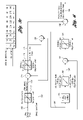
It is possible, when the driver demand results in a desired battery power that is clipped to either the battery charge limit or the battery discharge limit, for the profiled battery power to be affected by actual engine power variations or perturbations during the calculation of the profiled battery power modifier at 198, which again could result in a slight performance degradation. To avoid this condition, the modified system of FIG. 7 can be used. The system of FIG. 7 combines functions of the system of FIG. 5 and the functions of the system of FIG. 6 so that an accurate battery power modifier can be calculated when the driver demand results in battery power clipped to the battery charge and discharge limits, as well as when a desired battery power is within the battery charge and discharge limits.
The system of FIG. 5 performs the profiling function perfectly without any undesired battery power profiling modifier when the driver demand results in desired battery power that is clipped to either the battery charge limit or the battery discharge limit. Under all other conditions, when the driver demand results in a desired battery power between the discharge and charge limits, an undesirable battery power profiling modifier can result. On the other hand, the system of FIG. 6 performs profiling perfectly without any undesired battery power profiling modifier when the driver demand results in desired battery power between discharge and charge limits. Under the condition when the driver demand results in desired battery power clipped to either the battery charge or discharge limit, the system of FIG. 6 can result in an undesired battery power profiling modifier.
The function of FIG. 5 and the function of FIG. 6 are mutually exclusive. One system can be used under a first set of conditions and the other system can be used under a second set of conditions. A combination of the functions of FIGS. 5 and 6 in the system of FIG. 7 thus is feasible under all conditions. Any change in actual engine power will not result in an undesired profiled battery power modifier.
In the system of FIG. 7, a driver demand for power at 200 is clipped at 202 to ensure that the system limits are not violated. The desired modified driver demand for power at 204 and the actual engine power at 206 are combined at summing point 208, where the actual power is subtracted from the modified power demand. The result of the combination of the actual engine power with the modified driver power demand is clipped at 210 to ensure that the battery discharge and charge power limits are not violated. The desired battery power at 212 is distributed to logic circuit 214.
The desired battery power at 212 is distributed to a profiling filter function circuit at 215. The filtered desired battery power value at 216 is clipped, as shown at 218. The desired battery power value at 212 is subtracted from the clipped battery power at 220. This is done at summing point 222. Concurrently with the determination of the profiled battery power modifier at 224, the system of FIG. 7 will add the actual engine power at 206 to the desired battery power at 212 to produce a power value at 226. This addition occurs at summing point 228. The value for power at 226 then is filtered at filtering circuit 230.
The filtered value at 232 is clipped to the actual engine power plus battery discharge power limit, and to the actual engine power plus battery charge power limit, as shown at 234. This produces a profiled power demand value at 236. Actual engine power then is subtracted at summing point 238 from the demand power at 236. Thus, the actual engine power that is added at 228 is subtracted at 238. After the battery power is clipped, the desired battery power is subtracted from the clipped battery power, as shown at 239. A profiled battery power modifier is produced at 240.
It is apparent from FIG. 7 that two profiled battery power modifiers are computed simultaneously. Either one or the other is used by the vehicle system controller depending upon the value of the desired battery power. This decision is made at logic block 214. It is determined at logic block 214 whether the desired battery power is greater than the battery charge power limits and whether the desired battery power is less than the battery discharge power limits. If the result of that inquiry is negative, the profiled battery power modifier determined at 224 is used. This is indicated at 242 in FIG. 7. On the other hand, if the inquiry at 214 is positive, the vehicle system controller will use the profiled battery power modifier at 240. This is indicated at 244 in FIG. 7.
Although embodiments of the invention have been described, it will be apparent to persons skilled in the art that modifications may be made without departing from the scope of the invention. All such modifications and equivalents thereof are intended to be within the scope of the invention as defined by the following claims.

Claims (23)

1. A control method for determining a desired wheel power in a hybrid electric vehicle powertrain having an engine power source and an electric power source that includes a battery, an electric generator and an electric motor, one power source complementing the other to meet a driver demand for power at the vehicle wheels, the control method comprising the steps of:
measuring a driver demand for power and measuring actual engine power;
subtracting actual engine power from the driver demand for power to determine desired battery power;
filtering the desired battery power using a calibrated filter function to obtain a filtered desired battery power; and
subtracting from the desired battery power the filtered desired battery power to obtain a profiled battery power modifier for use in determining a final desired wheel power.
2. The control method set forth in claim 1 wherein the driver demand for power is clipped to maximum and minimum system power limits to produce a modified driver demand for power.
3. The control method set forth in claim 1 wherein the desired battery power is clipped to prevent the desired battery power from exceeding battery charge and discharge power limits.
4. The control method set forth in claim 1 wherein the filtered desired battery power is clipped to prevent the battery discharge and charge power from exceeding battery charge and discharge power limits.
5. The control method set forth in claim 1 wherein filtering is accomplished using a calibrated filter function in a table of functions with a filter variable dependent upon vehicle speed.
6. A control method for determining a desired wheel power in a hybrid electric vehicle powertrain having an engine power source and an electric power source that includes a battery, an electric generator and an electric motor, one power source complementing the other to meet a driver demand for power at the vehicle wheels, the control method comprising the steps of:
measuring a driver demand for power and measuring actual engine power;
subtracting actual engine power from the driver demand for power to determine desired battery power;
adding actual engine power and the desired battery power;
filtering the sum of the actual engine power and the desired battery power using a calibrated filter function to produce a profiled filtered sum of actual engine power and desired battery power;
subtracting the actual engine power from the profiled filtered sum of actual engine power and desired battery power; and
subtracting from desired battery power the difference between the profiled filtered sum of actual engine power and desired battery power and the actual engine power to produce a profiled battery power modifier for use in determining final desired wheel power.
7. The control method set forth in claim 6 wherein the demand for power is clipped to maximum and minimum system power limits to produce a modified demand for power.
8. The control method set forth in claim 6 wherein the desired battery power is clipped to prevent the desired battery power from exceeding battery charge and discharge limits.
9. The control method set forth in claim 6 wherein the filtered sum of the actual engine power and the desired battery power is clipped to limit the sum of the desired battery power and actual engine power.
10. The control method set forth in claim 6 wherein the difference between the filtered sum of the desired battery power and the actual engine power is clipped to values within the battery charge and discharge limits.
11. The control method set forth in claim 6 wherein the calibrated filter function is a table function with a filter variable dependent upon vehicle speed.
12. A control method for determining a desired wheel power in a hybrid electric vehicle powertrain having an engine power source and an electric power source that includes a battery, an electric generator and an electric motor, one power source complementing the other to meet a driver demand for power at the vehicle wheels, the control method comprising the steps of:
measuring a driver demand for power and measuring actual engine power;
subtracting the actual engine power from the driver demand for power to determine desired battery power;
filtering the desired battery power using a calibrated filter function to obtain a filtered desired battery power;
subtracting from the desired battery power the filtered desired battery power to obtain a first profiled battery power modifier for use in determining a final desired wheel power;
adding the actual engine power and the desired battery power;
filtering the sum of the actual engine power and the desired battery power using a calibrated filter function to produce a profiled sum of desired battery power and actual power;
subtracting the actual engine power from the profiled sum of desired battery power and the actual engine power to produce a second profiled battery power modifier for determining final desired wheel power;
selecting the second profiled battery power modifier when the desired battery power is greater than a battery charge power limit and is less than a battery discharge power limit; and
selecting the first profiled battery power modifier when the desired battery power is less than the battery charge power limit and is greater than the battery discharge power limit.
13. The control method set forth in claim 12 wherein the calibrated filter function is a table function with a filter variable dependent on vehicle speed.
14. The control method set forth in claim 12 wherein the driver demand for power is clipped to maximum and minimum system power limits.
15. The control method set forth in claim 12 wherein the desired battery power is clipped to the battery charge and discharge limits.
16. The control method set forth in claim 12 wherein the filtered desired battery power is clipped to the battery charge and discharge limits.
17. The control method set forth in claim 12 wherein the sum of actual engine power and desired battery power is clipped to the battery charge and discharge limits.
18. The control method set forth in claim 12 wherein the difference between the driver demand for power and the actual engine power is clipped to the battery charge and discharge limits.
19. A control system for a powertrain for a wheeled hybrid electric vehicle having an engine power source and an electric power source that includes a battery, an electric generator and an electric motor, one power source complementing the other to meet a driver demand for power at vehicle wheels, the system comprising:
a controller for measuring a desired battery power by subtracting actual engine power from a driver demand for power; and
a filtering circuit for profiling desired battery power and subtracting the profiled desired battery power from the desired battery power whereby a profiled battery power modifier is developed for use in determining a final desired wheel power.
20. A control system for a powertrain for a wheeled hybrid electric vehicle having an engine power source and an electric power source that includes a battery, an electric generator and an electric motor, one power source complementing the other to meet a driver demand for power at vehicle wheels, the system comprising:
a controller for measuring a driver desired battery power by subtracting actual engine power from the driver demand for power; and
a filtering circuit for profiling the desired battery power;
the controller being configured further for subtracting the profiled desired battery power from the desired power, the difference between the profiled desired battery power and the desired battery power determining a profiled battery power modifier.
21. A control method for operating a hybrid electric powertrain during a transient event in which a change in driver demand for power occurs, the powertrain having an engine and a battery cooperatively arranged to deliver driving power to a driven element of the powertrain, the method comprising the steps of:
delivering a portion of the demanded power using the engine;
supplementing the power delivered by the engine with a controlled amount of power from the battery;
computing a battery power modifier; and
modifying transient battery power delivery changes using the battery power modifier at the instant of a change in driver power demand.
22. A control method for operating a hybrid electric powertrain having an engine and a battery cooperatively arranged to deliver driving power to a driven element of the powertrain, the method comprising the steps of:
delivering a portion of demanded power using the engine;
supplementing the power delivered by the engine with a controlled amount of battery power;
detecting transient engine torque fluctuations during steady state operation of the powertrain; and
modifying power delivered from the battery during instantaneous engine torque fluctuations whereby battery power delivery limits are not exceeded during steady state operation.
23. A control system for a powertrain for a wheeled hybrid electric vehicle having an engine power source and an electric power source that includes a battery, an electric generator and an electric motor, one power source complementing the other to meet a driver demand for power at vehicle wheels, the system comprising:
a controller configured to determine a driver desired battery power; and
a filtering circuit for profiling the desired battery power whereby a profiled desired battery power is obtained;
the controller being configured further for subtracting the profiled desired battery power from the desired battery power, whereby the difference between the profiled desired battery power and the desired battery power determines a profiled battery power modifier to modify battery power fluctuation during a change in driver power demand.
US11/276,491 2005-08-02 2006-03-02 Method and system for determining final desired wheel power in a hybrid electric vehicle powertrain Active 2027-11-22 US7617893B2 (en)

Priority Applications (1)

Application Number Priority Date Filing Date Title
US11/276,491 US7617893B2 (en) 2005-08-02 2006-03-02 Method and system for determining final desired wheel power in a hybrid electric vehicle powertrain

Applications Claiming Priority (2)

Application Number Priority Date Filing Date Title
US70464805P 2005-08-02 2005-08-02
US11/276,491 US7617893B2 (en) 2005-08-02 2006-03-02 Method and system for determining final desired wheel power in a hybrid electric vehicle powertrain

Publications (2)

Publication Number Publication Date
US20070029119A1 US20070029119A1 (en) 2007-02-08
US7617893B2 true US7617893B2 (en) 2009-11-17

Family

ID=37716633

Family Applications (1)

Application Number Title Priority Date Filing Date
US11/276,491 Active 2027-11-22 US7617893B2 (en) 2005-08-02 2006-03-02 Method and system for determining final desired wheel power in a hybrid electric vehicle powertrain

Country Status (1)

Country Link
US (1) US7617893B2 (en)

Cited By (32)

* Cited by examiner, † Cited by third party
Publication number Priority date Publication date Assignee Title
US20090173557A1 (en) * 2006-04-10 2009-07-09 Klaus Joos Defined internal combustion engine operation in vehicles having a hybrid drive
US20090319108A1 (en) * 2006-09-04 2009-12-24 Toshiyuki Kawai Electricity storage control apparatus and method of controlling eletricity storage
US20100006358A1 (en) * 2008-07-11 2010-01-14 Toyota Jidosha Kabushiki Kaisha Hybrid vehicle and control method thereof
US20130026973A1 (en) * 2011-07-26 2013-01-31 Gogoro, Inc. Apparatus, method and article for authentication, security and control of power storage devices, such as batteries
US20130103282A1 (en) * 2011-10-25 2013-04-25 Kia Motors Corporation System and method of controlling motor vehicle operation
US8862388B2 (en) 2011-07-26 2014-10-14 Gogoro, Inc. Apparatus, method and article for providing locations of power storage device collection, charging and distribution machines
US8862304B2 (en) 2011-07-26 2014-10-14 Gogoro, Inc. Apparatus, method and article for providing vehicle diagnostic data
US8878487B2 (en) 2011-07-26 2014-11-04 Gogoro, Inc. Apparatus, method and article for providing to a user device information regarding availability of portable electrical energy storage devices at a portable electrical energy storage device collection, charging and distribution machine
US9067593B2 (en) 2013-03-08 2015-06-30 Toyota Motor Engineering & Manufacturing North America, Inc. Hybrid vehicle launch control
US9124085B2 (en) 2013-11-04 2015-09-01 Gogoro Inc. Apparatus, method and article for power storage device failure safety
US9123035B2 (en) 2011-04-22 2015-09-01 Angel A. Penilla Electric vehicle (EV) range extending charge systems, distributed networks of charge kiosks, and charge locating mobile apps
US9129461B2 (en) 2011-07-26 2015-09-08 Gogoro Inc. Apparatus, method and article for collection, charging and distributing power storage devices, such as batteries
US9216687B2 (en) 2012-11-16 2015-12-22 Gogoro Inc. Apparatus, method and article for vehicle turn signals
US9275505B2 (en) 2011-07-26 2016-03-01 Gogoro Inc. Apparatus, method and article for physical security of power storage devices in vehicles
US9390566B2 (en) 2013-11-08 2016-07-12 Gogoro Inc. Apparatus, method and article for providing vehicle event data
US9407024B2 (en) 2014-08-11 2016-08-02 Gogoro Inc. Multidirectional electrical connector, plug and system
US9424697B2 (en) 2011-07-26 2016-08-23 Gogoro Inc. Apparatus, method and article for a power storage device compartment
US9437058B2 (en) 2011-07-26 2016-09-06 Gogoro Inc. Dynamically limiting vehicle operation for best effort economy
US9552682B2 (en) 2011-07-26 2017-01-24 Gogoro Inc. Apparatus, method and article for redistributing power storage devices, such as batteries, between collection, charging and distribution machines
US9597973B2 (en) 2011-04-22 2017-03-21 Angel A. Penilla Carrier for exchangeable batteries for use by electric vehicles
USD789883S1 (en) 2014-09-04 2017-06-20 Gogoro Inc. Collection, charging and distribution device for portable electrical energy storage devices
US9770996B2 (en) 2013-08-06 2017-09-26 Gogoro Inc. Systems and methods for powering electric vehicles using a single or multiple power cells
US9830753B2 (en) 2011-07-26 2017-11-28 Gogoro Inc. Apparatus, method and article for reserving power storage devices at reserving power storage device collection, charging and distribution machines
US9837842B2 (en) 2014-01-23 2017-12-05 Gogoro Inc. Systems and methods for utilizing an array of power storage devices, such as batteries
US10055911B2 (en) 2011-07-26 2018-08-21 Gogoro Inc. Apparatus, method and article for authentication, security and control of power storage devices, such as batteries, based on user profiles
US10065525B2 (en) 2013-08-06 2018-09-04 Gogoro Inc. Adjusting electric vehicle systems based on an electrical energy storage device thermal profile
US10186094B2 (en) 2011-07-26 2019-01-22 Gogoro Inc. Apparatus, method and article for providing locations of power storage device collection, charging and distribution machines
US10421462B2 (en) 2015-06-05 2019-09-24 Gogoro Inc. Systems and methods for vehicle load detection and response
US10839451B2 (en) 2011-04-22 2020-11-17 Emerging Automotive, Llc Systems providing electric vehicles with access to exchangeable batteries from available battery carriers
US11075530B2 (en) 2013-03-15 2021-07-27 Gogoro Inc. Modular system for collection and distribution of electric storage devices
US11222485B2 (en) 2013-03-12 2022-01-11 Gogoro Inc. Apparatus, method and article for providing information regarding a vehicle via a mobile device
US11710105B2 (en) 2013-03-12 2023-07-25 Gogoro Inc. Apparatus, method and article for changing portable electrical power storage device exchange plans

Families Citing this family (8)

* Cited by examiner, † Cited by third party
Publication number Priority date Publication date Assignee Title
JP4900693B2 (en) * 2006-11-27 2012-03-21 アイシン・エィ・ダブリュ株式会社 Hybrid drive unit
US8224514B2 (en) * 2007-11-03 2012-07-17 GM Global Technology Operations LLC Creation and depletion of short term power capability in a hybrid electric vehicle
FR2930086B1 (en) * 2008-04-10 2012-04-20 Peugeot Citroen Automobiles Sa METHOD AND DEVICE FOR CONTROLLING AN ENERGY OVERLOAD
US8296032B2 (en) * 2008-12-16 2012-10-23 Ford Global Technologies, Llc Hybrid vehicle and a method of control for improved power management
US8813593B2 (en) * 2009-11-30 2014-08-26 Eaton Corporation Adapter for connecting a countershaft transmission with a hydraulic launch assist system
JPWO2011125865A1 (en) * 2010-04-05 2013-07-11 本田技研工業株式会社 Control device for hybrid vehicle
JP5700362B2 (en) * 2011-01-31 2015-04-15 スズキ株式会社 Hybrid vehicle
US20140214346A1 (en) * 2013-01-25 2014-07-31 Cummins Inc. Adaptive available power estimation for high voltage lithium ion battery

Citations (31)

* Cited by examiner, † Cited by third party
Publication number Priority date Publication date Assignee Title
US4218624A (en) * 1977-05-31 1980-08-19 Schiavone Edward L Electrical vehicle and method
US5285111A (en) * 1993-04-27 1994-02-08 General Motors Corporation Integrated hybrid transmission with inertia assisted launch
US5343970A (en) * 1992-09-21 1994-09-06 Severinsky Alex J Hybrid electric vehicle
US5619417A (en) * 1994-11-23 1997-04-08 Chrysler Corporation Battery monitoring system for an electric vehicle
US5637987A (en) * 1995-12-18 1997-06-10 General Motors Corporation Regenerative vehicle launch
US5939861A (en) * 1996-05-24 1999-08-17 Hino Jidosha Kogyo Kabushiki Kaisha Control system for on-vehicle battery
US6131680A (en) * 1996-05-20 2000-10-17 Toyota Jidosha Kabushiki Kaisha Power output apparatus and method of controlling the same
US6173574B1 (en) * 1998-07-07 2001-01-16 Denso Corporation Hybrid electric vehicle control apparatus for maximizing vehicle engine operating efficiency
US6208034B1 (en) * 1998-07-13 2001-03-27 Toyota Jidosha Kabushiki Kaisha Power output device and control method of the power output device and hybrid vehicle driven by the power output device
US6269290B1 (en) * 1998-07-01 2001-07-31 Denso Corporation Engine-motor hybrid vehicle control apparatus and method having engine performance Lessening compensation
US6330504B1 (en) * 1999-04-12 2001-12-11 Nissan Motor Co., Ltd. Vehicle driving force control with operator power demand responsive correction
US6336063B1 (en) * 2000-10-31 2002-01-01 Volvo Car Corporation Method and arrangement in a hybrid vehicle for improving battery state-of-charge control and minimizing driver perceptible disturbances
US6344732B2 (en) * 2000-03-23 2002-02-05 Toyota Jidosha Kabushiki Kaisha Electric energy charging control apparatus and method for hybrid vehicle
US6364807B1 (en) * 2000-06-30 2002-04-02 Ford Global Technologies, Inc. Control strategy for a hybrid powertrain for an automotive vehicle
US6401016B1 (en) * 1999-11-12 2002-06-04 Nissan Motor Co., Ltd. Vehicle control device
US6445247B1 (en) * 2001-06-01 2002-09-03 Qualcomm Incorporated Self-controlled high efficiency power amplifier
US20020123836A1 (en) * 2001-03-01 2002-09-05 Nissan Motor Co., Ltd. Vehicle drive system and vehicle controlling method
US6456041B1 (en) * 1998-12-28 2002-09-24 Yamaha Hatsudoki Kanushiki Kaisha Power supply system for electric vehicle
US6490511B1 (en) 2000-11-10 2002-12-03 Ford Motor Company Torque-based monitor in a hybrid electric vehicle
US6553287B1 (en) 2001-10-19 2003-04-22 Ford Global Technologies, Inc. Hybrid electric vehicle control strategy to achieve maximum wide open throttle acceleration performance
US6555927B1 (en) 1999-11-19 2003-04-29 Toyota Jidosha Kabushiki Kaisha Vehicular engine starting control apparatus and vehicular engine starting control method
US20030094816A1 (en) * 2001-03-06 2003-05-22 Isamu Kazama Hybrid vehicle control system and control method
US20040006419A1 (en) * 2002-04-09 2004-01-08 Toyota Jidosha Kabushiki Kaisha Power output apparatus and automobile
US6688411B2 (en) 2001-11-09 2004-02-10 Ford Global Technologies, Llc Hybrid electric vehicle and a method for operating a hybrid electric vehicle
US20050080537A1 (en) * 2003-10-14 2005-04-14 Cawthorne William R. Optimal selection of input torque considering battery utilization for a hybrid electric vehicle
US20050077867A1 (en) * 2003-10-14 2005-04-14 Cawthorne William R. Method of determining battery power limits for an energy storage system of a hybrid electric vehicle
US20050182526A1 (en) * 2004-02-14 2005-08-18 Hubbard Gregory A. Optimal selection of input torque with stability of power flow for a hybrid electric vehicle
US20050246076A1 (en) * 2004-04-30 2005-11-03 Jyh-Shin Chen Torque management algorithm for hybrid electric vehicles
US20050266957A1 (en) * 2004-05-11 2005-12-01 Yusuke Kamijo Power output apparatus and control method of the same
US20060022642A1 (en) * 2004-07-30 2006-02-02 Ford Global Technologies, Llc Closed loop control of battery power limits based on voltage
US20070021267A1 (en) * 2005-07-19 2007-01-25 Denso Corporation Engine controller and control method

Patent Citations (33)

* Cited by examiner, † Cited by third party
Publication number Priority date Publication date Assignee Title
US4218624A (en) * 1977-05-31 1980-08-19 Schiavone Edward L Electrical vehicle and method
US5343970A (en) * 1992-09-21 1994-09-06 Severinsky Alex J Hybrid electric vehicle
US5285111A (en) * 1993-04-27 1994-02-08 General Motors Corporation Integrated hybrid transmission with inertia assisted launch
US5619417A (en) * 1994-11-23 1997-04-08 Chrysler Corporation Battery monitoring system for an electric vehicle
US5637987A (en) * 1995-12-18 1997-06-10 General Motors Corporation Regenerative vehicle launch
US6131680A (en) * 1996-05-20 2000-10-17 Toyota Jidosha Kabushiki Kaisha Power output apparatus and method of controlling the same
US5939861A (en) * 1996-05-24 1999-08-17 Hino Jidosha Kogyo Kabushiki Kaisha Control system for on-vehicle battery
US6269290B1 (en) * 1998-07-01 2001-07-31 Denso Corporation Engine-motor hybrid vehicle control apparatus and method having engine performance Lessening compensation
US6173574B1 (en) * 1998-07-07 2001-01-16 Denso Corporation Hybrid electric vehicle control apparatus for maximizing vehicle engine operating efficiency
US6208034B1 (en) * 1998-07-13 2001-03-27 Toyota Jidosha Kabushiki Kaisha Power output device and control method of the power output device and hybrid vehicle driven by the power output device
US6456041B1 (en) * 1998-12-28 2002-09-24 Yamaha Hatsudoki Kanushiki Kaisha Power supply system for electric vehicle
US6330504B1 (en) * 1999-04-12 2001-12-11 Nissan Motor Co., Ltd. Vehicle driving force control with operator power demand responsive correction
US6401016B1 (en) * 1999-11-12 2002-06-04 Nissan Motor Co., Ltd. Vehicle control device
US6555927B1 (en) 1999-11-19 2003-04-29 Toyota Jidosha Kabushiki Kaisha Vehicular engine starting control apparatus and vehicular engine starting control method
US6344732B2 (en) * 2000-03-23 2002-02-05 Toyota Jidosha Kabushiki Kaisha Electric energy charging control apparatus and method for hybrid vehicle
US6364807B1 (en) * 2000-06-30 2002-04-02 Ford Global Technologies, Inc. Control strategy for a hybrid powertrain for an automotive vehicle
US6336063B1 (en) * 2000-10-31 2002-01-01 Volvo Car Corporation Method and arrangement in a hybrid vehicle for improving battery state-of-charge control and minimizing driver perceptible disturbances
US6490511B1 (en) 2000-11-10 2002-12-03 Ford Motor Company Torque-based monitor in a hybrid electric vehicle
US20020123836A1 (en) * 2001-03-01 2002-09-05 Nissan Motor Co., Ltd. Vehicle drive system and vehicle controlling method
US6662096B2 (en) * 2001-03-01 2003-12-09 Nissan Motor Co., Ltd. Vehicle drive system and vehicle controlling method
US20030094816A1 (en) * 2001-03-06 2003-05-22 Isamu Kazama Hybrid vehicle control system and control method
US6445247B1 (en) * 2001-06-01 2002-09-03 Qualcomm Incorporated Self-controlled high efficiency power amplifier
US6553287B1 (en) 2001-10-19 2003-04-22 Ford Global Technologies, Inc. Hybrid electric vehicle control strategy to achieve maximum wide open throttle acceleration performance
US6688411B2 (en) 2001-11-09 2004-02-10 Ford Global Technologies, Llc Hybrid electric vehicle and a method for operating a hybrid electric vehicle
US6816759B2 (en) * 2002-04-09 2004-11-09 Toyota Jidosha Kabushiki Kaisha Power output apparatus and automobile
US20040006419A1 (en) * 2002-04-09 2004-01-08 Toyota Jidosha Kabushiki Kaisha Power output apparatus and automobile
US20050080537A1 (en) * 2003-10-14 2005-04-14 Cawthorne William R. Optimal selection of input torque considering battery utilization for a hybrid electric vehicle
US20050077867A1 (en) * 2003-10-14 2005-04-14 Cawthorne William R. Method of determining battery power limits for an energy storage system of a hybrid electric vehicle
US20050182526A1 (en) * 2004-02-14 2005-08-18 Hubbard Gregory A. Optimal selection of input torque with stability of power flow for a hybrid electric vehicle
US20050246076A1 (en) * 2004-04-30 2005-11-03 Jyh-Shin Chen Torque management algorithm for hybrid electric vehicles
US20050266957A1 (en) * 2004-05-11 2005-12-01 Yusuke Kamijo Power output apparatus and control method of the same
US20060022642A1 (en) * 2004-07-30 2006-02-02 Ford Global Technologies, Llc Closed loop control of battery power limits based on voltage
US20070021267A1 (en) * 2005-07-19 2007-01-25 Denso Corporation Engine controller and control method

Cited By (61)

* Cited by examiner, † Cited by third party
Publication number Priority date Publication date Assignee Title
US20090173557A1 (en) * 2006-04-10 2009-07-09 Klaus Joos Defined internal combustion engine operation in vehicles having a hybrid drive
US8167066B2 (en) * 2006-04-10 2012-05-01 Robert Bosch Gmbh Defined internal combustion engine operation in vehicles having a hybrid drive
US20090319108A1 (en) * 2006-09-04 2009-12-24 Toshiyuki Kawai Electricity storage control apparatus and method of controlling eletricity storage
US8180508B2 (en) * 2006-09-04 2012-05-15 Toyota Jidosha Kabushiki Kaisha Electricity storage control apparatus and method of controlling electricity storage
US20100006358A1 (en) * 2008-07-11 2010-01-14 Toyota Jidosha Kabushiki Kaisha Hybrid vehicle and control method thereof
US8002058B2 (en) * 2008-07-11 2011-08-23 Toyota Jidosha Kabushiki Kaisha Hybrid vehicle and control method thereof
US9738168B2 (en) 2011-04-22 2017-08-22 Emerging Automotive, Llc Cloud access to exchangeable batteries for use by electric vehicles
US10245964B2 (en) 2011-04-22 2019-04-02 Emerging Automotive, Llc Electric vehicle batteries and stations for charging batteries
US9129272B2 (en) 2011-04-22 2015-09-08 Angel A. Penilla Methods for providing electric vehicles with access to exchangeable batteries and methods for locating, accessing and reserving batteries
US10086714B2 (en) 2011-04-22 2018-10-02 Emerging Automotive, Llc Exchangeable batteries and stations for charging batteries for use by electric vehicles
US10839451B2 (en) 2011-04-22 2020-11-17 Emerging Automotive, Llc Systems providing electric vehicles with access to exchangeable batteries from available battery carriers
US9925882B2 (en) 2011-04-22 2018-03-27 Emerging Automotive, Llc Exchangeable batteries for use by electric vehicles
US9597973B2 (en) 2011-04-22 2017-03-21 Angel A. Penilla Carrier for exchangeable batteries for use by electric vehicles
US9335179B2 (en) 2011-04-22 2016-05-10 Angel A. Penilla Systems for providing electric vehicles data to enable access to charge stations
US9193277B1 (en) 2011-04-22 2015-11-24 Angel A. Penilla Systems providing electric vehicles with access to exchangeable batteries
US9177305B2 (en) 2011-04-22 2015-11-03 Angel A. Penilla Electric vehicles (EVs) operable with exchangeable batteries and applications for locating kiosks of batteries and reserving batteries
US9123035B2 (en) 2011-04-22 2015-09-01 Angel A. Penilla Electric vehicle (EV) range extending charge systems, distributed networks of charge kiosks, and charge locating mobile apps
US9177306B2 (en) 2011-04-22 2015-11-03 Angel A. Penilla Kiosks for storing, charging and exchanging batteries usable in electric vehicles and servers and applications for locating kiosks and accessing batteries
US10186094B2 (en) 2011-07-26 2019-01-22 Gogoro Inc. Apparatus, method and article for providing locations of power storage device collection, charging and distribution machines
US10209090B2 (en) * 2011-07-26 2019-02-19 Gogoro Inc. Apparatus, method and article for authentication, security and control of power storage devices, such as batteries
US11139684B2 (en) 2011-07-26 2021-10-05 Gogoro Inc. Apparatus, method and article for a power storage device compartment
US9176680B2 (en) 2011-07-26 2015-11-03 Gogoro Inc. Apparatus, method and article for providing vehicle diagnostic data
US9182244B2 (en) * 2011-07-26 2015-11-10 Gogoro Inc. Apparatus, method and article for authentication, security and control of power storage devices, such as batteries
US20130026973A1 (en) * 2011-07-26 2013-01-31 Gogoro, Inc. Apparatus, method and article for authentication, security and control of power storage devices, such as batteries
US10573103B2 (en) 2011-07-26 2020-02-25 Gogoro Inc. Apparatus, method and article for physical security of power storage devices in vehicles
US9275505B2 (en) 2011-07-26 2016-03-01 Gogoro Inc. Apparatus, method and article for physical security of power storage devices in vehicles
US10546438B2 (en) 2011-07-26 2020-01-28 Gogoro Inc. Apparatus, method and article for providing vehicle diagnostic data
US9830753B2 (en) 2011-07-26 2017-11-28 Gogoro Inc. Apparatus, method and article for reserving power storage devices at reserving power storage device collection, charging and distribution machines
US10459471B2 (en) 2011-07-26 2019-10-29 Gorogo Inc. Apparatus, method and article for collection, charging and distributing power storage devices, such as batteries
US9129461B2 (en) 2011-07-26 2015-09-08 Gogoro Inc. Apparatus, method and article for collection, charging and distributing power storage devices, such as batteries
US9424697B2 (en) 2011-07-26 2016-08-23 Gogoro Inc. Apparatus, method and article for a power storage device compartment
US9437058B2 (en) 2011-07-26 2016-09-06 Gogoro Inc. Dynamically limiting vehicle operation for best effort economy
US9552682B2 (en) 2011-07-26 2017-01-24 Gogoro Inc. Apparatus, method and article for redistributing power storage devices, such as batteries, between collection, charging and distribution machines
US8996212B2 (en) 2011-07-26 2015-03-31 Gogoro Inc. Apparatus, method and article for providing vehicle diagnostic data
US11772493B2 (en) 2011-07-26 2023-10-03 Gogoro Inc. Apparatus, method and article for authentication, security and control of power storage devices, such as batteries
US10345843B2 (en) 2011-07-26 2019-07-09 Gogoro Inc. Apparatus, method and article for redistributing power storage devices, such as batteries, between collection, charging and distribution machines
US20140028089A1 (en) * 2011-07-26 2014-01-30 Hok-Sum Horace Luke Apparatus, method and article for authentication, security and control of power storage devices, such as batteries
US10529151B2 (en) 2011-07-26 2020-01-07 Gogoro Inc. Apparatus, method and article for reserving power storage devices at reserving power storage device collection, charging and distribution machines
US8878487B2 (en) 2011-07-26 2014-11-04 Gogoro, Inc. Apparatus, method and article for providing to a user device information regarding availability of portable electrical energy storage devices at a portable electrical energy storage device collection, charging and distribution machine
US9911252B2 (en) 2011-07-26 2018-03-06 Gogoro Inc. Apparatus, method and article for providing to a user device information regarding availability of portable electrical energy storage devices at a portable electrical energy storage device collection, charging and distribution machine
US9908506B2 (en) 2011-07-26 2018-03-06 Gogoro Inc. Apparatus, method and article for physical security of power storage devices in vehicles
US8862304B2 (en) 2011-07-26 2014-10-14 Gogoro, Inc. Apparatus, method and article for providing vehicle diagnostic data
US10055911B2 (en) 2011-07-26 2018-08-21 Gogoro Inc. Apparatus, method and article for authentication, security and control of power storage devices, such as batteries, based on user profiles
US8862388B2 (en) 2011-07-26 2014-10-14 Gogoro, Inc. Apparatus, method and article for providing locations of power storage device collection, charging and distribution machines
US20130103282A1 (en) * 2011-10-25 2013-04-25 Kia Motors Corporation System and method of controlling motor vehicle operation
US9108623B2 (en) * 2011-10-25 2015-08-18 Hyundai Motor Company System and method of controlling motor vehicle operation
US9216687B2 (en) 2012-11-16 2015-12-22 Gogoro Inc. Apparatus, method and article for vehicle turn signals
US9067593B2 (en) 2013-03-08 2015-06-30 Toyota Motor Engineering & Manufacturing North America, Inc. Hybrid vehicle launch control
US9340200B2 (en) 2013-03-08 2016-05-17 Toyota Motor Engineering & Manufacturing North America, Inc. Hybrid vehicle launch control
US11710105B2 (en) 2013-03-12 2023-07-25 Gogoro Inc. Apparatus, method and article for changing portable electrical power storage device exchange plans
US11222485B2 (en) 2013-03-12 2022-01-11 Gogoro Inc. Apparatus, method and article for providing information regarding a vehicle via a mobile device
US11075530B2 (en) 2013-03-15 2021-07-27 Gogoro Inc. Modular system for collection and distribution of electric storage devices
US10065525B2 (en) 2013-08-06 2018-09-04 Gogoro Inc. Adjusting electric vehicle systems based on an electrical energy storage device thermal profile
US9770996B2 (en) 2013-08-06 2017-09-26 Gogoro Inc. Systems and methods for powering electric vehicles using a single or multiple power cells
US9124085B2 (en) 2013-11-04 2015-09-01 Gogoro Inc. Apparatus, method and article for power storage device failure safety
US10467827B2 (en) 2013-11-08 2019-11-05 Gogoro Inc. Apparatus, method and article for providing vehicle event data
US9390566B2 (en) 2013-11-08 2016-07-12 Gogoro Inc. Apparatus, method and article for providing vehicle event data
US9837842B2 (en) 2014-01-23 2017-12-05 Gogoro Inc. Systems and methods for utilizing an array of power storage devices, such as batteries
US9407024B2 (en) 2014-08-11 2016-08-02 Gogoro Inc. Multidirectional electrical connector, plug and system
USD789883S1 (en) 2014-09-04 2017-06-20 Gogoro Inc. Collection, charging and distribution device for portable electrical energy storage devices
US10421462B2 (en) 2015-06-05 2019-09-24 Gogoro Inc. Systems and methods for vehicle load detection and response

Also Published As

Publication number Publication date
US20070029119A1 (en) 2007-02-08

Similar Documents

Publication Publication Date Title
US7617893B2 (en) Method and system for determining final desired wheel power in a hybrid electric vehicle powertrain
US6991053B2 (en) Closed-loop power control for hybrid electric vehicles
JP3489475B2 (en) Driving force control device
US7576501B2 (en) Method for controlling a hybrid electric vehicle powertrain with divided power flow paths
US10525968B2 (en) Method for controlling a drive device of a hybrid vehicle and hybrid vehicle
US9545839B2 (en) Hybrid electric vehicle powertrain with enhanced reverse drive performance
US8473133B2 (en) Transient operation energy management strategy for a hybrid electric vehicle powertrain
US8140204B2 (en) Charge depleting energy management strategy for plug-in hybrid electric vehicles
US7467033B2 (en) Control method for a vehicle powertrain with protection against low load conditions
US7472769B2 (en) Hybrid vehicle control system
JP4063744B2 (en) Control device for hybrid vehicle
US7117964B1 (en) Control system for a hybrid electric vehicle powertrain
US8676415B2 (en) Engine power demand load-leveling for a hybrid electric vehicle
US9162665B2 (en) Kick-down shift control device for electric vehicle
US20100063658A1 (en) Engine Speed Control and Battery Power Scheduling Strategy for an Engine in a Hybrid Electric Vehicle Powertrain
US9132747B2 (en) Control device of vehicle drive device
US7431111B2 (en) Hybrid power output apparatus and control method
US7229381B2 (en) Method for controlling engine starts for a vehicle powertrain
US9834198B2 (en) Generator power control
US20080119975A1 (en) Hybrid Electric Vehicle Powertrain with Engine Start and Transmission Shift Arbitration
US20090210108A1 (en) Engine Speed Control for an Engine in a Hybrid Electric Vehicle Powertrain for Improved Noise, Vibration and Harshness
US20070298928A1 (en) Hybrid vehicle and control method of the same
US7273439B2 (en) Strategy for mapping motor speed to calculate driver power demand in a hybrid electric vehicle
US20210213931A1 (en) Drive force control system for vehicle
US10479348B2 (en) Hybrid vehicle and method of reducing engine lugging

Legal Events

Date Code Title Description
AS Assignment

Owner name: FORD MOTOR COMPANY, MICHIGAN

Free format text: ASSIGNMENT OF ASSIGNORS INTEREST;ASSIGNORS:SYED, FAZAL;KUANG, MING;CZUBAY, JOHN;AND OTHERS;REEL/FRAME:017243/0861;SIGNING DATES FROM 20060131 TO 20060207

Owner name: FORD GLOBAL TECHNOLOGIES, LLC, MICHIGAN

Free format text: ASSIGNMENT OF ASSIGNORS INTEREST;ASSIGNOR:FORD MOTOR COMPANY;REEL/FRAME:017243/0932

Effective date: 20060221

STCF Information on status: patent grant

Free format text: PATENTED CASE

CC Certificate of correction
FPAY Fee payment

Year of fee payment: 4

FPAY Fee payment

Year of fee payment: 8

MAFP Maintenance fee payment

Free format text: PAYMENT OF MAINTENANCE FEE, 12TH YEAR, LARGE ENTITY (ORIGINAL EVENT CODE: M1553); ENTITY STATUS OF PATENT OWNER: LARGE ENTITY

Year of fee payment: 12