US7619824B2 - Variable optical arrays and variable manufacturing methods - Google Patents
Variable optical arrays and variable manufacturing methods Download PDFInfo
- Publication number
- US7619824B2 US7619824B2 US11/829,055 US82905507A US7619824B2 US 7619824 B2 US7619824 B2 US 7619824B2 US 82905507 A US82905507 A US 82905507A US 7619824 B2 US7619824 B2 US 7619824B2
- Authority
- US
- United States
- Prior art keywords
- array
- screen
- light
- optical system
- lens
- Prior art date
- Legal status (The legal status is an assumption and is not a legal conclusion. Google has not performed a legal analysis and makes no representation as to the accuracy of the status listed.)
- Expired - Fee Related, expires
Links
Images


Classifications
-
- G—PHYSICS
- G03—PHOTOGRAPHY; CINEMATOGRAPHY; ANALOGOUS TECHNIQUES USING WAVES OTHER THAN OPTICAL WAVES; ELECTROGRAPHY; HOLOGRAPHY
- G03B—APPARATUS OR ARRANGEMENTS FOR TAKING PHOTOGRAPHS OR FOR PROJECTING OR VIEWING THEM; APPARATUS OR ARRANGEMENTS EMPLOYING ANALOGOUS TECHNIQUES USING WAVES OTHER THAN OPTICAL WAVES; ACCESSORIES THEREFOR
- G03B21/00—Projectors or projection-type viewers; Accessories therefor
- G03B21/54—Accessories
- G03B21/56—Projection screens
- G03B21/60—Projection screens characterised by the nature of the surface
Definitions
- the present invention relates to lens arrays, methods of making lens arrays, and the construction of various lens array systems.
- the invention overcomes the aforementioned shortcomings by taking a completely different approach. Specifically, the invention divides the lens focusing process into two or more surfaces that incorporate multiple axial optic elements on each surface; where “axial optics” includes the use of cylindrical lenses as examples. In the case of cylindrical lenses, if the lenses are cut transverse to the axis of the cylinder, the cut will expose the same contour as cross cuts made elsewhere along the lens.
- the axial optics may be manufactured by press-forming (using deformable solids), roll-forming (using deformable solids), molding (using a liquid), machining, or by suspended film (which could utilize deformable solids or liquids). If press-forming is used, then a deformable plastic is sandwiched by film and then pressed together by a tool. The tool forms the film and supporting plastic into the desired optic shape. The resultant optic may be cut according to the dimensions of the tool, or the tool may release the optic, which can be pulled forward incrementally for cutting. If roll-forming is used, the press-forming tool may be modified to a cylinder and the films and deformable plastic material may be rolled through in a continuous process. If suspended film is used, then there are several options.
- both sides of an optic may have a suspended film that is transparent. This leads to practical applications including a multi-image device, and a rear-projection screen, both of which are described in greater detail below.
- one side of the optic may use a reflective film, leading to practical applications such as a front projection screen described in greater detail below and a multi-image device of the type described in a related U.S. patent application that is titled “Reflective Multi-Image Surface”, filed on Nov. 18, 2004, now U.S. Pat. No. 7,123,411.
- the powerful practical impact of the present invention is that a great number of optical elements may be created in a small area (approximately 90,000 discrete lenses per square foot), and the lens curvature may be varied without necessarily having to change the tooling for the lens elements.
- FIG. 1A is an elevated view of a first axial optic element having a curved surface that receives light, and a flat surface where the light exits, and the exiting light is focused into a line at a focal surface.
- FIG. 1B is an elevated view of a second axial optic element having a flat surface that receives light, and a curved surface where the light exits, and the exiting light is focused into a line at a focal surface.
- FIG. 1C is an elevated view showing a physical blockage of light.
- FIG. 1D is an elevated view showing a partial physical blockage of light.
- FIG. 2A is an elevated view of the first and second axial optic elements set perpendicularly with respect to each other, oriented with curved surfaces towards each other, and further illustrating a single focal point for light passing through both axial optic elements.
- FIG. 2B is a top view of FIG. 2A , wherein the first and second axial optic elements set perpendicularly with respect to each other, oriented with curved surfaces towards each other, and further illustrating a single focal point for light passing through both axial optic elements.
- FIG. 2C is a side view of FIG. 2A where the first and second axial optic elements are set perpendicularly with respect to each other, oriented with curved surfaces towards each other, and further illustrating a single focal point for light passing through both axial optic elements.
- FIG. 3A is an elevated view of the first and second axial optic elements set perpendicularly with respect to each other, oriented with flat surfaces towards each other, and further illustrating a single focal point for light passing through both axial optic elements.
- FIG. 3B is a top view of FIG. 3A , wherein the first and second axial optic elements set perpendicularly with respect to each other, oriented with curved surfaces towards each other, and further illustrating a single focal point for light passing through both axial optic elements.
- FIG. 3C is a side view of FIG. 3A , wherein the first and second axial optic elements set perpendicularly with respect to each other, oriented with curved surfaces towards each other, and further illustrating a single focal point for light passing through both axial optic elements.
- FIG. 4 is an elevated view of first and second axial optic elements disposed in a crossed relationship, oriented with the curved surfaces towards each other, wherein light is being collimated as it originates from a light source and passes through two crossed lenses.
- FIG. 5 is an elevated view of an array of axial lens elements.
- FIG. 6A is an elevated view of a first array of axial lens elements, and a second array of axial optic elements set perpendicularly with respect to each other, oriented with curved surfaces towards each other, and further illustrating a series of single focal points for light passing through both axial optic elements.
- FIG. 6B is another elevated view of the arrays of axial lens elements of FIG. 6B .
- FIG. 6C is a top view of FIG. 6A , wherein the first and second array of axial lens elements are disposed perpendicularly with respect to each other, oriented with curved surfaces towards each other.
- FIG. 7A is an elevated view of a first array of axial lens elements having a flat surface closest to the rounded surface of a second array of axial lens elements, wherein the first array is oriented above and perpendicularly with respect to the second array, and further illustrating an elevated view of the resulting projection.
- FIG. 7B is a side view of the embodiment shown in FIG. 7A .
- FIG. 7C is a top view of the embodiment shown in FIG. 7A .
- FIG. 8A is a top view of the overlapping area of first and second axial lens element arrays oriented perpendicularly, with curved surfaces facing each other, and a hidden view of the resulting projection.
- FIG. 8B is an elevated view of first and second axial lens element arrays oriented perpendicularly as shown in FIG. 8A , with curved surfaces facing each other, and an elevated view of the resulting projection.
- FIG. 8C is a top view of first and second axial lens element arrays oriented at a 45 degree orientation, with curved surfaces facing each other, and a hidden view of the resulting projection.
- FIG. 8D is an elevated view of first and second axial lens element arrays oriented at a 45 degree orientation as shown in FIG. 8C , with curved surfaces facing each other, and an elevated view of the resulting projection.
- FIG. 8E is a top view of first and second axial lens element arrays oriented in registry, with curved surfaces facing each other, and a hidden view of the resulting projection.
- FIG. 8F is an elevated view of first and second axial lens element arrays oriented in registry as shown in FIG. 8E , with curved surfaces facing each other, and an elevated view of the resulting projection.
- FIG. 9A is a side view of a first curved surface for an axial optical element array.
- FIG. 9B is a side view of a second curved surface for an axial optical element array.
- FIG. 9C is a side view of a third curved surface with baffles for an axial optical element array.
- FIG. 9D is a side view of a series of flat, apex-forming surfaces for an axial optical element array.
- FIG. 9E is a side view of a series of non-uniform curved surfaces for an axial optical element array.
- FIG. 10 illustrates an elevated view of a film suspended on a tool.
- FIG. 11 illustrates an elevated view of a mold with external attachments.
- FIG. 12 illustrates an elevated assembly view of the mold of FIG. 11 .
- FIG. 13 illustrates a rear projection screen system using the crossed optical array of the present invention.
- FIG. 14 illustrates the general concept of the class of practical application of a spatially-multiplexed image deconvolver with the respective positions of a light source, a Composite Image, a Lens Array, and two different Viewable Images within two Viewer Angular Regions, as well as example rays coming from selected Lens Source Groups.
- FIG. 15 illustrates a 9-by-9 array of pixels, totaling to 81 pixels, which make up the Composite Image, and one Source Image, which is made up of nine pixels.
- FIG. 16 illustrates the general characteristic of a lens when an image is placed at its focal point, the relation of the pixel placements in the Composite Image to the Viewable Image when central rays come from each of three pixels, and the arrangement of the pixels within each Lens Source Group being very specific, the placement of the pixel being in accord with the characteristic of refractive optics such that its energy is sent in the same direction as the other pixels that make up the source image to be sent toward a viewer.
- FIG. 17 illustrates the profile of three lenses, matched in focal length, size and location relative to the elements of the Composite Image, with each lens separating the image elements into different directions as illustrated in FIG. 16 .
- a 9-by-9 Lens Array overlaid on a 9-by-9 Lens Source Group, would deconvolve the spatially multiplexed elements in FIG. 14 to the nine individual Source Images, now Viewable Images.
- FIG. 18 illustrates a one-dimensional lens array
- FIG. 19 illustrates a two-dimensional lens array.
- FIG. 20 illustrates the basic idea of glass bead screens.
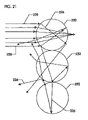
- FIG. 21 illustrates the crosstalk issues associated with glass beads.
- FIG. 22 illustrates incoming projector light passing into the cylindrical lenses and reflecting back out through the same lenses which are backed by a specular reflector.
- FIG. 23 illustrates one example of a film-suspension arrangement for creation of the closely-spaced cylindrical lens array.
- FIG. 24 illustrates the overall concept of clear film adhered with cylindrical morphology to bulk clear refractive fill material plus reflective film adhered with cylindrical morphology to the opposite side of the bulk fill.
- FIG. 25A illustrates a front elevated view of a typical individual cell, in which the effect of the arrangement in the invention is to produce a matrix of projection screen reflective cells with many advantages over traditional front projection screen technology, such as high-gain improved contrast and multiple imaging capabilities.
- FIG. 25B illustrates a side elevated view of the cell of FIG. 25A .
- FIG. 25C illustrates an elevated side view of the cell of FIG. 25A .
- FIG. 26 illustrates a highly flexible screen where small cell size leads to a thin, flexible screen.
- FIG. 27A is an elevated view of the press-forming process embodiment of the present invention.
- FIG. 27B is a side view of the press-forming process embodiment of FIG. 27A .
- FIG. 27C is a detail assembly view taken of area 27 C of FIG. 27B .
- FIG. 28A is an elevated view of the roll-forming process embodiment of the present invention.
- FIG. 28B is a side view of the roll-forming process embodiment of FIG. 27A .
- FIG. 28C is a detail assembly view taken of area 28 C of FIG. 27B .
- FIG. 29A is an elevated view of a crossed-array screen having striations.
- FIG. 29B is a front view of the crossed-array screen of FIG. 29A .
- FIG. 29C is a side view of the crossed-array screen of FIG. 29A .
- FIG. 29D is a detail view of circle 29 D of FIG. 29A .
- FIG. 30A is an elevated rear view of the crossed-array screen of FIG. 29A .
- FIG. 30B is a rotated section rear view of FIG. 30A , showing various light paths.
- FIG. 31 is a chart illustrating the effect of light's travel distance on its attenuation.
- FIG. 32 is a graph showing light's travel distance versus transmission for three different attenuation coefficients.
- Axial optics may be obtained by machining, or by molding, as described below.
- axial optics may be obtained by machining. Specifically, in a milling operation a piece of optic-compatible material can be mounted onto a milling bed and fed into a cutting tool (such as a ball mill or other cutting shapes) along a continuous axis to obtain a continuous cut that is linear when examined from at least one viewing perspective. The milling bed can then be offset to produce a cut that is also linear when observed with the same aforementioned perspective, and is nearly parallel to the first. These parallel cuts produce an axial optic. Continuing with additional parallel cuts can produce an array of axial optics.
- a cutting tool such as a ball mill or other cutting shapes
- the present invention divides the two-axis focusing process exhibited by standard optics (camera lenses, projector lenses, microscope lenses, etc.) into two or more one-axis stages by using two or more axial optic elements with two or more of the axes set more or less crosswise to one another.
- Employing crossed axial optics in such a manner makes manufacture of lens arrays much more practical and economical than with standard two-axis lens array manufacture.
- FIGS. 1A and 1B parallel rays of light are shown entering two lenses perpendicularly from above.
- the cylindrical lens focuses the light into a line. That is, the effect of focusing is in one direction that is aligned with the axis of the lens cylinder.
- the light rays converge to a concentration at a specific distance from the lens in accord with various properties, including, but not limited to, the curvature of the cylinder and the refractive index of the material from which the lens is made.
- the light After the light is concentrated to a line, if it is not interrupted by a physical blockage, the light (after already having come into focus) continues by diverging away from the point, the divergence angle being consistent with the angle of the original incoming ray. On one side of the concentrated line, the light converges on it from different directions. On the other side of the concentrated line, the light diverges as it continues to travel.
- this invention includes cases wherein a physical blockage 15 and 17 , in whole or in part, is used. Partial physical blockage 15 and 17 is also included in this invention. Physical blockage 15 and 17 is shown in FIGS. 1C and 1D . Non-limiting examples of uses of partial physical blockage 15 and 17 include the control of lens-effective apertures, the interaction of incoming light with pixels of existing images via intermediate focal planes that contain the images in a transmissive and/or reflective form, and encoding of information via spatial filtering. Examples of physical blockage material include, but are not limited to, photographic film, CCD video chips, and any other photosensitive material. Also, partial blockage 15 and 17 may be desired. An example case of partial blockage material 15 and 17 is an array of color filters.
- first cylindrical lens 14 a and second cylindrical lens 14 b in FIGS. 1A and 1B are aligned orthogonally with respect to each other, are stacked vertically, and aligned transversely to the path of incoming light, shown generally at 12 , (and as shown in FIGS. 2A , 2 B, 2 C, 3 A, 3 B, 3 C and 4 ), then first lens 14 a focuses incoming light 12 to exit light lines 16 which forms line 18 .
- the combined effect of both lenses 14 a , 14 b will be to focus the light to a spot 22 .
- This spot 22 approximately represents the crossing point of the two exit light lines 16 associated with each of the two lenses when considered independently.
- the incoming light 12 focused to spot 22 will be that which impinges an area approximately defined by the overlap area of the two cylindrical lenses. Accordingly, the crossed cylindrical lenses can operate together as a collector of light, as depicted in FIGS. 2A , 2 B, 2 C and 3 A, 3 B, and 3 C.
- FIGS. 2A , 2 B and 2 C show the two lenses with their curvatures toward each other, and FIGS. 3A , 3 B, and 3 C show the combination with the flats toward each other.
- the example lenses need not have curvature on one side and be flat on the other. In fact, putting the crossed cylindrical arrays on opposite sides of the same piece of material is nearly equivalent to the arrangement shown in FIG. 3A , 3 B, and 3 C. It should be further noted that the lenses need not be convex, although that is the common shape in the figures used for discussion of this invention. Further, the invention may have any number of axial-optics surfaces stacked in succession, so long as that number is at least two.
- FIG. 4 illustrates that the crossed lens array can be used to collimate light as readily as it can be used to collect light.
- light 28 emanating from a light source 26 placed at the composite focal point of the two lenses 14 a and 14 b , is allowed to radiate towards lens 14 a .
- Light 16 then exits first lens 14 b and diverges and collimates.
- Collimated light 30 exits from second lens 14 a . The light that falls under the influence of the area where the two lenses overlap will be collimated 30 more than it was when light 28 was first radiating outward from the source 26 .
- FIG. 5 shows that the surface on a piece of material can be provided with more than one axial optic.
- an axial lens array 32 comprising five cylindrical lenses is shown in abutment to one another. (It is not a requirement of this invention that all the axial optics on a surface be the same in cross section as seen in FIG. 9A-9E .)
- a piece of material with multiple cylindrical lenses 32 a can be crossed with another piece having multiple cylindrical lenses 32 b , thereby producing a two-dimensional lens array such as illustrated in FIGS. 6A , 6 B, and 6 C.
- the particular overlay area 20 associated with each cylindrical lens element is a collector of light that produces its own focal spot 24 using the light that falls upon that area 20 .
- This invention includes configurations where each axial optic on a piece of material is not necessarily the same as other axial optics on the same piece.
- the 25 overlap areas are shown bounded by dashed lines.
- every overlap area in FIGS. 6A , 6 B, and 6 C does not show impingement with light. This demonstrates that there are instances when it is desirable that the array not have light fall upon every element overlap area 20 .
- FIGS. 7A , 7 B, and 7 C illustrate a two-dimensional lens array 32 a , 32 b where the application is a collimator of light emanating from many sources 26 , each located at the focal spot 22 of the lenses 32 a , 32 b created by the overlap 20 of the axial optics 32 a , 32 b .
- this condition is the inverse use of the arrays 32 a , 32 b to their use in FIGS. 6A , 6 B and 6 C.
- the axes of two sets of axial-optics 32 a , 32 b need not be arranged perpendicularly with respect to one another. For example, continuing with the cylindrical optics illustration, FIGS.
- FIGS. 8E and 8F show that when the axes are aligned with each other, the result is focus into a series of parallel lines, rather than focus into an array of spots.
- the sets are oriented non-parallel, in other words, the longitudinal axis of the first optic is skew relative to the longitudinal axis of the second optic, as in FIGS. 8A-8D , focus into spots begins to take place.
- the spots are not symmetric, as they are with the sets oriented transverse to each other.
- FIGS. 8A , 8 B, 8 C, 8 D, 8 E, and 8 F as the pieces are rotated relative to each other, the resultant convergence of the impinging light moves from circle-like, to ellipse-like, to linear.
- the desired optical effects support the creation of an array of independent optical elements.
- the reference is to either axial optics of the set on the face of the same piece of material, or to the individual axial optics on another face.
- This is an important distinction of this invention relative to other optical systems, such as a Fresnel lens, the purpose of which is to collectively create a singular displacement or focal point for incoming parallel light.
- a Fresnel optical system for example, is intended to create only one image of a scene when using one system. Unlike the Fresnel, this invention will support production of a large number of images of a scene when using one system.
- axial optics are imbedded within the pieces of materials, such as with linear cavities in plastic, glass or other suitably transparent materials. Additionally, where appropriate, liquids and gases of various refractive and transparency qualities can be flowed within the system to alter the focusing, color, and other characteristics of a lens array.
- the current preferred embodiment which has been built and tested by the inventor, is a design wherein two pieces of axial optics are made by casting resin with axial lenses spaced 1/16′′ apart and having a focal length of 1 ⁇ 8′′. The two pieces, both of which use axial optics that are cylindrically shaped, are then crossed, as per FIGS. 2A , 2 B, and 2 C or FIGS. 3A , 3 B, and 3 C, to produce an array as depicted in FIGS. 6A , 6 B, and 6 C and FIGS. 7A , 7 B, and 7 C.
- this particular embodiment is currently preferred, the invention is not limited to the shapes, sizes, or manufacturing techniques used in this example.
- An extremely valuable feature of the invention is that it allows cost effective manufacture of two-dimensional lens arrays, and facilitates manufacture of lens arrays of a spatial density that would be impractical, if not impossible, using prior optical manufacturing methods. Also, in several embodiments of this invention, the optical characteristics can be readily changed even after fabrication.
- Optical computing, communication, and coding include, but are not limited to, the following optical examples: Optical computing, communication, and coding; rear-screen and front-screen projection for theaters, home entertainment and schools; advertisement signage and scoreboards; “eyeglasses” for military heads-up displays and for virtual reality systems to display a different three-dimensional image for each eye by collimating selected pixels; along with others.
- this invention is not limited to optical applications. This invention is also applicable to other regions of the electromagnetic spectrum, as well as to acoustic and other mechanical energies.
- a tool 134 is created by making a series of longitudinal cuts to create thin walls 102 spaced at a distance D of preferably 1 mm.
- Tool 134 is shown with v-shaped longitudinal cuts, but can also have square cuts. Holes (not shown) or even grooves, may be placed along the bottom of the cuts to provide communication for a differential pressure V.
- a sheet of film 104 transparent or reflective, is placed over the walls 102 . Then, differential pressure V is applied via the holes (not shown) between the walls 102 to pull the film 104 , and a curved axial optic 110 is formed. It is very important to understand that there is no further polishing of the optic that is required in order to have an optical quality surface.
- a crossed optical array is created.
- the space between the films 104 may be filled with a plastic (the term “plastic” is intended to be used generically in its broadest sense and not meant to be limited to “polymer”).
- a plastic is intended to be used generically in its broadest sense and not meant to be limited to “polymer”.
- One preferred plastic is the epoxy referred to above, which because of its low viscosity, pours like water between the films where it is then heated and cured.
- FIGS. 11 and 12 a mold is shown generally at 116 .
- Mold 116 has as supporting structure leg supports 118 , base support 120 , stabilization plate 122 , upright supports 124 , and spacing block 126 .
- Hinges 128 permit easy access to the inner cavity by permitting laterally swinging and removable hinged doors 130 . These doors 130 allow production personnel access to all necessary components concerning pre and post curing operations which may include secondary trimming.
- mold 116 has doors 130 , radiator 131 , radiator gasket 132 , vacuum bed 134 , and spacing gasket 136 .
- Tool 100 is placed within vacuum bed 134 , on each side.
- a temperature sensor array 140 is provided on the exterior of the mold 116 , as are external heating sources 142 (fixed onto doors 130 using a high temperature adhesive backing), high temperature fluid inlet hoses 144 , high temperature fluid outlet hoses 146 , and vacuum hoses 148 .
- the sheets can be combined with the use of gravity, adhesives, solvents, vacuum, fusion, pressure, mechanical devices, and other options. Edges of the stacked combinations can be left open or sealed. (Sealing allows for cleanliness and fluid containment; with the fluids being either gas or liquid or a combination of both.)
- the resultant array assemblies can be comprised of two or more axially-produced optical layers, with each layer being the same or different in figure, finish, material, or other characteristic suited to the application.
- FIG. 29A illustrates a top axial optical layer, and a bottom axial optical layer, with the longitudinal axis of the top axial optics being skew relative to the longitudinal axis of the bottom axial optics. It is possible to remove film 104 after the liquid filler (epoxy) cures. Removing film 104 removes a refractive index change at the interface between the film and the filler.
- hybrid reflection screen structure 280 by creation of outward pressure between two films 104 , 282 , using a more solidified inner material 284 at the production onset.
- hybrid screen is used in reference to a situation where a first array of optics are joined to a second array of optics, and this application expressly teaches three ways to achieve this: vacuum/molding ( FIGS. 11-12 ), press-forming ( FIGS. 27A-27C ), and roll-forming ( FIGS. 28A-28C ).
- a sheet of optically appropriate deformable material 284 is placed between the two films 104 , 282 , typically with one being reflective and the other being transmissive; although both films 104 , 282 could be transmissive if one desires the formation of a matrix of lenses.
- Films 104 , 282 may be made from polyethelene (PET).
- Deformable material 284 may be made from urethane. The arrangement, with the deformable material 284 positioned between the two films 104 , 282 is placed between a first tool 290 and a second tool 292 .
- First tool 290 has linear ridging 298 .
- deformable material 284 When a heated press is used, deformable material 284 may be more easily deformed if the deformable material 284 is selected to be thermally deformable. When the product is allowed to cool, the result is a fixed-shape hybrid screen 280 .
- hybrid is used in this document to refer to any screen that is provided with a first axial optical array in electromagnetic communication with a second axial optical array, and these arrays may be integrally joined as shown in FIGS. 11-12 , 27 A- 27 C, and 28 A- 28 C.
- the use of a heated press can also be used to activate and cure chemical processes in thermal-setting materials 284 , which is a variant of the aforementioned simple elevated temperature thermal deformation process.
- a sheet of optically appropriate deformable material 284 is placed between the two films 104 , 282 , typically with one being reflective and the other being transmissive; although both films 104 , 282 could be transmissive if one desires the formation of a matrix of lenses.
- the arrangement, with the deformable material 284 positioned between the two films 104 , 282 is placed between a first roller tool 294 and a second roller tool 296 .
- First roller tool 294 has linear ridging 298 .
- the following are stacked sequentially and fed through roller tools 294 , 296 : film 104 , deformable filler material 284 , and film 282 .
- the roller tools 294 , 296 apply pressure which forces the film 104 against the tooled ridges 298 to deform the film 104 between the ridges 298 into the form of catenary-like cross-sectioned cylinders 280 .
- the roller tools 294 , 296 are heated.
- deformable material 284 may be more easily deformed if the deformable material 284 is selected to be thermally deformable.
- the result is a fixed-shape hybrid screen 280 .
- a very high quality rear projection screen may be manufactured.
- a resultant array assembly can be used to form a rear projection screen 151 .
- a rear projection source 152 projects light through rear projection screen 151 which is a crossed optical array, resulting in a viewable image 154 .
- a spatially multiplexed image deconvolver (a decoder) may be created.
- a method for the deconvolving of a multiplexed image with a lens array such that viewers within different angle regions will see different individual source images.
- the number of images can be on the order of magnitude of the hundreds rather than the two or three available with prisms.
- the images can be selected by angular movements along more than one axis, compared to the one axis restriction of prismatic displays.
- a Source Image is an individual image whose elements are convolved (intermingled) with elements from other Source Images to form a Composite Image.
- the viewer sees a specific deconvolved Source Image within a certain range of angles during operation of this invention, the specific image being in accord with the invention's selectable parameters.
- the invention is most striking when it incorporates several Source Images, each viewable at different angles, but is capable of functioning with just one Source Image.
- An element, or pixel is a “piece” of a Source Image, which is located within a Lens Source Group of the Composite Image, as shown in FIG. 15 .
- the Composite Image also called the Multiplexed Image, is a convolution of all of the Source Images in such a way that the Lens Array in this invention will allow for deconvolving each Source Image, that is, sorting out, for the viewer, the pixels of each Source Image such that a coherent image is seen.
- the term also refers to the physical Composite Image, which may be made of various materials, and is located behind the Lens Array.
- the Composite Image without the aid of the deconvolution provided by the invention, looks to the eye like an incomprehensible collection of random spots.
- a Lens Source Group is the group of pixels behind a single lens within the Lens Array. There are generally as many Lens Source Groups as there are individual lenses in the Lens Array. In the preferred embodiment, a Lens Source Group includes at least one pixel from each Source Image.
- a Viewable Image is a Source Image as it is seen by a viewer. This image is one of the Source Images, after it has been deconvolved from the other Source Images in the Composite Image by the action of the Lens Array.
- Viewer Angular Region refers to the angular range, with respect to the invention, in which a viewer could observe a deconvolved Source Image. That is, it is the region where a Viewable Image can be seen.
- FIG. 15A shows a 9-by-9 array of pixels, totaling to 81 pixels 1 a - 9 a , 1 b - 9 b , 1 c - 9 c , 1 d - 9 d , 1 e - 9 e , 1 f - 9 f , 1 g - 9 g , 1 h - 9 h , and 1 i - 9 i , which make up the Composite Image shown generally at 200 .
- the Figure also shows one Source Image 220 , which is made up of nine pixels 1 a - 1 i .
- Each pixel 1 a - 1 i in the Composite Image is a pixel from one of nine different Source Images 1 a - 1 i .
- the pixels 1 a - 1 i from the Source Images are mapped onto the Composite Image 200 in a specific arrangement.
- Pixels 222 are placed into specific Lens Source Groups 210 to achieve coherence of the Source Image 220 once it is deconvolved into a Viewable Image. That is, it is not sufficient that the pixels all be sent away from the array with the same direction, they must also be organized positionally appropriate to create the proper reconstruction of the image.
- FIG. 16 shows the relation of the pixel placements in the Composite Image 200 to the Viewable Image 220 .
- the arrangement of the Lens Source Groups 210 within the Composite Image 200 is determined by the letter designation of the pixels that it contains.
- the arrangement of the Lens Source Groups 210 must correspond to the arrangement of the pixels within the Source Images 220 . That is, the relative location of a Lens Source Group 210 within the Composite Image 200 must correspond to the relative location of the pixels 1 a - 1 i within their Source Images 220 . If a pixel 1 a is located in the upper left hand corner of its Source Image 220 , the Lens Source Group 210 that contains that pixel 1 a must be located in the upper left hand corner of the Composite Image 200 . For example, using the pixels in FIG. 16 , the Lens Source Group 210 containing pixel 1 a in the Composite Image 200 must be placed in the upper left hand corner of the Composite Image 200 because the location of pixel 1 a in Source Image 1 a is in the upper left hand corner.
- each Lens Source Group 210 The arrangement of the pixels within each Lens Source Group 210 is very specific, the placement of the pixel being in accord with the characteristic of refractive optics such that its energy is sent in the same direction as the other pixels that make up the source image to be sent toward a viewer, as shown in FIGS. 16 and 17 . It is recognized that there is always some level of bleed during transition of location, but most of the viewing will have no overlap of images in the space for which the image is designed.
- the pixels within the Lens Source Groups do not need to be the same size.
- the pixels can be made correspondingly larger than other pixels (this will reduce the total Angular Region available for the other Viewable Images).
- the Composite Image 200 can be applied to materials that are opaque, transparent, neutral in color, colored, polarized, unpolarized, or any combination of these.
- the Composite Image 200 can also be projected onto a rear projection screen.
- FIG. 16 shows, in profile, the general characteristic of a lens 224 when an image is placed at its focal point.
- the lens 224 will be taken as one of the lenses in the Lens Array of the invention.
- Three representative pixels from a Lens Source Group associated with the lens are shown, 1 a , 4 a , and 7 a respectively.
- the labeling system indicates that the pixels are from Source Images 1 , 4 , and 7 , and their placement within their respective Source Images is at location “a” (in this case corresponding to the upper left hand corner of the Composite Image 200 ).
- FIG. 16 shows example central rays coming from each of the three pixels 1 a , 4 a and 7 a .
- the rays emerging from the lens are parallel, because the lens is placed at the focal distance from the pixels.
- the rays from each pixel exit the lens in different directions, the directions being dependent upon the lens characteristics and the location of the pixels.
- FIG. 17 shows the profile of three lenses, matched in focal length, size and location relative to the elements of the Composite Image. Each of the lenses separates the image elements into different directions as illustrated in FIG. 16 .
- a 9-by-9 Lens Array overlaid on a 9-by-9 Lens Source Group, would deconvolve the spatially multiplexed elements in FIG. 14 to the nine individual Source Images, now Viewable Images.
- the lens array can be either a lens array 32 curved in one-dimension, as suggested by the curved axial array 32 depicted in FIG. 18 , or a lens array curved in two-dimensions as depicted by the example in FIG. 19 , or a combination of the two.
- the selection of the array is made as suitable in optical characteristics to deconvolve the Composite Image and project it toward the pre-selected Viewer Angular Region.
- the light associated with viewing the image can be provided via backlighting, front lighting, or a combination of the two.
- the light source could also be from a projector in the embodiments where the Composite Image is changed in real time.
- the light can be neutral, colored, polarized or unpolarized.
- each Viewable Image will only be seen in a limited Viewer Angular Range, however.
- the Viewer Angular Range for each Viewable Image is predetermined by the design of the Composite Image and the characteristics of the lenses.
- pixel content can be achieved by mapping image details onto baffles, which are an element of some embodiments of this invention.
- baffles that light which is not within the lens' optical performance geometry to refract a pixel's light into a desired direction can still be used to illuminate “walls” located along the edges of the lenses. These walls would simply be like standard lens baffles, except each of the lenses' baffle walls would be provided individual reflection characteristics that, when seen as an ensemble of all the lens baffles, would produce an image in accord with the pattern painted on the ensemble of baffles.
- the current preferred embodiment of the invention is the “basic” model of the invention, wherein modifications can easily be made.
- the basic model includes a light source (either a rear screen projector or other light source), a Composite Image applied to a material or projected on to a rear projection screen, a Lens Array, and several Source Images. It is noted that multiple projectors may be used here and throughout this Detailed Description wherever a single projector is mentioned.
- this invention can change the direction of the Viewer Angular Ranges that Viewable Images are sent, not only by changing the configuration of the Composite Image, but also by simply moving the Lens Array and Composite Image transversely to one another, and by altering the curvature of the curved axial optics and orientation (angle and tilt). Also, the number and extent of Viewer Angular Ranges of the Viewable Images can be fine tuned in the design of the Composite Image by changing the size of the pixels. This can be done in real time by using a computer controlled rear projection screen (which would include a TV screen) as the medium for the Composite Image.
- the system can be designed such that pixels from a set of high resolution Source Images are only deconvolved into Viewable Images when the Lens Array is well focused.
- the high resolution Source Image pixels will average together to form the larger pixels of a low resolution Source Image. That is, a group of pixels in each Lens Source Group would form one pixel of a low resolution Source Image.
- the group of pixels would be designed to average together to have the correct brightness and color for the low resolution Source Image.
- the viewing location of a Viewable Image can be based not only on angle from the Composite Image Plane, but also on distance from the invention.
- This effect can be achieved by slightly offsetting a Source Image's pixels such that the light beamed out from the individual lenses in the Lens Array no longer runs in the same direction, that being a parallel direction for every lens. Instead of beaming light out in parallel for every lens, the lenses direct the light out such that the beams cross over at some modest distance from the Composite Image plane. Therefore, it is possible to combine the distance and angle attributes in such a manner as to produce a visually dynamic sign that changes markedly as a viewer moves, not only side to side or up and down in front of the invention, but also as a viewer moves closer and farther away from it.
- This embodiment of the invention requires careful design involving the subtle trade off of several optical parameters.
- a reflective multi-image surface may be produced.
- Such a surface is the subject of co-pending U.S. Non-Provisional Application filed on Nov. 18, 2004 titled Reflective Multi Image Surface, and which is hereby incorporated by reference in its entirety.
- a front projection screen may also be created.
- the description below provides specific detail on how such a screen may be achieved.
- the contrast of a projected image is subject to the intensity of the observable projection light relative to the intensity of the observable light from background sources.
- Increased intensity of observable light from background sources in the viewing environment correspondingly reduces an observer's ability to see the darker parts of the projected image, thus contrast limitation in a lighted viewing environment is most often imposed by the loss of darkness in elements of an image, rather than influences of background light on the brighter parts of an image.
- the observer has the ability to see the contrast inherent in the projected image, assuming that there is at least enough light in the projection to rise above threshold limits of eye sensitivity; and assuming that the screen itself does not deteriorate the contrast via transverse diffusion of the projected light (crosstalk).
- One way that background light rejection can be achieved is by removing non-projection light from the entire vicinity of the observer's eye (e.g. use a darkened room). But other options become apparent when considering that it is the background light that is ambient in the viewing environment seen by the observer that creates the problem, not the presence of the environmental light itself. Accordingly, even in the situation where there is intense environmental background light, the conditions favorable to maintenance of the projected image's inherent contrast can still be achieved. This is possible by using a projection screen that diverts any background light that strikes it away from the sight of the observer.
- the contrast of an image projected onto a screen can be improved by increasing the image brightness, by reducing the background light's influence, or by a combination of both. Improving contrast by approaching the first option (increasing brightness) involves limiting the volume into which the projected light is scattered by the screen, thereby increasing the viewed brightness of the image achieved by any set amount of projection light. Considering the second option (reducing background light), the contrast can be improved by limiting the volume from which light striking the screen from sources other than the projector can be redirected into the volume containing the audience. This invention's approach to achieving these contrast improvements introduces an additional possibility.
- the utility of the invention as a contrast-enhancing screen can provide an angular screen-reflection profile in which the light from a projector is concentrated towards the viewer, and that the projection light falls off sharply when the viewer moves to a position outside the designed viewer volume. Such sharp fall-off of intensity thereby adds the possibility of putting multiple, non-interfering images upon one screen, with each image being observable only from within its own peculiar viewing volume.
- FIG. 21 depicts the cross-talk issues associated with glass beads 232 .
- the refractive sphere does not contribute to focusing the reflection of the projected light back to a selected and sharply-defined viewing volume. Only a small part of the sphere is helpful to that purpose. The remainder creates diffusivity that not only cross talks with neighboring spheres 232 , but also sends the projected light to regions well outside the desired viewing volume 226 .
- This invention although it uses refractive elements, does not incorporate those parts of a refractive shape that are not contributors to reflecting light distinctly into the desired viewing volume. In effect, only a selected part of a refractive solid is used. Further, instead of the use of an array of closely packed glass spheres, and other such bi-directional refractive solids, closely-spaced refractive cylindrical elements (one-dimensional refractors) are used. Here, as stated, only a selected and appropriate portion of the refractive cylinder is employed, otherwise the same type of cross-talk as encountered with the glass spheres will result along the cylinders' cross-axis. (Note that segments of non-circular cross-sections are anticipated for the “cylinders” in the scope of the invention, the exact shape being as needed to achieve limitation of reflected projection light to a desired viewing volume.)
- the incoming projector light 234 passes into the cylindrical lenses 238 and, if the lenses 238 are backed by a specular reflector 240 , reflects back out through the same lenses 238 as depicted in FIG. 22 .
- the effect of the lens array 238 is to disperse the reflected light 236 in one plane transverse to the plane of cylindrical axes, but without significant dispersal in the other transverse plane. With proper parameter selection, the reflected light 236 can be contained in a small, well-defined dispersion angle. If the arc of the lens 238 is modest, then a great deal of the incoming projection light strikes the lens surface at a near-normal angle. This results in a high percentage of the light 234 entering the lens (significantly more light than with the glass bead approach, as illustrated previously in FIG. 21 ).
- the value of increasing the efficiency of light entry extends beyond the desire to subject more of the light to the refractive effects of the cylindrical lens. Reduction of front-surface reflection is important to maintenance of a sharp angular cutoff profile. As will be discussed shortly, the invention seeks to reserve reflection processes for the projection light to that caused by a reflective surface imposed after the light has passed through the cylindrical lenses.
- the surface of the cylinder can be covered with an anti-reflection coating to reduce the effect of abrupt refractive index changes.
- the addition of an anti-reflection layer to the refractive surfaces is easily achieved by using a film whose refractive index is less than the refractive index of the cylinder's substrate, with the ideal anti-reflection index of the film being the square root of the cylinder substrate's index.
- the material 248 can still be used to obtain a very high finish surface for the lens.
- such a material is used for separation of the finish of the surfaces (both refractive and reflective) from the figure of the surfaces. This is achieved by the use of films 248 suspended between narrow structural elements 252 for both the refractive and the reflective surfaces.
- FIG. 23 illustrates one example of a film-suspension arrangement for creation of the closely-spaced cylindrical (curved axial) lens array 248 .
- this invention uses a non-planar specular reflector 258 behind the cylindrical lens array 256 , thereby making the invention a catadioptric system.
- An example reflector would be an array of closely-spaced portions of nominally cylindrical (curved axial elements) reflectors 258 .
- This reflective array 256 is created by film suspension 254 , 258 in a manner similar to the production of the refractive array of FIG. 10 .
- the orientation of the cylindrical mirror axes is not the same as for the refractive cylinders. With this non-aligned condition, the cylindrical mirrors 258 will disperse the projection light along an axis different than the dispersion produced by the refractive cylindrical elements 254 .
- FIGS. 25A , 25 B, and 25 C illustrate the overall concept of clear film 254 adhered with cylindrical morphology to bulk clear refractive fill material 256 plus reflective film 258 adhered with cylindrical morphology to the opposite side of the bulk fill 256 .
- the effect of the arrangement in the invention is to produce a matrix of projection screen reflective cells with many advantages over traditional front projection screen technology, such as high-gain improved contrast and multiple imaging capabilities.
- a typical individual cell might be as shown in FIGS. 25A , 25 B, and 25 C.
- the thickness of the transparent bulk fill material 256 in the cell arrangement (this invention anticipates gaps of either gas, liquid, or solid in the transparent bulk fill material). In most cases, avoiding cell-to-cell cross-talk will be important. This can be attained by keeping a small distance between front and back surfaces. The refractive light-deviation takes place at the surface and the inner material has no other major effect than to provide focusing space. For most designs, there needs to be enough distance from the refractive surface to the reflective surface for the light to move transversely. However, the thickness should not be so great as to allow the rays to cross over between cells, thereby exiting a different cell than they entered. If the cells 260 are made small, then the thickness can be kept quite small, even such that the screen 262 can be made highly flexible. FIG. 26 illustrates a highly flexible screen 262 where small cell 260 size leads to a thin, flexible screen 262 .
- the embodiment of this invention shown in the above figures uses film suspension to create the arrays of cylindrical-like lenses and mirrors. This is a useful and unique feature in that it facilitates separation of the creation of the finish of the reflector surface from creation of the figure of the reflector surface. (Note that the film 165 or 248 can lightly touch the tool 134 or 246 as seen in FIGS. 10 and 22 and still retain separation of finish and figure as long as the film still suspends across negative tool marks.
- film suspension has particular advantages, the invention anticipates use of other shaping approaches such as obtained with injection molding, plating, depositions, etching, and other standard chemical and mechanical techniques such as embossing, stamping and chemical shaping.
- simple tools 134 or 246 are prepared for suspension of transparent 254 and reflective films 258 across spans between a series of ridges, best shown in FIG. 10 and FIG. 22 .
- the shape of the top of the ridges crosswise to their linear orientation can be any geometry as suits the application, but in general a thin crest is desirable.
- the invention anticipates that the shape of the ridges along its extension need not be a straight line. In fact, the invention anticipates advantage in some circumstances to providing curvature to the ridge either laterally, in depth, or both.
- the suspended film 165 or 248 is caused to deform to a desired figure (shape) using application of forces imposed by either gravitational, centrifugal, magnetic, electric, differential pressure, or any combination of influences thereof.
- gravitational and centrifugally induced deformation the elasticity and mass of the film 165 or 248 are major elements in the deformation resulting from the force.
- magnetic and electrical techniques the magnetic and electrical field strengths between the span of the tool's bottom and the film combine with the film's elasticity as primary elements.
- the film 165 or 248 is surrounded by fluids (gas, liquid, or a combination of both) separable to each side of the film 165 or 248 .
- a differential fluid pressure is applied to opposite sides of the film 165 or 248 to form uniform deformation to a desired figure.
- the properties of the film 165 or 248 can be modified by application of temperature and other variations in the physical and chemical environment to which the film 165 or 248 is subjected. This invention anticipates application of such conditioning.
- the series of ridges seen in FIGS. 10 and 22 serving as edges of suspension for the film have been designed to be sufficiently high, relative to the depth of the span between the ridges that, during deformation to the desired figure, the film 165 or 248 need not touch the tool 134 or 246 beneath it in the areas below the suspension. If contact does occur the pressure against the tool can be kept so light that the finish of the tool will not be transferred to (imposed on) the figure of the film 165 or 248 . (Note: as stated earlier, reflection material can be applied to the mirror surface either before or after the suspension process, and both are anticipated by the invention.)
- the film 165 or 248 used for production of the cylindrical lens surface can be significantly different than the corresponding properties of the bulk material that is used to secure the desired optical figure of the lenses. These differences can be selected to advantage. For example, if the optically transparent bulk material 256 is a standard epoxy, then several transparent film chemistries are available to produce a more robust protection against environmental and mechanical (scratch, etc.) offenses to the lens array. Further, as mentioned earlier, the index of refraction of the film 165 or 248 can be chosen to be appropriately less than that of the bulk material, thereby producing a hard antireflection shield for the bulk material.
- the array of cylindrical mirrors is made in a similar manner as to the making of the array of cylindrical lenses. That is, film 165 or 248 is suspended across a series of ridges and deformed in any of the manners described for the lens array fabrication, then solidified in figure by the use of a bulk substrate. However, in this case, the film 165 or 248 is to be made reflective, either before, during, or after suspension and solidification. (As discussed earlier, the orientation of the cylindrical reflector array is purposely different than the orientation of the cylindrical refractor (lens) array.)
- the lens film 254 and the mirror film 258 are suspended with the two tools facing each other at the same time.
- a barrier wall is placed around the edges of the two-tools such that bulk material 256 can be poured between the two films 254 and 258 , without leaking out from between the films 254 and 258 , to simultaneously lock both films 254 and 258 and their shapes into a monolithic piece, as can be pictorially conceived by collapsing together the three elements shown in FIG. 24 .
- the invention anticipates that the bulk fill 256 can be provided in multiple steps with pieces adhered together rather than a monolithic fabrication.
- This preferred embodiment would include making at least one of the suspension tools from a visually and ultraviolet transparent material 256 . This would allow visual inspection of the films 254 and 258 and the bulk fill material 256 as they are introduced during fabrication, followed by UV curing of an appropriate polymer once the appearance of the films and bulk material is acceptable.
- a general characteristic of this invention allows differences in the figures (curvatures) of the refractive and reflective morphologies. In fact, it is anticipated in this invention that they will often be designed to be different.
- the shaping options of the transparent bulk fill 256 can be taken of the shaping options of the transparent bulk fill 256 to create small prisms (meaning light bending articles including prisms, step-index films, or other light-bending materials) that facilitate canting the reflected light.
- screens 262 made with high gain will not have to be formed into a curvature to achieve needed viewer volume across the entire expanse of a large projection screen 262 .
- the invention can achieve this prismatic advantage by stair-casing the height of the suspension ridges, and pulling some of the clear film 254 tight against the wall on its neutral side (the backside of a resultant prism, where projection light does not impinge).
- One alternative to the stair-casing embodiment is the embedding of prisms whose index of refraction differs from the index of refraction of the bulk fill 256 .
- the optical characteristics of the filler material 256 , 284 has considerable significance associated with many performance factors, including enhancing image contrast. For example, consider reduction of the influence of off-axis light along the vertical axis from overhead lighting that might reduce contrast. Use of a 100% transmissive filler material may not be the optimum choice for preserving a higher contrast. In fact, the purposeful application of attenuation can be beneficial, whether chromatically neutral or chromatically variant.
- FIG. 31 illustrates, where alpha is the attenuation coefficient, the effect of light's travel distance in three different conditions of absorption.
- alpha is the attenuation coefficient
- the attenuation of the light is greater.
- off-axis light such as might come from overhead lights, will strike the screen obliquely and will travel within the filler material 256 , 284 at an angle that increases its travel distance compared to the distance traveled by the projector light. Accordingly, the loss of contrast due to the influence of contributions of environmental overhead lighting to the overall image will be reduced. This will enhance contrast by helping to preserve the depth of the dark elements in the projected image.
- FIG. 32 shows the ratio of absorption over a 1 mm path to that for other distances.
- the thickness of the hybrid screen is taken as 0.5 mm.
- Example values for the hybrid screen 280 of the present invention that have been measured include a chromatically neutral component of the attenuation coefficient for the filler material that is less than 0.1/mm, 0.1/mm to 0.5/mm, and 0.5 to 1.0/mm.
- the hybrid screen 280 can be characterized as having the ability, if desired, to have a rapid angular cutoff of light power in the vertical angular dimension. This is an important attribute for reducing the contamination of the projected image light by the light from overhead lamps.
- the hybrid screen 280 of the present invention has a vertical fall-off intensity of less than 2% of peak energy per degree within the design viewer volume. Then, at the designed vertical angular cut-off point, the intensity can fall off at the rate of between about 10% to 50% per degree, and more typically the intensity can fall off at the rate of between about 20% to 50% per degree. Although the intensity may easily fall off at the rate of between about 10% to 20%, the numbers below illustrate that the fall off rates for a series of typical design measurements of actual product, with values in percent falls generally in the range of between 20% to about 50%:
- Reflection relates to screen-cell cross-talk levels for screens that have a cellular pixilated character. Within this definition is also included, but not limited to, screens that comprise four-sided cells. There is no prior art known to the inventor relating to cellular pixilated screens having reflective/refractive optical elements. Accordingly, the performance measurement regarding screen reflection has been itself created by the inventor.
- the cellular (screen pixel) level of cross-talk experienced by the adjoining cells along the vertical and horizontal axes according to the present invention is less than 1% on average, and may fall between less than 1% and 5%; this measurement is made using screen-cell height/width ronchi rulings to independently measure vertical and horizontal cross-talk of individual cells.
- Cross-talk determination is to be made on no less than a 100 screen pixel by 100 screen pixel contiguous area.
- Resolution relates to modulation transfer on screens that have a cellular pixilated character. Within this definition may also be included, but not limited to, screens that comprise four-sided cells. As stated above, there is no prior art known to the inventor relating to cellular pixilated screens having reflective/refractive optical elements. Accordingly, the performance measurement regarding screen resolution has been itself created by the inventor. For normal projection onto the screen, the modulation transfer of the screen using ronchi-ruled images where the projected bar width equals the screen cell width is greater than 90%; where the projected bar width equals two screen cell widths the modulation transfer is greater than 95%; where the projected bar width equals three screen cell widths is greater than 98%.
- the accepted value for the parameter is a mean based upon at least a 90% confidence level and a requirement of a confidence interval of less than 2% of the mean. Outside these confidence levels and means, the measurement will be considered not applicable.
- filler material 256 , 284 if the outer surface of the front film 104 is smooth, then projected light will produce a bright line in the image as a result of reflection resulting from the index of refraction transition between the air and the film. This is a distractive feature that can be mitigated by providing a non-smooth surface morphology to dissipate the line into a larger field of vision.
- this non-smooth surface preferably will not have roughness features that are so small as to cause scattering effects that negate the refractive desires for the underlying cylindrical lenses.
- An example surface would have random orientation of “mounds” that are a tenth of a hybrid screen pixel in width and a tenth of that in height, with slopes having moderate pitch.
- overhead lighting can find surface angles conducive to entry into the filler material. This is because the advantages of reflection away as a result of index of refraction differences relative to entry angle are not optimal for light rejection.
- the overhead environmental light strikes the lens surface at an oblique angle, much of the light will be reflected at the front surface and not enter the screen. Accordingly, there is an advantage to maintaining oblique angles to the overhead lighting while at the same time dispersing the bothersome retro-reflective line produced by the projection light.
- FIGS. 29A , 29 B, 29 C, 29 D, and 30 A a front surface shown generally at 300 on the screen 301 that has striations 302 oriented crosswise to the lens orientation.
- the profiles 304 of these striations 302 can vary in cross-sectional morphology from smooth undulations to multi-facets, to combinations of the two.
- a preferred convex surface 304 is shown in FIG. 29C .
- a concave surface striation profile may also be provided and could provide good optical results, but such a surface profile leaves it more vulnerable to abrasion than with a convex surface.
- the height of the striation must be at least 0.1 of the width of the striation 302 .
- the part of the reflector cylinder where the angle is less than 2.5 deg will not contribute to the azimuth enough for the reflection to meet the TIR condition. However, the region where the angle is greater than 2.5 deg will cause a reflection that meets the TIR condition. This will continue with multi-bounce on the reflector until the angle condition is undone.
- the azimuthally off-axis component of the incident light from above 60 degrees already has some likelihood of producing a TIR condition by itself unless it is undone by the reflection.
- Off axis background light above 60 actually hits the striated surface at an angle greater than 60 because of the azimuth contribution associated with the vertical striation curvature.
Abstract
Description
| 23 | 48 | 35 | 28 | 22 | 23 | 20 | 32 | 41 | 34 | 25 | 26 | 31 | 34 | 33 | 28 | 32 | 27 |
Claims (18)
Priority Applications (1)
| Application Number | Priority Date | Filing Date | Title |
|---|---|---|---|
| US11/829,055 US7619824B2 (en) | 2003-11-18 | 2007-07-26 | Variable optical arrays and variable manufacturing methods |
Applications Claiming Priority (3)
| Application Number | Priority Date | Filing Date | Title |
|---|---|---|---|
| US52307603P | 2003-11-18 | 2003-11-18 | |
| US10/993,423 US7268950B2 (en) | 2003-11-18 | 2004-11-18 | Variable optical arrays and variable manufacturing methods |
| US11/829,055 US7619824B2 (en) | 2003-11-18 | 2007-07-26 | Variable optical arrays and variable manufacturing methods |
Related Parent Applications (1)
| Application Number | Title | Priority Date | Filing Date |
|---|---|---|---|
| US10/993,423 Continuation-In-Part US7268950B2 (en) | 2003-11-18 | 2004-11-18 | Variable optical arrays and variable manufacturing methods |
Publications (2)
| Publication Number | Publication Date |
|---|---|
| US20080043326A1 US20080043326A1 (en) | 2008-02-21 |
| US7619824B2 true US7619824B2 (en) | 2009-11-17 |
Family
ID=39101127
Family Applications (1)
| Application Number | Title | Priority Date | Filing Date |
|---|---|---|---|
| US11/829,055 Expired - Fee Related US7619824B2 (en) | 2003-11-18 | 2007-07-26 | Variable optical arrays and variable manufacturing methods |
Country Status (1)
| Country | Link |
|---|---|
| US (1) | US7619824B2 (en) |
Cited By (24)
| Publication number | Priority date | Publication date | Assignee | Title |
|---|---|---|---|---|
| US20050122308A1 (en) * | 2002-05-28 | 2005-06-09 | Matthew Bell | Self-contained interactive video display system |
| US20070296950A1 (en) * | 2006-06-07 | 2007-12-27 | Honda Motor Co., Ltd. | Optical device and mobile apparatus |
| US20080252596A1 (en) * | 2007-04-10 | 2008-10-16 | Matthew Bell | Display Using a Three-Dimensional vision System |
| US20100026624A1 (en) * | 2002-12-13 | 2010-02-04 | Matthew Bell | Interactive directed light/sound system |
| US20100060722A1 (en) * | 2008-03-07 | 2010-03-11 | Matthew Bell | Display with built in 3d sensing |
| US20110090468A1 (en) * | 2009-10-20 | 2011-04-21 | June-Jei Huang | Lens array set and projection apparatus |
| US7948678B1 (en) * | 2010-02-06 | 2011-05-24 | Merlin Technologies, Llc | Four-region catadioptric tile |
| US8035624B2 (en) | 2002-05-28 | 2011-10-11 | Intellectual Ventures Holding 67 Llc | Computer vision based touch screen |
| US8035614B2 (en) | 2002-05-28 | 2011-10-11 | Intellectual Ventures Holding 67 Llc | Interactive video window |
| US8081822B1 (en) | 2005-05-31 | 2011-12-20 | Intellectual Ventures Holding 67 Llc | System and method for sensing a feature of an object in an interactive video display |
| US8098277B1 (en) | 2005-12-02 | 2012-01-17 | Intellectual Ventures Holding 67 Llc | Systems and methods for communication between a reactive video system and a mobile communication device |
| US8159682B2 (en) * | 2007-11-12 | 2012-04-17 | Intellectual Ventures Holding 67 Llc | Lens system |
| US8230367B2 (en) | 2007-09-14 | 2012-07-24 | Intellectual Ventures Holding 67 Llc | Gesture-based user interactions with status indicators for acceptable inputs in volumetric zones |
| US8300042B2 (en) | 2001-06-05 | 2012-10-30 | Microsoft Corporation | Interactive video display system using strobed light |
| US8487866B2 (en) | 2003-10-24 | 2013-07-16 | Intellectual Ventures Holding 67 Llc | Method and system for managing an interactive video display system |
| US8595218B2 (en) | 2008-06-12 | 2013-11-26 | Intellectual Ventures Holding 67 Llc | Interactive display management systems and methods |
| US20140286044A1 (en) * | 2013-03-25 | 2014-09-25 | 3M Innovative Properties Company | Dual-sided film with split light spreading structures |
| US20150090909A1 (en) * | 2013-09-30 | 2015-04-02 | Capella Microsystems (Taiwan), Inc. | Selectable view angle optical sensor |
| US9128519B1 (en) | 2005-04-15 | 2015-09-08 | Intellectual Ventures Holding 67 Llc | Method and system for state-based control of objects |
| US20170059838A1 (en) * | 2015-08-25 | 2017-03-02 | Rockwell Automation Technologies, Inc. | Modular illuminator for extremely wide field of view |
| US9841605B2 (en) | 2012-06-27 | 2017-12-12 | 3M Innovative Properties Company | Optical component array |
| US9894273B2 (en) | 2015-08-25 | 2018-02-13 | Rockwell Automation Technologies, Inc. | Modular lens for extremely wide field of view |
| US10436953B2 (en) | 2017-12-01 | 2019-10-08 | Rockwell Automation Technologies Inc. | Arched collimating lens forming a disk-like illumination |
| US10609266B2 (en) | 2018-08-21 | 2020-03-31 | Rockwell Automation Technologies, Inc. | Camera for wide field of view with an arbitrary aspect ratio |
Families Citing this family (7)
| Publication number | Priority date | Publication date | Assignee | Title |
|---|---|---|---|---|
| US8294992B2 (en) * | 2003-11-18 | 2012-10-23 | Merlin Technologies, Inc. | Projection-receiving surface |
| JP6286862B2 (en) * | 2013-05-07 | 2018-03-07 | セイコーエプソン株式会社 | projector |
| TWI653495B (en) * | 2014-06-26 | 2019-03-11 | 荷蘭商皇家飛利浦有限公司 | Led lighting unit |
| CN106662795A (en) * | 2014-06-26 | 2017-05-10 | 飞利浦照明控股有限公司 | Compact led lighting unit |
| CN108322719A (en) * | 2018-02-12 | 2018-07-24 | 京东方科技集团股份有限公司 | Head-up-display system and new line display methods, mobile devices |
| WO2019201012A1 (en) * | 2018-04-16 | 2019-10-24 | 青岛海信激光显示股份有限公司 | Fresnel projection screen and projection system |
| CN114967163A (en) * | 2022-05-17 | 2022-08-30 | 嘉兴驭光光电科技有限公司 | Light uniformizing device, projector and design method of light uniformizing device |
Citations (50)
| Publication number | Priority date | Publication date | Assignee | Title |
|---|---|---|---|---|
| US1279262A (en) | 1913-06-26 | 1918-09-17 | Paul L Clark | Projection-screen. |
| US1535985A (en) | 1920-08-27 | 1925-04-28 | Paul L Clark | Projection screen |
| US1550880A (en) | 1921-11-15 | 1925-08-25 | Paul L Clark | Projection screen |
| US2381614A (en) | 1939-03-25 | 1945-08-07 | Moller Rolf | Projection screen |
| US2552455A (en) | 1949-01-14 | 1951-05-08 | Philco Corp | Projection screen |
| US3087375A (en) | 1957-06-06 | 1963-04-30 | Voigtlaender Ag | Albada type viewfinder having undulating reflecting mask frame |
| US3263561A (en) | 1963-05-13 | 1966-08-02 | Solar Projection Screens Ltd | High light reflecting screens |
| US3502389A (en) | 1967-12-05 | 1970-03-24 | Edwin H Hilborn | Screen for front surface projection |
| US3622223A (en) | 1970-01-16 | 1971-11-23 | Brakell Products Pty Ltd | Projection screens |
| US3712708A (en) | 1971-09-09 | 1973-01-23 | J Brown | Lenticular projection screen |
| US3994562A (en) | 1975-07-18 | 1976-11-30 | Holzel Thomas M | Projection screen |
| US4006965A (en) | 1974-04-18 | 1977-02-08 | Ryosaku Takada | Projection screen |
| US4022522A (en) | 1975-06-30 | 1977-05-10 | Irvin Industries, Inc. | Projection screen |
| US4025160A (en) | 1973-09-19 | 1977-05-24 | Robert H. Reibel | Dual purpose projection screen |
| US4040717A (en) | 1975-11-26 | 1977-08-09 | Cinque Alphonse P | Projection screen for optical images |
| US4068922A (en) | 1976-10-01 | 1978-01-17 | The Singer Company | Front projection screen |
| US4089587A (en) | 1974-11-29 | 1978-05-16 | Schudel Conrad R | Projection screen surface and method of forming said surface |
| US4190320A (en) | 1978-10-24 | 1980-02-26 | Jesus Ferro | Projection screen |
| US4191451A (en) | 1978-04-21 | 1980-03-04 | Marv Hodges, Inc. | Projection screen and method of making same |
| US4206969A (en) | 1979-04-11 | 1980-06-10 | Minnesota Mining And Manufacturing Company | Directional front projection screen |
| US4235513A (en) | 1978-11-13 | 1980-11-25 | National Association Of Theatre Owners, Inc. | High-gain projection screen |
| US4297001A (en) | 1976-11-16 | 1981-10-27 | Lgz Landis & Gyr Zug Ag | Projection screen and method for making same |
| US4298246A (en) | 1978-11-08 | 1981-11-03 | Mitsubishi Denki Kabushiki Kaisha | Reflection type screen |
| US4338165A (en) | 1978-11-13 | 1982-07-06 | National Association Of Theatre Owners, Inc. | Method of making a high-gain projection screen |
| US4458251A (en) | 1981-05-19 | 1984-07-03 | Prodelin, Inc. | Concave reflector for radio antenna use |
| US4606609A (en) | 1985-08-12 | 1986-08-19 | Hong Sung K | Projection screen |
| US4767186A (en) | 1987-10-06 | 1988-08-30 | North American Philips Consumer Electronics Corp. | Front projection screen with rear light concentrating lens array |
| US4911529A (en) | 1988-05-27 | 1990-03-27 | U.S. Philips Corporation | Front projection screen |
| US5112121A (en) | 1989-03-21 | 1992-05-12 | Chang David B | Display system for multiviewer training simulators |
| US5210641A (en) | 1992-05-01 | 1993-05-11 | Lewis Richard B | High contrast front projection display screen |
| US5296965A (en) | 1992-01-10 | 1994-03-22 | Kuraray Co., Ltd. | Reflection-type screen |
| US5335022A (en) | 1992-01-31 | 1994-08-02 | Bell Communications Research, Inc. | High-contrast front projection video display system |
| US5541769A (en) | 1994-11-18 | 1996-07-30 | Hughes Training, Inc. | Uniform-brightness, high-gain display structures and methods |
| US5581605A (en) | 1993-02-10 | 1996-12-03 | Nikon Corporation | Optical element, production method of optical element, optical system, and optical apparatus |
| US5625489A (en) | 1996-01-24 | 1997-04-29 | Florida Atlantic University | Projection screen for large screen pictorial display |
| US6040941A (en) | 1996-07-19 | 2000-03-21 | Kimoto Co., Ltd. | Reflection screen and method for producing the same |
| US6081380A (en) | 1997-12-22 | 2000-06-27 | Hitachi, Ltd. | Directional reflection screen and projection display |
| US6212011B1 (en) | 1996-09-05 | 2001-04-03 | Vitaly Lissotschenko | Optical beam-shaping system |
| US6252216B1 (en) | 1997-09-08 | 2001-06-26 | Sony Corporation | Solid state image pick-up device |
| US6381071B1 (en) | 1999-09-30 | 2002-04-30 | U.S. Philips Corporation | Lenticular device |
| US6384970B1 (en) | 1998-08-05 | 2002-05-07 | Kuraray Co., Ltd. | Lenticular lens sheet and method for producing it |
| US6411439B2 (en) | 1998-05-19 | 2002-06-25 | Seiko Epson Corporation | Microlens array, a manufacturing method therefor, and a display apparatus using the same |
| JP2003066537A (en) | 2001-08-27 | 2003-03-05 | Olympus Optical Co Ltd | Optical screen |
| US6570706B2 (en) | 2001-07-02 | 2003-05-27 | Nickey J. Atchison | Low energy source front projection screen for large screen pictorial displays |
| US6624934B1 (en) * | 1999-06-18 | 2003-09-23 | 3M Innovative Properties Company | Projection screen using variable power lenticular lens for asymmetric viewing angle |
| US6873384B2 (en) | 2000-04-17 | 2005-03-29 | Matsushita Electric Industrial Co., Ltd. | Reflection board, reflection tyre liquid crystal display unit and production method therefor, optical member, display unit, illuminating device, display board, and undulatory member |
| US6914725B2 (en) | 2002-11-13 | 2005-07-05 | Sharp Kabushiki Kaisha | Method and apparatus for manufacturing micro-lens array substrate |
| US6932476B2 (en) | 2002-09-20 | 2005-08-23 | Canon Kabushiki Kaisha | Stereoscopic image display apparatus and stereoscopic image display system |
| US6940653B2 (en) | 2001-12-19 | 2005-09-06 | Actuality Systems, Inc. | Radiation conditioning system |
| US7180663B2 (en) | 2002-06-19 | 2007-02-20 | Robert Bruce Collender | 3D motion picture theatre |
-
2007
- 2007-07-26 US US11/829,055 patent/US7619824B2/en not_active Expired - Fee Related
Patent Citations (50)
| Publication number | Priority date | Publication date | Assignee | Title |
|---|---|---|---|---|
| US1279262A (en) | 1913-06-26 | 1918-09-17 | Paul L Clark | Projection-screen. |
| US1535985A (en) | 1920-08-27 | 1925-04-28 | Paul L Clark | Projection screen |
| US1550880A (en) | 1921-11-15 | 1925-08-25 | Paul L Clark | Projection screen |
| US2381614A (en) | 1939-03-25 | 1945-08-07 | Moller Rolf | Projection screen |
| US2552455A (en) | 1949-01-14 | 1951-05-08 | Philco Corp | Projection screen |
| US3087375A (en) | 1957-06-06 | 1963-04-30 | Voigtlaender Ag | Albada type viewfinder having undulating reflecting mask frame |
| US3263561A (en) | 1963-05-13 | 1966-08-02 | Solar Projection Screens Ltd | High light reflecting screens |
| US3502389A (en) | 1967-12-05 | 1970-03-24 | Edwin H Hilborn | Screen for front surface projection |
| US3622223A (en) | 1970-01-16 | 1971-11-23 | Brakell Products Pty Ltd | Projection screens |
| US3712708A (en) | 1971-09-09 | 1973-01-23 | J Brown | Lenticular projection screen |
| US4025160A (en) | 1973-09-19 | 1977-05-24 | Robert H. Reibel | Dual purpose projection screen |
| US4006965A (en) | 1974-04-18 | 1977-02-08 | Ryosaku Takada | Projection screen |
| US4089587A (en) | 1974-11-29 | 1978-05-16 | Schudel Conrad R | Projection screen surface and method of forming said surface |
| US4022522A (en) | 1975-06-30 | 1977-05-10 | Irvin Industries, Inc. | Projection screen |
| US3994562A (en) | 1975-07-18 | 1976-11-30 | Holzel Thomas M | Projection screen |
| US4040717A (en) | 1975-11-26 | 1977-08-09 | Cinque Alphonse P | Projection screen for optical images |
| US4068922A (en) | 1976-10-01 | 1978-01-17 | The Singer Company | Front projection screen |
| US4297001A (en) | 1976-11-16 | 1981-10-27 | Lgz Landis & Gyr Zug Ag | Projection screen and method for making same |
| US4191451A (en) | 1978-04-21 | 1980-03-04 | Marv Hodges, Inc. | Projection screen and method of making same |
| US4190320A (en) | 1978-10-24 | 1980-02-26 | Jesus Ferro | Projection screen |
| US4298246A (en) | 1978-11-08 | 1981-11-03 | Mitsubishi Denki Kabushiki Kaisha | Reflection type screen |
| US4235513A (en) | 1978-11-13 | 1980-11-25 | National Association Of Theatre Owners, Inc. | High-gain projection screen |
| US4338165A (en) | 1978-11-13 | 1982-07-06 | National Association Of Theatre Owners, Inc. | Method of making a high-gain projection screen |
| US4206969A (en) | 1979-04-11 | 1980-06-10 | Minnesota Mining And Manufacturing Company | Directional front projection screen |
| US4458251A (en) | 1981-05-19 | 1984-07-03 | Prodelin, Inc. | Concave reflector for radio antenna use |
| US4606609A (en) | 1985-08-12 | 1986-08-19 | Hong Sung K | Projection screen |
| US4767186A (en) | 1987-10-06 | 1988-08-30 | North American Philips Consumer Electronics Corp. | Front projection screen with rear light concentrating lens array |
| US4911529A (en) | 1988-05-27 | 1990-03-27 | U.S. Philips Corporation | Front projection screen |
| US5112121A (en) | 1989-03-21 | 1992-05-12 | Chang David B | Display system for multiviewer training simulators |
| US5296965A (en) | 1992-01-10 | 1994-03-22 | Kuraray Co., Ltd. | Reflection-type screen |
| US5335022A (en) | 1992-01-31 | 1994-08-02 | Bell Communications Research, Inc. | High-contrast front projection video display system |
| US5210641A (en) | 1992-05-01 | 1993-05-11 | Lewis Richard B | High contrast front projection display screen |
| US5581605A (en) | 1993-02-10 | 1996-12-03 | Nikon Corporation | Optical element, production method of optical element, optical system, and optical apparatus |
| US5541769A (en) | 1994-11-18 | 1996-07-30 | Hughes Training, Inc. | Uniform-brightness, high-gain display structures and methods |
| US5625489A (en) | 1996-01-24 | 1997-04-29 | Florida Atlantic University | Projection screen for large screen pictorial display |
| US6040941A (en) | 1996-07-19 | 2000-03-21 | Kimoto Co., Ltd. | Reflection screen and method for producing the same |
| US6212011B1 (en) | 1996-09-05 | 2001-04-03 | Vitaly Lissotschenko | Optical beam-shaping system |
| US6252216B1 (en) | 1997-09-08 | 2001-06-26 | Sony Corporation | Solid state image pick-up device |
| US6081380A (en) | 1997-12-22 | 2000-06-27 | Hitachi, Ltd. | Directional reflection screen and projection display |
| US6411439B2 (en) | 1998-05-19 | 2002-06-25 | Seiko Epson Corporation | Microlens array, a manufacturing method therefor, and a display apparatus using the same |
| US6384970B1 (en) | 1998-08-05 | 2002-05-07 | Kuraray Co., Ltd. | Lenticular lens sheet and method for producing it |
| US6624934B1 (en) * | 1999-06-18 | 2003-09-23 | 3M Innovative Properties Company | Projection screen using variable power lenticular lens for asymmetric viewing angle |
| US6381071B1 (en) | 1999-09-30 | 2002-04-30 | U.S. Philips Corporation | Lenticular device |
| US6873384B2 (en) | 2000-04-17 | 2005-03-29 | Matsushita Electric Industrial Co., Ltd. | Reflection board, reflection tyre liquid crystal display unit and production method therefor, optical member, display unit, illuminating device, display board, and undulatory member |
| US6570706B2 (en) | 2001-07-02 | 2003-05-27 | Nickey J. Atchison | Low energy source front projection screen for large screen pictorial displays |
| JP2003066537A (en) | 2001-08-27 | 2003-03-05 | Olympus Optical Co Ltd | Optical screen |
| US6940653B2 (en) | 2001-12-19 | 2005-09-06 | Actuality Systems, Inc. | Radiation conditioning system |
| US7180663B2 (en) | 2002-06-19 | 2007-02-20 | Robert Bruce Collender | 3D motion picture theatre |
| US6932476B2 (en) | 2002-09-20 | 2005-08-23 | Canon Kabushiki Kaisha | Stereoscopic image display apparatus and stereoscopic image display system |
| US6914725B2 (en) | 2002-11-13 | 2005-07-05 | Sharp Kabushiki Kaisha | Method and apparatus for manufacturing micro-lens array substrate |
Non-Patent Citations (5)
| Title |
|---|
| Computer generated English translation of JP-A-2003-66537 originally published Mar. 5, 2003; 33 pp. |
| English language Abstract of JP-A-2003-66537 originally published Mar. 5, 2003; 1 page. |
| English translation of Official Action issued with respect to Japanese Patent Application No. 2006-541668; dated Aug. 7, 2009; 4 pages. |
| PCT International Search Report; PCT/US04/39384; Dec. 8, 2005; 4 pgs. |
| PCT Written Opinion of the International Searching Authority; PCT/US04/39384; Dec. 8, 2005; 3 pgs. |
Cited By (41)
| Publication number | Priority date | Publication date | Assignee | Title |
|---|---|---|---|---|
| US8300042B2 (en) | 2001-06-05 | 2012-10-30 | Microsoft Corporation | Interactive video display system using strobed light |
| US8035614B2 (en) | 2002-05-28 | 2011-10-11 | Intellectual Ventures Holding 67 Llc | Interactive video window |
| US20050122308A1 (en) * | 2002-05-28 | 2005-06-09 | Matthew Bell | Self-contained interactive video display system |
| US8035624B2 (en) | 2002-05-28 | 2011-10-11 | Intellectual Ventures Holding 67 Llc | Computer vision based touch screen |
| US8035612B2 (en) | 2002-05-28 | 2011-10-11 | Intellectual Ventures Holding 67 Llc | Self-contained interactive video display system |
| US20100026624A1 (en) * | 2002-12-13 | 2010-02-04 | Matthew Bell | Interactive directed light/sound system |
| US8199108B2 (en) | 2002-12-13 | 2012-06-12 | Intellectual Ventures Holding 67 Llc | Interactive directed light/sound system |
| US8487866B2 (en) | 2003-10-24 | 2013-07-16 | Intellectual Ventures Holding 67 Llc | Method and system for managing an interactive video display system |
| US9128519B1 (en) | 2005-04-15 | 2015-09-08 | Intellectual Ventures Holding 67 Llc | Method and system for state-based control of objects |
| US8081822B1 (en) | 2005-05-31 | 2011-12-20 | Intellectual Ventures Holding 67 Llc | System and method for sensing a feature of an object in an interactive video display |
| US8098277B1 (en) | 2005-12-02 | 2012-01-17 | Intellectual Ventures Holding 67 Llc | Systems and methods for communication between a reactive video system and a mobile communication device |
| US7880130B2 (en) * | 2006-06-07 | 2011-02-01 | Honda Motor Co., Ltd. | Optical device and mobile apparatus |
| US20070296950A1 (en) * | 2006-06-07 | 2007-12-27 | Honda Motor Co., Ltd. | Optical device and mobile apparatus |
| US20080252596A1 (en) * | 2007-04-10 | 2008-10-16 | Matthew Bell | Display Using a Three-Dimensional vision System |
| US10990189B2 (en) | 2007-09-14 | 2021-04-27 | Facebook, Inc. | Processing of gesture-based user interaction using volumetric zones |
| US8230367B2 (en) | 2007-09-14 | 2012-07-24 | Intellectual Ventures Holding 67 Llc | Gesture-based user interactions with status indicators for acceptable inputs in volumetric zones |
| US10564731B2 (en) | 2007-09-14 | 2020-02-18 | Facebook, Inc. | Processing of gesture-based user interactions using volumetric zones |
| US9811166B2 (en) | 2007-09-14 | 2017-11-07 | Intellectual Ventures Holding 81 Llc | Processing of gesture-based user interactions using volumetric zones |
| US9058058B2 (en) | 2007-09-14 | 2015-06-16 | Intellectual Ventures Holding 67 Llc | Processing of gesture-based user interactions activation levels |
| US8159682B2 (en) * | 2007-11-12 | 2012-04-17 | Intellectual Ventures Holding 67 Llc | Lens system |
| US9229107B2 (en) | 2007-11-12 | 2016-01-05 | Intellectual Ventures Holding 81 Llc | Lens system |
| US8810803B2 (en) | 2007-11-12 | 2014-08-19 | Intellectual Ventures Holding 67 Llc | Lens system |
| US8259163B2 (en) | 2008-03-07 | 2012-09-04 | Intellectual Ventures Holding 67 Llc | Display with built in 3D sensing |
| US10831278B2 (en) | 2008-03-07 | 2020-11-10 | Facebook, Inc. | Display with built in 3D sensing capability and gesture control of tv |
| US9247236B2 (en) | 2008-03-07 | 2016-01-26 | Intellectual Ventures Holdings 81 Llc | Display with built in 3D sensing capability and gesture control of TV |
| US20100060722A1 (en) * | 2008-03-07 | 2010-03-11 | Matthew Bell | Display with built in 3d sensing |
| US8595218B2 (en) | 2008-06-12 | 2013-11-26 | Intellectual Ventures Holding 67 Llc | Interactive display management systems and methods |
| US8408713B2 (en) * | 2009-10-20 | 2013-04-02 | Delta Electronics, Inc. | Lens arrays with angle difference and projection apparatus |
| US20110090468A1 (en) * | 2009-10-20 | 2011-04-21 | June-Jei Huang | Lens array set and projection apparatus |
| US7948678B1 (en) * | 2010-02-06 | 2011-05-24 | Merlin Technologies, Llc | Four-region catadioptric tile |
| US9841605B2 (en) | 2012-06-27 | 2017-12-12 | 3M Innovative Properties Company | Optical component array |
| US10578884B2 (en) | 2012-06-27 | 2020-03-03 | 3M Innovative Properties Company | Method of making a polarizing beamsplitter array |
| US9784902B2 (en) * | 2013-03-25 | 2017-10-10 | 3M Innovative Properties Company | Dual-sided film with split light spreading structures |
| US20140286044A1 (en) * | 2013-03-25 | 2014-09-25 | 3M Innovative Properties Company | Dual-sided film with split light spreading structures |
| US10247872B2 (en) | 2013-03-25 | 2019-04-02 | 3M Innovative Properties Company | Dual-sided film with split light spreading structures |
| US20150090909A1 (en) * | 2013-09-30 | 2015-04-02 | Capella Microsystems (Taiwan), Inc. | Selectable view angle optical sensor |
| US9798126B2 (en) * | 2015-08-25 | 2017-10-24 | Rockwell Automation Technologies, Inc. | Modular illuminator for extremely wide field of view |
| US9894273B2 (en) | 2015-08-25 | 2018-02-13 | Rockwell Automation Technologies, Inc. | Modular lens for extremely wide field of view |
| US20170059838A1 (en) * | 2015-08-25 | 2017-03-02 | Rockwell Automation Technologies, Inc. | Modular illuminator for extremely wide field of view |
| US10436953B2 (en) | 2017-12-01 | 2019-10-08 | Rockwell Automation Technologies Inc. | Arched collimating lens forming a disk-like illumination |
| US10609266B2 (en) | 2018-08-21 | 2020-03-31 | Rockwell Automation Technologies, Inc. | Camera for wide field of view with an arbitrary aspect ratio |
Also Published As
| Publication number | Publication date |
|---|---|
| US20080043326A1 (en) | 2008-02-21 |
Similar Documents
| Publication | Publication Date | Title |
|---|---|---|
| US7619824B2 (en) | Variable optical arrays and variable manufacturing methods | |
| US7268950B2 (en) | Variable optical arrays and variable manufacturing methods | |
| US7262912B2 (en) | Front-projection screens including reflecting layers and optically absorbing layers having apertures therein, and methods of fabricating the same | |
| CA1331299C (en) | Light transmitting screen and display system utilising same | |
| US4666248A (en) | Rear-projection screen | |
| JP3553929B2 (en) | Method for producing light diffusing material | |
| US8294992B2 (en) | Projection-receiving surface | |
| CN100595630C (en) | Light transmission filter and methods of making the same | |
| US20090097229A1 (en) | Light management films, back light units, and related structures | |
| JP2670540B2 (en) | Wrench killer lens screen | |
| CN1989450A (en) | Back projection-type screen and back projection-type projection device | |
| KR20060113919A (en) | Projection-receiving surface that functions in ambient light | |
| EP1462852A1 (en) | Transparent screen and projection display apparatus | |
| WO2005050264A2 (en) | Variable optical arrays and variable manufacturing methods | |
| US7352508B2 (en) | Fresnel lens sheet and transmission type screen comprising it | |
| JP4235483B2 (en) | Diffusion sheet, diffusion sheet mold, transmission screen, and diffusion sheet manufacturing method | |
| JP3893988B2 (en) | Transmission screen | |
| JP4177085B2 (en) | Fresnel lens | |
| CN1164974C (en) | Automatic continuous cylindrical mirror producing process | |
| CN112824970B (en) | Direct projection screen | |
| KR100669855B1 (en) | Screen for rear projection | |
| JP4867167B2 (en) | Transmission screen and rear projection display device | |
| JP2006215165A (en) | Transmission type screen and projection type display | |
| US7196845B2 (en) | Fresnel lens sheet and rear projection screen | |
| KR20060081312A (en) | Structure for prizm tyep fresnel lens |
Legal Events
| Date | Code | Title | Description |
|---|---|---|---|
| AS | Assignment |
Owner name: MERLIN TECHNOLOGY LIMITED LIABILITY COMPANY, AN OR Free format text: ASSIGNMENT OF ASSIGNORS INTEREST;ASSIGNOR:POULSEN, PETER D.;REEL/FRAME:019809/0879 Effective date: 20070827 |
|
| STCF | Information on status: patent grant |
Free format text: PATENTED CASE |
|
| FEPP | Fee payment procedure |
Free format text: PAYOR NUMBER ASSIGNED (ORIGINAL EVENT CODE: ASPN); ENTITY STATUS OF PATENT OWNER: SMALL ENTITY |
|
| REMI | Maintenance fee reminder mailed | ||
| FPAY | Fee payment |
Year of fee payment: 4 |
|
| SULP | Surcharge for late payment | ||
| AS | Assignment |
Owner name: TEMEKU TECHNOLOGIES, INC., VIRGINIA Free format text: ASSIGNMENT OF ASSIGNORS INTEREST;ASSIGNOR:MERLIN TECHNOLOGY LIMITED LIABILITY COMPANY, AN OREGON COMPANY;REEL/FRAME:035048/0901 Effective date: 20130426 |
|
| AS | Assignment |
Owner name: TEMEKU TECHNOLOGIES, INC., VIRGINIA Free format text: CHANGE OF ADDRESS;ASSIGNOR:TEMEKU TECHNOLOGIES, INC.;REEL/FRAME:035116/0142 Effective date: 20150302 |
|
| AS | Assignment |
Owner name: PATTON FAMILY L.P., CALIFORNIA Free format text: SECURITY INTEREST;ASSIGNOR:TEMEKU TECHNOLOGIES, INC.;REEL/FRAME:035077/0718 Effective date: 20150226 Owner name: THE PATTON FAMILY TRUST, CALIFORNIA Free format text: SECURITY INTEREST;ASSIGNOR:TEMEKU TECHNOLOGIES, INC.;REEL/FRAME:035077/0718 Effective date: 20150226 |
|
| FPAY | Fee payment |
Year of fee payment: 8 |
|
| FEPP | Fee payment procedure |
Free format text: MAINTENANCE FEE REMINDER MAILED (ORIGINAL EVENT CODE: REM.); ENTITY STATUS OF PATENT OWNER: SMALL ENTITY |
|
| LAPS | Lapse for failure to pay maintenance fees |
Free format text: PATENT EXPIRED FOR FAILURE TO PAY MAINTENANCE FEES (ORIGINAL EVENT CODE: EXP.); ENTITY STATUS OF PATENT OWNER: SMALL ENTITY |
|
| STCH | Information on status: patent discontinuation |
Free format text: PATENT EXPIRED DUE TO NONPAYMENT OF MAINTENANCE FEES UNDER 37 CFR 1.362 |
|
| FP | Lapsed due to failure to pay maintenance fee |
Effective date: 20211117 |