US7633450B2 - Radar altering structure using specular patterns of conductive material - Google Patents
Radar altering structure using specular patterns of conductive material Download PDFInfo
- Publication number
- US7633450B2 US7633450B2 US11/586,892 US58689206A US7633450B2 US 7633450 B2 US7633450 B2 US 7633450B2 US 58689206 A US58689206 A US 58689206A US 7633450 B2 US7633450 B2 US 7633450B2
- Authority
- US
- United States
- Prior art keywords
- radar
- layer
- conductive
- source
- conductive paths
- Prior art date
- Legal status (The legal status is an assumption and is not a legal conclusion. Google has not performed a legal analysis and makes no representation as to the accuracy of the status listed.)
- Active
Links
Images


Classifications
-
- H—ELECTRICITY
- H01—ELECTRIC ELEMENTS
- H01Q—ANTENNAS, i.e. RADIO AERIALS
- H01Q1/00—Details of, or arrangements associated with, antennas
- H01Q1/36—Structural form of radiating elements, e.g. cone, spiral, umbrella; Particular materials used therewith
- H01Q1/38—Structural form of radiating elements, e.g. cone, spiral, umbrella; Particular materials used therewith formed by a conductive layer on an insulating support
-
- B—PERFORMING OPERATIONS; TRANSPORTING
- B64—AIRCRAFT; AVIATION; COSMONAUTICS
- B64D—EQUIPMENT FOR FITTING IN OR TO AIRCRAFT; FLIGHT SUITS; PARACHUTES; ARRANGEMENTS OR MOUNTING OF POWER PLANTS OR PROPULSION TRANSMISSIONS IN AIRCRAFT
- B64D15/00—De-icing or preventing icing on exterior surfaces of aircraft
- B64D15/12—De-icing or preventing icing on exterior surfaces of aircraft by electric heating
-
- F—MECHANICAL ENGINEERING; LIGHTING; HEATING; WEAPONS; BLASTING
- F41—WEAPONS
- F41H—ARMOUR; ARMOURED TURRETS; ARMOURED OR ARMED VEHICLES; MEANS OF ATTACK OR DEFENCE, e.g. CAMOUFLAGE, IN GENERAL
- F41H3/00—Camouflage, i.e. means or methods for concealment or disguise
-
- H—ELECTRICITY
- H01—ELECTRIC ELEMENTS
- H01Q—ANTENNAS, i.e. RADIO AERIALS
- H01Q1/00—Details of, or arrangements associated with, antennas
- H01Q1/27—Adaptation for use in or on movable bodies
- H01Q1/28—Adaptation for use in or on aircraft, missiles, satellites, or balloons
- H01Q1/286—Adaptation for use in or on aircraft, missiles, satellites, or balloons substantially flush mounted with the skin of the craft
-
- H—ELECTRICITY
- H01—ELECTRIC ELEMENTS
- H01Q—ANTENNAS, i.e. RADIO AERIALS
- H01Q17/00—Devices for absorbing waves radiated from an antenna; Combinations of such devices with active antenna elements or systems
-
- H—ELECTRICITY
- H01—ELECTRIC ELEMENTS
- H01Q—ANTENNAS, i.e. RADIO AERIALS
- H01Q17/00—Devices for absorbing waves radiated from an antenna; Combinations of such devices with active antenna elements or systems
- H01Q17/005—Devices for absorbing waves radiated from an antenna; Combinations of such devices with active antenna elements or systems using woven or wound filaments; impregnated nets or clothes
-
- H—ELECTRICITY
- H01—ELECTRIC ELEMENTS
- H01Q—ANTENNAS, i.e. RADIO AERIALS
- H01Q3/00—Arrangements for changing or varying the orientation or the shape of the directional pattern of the waves radiated from an antenna or antenna system
- H01Q3/44—Arrangements for changing or varying the orientation or the shape of the directional pattern of the waves radiated from an antenna or antenna system varying the electric or magnetic characteristics of reflecting, refracting, or diffracting devices associated with the radiating element
- H01Q3/46—Active lenses or reflecting arrays
-
- F—MECHANICAL ENGINEERING; LIGHTING; HEATING; WEAPONS; BLASTING
- F05—INDEXING SCHEMES RELATING TO ENGINES OR PUMPS IN VARIOUS SUBCLASSES OF CLASSES F01-F04
- F05B—INDEXING SCHEME RELATING TO WIND, SPRING, WEIGHT, INERTIA OR LIKE MOTORS, TO MACHINES OR ENGINES FOR LIQUIDS COVERED BY SUBCLASSES F03B, F03D AND F03G
- F05B2260/00—Function
- F05B2260/99—Radar absorption
-
- H—ELECTRICITY
- H05—ELECTRIC TECHNIQUES NOT OTHERWISE PROVIDED FOR
- H05B—ELECTRIC HEATING; ELECTRIC LIGHT SOURCES NOT OTHERWISE PROVIDED FOR; CIRCUIT ARRANGEMENTS FOR ELECTRIC LIGHT SOURCES, IN GENERAL
- H05B2203/00—Aspects relating to Ohmic resistive heating covered by group H05B3/00
- H05B2203/002—Heaters using a particular layout for the resistive material or resistive elements
- H05B2203/003—Heaters using a particular layout for the resistive material or resistive elements using serpentine layout
-
- H—ELECTRICITY
- H05—ELECTRIC TECHNIQUES NOT OTHERWISE PROVIDED FOR
- H05B—ELECTRIC HEATING; ELECTRIC LIGHT SOURCES NOT OTHERWISE PROVIDED FOR; CIRCUIT ARRANGEMENTS FOR ELECTRIC LIGHT SOURCES, IN GENERAL
- H05B2203/00—Aspects relating to Ohmic resistive heating covered by group H05B3/00
- H05B2203/002—Heaters using a particular layout for the resistive material or resistive elements
- H05B2203/004—Heaters using a particular layout for the resistive material or resistive elements using zigzag layout
Definitions
- Electro-thermal heating has become an effective choice for airfoil and structure deicer heaters, especially when composite materials are used for the airfoils and/or structures being deiced.
- An electro-thermal heater may be used wherever icing conditions exist, including applications such as: airfoil leading edges of wings, tails, propellers, and helicopter rotor blades; engine inlets; struts; guide vanes; fairings; elevators; ships; towers; wind turbine blades; and the like, for example.
- heat energy is typically applied to the surface of the airfoil or structure through a metallic heating element via electrical power supplied by the aircraft or appropriate application generators.
- FIG. 1 An exemplary electro-thermal deicing apparatus is shown in the cross-sectional illustration of FIG. 1 .
- the apparatus comprises a heater element layer of electrically conductive circuits 10 which may be configured as metal foils, wires, conductive fabrics and the like, for example, disposed in a pattern over a surface 12 of an airfoil or other structure 14 .
- a deicing system 20 controls the voltage and current to the electrical circuits of layer 10 via a plurality of leads 16 to protect the surface 12 from accumulating ice.
- the heater element conductive pattern is implemented over or under the skin of the airfoil or structure, or embedded in the composite material itself.
- Electro-thermal deicer patterns of this type have a tendency to give off a larger than desired cross-sectional radar image in response to radar illumination. This has become a particular problem when such deicer heater patterns are applied to military aircraft or other structures that may be illuminated by enemy radar systems. To protect an aircraft or structure from becoming a target, it is desired to keep the radar cross-section of the structure as small as possible. Accordingly, the metallic/conductive patterns of the circuits of heater element layer 10 render present electrothermal deicing apparatus impractical for use on structures where radar attenuation is of concern.
- a radar altering structure comprises: a structure; and at least one layer of conductive material disposed at at least one surface of the structure, the layer comprising a plurality of conductive paths arranged in a specular pattern to reduce the radar cross section of the structure.
- electrothermal deicing apparatus with radar altering properties comprises: a heating element comprising at least one layer of conductive material disposable at at least one surface of a structure for deicing the surface, the layer comprising a plurality of conductive paths arranged in a specular pattern to reduce the radar cross section of the structure; and a control unit coupled to the heating element for controlling the heating energy thereto to deice the surface.
- apparatus for creating different radar signatures of a structure to an illuminating electromagnetic radiation source comprises: at least one layer of conductive material disposable at at least one surface of a structure, the layer comprising a plurality of conductive paths arranged in a specular pattern to reduce the radar cross section of the structure; and a switching unit coupled to the layer of conductive material to selectively apply electrical energy thereto for creating different radar signatures of the structure to the illuminating electromagnetic radiation source.
- FIG. 1 is a cross-sectional schematic illustration of exemplary electro-thermal deicing apparatus.
- FIG. 2 is an illustration of an exemplary heater element pattern currently comtemplated for use in electro-thermal deicing apparatus.
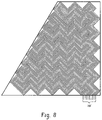
- FIGS. 3-8 are examples of specular conductive patterns 1 - 6 , respectively, suitable for embodying the broad principles of the present invention.
- FIG. 9 is a cross-sectional schematic illustration of a radar altering structure switching apparatus suitable for embodying another aspect of the present invention.
- circuit patterns For military applications, it is well known that structures, such as aircraft surfaces, for example, are designed to operate stealthily against radar illumination.
- an electro-thermal heater element with circuit patterns such as those exemplified in FIG. 2 are applied to the surface of such structures, the heater element circuit patterns alter the radar cross-section of the structure rendering the structure more vulnerable to radar illumination.
- the circuit pattern design of FIG. 2 comprises conductive circuit paths that are substantially transverse to electromagnetic illumination by a point source monostatic radar from the front, the rear or either side. Accordingly, the circuit paths of such patterns create intense reflected electromagnetic waves directly back to the point source radar to magnify the radar cross-section of the structure.
- the radar cross-section altering embodiments of the present invention involve the modification and enhancement of the specular characteristics for the electromagnetic properties of the electro-thermal heater elements to provide additional magnetic and electrical energy loss due to reflective and interference mechanisms.
- this energy loss is designed to occur when an electromagnetic wave of energy is applied by a radar source at a desired frequency of utilization (MHz or GHz) and over a broadband range to maximize absorption of electromagnetic energy by normal or modified conductors of the heater element and dampen the radar signals returned thereby to the radar source.
- the heater elements via conductive paths 16 are electrified by the deicing system 20 as illustrated in FIG. 1 .
- Specular pattern designs 1 - 6 of the various embodiments of the conductive paths of the heater element 10 are shown by way of example in FIGS. 3-8 , respectively.
- round wire may be used for the conductive paths because of its inherent reflective properties to reduce returns from illumination by a point source monostatic radar.
- the conductive paths of the various heater element patterns may be etched foil, metallic coated fabric or the like without deviating from the broad principles of the present invention.
- the preferred application of the heater element patterns is integration into composite non-metallic structures. However, applying the heater element patterns over or under metallic or non-metallic surfaces of a structure will work as a radar altering structure just as well.
- Each of the specular patterns 1 - 6 comprises six (6) conductive paths with a supply lead and return lead for each path, rendering twelve (12) connecting leads for each pattern.
- the connecting leads for each specular pattern 1 - 6 are found in FIGS. 3-8 at 16 a - 16 f , respectively.
- the conductive paths of each of the specular patterns 1 - 4 and 6 start and end in the same vicinity.
- the two outer leads of 16 a in FIG. 3 are the supply and return connector leads of one conductive path, and the next two outer leads going inward are the supply and return connecting leads of another conductive path, and so on.
- the conductive paths are juxtaposed and electrically isolated from one another with one conductive path being circumscribed by another extending outwardly until a final outer conductive path completes the overall pattern.
- the specular pattern 5 of FIG. 7 is slightly different from the others having conductive paths that are juxtaposed and electrically isolated from one another, except that the conductive paths are not circumscribed by each other. Rather, each conductive path starts at one end of the specular pattern and runs back and forth forming a plurality of three sided subpatterns one within the other extending across the overall pattern. Thus, the conductive paths end at the other end of the specular pattern 5 .
- the conductive paths of the specular patterns 1 - 4 and 6 comprise short zig-zag and angular straight line runs of repeating subpatterns which are designed to provide opposing perpendicular lines of electromagnetic reflectance at a forty-five degree (45°) angle with respect to the line of sight a point source monostatic radar creating destructive zones of interference from any unabsorbed electromagnetic waves.
- the specular pattern 5 is different from the others as noted above and comprises larger subpatterns made from conductive paths of longer runs which are wavy line paths and not straight line paths as in specular patterns 1 - 4 and 6 .
- each of the specular patterns 1 - 6 function to reflect the electromagnetic waves away from returning to their source or to create a destructive interference between the electromagnetic waves. In either case, the electromagnetic waves returned to the radar source from the structure are altered in such a way that reduces the radar cross-section of the structure.
- each of the different patterns of conductive paths as exemplified in FIGS. 3-8 is intended to alter the radar cross-sectional area of the structure to which it is applied.
- the specular patterns of conductive paths may be applied to a structure and used as a stealth agent to cloak the structure from enemy radar, i.e. render it substantially transparent to radar.
- a chosen pattern of conductive paths may be integrated into composite material forming a skin of the structure, like an airfoil of an aircraft, for example.
- the structure becomes a radar altering structure (RAS) so that the radar cross-sectional area of the structure is substantially reduced.
- RAS radar altering structure
- a radar altering structure may involve applying one or more patterns of conductive paths to respective portions of the structure and electrifying the conductive paths thereof.
- the pattern of conductive paths may be controlled to create special radar signatures of the structure to illuminating radars.
- the conductive paths 16 of the pattern 10 may be coupled to a RAS switch system 30 as shown in the schematic illustration of FIG. 9 and operated as a special antenna to illuminating radars.
- the system 30 may be operative to connect and disconnect the conductive paths to a voltage source or ground, for example.
- the conductive paths 16 become closed circuits and render the structure transparent to the illuminating radar, and when disconnected, the paths 16 are open-circuits and floating, i.e. ungrounded, and render the structure apparent to the radar. Therefore, the pattern of conductive paths may be controlled by closing and opening the circuits thereof to respond differently to illuminating radar signals, and possibly, send out false radar return signals to mislead the enemy.
Abstract
Description
Claims (21)
Priority Applications (1)
| Application Number | Priority Date | Filing Date | Title |
|---|---|---|---|
| US11/586,892 US7633450B2 (en) | 2005-11-18 | 2006-10-26 | Radar altering structure using specular patterns of conductive material |
Applications Claiming Priority (2)
| Application Number | Priority Date | Filing Date | Title |
|---|---|---|---|
| US73795905P | 2005-11-18 | 2005-11-18 | |
| US11/586,892 US7633450B2 (en) | 2005-11-18 | 2006-10-26 | Radar altering structure using specular patterns of conductive material |
Publications (2)
| Publication Number | Publication Date |
|---|---|
| US20070115163A1 US20070115163A1 (en) | 2007-05-24 |
| US7633450B2 true US7633450B2 (en) | 2009-12-15 |
Family
ID=37547416
Family Applications (1)
| Application Number | Title | Priority Date | Filing Date |
|---|---|---|---|
| US11/586,892 Active US7633450B2 (en) | 2005-11-18 | 2006-10-26 | Radar altering structure using specular patterns of conductive material |
Country Status (5)
| Country | Link |
|---|---|
| US (1) | US7633450B2 (en) |
| CA (1) | CA2566718C (en) |
| DE (1) | DE102006054445A1 (en) |
| FR (1) | FR2893716A1 (en) |
| GB (1) | GB2432409B (en) |
Cited By (4)
| Publication number | Priority date | Publication date | Assignee | Title |
|---|---|---|---|---|
| US20130222171A1 (en) * | 2012-01-12 | 2013-08-29 | Booz, Allen & Hamilton | Radio-frequency (rf) precision nulling device |
| US20140299743A1 (en) * | 2012-11-27 | 2014-10-09 | The Board Of Trustees Of The Leland Stanford Junior University | Universal Linear Components |
| US10284819B2 (en) | 2013-12-02 | 2019-05-07 | Goodrich Corporation | Long-range image reconstruction using measured atmospheric characterization |
| US20210176825A1 (en) * | 2017-12-08 | 2021-06-10 | Misuzu Industry Co., Ltd. | Heater, fixing device, image-forming device, and heating device |
Families Citing this family (3)
| Publication number | Priority date | Publication date | Assignee | Title |
|---|---|---|---|---|
| FR2980458B1 (en) * | 2011-09-28 | 2013-08-30 | Aircelle Sa | LIP ASSEMBLY FOR ELECTRIC DEFROSTING TURBOREACTOR BOOM NACELLE |
| RU2619388C2 (en) * | 2012-08-06 | 2017-05-15 | Воббен Пропертиз Гмбх | Heated rotor blade of wind turbine |
| US11719119B1 (en) * | 2022-03-23 | 2023-08-08 | Rolls-Royce Corporation | Aircraft with ram air turbine disk with generator having blade shroud ring integrated magnets |
Citations (38)
| Publication number | Priority date | Publication date | Assignee | Title |
|---|---|---|---|---|
| GB1047220A (en) | 1959-06-16 | |||
| GB838624A (en) | 1955-05-31 | 1960-06-22 | Rca Corp | An electrical display device |
| US2976184A (en) | 1955-11-28 | 1961-03-21 | Du Pont | Method of coating a polymeric thermoplastic dielectric film and article produced thereby |
| GB1314624A (en) | 1971-04-06 | 1973-04-26 | Barracudaverken Ab | Radar camouflage |
| US3733606A (en) | 1968-04-01 | 1973-05-15 | Barracudaverken Ab | Camouflaging means for preventing or obstructing detection by radar reconnaissance |
| US3763349A (en) | 1972-07-17 | 1973-10-02 | Watlow Electric Manuf Co | Radiant heater with improved radiating bars and mounting means therefor |
| US3887920A (en) | 1961-03-16 | 1975-06-03 | Us Navy | Thin, lightweight electromagnetic wave absorber |
| US4019699A (en) | 1974-04-30 | 1977-04-26 | Teledyne Ryan Aeronautical A Division Of Teledyne Industries, Inc. | Aircraft of low observability |
| GB2038712A (en) | 1978-11-23 | 1980-07-30 | Bienvenu E | Absorbant and/or reflecting shield |
| DE2759657A1 (en) | 1977-11-15 | 1983-09-08 | Pusch, Günter, Dr.-Ing., 6903 Neckargemünd | Heat-insulated camouflage material - screens military targets from radar, ultra-violet, infra-red and visible light using reflective layers |
| DE3507889A1 (en) | 1985-03-06 | 1986-09-11 | Clouth Gummiwerke AG, 5000 Köln | Article provided with a covering |
| DE3830335A1 (en) | 1987-09-24 | 1989-04-27 | Messerschmitt Boelkow Blohm | De-icing device for aircraft |
| EP0362662A1 (en) | 1988-09-30 | 1990-04-11 | Rockwell International Corporation | Electrically heated structural composite and method of its manufacture |
| DE3730435C1 (en) | 1987-09-10 | 1991-02-21 | Gerd Dipl-Wirtsch-Ing Hugo | Laminated heatable radar absorber - has electrically-conducting mutually isolated heating layer surface elements |
| GB2243412A (en) | 1990-03-30 | 1991-10-30 | United Technologies Corp | Aircraft engine propulsor blade deicing |
| US5103371A (en) | 1990-04-20 | 1992-04-07 | Matsushita Electric Industrial Co., Ltd. | Capacitor and process for production thereof |
| US5223849A (en) | 1986-11-25 | 1993-06-29 | Chomerics, Inc. | Broadband electromagnetic energy absorber |
| US5346160A (en) * | 1992-06-30 | 1994-09-13 | The B. F. Goodrich Company | Electro-expulsive deicing system having fail safe conductive bridge means |
| US5398890A (en) | 1992-11-25 | 1995-03-21 | The B. F. Goodrich Company | Pneumatic deicer assembly having a self connecting shell |
| EP0737148A1 (en) | 1993-12-27 | 1996-10-16 | The B.F. Goodrich Company | Variable power density heating using stranded resistance wire |
| US5657951A (en) | 1995-06-23 | 1997-08-19 | The B.F. Goodrich Company | Electrothermal de-icing system |
| US5717397A (en) | 1996-05-17 | 1998-02-10 | Lockheed Martin Corporation | Low observable shape conversion for aircraft weaponry |
| US5837739A (en) | 1995-06-07 | 1998-11-17 | Mcdonnell Douglas Corporation | Loaded syntactic foam-core material |
| US5866273A (en) | 1990-03-20 | 1999-02-02 | The Boeing Company | Corrosion resistant RAM powder |
| WO2001008973A1 (en) | 1999-07-30 | 2001-02-08 | Northcoast Technologies | Zoned aircraft de-icing system and method |
| WO2001043507A1 (en) | 1999-12-10 | 2001-06-14 | Thermion Systems International | A thermoplastic laminate fabric heater and methods for making same |
| US6318667B1 (en) | 1999-03-31 | 2001-11-20 | Raymond C. Morton | Stealth weapon systems |
| WO2002032189A1 (en) | 2000-10-12 | 2002-04-18 | Goodrich Corporation | Electrically heated aircraft deicer panel |
| US6402093B1 (en) | 2000-07-13 | 2002-06-11 | Lockheed Martin Corporation | Method and apparatus for autonomous de-icing |
| US6624359B2 (en) | 2001-12-14 | 2003-09-23 | Neptco Incorporated | Multifolded composite tape for use in cable manufacture and methods for making same |
| WO2003095729A1 (en) | 2002-05-10 | 2003-11-20 | Sarnoff Corporation | Plural layer woven electronic textile, article and method |
| WO2003100364A2 (en) | 2002-05-23 | 2003-12-04 | Bell Helicopter Textron Inc. | Method and apparatus for reducing the infrared and radar signature of a vehicle |
| US20050067532A1 (en) * | 2003-09-25 | 2005-03-31 | Hindel James T. | Radar absorbing electrothermal de-icer |
| US6951985B1 (en) | 1995-05-08 | 2005-10-04 | Lemelson Jerome H | Superconducting electrical cable |
| EP1604908A2 (en) | 1995-06-06 | 2005-12-14 | Ghaleb Mohamad Yassin Alhamed | Method for protection of a fuel tank or a vehicle against a focused beam of radiant energy |
| EP1703247A1 (en) | 2005-03-14 | 2006-09-20 | Bacam | Infrared shielding and radar attenuating textile material |
| US20060227056A1 (en) | 2005-04-04 | 2006-10-12 | Brittingham David L | Electrothermal deicing apparatus and a dual function heater conductor for use therein |
| GB2428275A (en) | 2005-07-14 | 2007-01-24 | Goodrich Corp | Aircraft engine nacelle ice protection system |
-
2006
- 2006-10-26 US US11/586,892 patent/US7633450B2/en active Active
- 2006-10-31 CA CA2566718A patent/CA2566718C/en not_active Expired - Fee Related
- 2006-11-06 GB GB0622087A patent/GB2432409B/en not_active Expired - Fee Related
- 2006-11-16 DE DE102006054445A patent/DE102006054445A1/en not_active Withdrawn
- 2006-11-17 FR FR0610082A patent/FR2893716A1/en active Pending
Patent Citations (38)
| Publication number | Priority date | Publication date | Assignee | Title |
|---|---|---|---|---|
| GB838624A (en) | 1955-05-31 | 1960-06-22 | Rca Corp | An electrical display device |
| US2976184A (en) | 1955-11-28 | 1961-03-21 | Du Pont | Method of coating a polymeric thermoplastic dielectric film and article produced thereby |
| GB1047220A (en) | 1959-06-16 | |||
| US3887920A (en) | 1961-03-16 | 1975-06-03 | Us Navy | Thin, lightweight electromagnetic wave absorber |
| US3733606A (en) | 1968-04-01 | 1973-05-15 | Barracudaverken Ab | Camouflaging means for preventing or obstructing detection by radar reconnaissance |
| GB1314624A (en) | 1971-04-06 | 1973-04-26 | Barracudaverken Ab | Radar camouflage |
| US3763349A (en) | 1972-07-17 | 1973-10-02 | Watlow Electric Manuf Co | Radiant heater with improved radiating bars and mounting means therefor |
| US4019699A (en) | 1974-04-30 | 1977-04-26 | Teledyne Ryan Aeronautical A Division Of Teledyne Industries, Inc. | Aircraft of low observability |
| DE2759657A1 (en) | 1977-11-15 | 1983-09-08 | Pusch, Günter, Dr.-Ing., 6903 Neckargemünd | Heat-insulated camouflage material - screens military targets from radar, ultra-violet, infra-red and visible light using reflective layers |
| GB2038712A (en) | 1978-11-23 | 1980-07-30 | Bienvenu E | Absorbant and/or reflecting shield |
| DE3507889A1 (en) | 1985-03-06 | 1986-09-11 | Clouth Gummiwerke AG, 5000 Köln | Article provided with a covering |
| US5223849A (en) | 1986-11-25 | 1993-06-29 | Chomerics, Inc. | Broadband electromagnetic energy absorber |
| DE3730435C1 (en) | 1987-09-10 | 1991-02-21 | Gerd Dipl-Wirtsch-Ing Hugo | Laminated heatable radar absorber - has electrically-conducting mutually isolated heating layer surface elements |
| DE3830335A1 (en) | 1987-09-24 | 1989-04-27 | Messerschmitt Boelkow Blohm | De-icing device for aircraft |
| EP0362662A1 (en) | 1988-09-30 | 1990-04-11 | Rockwell International Corporation | Electrically heated structural composite and method of its manufacture |
| US5866273A (en) | 1990-03-20 | 1999-02-02 | The Boeing Company | Corrosion resistant RAM powder |
| GB2243412A (en) | 1990-03-30 | 1991-10-30 | United Technologies Corp | Aircraft engine propulsor blade deicing |
| US5103371A (en) | 1990-04-20 | 1992-04-07 | Matsushita Electric Industrial Co., Ltd. | Capacitor and process for production thereof |
| US5346160A (en) * | 1992-06-30 | 1994-09-13 | The B. F. Goodrich Company | Electro-expulsive deicing system having fail safe conductive bridge means |
| US5398890A (en) | 1992-11-25 | 1995-03-21 | The B. F. Goodrich Company | Pneumatic deicer assembly having a self connecting shell |
| EP0737148A1 (en) | 1993-12-27 | 1996-10-16 | The B.F. Goodrich Company | Variable power density heating using stranded resistance wire |
| US6951985B1 (en) | 1995-05-08 | 2005-10-04 | Lemelson Jerome H | Superconducting electrical cable |
| EP1604908A2 (en) | 1995-06-06 | 2005-12-14 | Ghaleb Mohamad Yassin Alhamed | Method for protection of a fuel tank or a vehicle against a focused beam of radiant energy |
| US5837739A (en) | 1995-06-07 | 1998-11-17 | Mcdonnell Douglas Corporation | Loaded syntactic foam-core material |
| US5657951A (en) | 1995-06-23 | 1997-08-19 | The B.F. Goodrich Company | Electrothermal de-icing system |
| US5717397A (en) | 1996-05-17 | 1998-02-10 | Lockheed Martin Corporation | Low observable shape conversion for aircraft weaponry |
| US6318667B1 (en) | 1999-03-31 | 2001-11-20 | Raymond C. Morton | Stealth weapon systems |
| WO2001008973A1 (en) | 1999-07-30 | 2001-02-08 | Northcoast Technologies | Zoned aircraft de-icing system and method |
| WO2001043507A1 (en) | 1999-12-10 | 2001-06-14 | Thermion Systems International | A thermoplastic laminate fabric heater and methods for making same |
| US6402093B1 (en) | 2000-07-13 | 2002-06-11 | Lockheed Martin Corporation | Method and apparatus for autonomous de-icing |
| WO2002032189A1 (en) | 2000-10-12 | 2002-04-18 | Goodrich Corporation | Electrically heated aircraft deicer panel |
| US6624359B2 (en) | 2001-12-14 | 2003-09-23 | Neptco Incorporated | Multifolded composite tape for use in cable manufacture and methods for making same |
| WO2003095729A1 (en) | 2002-05-10 | 2003-11-20 | Sarnoff Corporation | Plural layer woven electronic textile, article and method |
| WO2003100364A2 (en) | 2002-05-23 | 2003-12-04 | Bell Helicopter Textron Inc. | Method and apparatus for reducing the infrared and radar signature of a vehicle |
| US20050067532A1 (en) * | 2003-09-25 | 2005-03-31 | Hindel James T. | Radar absorbing electrothermal de-icer |
| EP1703247A1 (en) | 2005-03-14 | 2006-09-20 | Bacam | Infrared shielding and radar attenuating textile material |
| US20060227056A1 (en) | 2005-04-04 | 2006-10-12 | Brittingham David L | Electrothermal deicing apparatus and a dual function heater conductor for use therein |
| GB2428275A (en) | 2005-07-14 | 2007-01-24 | Goodrich Corp | Aircraft engine nacelle ice protection system |
Non-Patent Citations (3)
| Title |
|---|
| International Search Report and Written Opinion dated Oct. 11, 2006 from PCT/US2006/12973. |
| Search Report for GB 0622087.5 dated May 23, 2007, mailed May 24, 2007. |
| Search Report for GB0622087.5, dated Feb. 8, 2007, mailed Feb. 9, 2007. |
Cited By (5)
| Publication number | Priority date | Publication date | Assignee | Title |
|---|---|---|---|---|
| US20130222171A1 (en) * | 2012-01-12 | 2013-08-29 | Booz, Allen & Hamilton | Radio-frequency (rf) precision nulling device |
| US20140299743A1 (en) * | 2012-11-27 | 2014-10-09 | The Board Of Trustees Of The Leland Stanford Junior University | Universal Linear Components |
| US10534189B2 (en) * | 2012-11-27 | 2020-01-14 | The Board Of Trustees Of The Leland Stanford Junior University | Universal linear components |
| US10284819B2 (en) | 2013-12-02 | 2019-05-07 | Goodrich Corporation | Long-range image reconstruction using measured atmospheric characterization |
| US20210176825A1 (en) * | 2017-12-08 | 2021-06-10 | Misuzu Industry Co., Ltd. | Heater, fixing device, image-forming device, and heating device |
Also Published As
| Publication number | Publication date |
|---|---|
| DE102006054445A1 (en) | 2007-05-24 |
| CA2566718C (en) | 2013-05-28 |
| US20070115163A1 (en) | 2007-05-24 |
| GB2432409B (en) | 2010-09-15 |
| GB2432409A (en) | 2007-05-23 |
| CA2566718A1 (en) | 2007-05-18 |
| GB0622087D0 (en) | 2006-12-13 |
| FR2893716A1 (en) | 2007-05-25 |
Similar Documents
| Publication | Publication Date | Title |
|---|---|---|
| US7633450B2 (en) | Radar altering structure using specular patterns of conductive material | |
| EP1866202B1 (en) | Electrothermal deicing apparatus and a dual function heater conductor for use therein | |
| US4999639A (en) | Radome having integral heating and impedance matching elements | |
| US6636182B2 (en) | Structural antenna for flight aggregates or aircraft | |
| Singh et al. | Active radar cross section reduction | |
| CN102026531A (en) | Super-matching wave-absorbing material formed by utilizing sheeted cross-shaped metal unit structure | |
| US9778000B2 (en) | Off-board influence system | |
| CN110854544B (en) | Low-RCS phased-array antenna and RCS reduction method | |
| JP2016030584A (en) | Antenna cover of aircraft, cover for component of aircraft, aircraft, and rain erosion boot for aircraft | |
| CN109638456B (en) | Phased array RCS reduction method based on scattering phase reconstruction | |
| US11031685B2 (en) | Aircraft radomes with broadband transparency | |
| US5276447A (en) | Radar echo reduction device | |
| GB2461329A (en) | Controllable transponder | |
| CN104901018B (en) | A kind of panel with counter radar detecting function | |
| WO2021022883A1 (en) | Meta-material, de-icing device, and aircraft | |
| Pinto et al. | Radar signature reduction of wind turbines through the application of stealth technology | |
| CN210956948U (en) | Metamaterial, deicing device, radar cover and aircraft | |
| CN106299720A (en) | Meta Materials, eyelid covering and aircraft | |
| CN111384592B (en) | Antenna device and radar | |
| JP2007110330A (en) | Array antenna | |
| US6184815B1 (en) | Transmission line electromagnetic reflection reduction treatment | |
| WO2021022884A1 (en) | Metamaterial, radome and aircraft | |
| CN102606384A (en) | Rotor blade for a wind turbine, and a combination of a radar station and a wind turbine | |
| Yashno et al. | Multichannel metagrating diffusers for broad-angle radar cross section (RCS) reduction | |
| Wang et al. | Reconfigurable radar absorbing structure applied to the antenna radar cross section reduction |
Legal Events
| Date | Code | Title | Description |
|---|---|---|---|
| AS | Assignment |
Owner name: GOODRICH CORPORATION, NORTH CAROLINA Free format text: ASSIGNMENT OF ASSIGNORS INTEREST;ASSIGNORS:BRITTINGHAM, DAVID L.;HINDEL, JAMES T.;REEL/FRAME:018890/0459 Effective date: 20061019 |
|
| STCF | Information on status: patent grant |
Free format text: PATENTED CASE |
|
| CC | Certificate of correction | ||
| FPAY | Fee payment |
Year of fee payment: 4 |
|
| FPAY | Fee payment |
Year of fee payment: 8 |
|
| MAFP | Maintenance fee payment |
Free format text: PAYMENT OF MAINTENANCE FEE, 12TH YEAR, LARGE ENTITY (ORIGINAL EVENT CODE: M1553); ENTITY STATUS OF PATENT OWNER: LARGE ENTITY Year of fee payment: 12 |