US7654296B2 - Grooved single facer belt - Google Patents
Grooved single facer belt Download PDFInfo
- Publication number
- US7654296B2 US7654296B2 US10/720,902 US72090203A US7654296B2 US 7654296 B2 US7654296 B2 US 7654296B2 US 72090203 A US72090203 A US 72090203A US 7654296 B2 US7654296 B2 US 7654296B2
- Authority
- US
- United States
- Prior art keywords
- grooves
- combination
- belt
- base structure
- polymeric resin
- Prior art date
- Legal status (The legal status is an assumption and is not a legal conclusion. Google has not performed a legal analysis and makes no representation as to the accuracy of the status listed.)
- Expired - Fee Related, expires
Links
Images


Classifications
-
- B—PERFORMING OPERATIONS; TRANSPORTING
- B31—MAKING ARTICLES OF PAPER, CARDBOARD OR MATERIAL WORKED IN A MANNER ANALOGOUS TO PAPER; WORKING PAPER, CARDBOARD OR MATERIAL WORKED IN A MANNER ANALOGOUS TO PAPER
- B31F—MECHANICAL WORKING OR DEFORMATION OF PAPER, CARDBOARD OR MATERIAL WORKED IN A MANNER ANALOGOUS TO PAPER
- B31F1/00—Mechanical deformation without removing material, e.g. in combination with laminating
- B31F1/20—Corrugating; Corrugating combined with laminating to other layers
- B31F1/24—Making webs in which the channel of each corrugation is transverse to the web feed
- B31F1/26—Making webs in which the channel of each corrugation is transverse to the web feed by interengaging toothed cylinders cylinder constructions
- B31F1/28—Making webs in which the channel of each corrugation is transverse to the web feed by interengaging toothed cylinders cylinder constructions combined with uniting the corrugated webs to flat webs ; Making double-faced corrugated cardboard
- B31F1/2845—Details, e.g. provisions for drying, moistening, pressing
- B31F1/2877—Pressing means for bringing facer sheet and corrugated webs into contact or keeping them in contact, e.g. rolls, belts
-
- Y—GENERAL TAGGING OF NEW TECHNOLOGICAL DEVELOPMENTS; GENERAL TAGGING OF CROSS-SECTIONAL TECHNOLOGIES SPANNING OVER SEVERAL SECTIONS OF THE IPC; TECHNICAL SUBJECTS COVERED BY FORMER USPC CROSS-REFERENCE ART COLLECTIONS [XRACs] AND DIGESTS
- Y10—TECHNICAL SUBJECTS COVERED BY FORMER USPC
- Y10T—TECHNICAL SUBJECTS COVERED BY FORMER US CLASSIFICATION
- Y10T428/00—Stock material or miscellaneous articles
- Y10T428/24—Structurally defined web or sheet [e.g., overall dimension, etc.]
- Y10T428/24479—Structurally defined web or sheet [e.g., overall dimension, etc.] including variation in thickness
- Y10T428/2457—Parallel ribs and/or grooves
Definitions
- the present invention relates to corrugated paper board manufacture and to the belts required by the machines used to manufacture that variety of paper board. More specifically, the present invention relates to the belts that may be used on the single-facer section of a corrugated board production line.
- a so-called core paper is heated by steam, which makes it more pliable, and is then fed into a nip formed between a pair of toothed rollers whose teeth mesh, thereby corrugating the core paper in a uniform, undulating pattern.
- Starch paste is subsequently applied to the crests of the corrugated core paper, which is then mated to a liner paper in a press nip. There, the corrugated core paper and liner paper are bonded together to form a completed sheet, which can then be further processed as desired.
- the press nip is formed by one of the toothed or corrugating rolls and a pressure roll.
- the press nip is extended in the running direction through the use of a belt instead of a pressure roll.
- the belt holds the corrugated core paper and liner paper together against the corrugating roll for a significant portion of its circumference.
- the belt experiences severe operating conditions. Because heat is used to vaporize moisture in the core paper, the belt operates in a high-temperature environment and under high tension. Further, the belt continually runs against the teeth on the corrugating roll albeit with the sheet in between the belt and roll to develop the required bonding pressure between the core paper and the liner paper. Moreover, the belt must be flexible yet have lengthwise strength and widthwise rigidity sufficient to withstand wrinkling, which may cause the belt to drift undesirably from side to side.
- the belt faces two opposing problems. Initially, it is necessary that the belt have a sufficient coefficient of friction that the liner paper can be drawn into the nip by the belt and attached to the core paper. As a result there have been several solutions proposed for increasing the coefficient of friction on the surface of the belt including coating the belt with resins, needling fibers into the belt, and a combination of both of these procedures, as discussed in commonly assigned U.S. Pat. Nos. 6,470,944 and 6,276,420, both of which are incorporated herein by reference.
- both of these solutions increase the coefficient of friction sufficient to enable the belt to draw the liner paper into the nip, in certain instances they may create an opposing problem as the paper exits the nip in that the coefficient of friction can be so great that the bonded core and liner papers are drawn in the direction of travel of the belt. This results in decreased quality of the corrugated board. Accordingly, there is a need for a corrugator belt that has the ability to adequately vent moisture from the board, release the board cleanly after the nip, and has a sufficiently high coefficient of friction that the liner paper can be drawn into the nip.
- the present invention provides an improvement and/or solution to the problems inherent in the use of a belt of the foregoing varieties.
- the present invention relates to a single facer corrugator belt having a base structure.
- the base structure includes an inside and an outside surface and a machine or running direction and a cross machine direction.
- the base structure is formed by machine direction yarns and cross machine direction yarns and has grooves formed in the coated outside surface of the base structure.
- the present invention is also directed to a single facer corrugator belt having a base structure.
- the base structure has an inside and an outside surface and a machine or running direction and a cross machine direction.
- the base structure is preferably formed by machine direction yarns and cross machine direction yarns, and after coating includes means formed in the coated outside surface of the structure to remove moisture.
- FIG. 1 shows a typical belted single-facer corrugated board production line
- FIG. 2 is a perspective view of a belt according to one embodiment of the present invention.
- FIG. 3 is a cross sectional view of the belt shown in FIG. 2 taken along line 3 - 3 with a impermeable resin layer;
- FIG. 4 is a cross sectional view of the belt shown in FIG. 2 taken along line 3 - 3 with a permeable resin layer;
- FIG. 5 is a cross sectional view of the belt shown in FIG. 2 taken along line 3 - 3 with an impermeable resin layer and having needled fibers;
- FIG. 6 is a cross sectional view of the belt shown in FIG. 2 taken along line 3 - 3 with a permeable resin layer and having needled fibers;
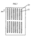
- FIGS. 7-14 are top views showing alternative groove patterns in both the longitudinal and transverse directions according to the present invention.
- FIGS. 15-20 are cross-sectional views of groove patterns formed in a belt according to the present invention.
- FIG. 1 is a schematic view of a typical belted single-facer section 10 of a corrugated board production line.
- a core paper 12 previously exposed to steam, which makes it more pliable, is fed continuously between a pair of cooperating rolls 14 , 16 .
- the rolls 14 , 16 have uniformly spaced, peripheral teeth 18 , 20 , which mesh as the rolls 14 , 16 rotate about their respective, parallel axes 22 , 24 .
- the meshing teeth 18 , 20 produce corrugations 26 in the core paper 12 .
- a coating mechanism 28 applies a starch paste 30 to the crests 32 of the corrugations 26 in the core paper 12 .
- the corrugated core paper 12 is continuously applied to a liner paper 34 at point 36 , where a belt 40 , which is trained around a pair of spaced rollers 42 , 44 , passes around roller 42 .
- the spaced rollers 42 , 44 are so disposed that belt 40 bears against roll 16 , and both may form nips with roll 16 , so that the belt 40 , trained thereabout, bears against roll 16 for the entire interval between spaced rollers 42 , 44 forming an extended nip between roll 16 and belt 40 .
- Heat is applied to the corrugated core paper 12 and liner paper 34 through at least one of the rollers 42 , 44 , belt 40 and roll 16 . The heat vaporizes water absorbed by the corrugated core paper 12 when the corrugated core paper 12 was exposed to steam and dries the starch paste 30 .
- the rollers 42 , 44 are situated so that the teeth 20 on roll 16 bear against the outside surface of the belt 40 over a substantial circumferential extent as the system operates.
- the teeth 20 maintain the proper registration of the corrugated core paper 12 as it is advanced.
- the roll 16 firmly presses the side of the core paper 12 with the paste thereon against the liner paper 34 to effect bonding there between.
- the corrugated core paper 12 with the liner paper 34 attached thereto exits as a completed product 50 from between the roll 16 and the roller 44 .
- FIG. 2 A perspective view of the belt 40 is provided in FIG. 2 .
- the belt 40 has an inner surface 60 and an outer surface 62 .
- the outer surface 62 is provided with a plurality of grooves 64 extending substantially in the machine direction around the belt 40 .
- FIG. 3 is a cross section of belt 40 taken as indicated by line 3 - 3 in FIG. 2 .
- the cross section is taken in the transverse, or cross-machine, direction of belt, and shows that belt includes a base structure 66 .
- the base structure 66 may be woven from transverse, or cross-machine direction, yarns 68 and longitudinal, or machine-direction, yarns 70 .
- Base structure 66 is depicted as having been woven flat, the transverse yarns 68 being weft yarns weaving over, under and between the stacked pairs of longitudinal warp yarns 70 in a duplex weave and joined to form an endless belt. It should be understood, however, that base structure 66 may be woven endless. It should be further understood that base structure 66 may be woven in a single-layer weave, or in any other weave suitable for the purpose.
- the base structure 66 may alternatively be a non-woven structure in the form of, for example, a mesh as in an assembly of transverse and longitudinal yarns, which may be bonded together at their mutual crossing points to form a fabric. Further, the base structure 66 may be a knitted or braided fabric, or a spiral-link belt of the type shown in U.S. Pat. No. 4,567,077 to Gauthier, the teachings of which are incorporated herein by reference. The base structure 66 may also be extruded from a polymeric resin material in the form of a sheet or membrane, which may subsequently be provided with apertures.
- the base structure 66 may comprise non-woven mesh fabrics, such as those shown in commonly assigned U.S. Pat. No. 4,427,734 to Johnson, the teachings of which are incorporated herein by reference.
- the base structure 66 may be produced by spirally winding a strip of woven, non-woven, knitted, mesh, or braided according to the methods shown in commonly assigned U.S. Pat. No. 5,360,656 to Rexfelt et al., the teachings of which are incorporated herein by reference.
- the base structure 66 may accordingly comprise a spirally wound strip, wherein each spiral turn is joined to the next by a continuous seam making the base structure endless in a longitudinal direction.
- a belt 40 having a base structure 66 of this type is disclosed in commonly assigned U.S. Pat. Nos. 5,792,323 and 5,837,080, the teachings of which are incorporated herein by reference.
- One or more layers of this type can be utilized, again a seam optionally may be introduced for installation on the machine.
- the base structure 66 may be woven, or otherwise assembled, from warp yarns and weft yarns comprising yarns of any of the varieties used in the manufacture of paper machine clothing and industrial process fabrics. That is to say, the base structure 66 may include natural or metal yarns, monofilament, plied monofilament, multifilament, plied multifilament or yarns spun from staple fibers of any of the synthetic polymeric resins used by those skilled in the art in the manufacture of fabrics intended for use in high-temperature environments.
- the base structure 66 may be manufactured from yarns of the following materials: polyaramids, such as Nomex®, and Kevlar®; polyphenylene sulfide (PPS), which is more commonly known as Ryton®; an aromatic polyester, which is commonly known as VECTRAN®; polyetheretherketone (PEEK); polyester and blends thereof.
- the base structure may comprise yarns of Kevlar® in the machine direction and Ryton® or polyester monofilament yarns in the cross-machine direction.
- the outer surface 62 of belt 40 that is, the surface which contacts the board may be formed by a polymeric resin coating 82 , as shown in FIGS. 3 and 4 .
- the inner surface 60 of belt 40 that is, the surface which slides over rollers 42 and 44 may also be formed by a polymeric resin coating, not shown.
- the entire structure may be impregnated with resin applied from the outer surface 62 under pressure and forced through the structure such that sufficient resin resides on the sheet contact surface so that the grooves can be formed in said surface.
- the belt 40 may be permeable or impermeable.
- grooves 64 can be cut into the polymeric resin coating and either have sufficient depth to extend past the depth of the resin coating 82 and into the base structure 66 , as shown in FIG. 4 .
- the grooves of belt 40 can have a depth less than the thickness of the resin coating 82 to insure that the resin coating remains impermeable to fluid, as shown in FIG. 3 .
- a land area 65 separates the grooves from one another.
- the grooves 64 and land areas 65 may be of substantially equivalent widths, however, in the preferred embodiment the grooves are narrower than the land width, as shown in FIGS. 3 and 4 .
- the grooves 64 may be provided by cutting a continuous single groove that spirals about the endless loop of the belt on the outer surface.
- the orientation of the resulting grooves 64 may deviate from the machine or longitudinal direction by a small angle.
- the provision of grooves 64 in this manner is contemplated by the inventor as falling within the scope of the invention.
- grooves 64 may alternatively be provided by cutting two continuous grooves which spiral about the endless loop of the belt 40 on outer surface 62 in opposite directions, that is, one describing a right-handed spiral and the other describing a left-handed spiral. Further, the grooves 64 need not be perfectly straight but may have some degree of curvature or waviness, or longitudinal direction by deviating no more than 45 degrees from there at any point, so long as they remain primarily oriented in the machine.
- grooves 64 need not be continuous in their longitudinal direction which may correspond to the machine direction of the belt. Rather, grooves 64 may have a length less than the length of the belt 40 , such as approximately 1 of the length of the belt.
- grooves 64 may vary in accordance with the efficiency of the moisture removal and release characteristics.
- FIGS. 7-14 illustrate several arrangements of grooves.
- grooves 64 may be arranged in a equal number of rows wherein a line intersecting the ends of each groove in a row is substantially perpendicular to the longitudinal direction 100 .
- the number of grooves in a row and distances between adjacent rows in the longitudinal direction on belt 40 may vary in accordance with the application, and/or the desired efficiency of the dewatering process.
- Grooves 64 are separated from one another by the land areas 65 .
- FIG. 8 is a top view of a belt 40 in accordance with another embodiment of the present invention.
- grooves 64 are formed in rows in the longitudinal direction of belt 40 , in which a line intersecting the ends of each groove in a row is at an angle ⁇ to the transverse direction.
- Angle ⁇ may be 25-30°.
- FIG. 9 is a top view of a belt 40 in accordance with another embodiment of the present invention.
- grooves 64 are formed in staggered rows.
- the length of groove 64 in the machine direction may be any length. Further, grooves 64 and land areas 65 may be arranged in any pattern that provides desirable moisture removal and release characteristics. Grooves 64 and land areas 65 are depicted in FIGS. 7-9 as being of different widths, although this need not be the case. Nevertheless, land areas 65 may be thought of as narrow pillars of cured polymeric resin aligned in the machine direction on outer surface 62 of the belt 40 .
- the grooves have been described as running in a longitudinal or machine direction, the present invention is not so limited. That is, the grooves could be arranged in any other direction, such as in a transverse or CD direction, or in a direction which is at an angle ⁇ (such as 0 ⁇ 90°) relative to the machine direction. In such situation, the “length” may be shorter than sides of the belt 40 . Accordingly, the pattern of grooves 64 disclosed in FIGS. 7-9 may be applied to grooves running in these other directions as, for example, shown in FIGS. 10 and 11 .
- grooves 64 may be arranged in a number of columns wherein a line intersecting the ends of each groove in a column is substantially perpendicular to the transverse direction.
- the number of grooves in a column and distances between adjacent columns in the CD or transverse direction on belt 40 may vary in accordance with the application and/or the desired efficiency of the dewatering process.
- grooves 64 may be formed in a staggered pattern, such as in belt 40 shown in FIG. 11 .
- the grooves 64 may be continuous in length in the transverse or CD direction, that is, such grooves may extend transversely from a first position located at or close to a first edge of the belt to a second position located at or close to the opposite edge of the belt.
- the present belt may have other patterns of non-continuous grooves.
- the present belt may have a number of first grooves (such as groove 102 ) and/or a number of second grooves (such as groove 104 ). Each of such grooves may have an overall length and width that is less than the borders of the belt 40 .
- the present belt may have a plurality of grooves oriented in a first direction (such as the MD direction) wherein a number of such grooves are non-continuous grooves and a number of such grooves are continuous grooves.
- a belt 40 according to the present invention may include non-standard type continuous grooves.
- a belt 40 may have a number of continuous grooves 64 each having a straight portion followed by a zigzag portion 110 followed by another straight portion 64 and so forth.
- a belt 40 may have one or more grooves 64 each having a number of first portions 106 having a first width and a number of second portions 108 having a second width that is smaller than the first width.
- the present belt may have any other pattern or combination of continuous and/or non-continuous grooves oriented in any one or more directions wherein all or a relevant portion thereof is shorter than the borders of the arcuate pressure shoe.
- each groove is primarily utilized for moisture removal and release.
- the actual spacing, size, shape and/or depth of each groove may be determined by the desired characteristic.
- the shapes of the grooves utilized in the present belt may have a number of different cross-sectional shapes. Examples of several of such cross-sectional shapes are shown in FIGS. 15-20 .
- the shapes of the grooves of the present belt are not limited to these shapes.
- the base structure 66 may be needled with a web 72 of staple fiber material in such a manner that some of the fibers are driven into the base structure as shown in FIGS. 5 and 6 .
- One or more layers of staple fiber material may be needled into the base structure 66 , and the web 72 may extend partially or completely there through.
- the web 72 of staple fiber material may also form a layer covering a surface of the base structure 66 .
- the web is included in only a portion of FIGS. 5 and 6 .
- the needled base structure may include grooves 64 and an impermeable resin layer 65 .
- the resin layer may be permeable having grooves formed to the depth of the resin layer as shown in FIG. 6 .
- the staple fiber material needled into the base structure 66 may be any of the synthetic polymeric resins used by those skilled in the art in the manufacture of fabrics intended for use in high-temperature environments.
- the staple fiber material may comprise staple fibers of any of the following materials: polyaramids, such as Nomex® and Kevlar®; polyphenylene sulfide (PPS), which is more commonly known as Ryton®; polyetheretherketone (PEEK); and polyester.
- the integrity and durability of the needled belt may be further improved by coating the base structure 66 with a polymeric resin material 82 .
- the coating can provide a structure that is either impermeable or permeable.
- Coating materials include polymeric resins such polyurethane, polyethylene, polyamide, polyvinyl chloride, and ionomer resins sold under the trade name SURLYN®, those of skill in the art will understand that other resin materials could be used provided they provide sufficient frictional coefficients and impermeability to fluids.
- the grooves 64 may be formed into the outer surface 62 of the belt 40 that has been needled with fibers 72 . If the belt is coated with a resin, and after it is cured, the grooves 64 can be cut to either have sufficient depth to extend past the depth of the resin coating and into the base structure 66 , or can be formed to a depth less than the thickness of the resin coating to insure that the resin coating remains impermeable to water. Alternatively, the resin may be impregnated into the base structure 66 of the belt 40
- grooves 64 may be pressed into the outer surface 62 by an embossing device before the polymeric resin 82 has been cured, or may be molded into the belt 40 where it is manufactured using a molding process.
- a series of holes or vents could be drilled into the belt 40 .
- These holes can be used in conjunction with any of the base structures 66 described herein.
- the holes can be formed to a depth equal to or greater than the thickness of the resin layer thus forming a permeable resin layer.
- the belt 40 may include fibers needled into the base to form a fibrous web according to the teachings of the grooved belt embodiments above.
- the holes can be formed to extend completely through the belt 40 whether formed with a permeable layer or impregnated with resin to form a substantially impermeable belt 40 .
- both needled and un-needled resin coated or impregnated belts can be manufactured with grooves or holes and result in superior separation of the belt 40 from the completed corrugated board, resulting in increased quality in the production of corrugated board.
- the resin layer may alternatively be permeable or impermeable depending upon the depth of the grooves and the application of the resin.
- a vented surface having either grooves or holes operates to remove moisture from the corrugated board. In the case of continuous grooves the moisture is vented directly to the atmosphere. In the case of discontinuous grooves or holes, these features act as temporary storage facilities that release the moisture to the atmosphere when outside the nip. So it should be understood that the surface 62 of the belt 40 is multifunctional in that it optimizes moisture venting and removal and provides for smooth sheet release after the nip.
Abstract
Description
Claims (16)
Priority Applications (13)
| Application Number | Priority Date | Filing Date | Title |
|---|---|---|---|
| US10/720,902 US7654296B2 (en) | 2003-11-24 | 2003-11-24 | Grooved single facer belt |
| MXPA06005877A MXPA06005877A (en) | 2003-11-24 | 2004-09-23 | Grooved single facer corrugator belt. |
| EP04784895.7A EP1697118B1 (en) | 2003-11-24 | 2004-09-23 | Grooved single facer corrugator belt |
| AU2004297155A AU2004297155A1 (en) | 2003-11-24 | 2004-09-23 | Grooved single facer corrugator belt |
| CA2546374A CA2546374C (en) | 2003-11-24 | 2004-09-23 | Grooved single facer belt |
| RU2006117330/12A RU2356739C2 (en) | 2003-11-24 | 2004-09-23 | Grooved belt for corrugating machine for manufacturing double-layered corrugated cardboard |
| PCT/US2004/031236 WO2005056281A1 (en) | 2003-11-24 | 2004-09-23 | Grooved single facer corrugator belt |
| JP2006541136A JP4674867B2 (en) | 2003-11-24 | 2004-09-23 | Single-sided belt with grooves |
| KR1020067012595A KR20060111614A (en) | 2003-11-24 | 2004-09-23 | Grooved single facer corrugator belt |
| BRPI0416413-0A BRPI0416413B1 (en) | 2003-11-24 | 2004-09-23 | SINGLE FACE CORRUGATION BELT |
| CNA2004800347562A CN1886252A (en) | 2003-11-24 | 2004-09-23 | Grooved single facer corrugator belt |
| TW093129577A TWI331562B (en) | 2003-11-24 | 2004-09-30 | Grooved single facer belt |
| NO20062976A NO20062976L (en) | 2003-11-24 | 2006-06-26 | Grooved single-sided corrugated belt |
Applications Claiming Priority (1)
| Application Number | Priority Date | Filing Date | Title |
|---|---|---|---|
| US10/720,902 US7654296B2 (en) | 2003-11-24 | 2003-11-24 | Grooved single facer belt |
Publications (2)
| Publication Number | Publication Date |
|---|---|
| US20050112332A1 US20050112332A1 (en) | 2005-05-26 |
| US7654296B2 true US7654296B2 (en) | 2010-02-02 |
Family
ID=34591677
Family Applications (1)
| Application Number | Title | Priority Date | Filing Date |
|---|---|---|---|
| US10/720,902 Expired - Fee Related US7654296B2 (en) | 2003-11-24 | 2003-11-24 | Grooved single facer belt |
Country Status (13)
| Country | Link |
|---|---|
| US (1) | US7654296B2 (en) |
| EP (1) | EP1697118B1 (en) |
| JP (1) | JP4674867B2 (en) |
| KR (1) | KR20060111614A (en) |
| CN (1) | CN1886252A (en) |
| AU (1) | AU2004297155A1 (en) |
| BR (1) | BRPI0416413B1 (en) |
| CA (1) | CA2546374C (en) |
| MX (1) | MXPA06005877A (en) |
| NO (1) | NO20062976L (en) |
| RU (1) | RU2356739C2 (en) |
| TW (1) | TWI331562B (en) |
| WO (1) | WO2005056281A1 (en) |
Families Citing this family (11)
| Publication number | Priority date | Publication date | Assignee | Title |
|---|---|---|---|---|
| ITMI20050123A1 (en) * | 2005-01-28 | 2006-07-29 | Feltri Marone S P A | CORRUGATOR BELT SUPPORT-TRANSPORT OF CORRUGATED CARDBOARD IN A WAVING MACHINE |
| JP4477025B2 (en) * | 2007-03-12 | 2010-06-09 | イチカワ株式会社 | Shoe press belt for papermaking |
| JP4972438B2 (en) * | 2007-03-22 | 2012-07-11 | イチカワ株式会社 | Shoe press belt for papermaking |
| KR100868727B1 (en) * | 2007-07-18 | 2008-11-13 | 주식회사 보우 | Pressurized-type endless belt for a single facer corrugator |
| NZ568698A (en) | 2008-05-27 | 2010-12-24 | Corcel Ip Ltd | Method and machine for forming single face corrugated board |
| BRPI0923260A2 (en) * | 2008-12-12 | 2016-01-26 | Albany Int Corp | industrial fabric, belt or sleeve and its method of forming |
| BRPI1015044B1 (en) * | 2009-07-02 | 2020-05-26 | The Gates Corporation | ELASTICITY BRAIDED FABRIC TO STRENGTHEN A POWER TRANSMISSION BELT AND POWER TRANSMISSION BELT |
| CN102821936B (en) * | 2010-03-31 | 2014-12-03 | 科尔赛尔Ip有限公司 | Improved method and apparatus for forming corrugated board |
| FI20115099L (en) * | 2011-01-31 | 2012-08-01 | Metso Fabrics Oy | Shoe press belt, method of making it and use in a shoe press |
| TWI791146B (en) * | 2020-03-30 | 2023-02-01 | 台灣龍盟複合材料股份有限公司 | Waterproof corrugated paper, its manufacturing method, its manufacturing equipment and its use |
| TWI810666B (en) * | 2020-03-30 | 2023-08-01 | 台灣龍盟複合材料股份有限公司 | waterproof corrugated paper |
Citations (18)
| Publication number | Priority date | Publication date | Assignee | Title |
|---|---|---|---|---|
| US3368933A (en) * | 1963-11-15 | 1968-02-13 | Huyck Corp | Corrugator combiner machine |
| US3377950A (en) * | 1963-12-16 | 1968-04-16 | Grace W R & Co | Matrix material for molding duplicate printing plates |
| US4427734A (en) | 1982-04-19 | 1984-01-24 | Albany International Corp. | Wet press felt for papermaking machines |
| US4559258A (en) | 1982-10-01 | 1985-12-17 | Ichikawa Woolen Textile Co., Ltd. | Pressure belt for use with extended nip press in paper making machine |
| US4567077A (en) | 1980-11-13 | 1986-01-28 | Cofpa | Papermaker's fabric constituted by plastic spirals |
| EP0414629A1 (en) | 1989-08-11 | 1991-02-27 | Beloit Corporation | A bearing blanket for an extended nip press |
| US5360656A (en) | 1990-12-17 | 1994-11-01 | Albany International Corp. | Press felt and method of manufacturing it |
| US5792323A (en) | 1995-09-07 | 1998-08-11 | Albany International Corp. | Spiral base structres for long nip paper machine press belts |
| DE19716716A1 (en) | 1997-04-21 | 1998-10-22 | Bhs Corr Masch & Anlagenbau | Heating device for a corrugated cardboard system |
| EP0877119A2 (en) * | 1997-05-06 | 1998-11-11 | Albany International Corp. | Belts for compliant calendering |
| US5857605A (en) * | 1995-06-26 | 1999-01-12 | Marquip, Inc. | Vacuum assisted web drive for corrugator double backer |
| EP0950508A2 (en) * | 1998-04-17 | 1999-10-20 | Albany International Corp. | Coated corrugator belt |
| US6186209B1 (en) | 1996-10-29 | 2001-02-13 | Albany International Corp. | Impermeable corrugator belt for application on air bearing pressure zones of a corrugator machine |
| US6231928B1 (en) | 1999-08-30 | 2001-05-15 | Albany International Corp. | Method for manufacturing resin-impregnated endless belt structures for papermaking machines and similar industrial applications |
| US20020102894A1 (en) * | 2001-01-26 | 2002-08-01 | Hansen Robert A. | Spirally wound shaped yarns for paper machine clothing and industrial belts |
| US6428874B1 (en) | 2000-11-03 | 2002-08-06 | Albany International Corp. | Grooved long nip shoe press belt |
| US6470944B1 (en) | 1999-10-20 | 2002-10-29 | Albany International Corp. | Woven endless and needlepunched corrugator single facer belt |
| WO2003014447A1 (en) | 2001-08-02 | 2003-02-20 | Mühlen Sohn GmbH & Co. | Fabric belt for a corrugated board gluing machine |
Family Cites Families (12)
| Publication number | Priority date | Publication date | Assignee | Title |
|---|---|---|---|---|
| JPS62201717A (en) * | 1986-02-28 | 1987-09-05 | Shinko Electric Co Ltd | Positioning stopper in conveyor |
| JPH059152Y2 (en) * | 1986-12-09 | 1993-03-08 | ||
| US4946731A (en) * | 1989-09-28 | 1990-08-07 | Albany International Corp. | Construction for an extended nip press belt |
| JP2889341B2 (en) * | 1990-09-07 | 1999-05-10 | ヤマウチ株式会社 | Belt for dewatering press |
| US5196092A (en) * | 1991-09-25 | 1993-03-23 | Albany International Corp. | Reinforcement of coated surfaces of lnp belts |
| US5208087A (en) * | 1991-10-08 | 1993-05-04 | Albany International Corp. | Spiral construction for a long nip press belt |
| NZ272169A (en) * | 1994-06-09 | 1997-06-24 | Albany Int Corp | Transfer belt for papermaking machine: seam construction: pintles passed through seaming loops |
| DE9414344U1 (en) * | 1994-09-03 | 1994-10-20 | Muehlen Sohn Gmbh & Co | Woven belt for a corrugated cardboard machine |
| DE4438354A1 (en) * | 1994-10-27 | 1996-05-02 | Voith Sulzer Papiermasch Gmbh | Paper web pressure roller mantle |
| US5732749A (en) * | 1997-02-14 | 1998-03-31 | Albany International Corp. | Pin seam for laminated integrally woven papermaker's fabric |
| ATE291120T1 (en) * | 1998-04-22 | 2005-04-15 | Albany Int Corp | RESIN IMPREGNATED BELT WITH TEXTURED EXTERNAL SURFACE FOR USE IN PAPER MACHINES |
| US6465074B1 (en) * | 1999-08-25 | 2002-10-15 | Albany International Corp. | Base substrates for coated belts |
-
2003
- 2003-11-24 US US10/720,902 patent/US7654296B2/en not_active Expired - Fee Related
-
2004
- 2004-09-23 JP JP2006541136A patent/JP4674867B2/en not_active Expired - Fee Related
- 2004-09-23 BR BRPI0416413-0A patent/BRPI0416413B1/en not_active IP Right Cessation
- 2004-09-23 MX MXPA06005877A patent/MXPA06005877A/en active IP Right Grant
- 2004-09-23 WO PCT/US2004/031236 patent/WO2005056281A1/en active Application Filing
- 2004-09-23 KR KR1020067012595A patent/KR20060111614A/en active Search and Examination
- 2004-09-23 CA CA2546374A patent/CA2546374C/en not_active Expired - Fee Related
- 2004-09-23 RU RU2006117330/12A patent/RU2356739C2/en not_active IP Right Cessation
- 2004-09-23 AU AU2004297155A patent/AU2004297155A1/en not_active Abandoned
- 2004-09-23 CN CNA2004800347562A patent/CN1886252A/en active Pending
- 2004-09-23 EP EP04784895.7A patent/EP1697118B1/en not_active Not-in-force
- 2004-09-30 TW TW093129577A patent/TWI331562B/en not_active IP Right Cessation
-
2006
- 2006-06-26 NO NO20062976A patent/NO20062976L/en not_active Application Discontinuation
Patent Citations (21)
| Publication number | Priority date | Publication date | Assignee | Title |
|---|---|---|---|---|
| US3368933A (en) * | 1963-11-15 | 1968-02-13 | Huyck Corp | Corrugator combiner machine |
| US3377950A (en) * | 1963-12-16 | 1968-04-16 | Grace W R & Co | Matrix material for molding duplicate printing plates |
| US4567077A (en) | 1980-11-13 | 1986-01-28 | Cofpa | Papermaker's fabric constituted by plastic spirals |
| US4427734A (en) | 1982-04-19 | 1984-01-24 | Albany International Corp. | Wet press felt for papermaking machines |
| US4559258A (en) | 1982-10-01 | 1985-12-17 | Ichikawa Woolen Textile Co., Ltd. | Pressure belt for use with extended nip press in paper making machine |
| US4559258B1 (en) | 1982-10-01 | 1990-05-08 | Ichikawa Woolen Textile | Pressure belt for use with extended nip press in paper making machine |
| EP0414629A1 (en) | 1989-08-11 | 1991-02-27 | Beloit Corporation | A bearing blanket for an extended nip press |
| US5360656A (en) | 1990-12-17 | 1994-11-01 | Albany International Corp. | Press felt and method of manufacturing it |
| US5857605A (en) * | 1995-06-26 | 1999-01-12 | Marquip, Inc. | Vacuum assisted web drive for corrugator double backer |
| US5792323A (en) | 1995-09-07 | 1998-08-11 | Albany International Corp. | Spiral base structres for long nip paper machine press belts |
| US5837080A (en) | 1995-09-07 | 1998-11-17 | Albany International Corp. | Method for manufacturing a belt for a long nip press |
| US6186209B1 (en) | 1996-10-29 | 2001-02-13 | Albany International Corp. | Impermeable corrugator belt for application on air bearing pressure zones of a corrugator machine |
| DE19716716A1 (en) | 1997-04-21 | 1998-10-22 | Bhs Corr Masch & Anlagenbau | Heating device for a corrugated cardboard system |
| EP0877119A2 (en) * | 1997-05-06 | 1998-11-11 | Albany International Corp. | Belts for compliant calendering |
| EP0950508A2 (en) * | 1998-04-17 | 1999-10-20 | Albany International Corp. | Coated corrugator belt |
| US6276420B1 (en) | 1998-04-17 | 2001-08-21 | Albany International Corp. | Coated corrugator belt |
| US6231928B1 (en) | 1999-08-30 | 2001-05-15 | Albany International Corp. | Method for manufacturing resin-impregnated endless belt structures for papermaking machines and similar industrial applications |
| US6470944B1 (en) | 1999-10-20 | 2002-10-29 | Albany International Corp. | Woven endless and needlepunched corrugator single facer belt |
| US6428874B1 (en) | 2000-11-03 | 2002-08-06 | Albany International Corp. | Grooved long nip shoe press belt |
| US20020102894A1 (en) * | 2001-01-26 | 2002-08-01 | Hansen Robert A. | Spirally wound shaped yarns for paper machine clothing and industrial belts |
| WO2003014447A1 (en) | 2001-08-02 | 2003-02-20 | Mühlen Sohn GmbH & Co. | Fabric belt for a corrugated board gluing machine |
Non-Patent Citations (1)
| Title |
|---|
| Definition of the term "coating" from dictionary.com, date unknown. * |
Also Published As
| Publication number | Publication date |
|---|---|
| JP4674867B2 (en) | 2011-04-20 |
| CA2546374C (en) | 2012-12-04 |
| CN1886252A (en) | 2006-12-27 |
| CA2546374A1 (en) | 2005-06-23 |
| JP2007521167A (en) | 2007-08-02 |
| WO2005056281A1 (en) | 2005-06-23 |
| RU2356739C2 (en) | 2009-05-27 |
| NO20062976L (en) | 2006-08-24 |
| TWI331562B (en) | 2010-10-11 |
| KR20060111614A (en) | 2006-10-27 |
| BRPI0416413B1 (en) | 2017-07-04 |
| AU2004297155A2 (en) | 2005-06-23 |
| US20050112332A1 (en) | 2005-05-26 |
| EP1697118B1 (en) | 2016-04-13 |
| AU2004297155A1 (en) | 2005-06-23 |
| EP1697118A1 (en) | 2006-09-06 |
| MXPA06005877A (en) | 2006-09-04 |
| TW200517256A (en) | 2005-06-01 |
| RU2006117330A (en) | 2008-01-10 |
| BRPI0416413A (en) | 2007-01-09 |
Similar Documents
| Publication | Publication Date | Title |
|---|---|---|
| US6630223B2 (en) | Spirally wound shaped yarns for paper machine clothing and industrial belts | |
| JP3511227B2 (en) | Paper machine fabric having a pair of different machine direction yarns woven together | |
| EP1093908B1 (en) | Corrugator single-facer belt | |
| JP3991154B2 (en) | Long nip shoe press belt with groove | |
| AU2002236878A1 (en) | Spirally wound shaped yarns for paper machine clothing and industrial belts | |
| US7654296B2 (en) | Grooved single facer belt | |
| MXPA00004688A (en) | Expanded film base reinforcement for papermaker's belts. | |
| JP2001040595A (en) | Multiple axes pressing cloth having formed yarn | |
| CA2269196C (en) | Coated corrugator belt | |
| JP2007521167A5 (en) | ||
| US6514386B2 (en) | Papermaking felt | |
| RU2406792C2 (en) | Band with chute surface used in press with plate | |
| JP2011522136A (en) | Shoe press belt with grooves on the surface | |
| CA2546379C (en) | Metal spiral fabrics for corrugator machines |
Legal Events
| Date | Code | Title | Description |
|---|---|---|---|
| AS | Assignment |
Owner name: ALBANY INTERNATIONAL CORP.,NEW YORK Free format text: ASSIGNMENT OF ASSIGNORS INTEREST;ASSIGNOR:BILLINGS, ALAN L.;REEL/FRAME:015468/0572 Effective date: 20040524 Owner name: ALBANY INTERNATIONAL CORP.,NEW YORK Free format text: ASSIGNMENT OF ASSIGNORS INTEREST;ASSIGNOR:ZILKER, GREGORY;REEL/FRAME:015468/0563 Effective date: 20040521 Owner name: ALBANY INTERNATIONAL CORP., NEW YORK Free format text: ASSIGNMENT OF ASSIGNORS INTEREST;ASSIGNOR:BILLINGS, ALAN L.;REEL/FRAME:015468/0572 Effective date: 20040524 Owner name: ALBANY INTERNATIONAL CORP., NEW YORK Free format text: ASSIGNMENT OF ASSIGNORS INTEREST;ASSIGNOR:ZILKER, GREGORY;REEL/FRAME:015468/0563 Effective date: 20040521 |
|
| STCF | Information on status: patent grant |
Free format text: PATENTED CASE |
|
| FPAY | Fee payment |
Year of fee payment: 4 |
|
| FPAY | Fee payment |
Year of fee payment: 8 |
|
| FEPP | Fee payment procedure |
Free format text: MAINTENANCE FEE REMINDER MAILED (ORIGINAL EVENT CODE: REM.); ENTITY STATUS OF PATENT OWNER: LARGE ENTITY |
|
| LAPS | Lapse for failure to pay maintenance fees |
Free format text: PATENT EXPIRED FOR FAILURE TO PAY MAINTENANCE FEES (ORIGINAL EVENT CODE: EXP.); ENTITY STATUS OF PATENT OWNER: LARGE ENTITY |
|
| STCH | Information on status: patent discontinuation |
Free format text: PATENT EXPIRED DUE TO NONPAYMENT OF MAINTENANCE FEES UNDER 37 CFR 1.362 |
|
| FP | Lapsed due to failure to pay maintenance fee |
Effective date: 20220202 |