US7670664B2 - Honeycomb structure body - Google Patents
Honeycomb structure body Download PDFInfo
- Publication number
- US7670664B2 US7670664B2 US12/239,260 US23926008A US7670664B2 US 7670664 B2 US7670664 B2 US 7670664B2 US 23926008 A US23926008 A US 23926008A US 7670664 B2 US7670664 B2 US 7670664B2
- Authority
- US
- United States
- Prior art keywords
- honeycomb structure
- coating material
- honeycomb
- thermal conductivity
- outer periphery
- Prior art date
- Legal status (The legal status is an assumption and is not a legal conclusion. Google has not performed a legal analysis and makes no representation as to the accuracy of the status listed.)
- Active
Links
Images


Classifications
-
- B—PERFORMING OPERATIONS; TRANSPORTING
- B01—PHYSICAL OR CHEMICAL PROCESSES OR APPARATUS IN GENERAL
- B01D—SEPARATION
- B01D46/00—Filters or filtering processes specially modified for separating dispersed particles from gases or vapours
-
- F—MECHANICAL ENGINEERING; LIGHTING; HEATING; WEAPONS; BLASTING
- F01—MACHINES OR ENGINES IN GENERAL; ENGINE PLANTS IN GENERAL; STEAM ENGINES
- F01N—GAS-FLOW SILENCERS OR EXHAUST APPARATUS FOR MACHINES OR ENGINES IN GENERAL; GAS-FLOW SILENCERS OR EXHAUST APPARATUS FOR INTERNAL COMBUSTION ENGINES
- F01N3/00—Exhaust or silencing apparatus having means for purifying, rendering innocuous, or otherwise treating exhaust
- F01N3/02—Exhaust or silencing apparatus having means for purifying, rendering innocuous, or otherwise treating exhaust for cooling, or for removing solid constituents of, exhaust
- F01N3/021—Exhaust or silencing apparatus having means for purifying, rendering innocuous, or otherwise treating exhaust for cooling, or for removing solid constituents of, exhaust by means of filters
- F01N3/022—Exhaust or silencing apparatus having means for purifying, rendering innocuous, or otherwise treating exhaust for cooling, or for removing solid constituents of, exhaust by means of filters characterised by specially adapted filtering structure, e.g. honeycomb, mesh or fibrous
- F01N3/0222—Exhaust or silencing apparatus having means for purifying, rendering innocuous, or otherwise treating exhaust for cooling, or for removing solid constituents of, exhaust by means of filters characterised by specially adapted filtering structure, e.g. honeycomb, mesh or fibrous the structure being monolithic, e.g. honeycombs
-
- B—PERFORMING OPERATIONS; TRANSPORTING
- B01—PHYSICAL OR CHEMICAL PROCESSES OR APPARATUS IN GENERAL
- B01D—SEPARATION
- B01D39/00—Filtering material for liquid or gaseous fluids
- B01D39/14—Other self-supporting filtering material ; Other filtering material
- B01D39/20—Other self-supporting filtering material ; Other filtering material of inorganic material, e.g. asbestos paper, metallic filtering material of non-woven wires
-
- B—PERFORMING OPERATIONS; TRANSPORTING
- B01—PHYSICAL OR CHEMICAL PROCESSES OR APPARATUS IN GENERAL
- B01D—SEPARATION
- B01D46/00—Filters or filtering processes specially modified for separating dispersed particles from gases or vapours
- B01D46/24—Particle separators, e.g. dust precipitators, using rigid hollow filter bodies
- B01D46/2403—Particle separators, e.g. dust precipitators, using rigid hollow filter bodies characterised by the physical shape or structure of the filtering element
- B01D46/2418—Honeycomb filters
- B01D46/2425—Honeycomb filters characterized by parameters related to the physical properties of the honeycomb structure material
- B01D46/2429—Honeycomb filters characterized by parameters related to the physical properties of the honeycomb structure material of the honeycomb walls or cells
-
- B—PERFORMING OPERATIONS; TRANSPORTING
- B01—PHYSICAL OR CHEMICAL PROCESSES OR APPARATUS IN GENERAL
- B01D—SEPARATION
- B01D46/00—Filters or filtering processes specially modified for separating dispersed particles from gases or vapours
- B01D46/24—Particle separators, e.g. dust precipitators, using rigid hollow filter bodies
- B01D46/2403—Particle separators, e.g. dust precipitators, using rigid hollow filter bodies characterised by the physical shape or structure of the filtering element
- B01D46/2418—Honeycomb filters
- B01D46/2425—Honeycomb filters characterized by parameters related to the physical properties of the honeycomb structure material
- B01D46/2444—Honeycomb filters characterized by parameters related to the physical properties of the honeycomb structure material of the outer peripheral sealing
-
- B—PERFORMING OPERATIONS; TRANSPORTING
- B01—PHYSICAL OR CHEMICAL PROCESSES OR APPARATUS IN GENERAL
- B01D—SEPARATION
- B01D46/00—Filters or filtering processes specially modified for separating dispersed particles from gases or vapours
- B01D46/24—Particle separators, e.g. dust precipitators, using rigid hollow filter bodies
- B01D46/2403—Particle separators, e.g. dust precipitators, using rigid hollow filter bodies characterised by the physical shape or structure of the filtering element
- B01D46/2418—Honeycomb filters
- B01D46/2425—Honeycomb filters characterized by parameters related to the physical properties of the honeycomb structure material
- B01D46/24491—Porosity
-
- B—PERFORMING OPERATIONS; TRANSPORTING
- B01—PHYSICAL OR CHEMICAL PROCESSES OR APPARATUS IN GENERAL
- B01D—SEPARATION
- B01D46/00—Filters or filtering processes specially modified for separating dispersed particles from gases or vapours
- B01D46/24—Particle separators, e.g. dust precipitators, using rigid hollow filter bodies
- B01D46/2403—Particle separators, e.g. dust precipitators, using rigid hollow filter bodies characterised by the physical shape or structure of the filtering element
- B01D46/2418—Honeycomb filters
- B01D46/2425—Honeycomb filters characterized by parameters related to the physical properties of the honeycomb structure material
- B01D46/24494—Thermal expansion coefficient, heat capacity or thermal conductivity
-
- B—PERFORMING OPERATIONS; TRANSPORTING
- B01—PHYSICAL OR CHEMICAL PROCESSES OR APPARATUS IN GENERAL
- B01D—SEPARATION
- B01D46/00—Filters or filtering processes specially modified for separating dispersed particles from gases or vapours
- B01D46/24—Particle separators, e.g. dust precipitators, using rigid hollow filter bodies
- B01D46/2403—Particle separators, e.g. dust precipitators, using rigid hollow filter bodies characterised by the physical shape or structure of the filtering element
- B01D46/2418—Honeycomb filters
- B01D46/2451—Honeycomb filters characterized by the geometrical structure, shape, pattern or configuration or parameters related to the geometry of the structure
- B01D46/2462—Honeycomb filters characterized by the geometrical structure, shape, pattern or configuration or parameters related to the geometry of the structure the outer peripheral sealing
-
- B—PERFORMING OPERATIONS; TRANSPORTING
- B01—PHYSICAL OR CHEMICAL PROCESSES OR APPARATUS IN GENERAL
- B01D—SEPARATION
- B01D46/00—Filters or filtering processes specially modified for separating dispersed particles from gases or vapours
- B01D46/24—Particle separators, e.g. dust precipitators, using rigid hollow filter bodies
- B01D46/2403—Particle separators, e.g. dust precipitators, using rigid hollow filter bodies characterised by the physical shape or structure of the filtering element
- B01D46/2418—Honeycomb filters
- B01D46/2451—Honeycomb filters characterized by the geometrical structure, shape, pattern or configuration or parameters related to the geometry of the structure
- B01D46/2478—Structures comprising honeycomb segments
-
- B—PERFORMING OPERATIONS; TRANSPORTING
- B01—PHYSICAL OR CHEMICAL PROCESSES OR APPARATUS IN GENERAL
- B01D—SEPARATION
- B01D46/00—Filters or filtering processes specially modified for separating dispersed particles from gases or vapours
- B01D46/24—Particle separators, e.g. dust precipitators, using rigid hollow filter bodies
- B01D46/2403—Particle separators, e.g. dust precipitators, using rigid hollow filter bodies characterised by the physical shape or structure of the filtering element
- B01D46/2418—Honeycomb filters
- B01D46/2451—Honeycomb filters characterized by the geometrical structure, shape, pattern or configuration or parameters related to the geometry of the structure
- B01D46/2482—Thickness, height, width, length or diameter
-
- B—PERFORMING OPERATIONS; TRANSPORTING
- B01—PHYSICAL OR CHEMICAL PROCESSES OR APPARATUS IN GENERAL
- B01D—SEPARATION
- B01D46/00—Filters or filtering processes specially modified for separating dispersed particles from gases or vapours
- B01D46/24—Particle separators, e.g. dust precipitators, using rigid hollow filter bodies
- B01D46/2403—Particle separators, e.g. dust precipitators, using rigid hollow filter bodies characterised by the physical shape or structure of the filtering element
- B01D46/2418—Honeycomb filters
- B01D46/2498—The honeycomb filter being defined by mathematical relationships
-
- B—PERFORMING OPERATIONS; TRANSPORTING
- B28—WORKING CEMENT, CLAY, OR STONE
- B28B—SHAPING CLAY OR OTHER CERAMIC COMPOSITIONS; SHAPING SLAG; SHAPING MIXTURES CONTAINING CEMENTITIOUS MATERIAL, e.g. PLASTER
- B28B19/00—Machines or methods for applying the material to surfaces to form a permanent layer thereon
- B28B19/0038—Machines or methods for applying the material to surfaces to form a permanent layer thereon lining the outer wall of hollow objects, e.g. pipes
-
- C—CHEMISTRY; METALLURGY
- C04—CEMENTS; CONCRETE; ARTIFICIAL STONE; CERAMICS; REFRACTORIES
- C04B—LIME, MAGNESIA; SLAG; CEMENTS; COMPOSITIONS THEREOF, e.g. MORTARS, CONCRETE OR LIKE BUILDING MATERIALS; ARTIFICIAL STONE; CERAMICS; REFRACTORIES; TREATMENT OF NATURAL STONE
- C04B28/00—Compositions of mortars, concrete or artificial stone, containing inorganic binders or the reaction product of an inorganic and an organic binder, e.g. polycarboxylate cements
- C04B28/24—Compositions of mortars, concrete or artificial stone, containing inorganic binders or the reaction product of an inorganic and an organic binder, e.g. polycarboxylate cements containing alkyl, ammonium or metal silicates; containing silica sols
-
- C—CHEMISTRY; METALLURGY
- C04—CEMENTS; CONCRETE; ARTIFICIAL STONE; CERAMICS; REFRACTORIES
- C04B—LIME, MAGNESIA; SLAG; CEMENTS; COMPOSITIONS THEREOF, e.g. MORTARS, CONCRETE OR LIKE BUILDING MATERIALS; ARTIFICIAL STONE; CERAMICS; REFRACTORIES; TREATMENT OF NATURAL STONE
- C04B35/00—Shaped ceramic products characterised by their composition; Ceramics compositions; Processing powders of inorganic compounds preparatory to the manufacturing of ceramic products
- C04B35/01—Shaped ceramic products characterised by their composition; Ceramics compositions; Processing powders of inorganic compounds preparatory to the manufacturing of ceramic products based on oxide ceramics
- C04B35/10—Shaped ceramic products characterised by their composition; Ceramics compositions; Processing powders of inorganic compounds preparatory to the manufacturing of ceramic products based on oxide ceramics based on aluminium oxide
- C04B35/111—Fine ceramics
-
- C—CHEMISTRY; METALLURGY
- C04—CEMENTS; CONCRETE; ARTIFICIAL STONE; CERAMICS; REFRACTORIES
- C04B—LIME, MAGNESIA; SLAG; CEMENTS; COMPOSITIONS THEREOF, e.g. MORTARS, CONCRETE OR LIKE BUILDING MATERIALS; ARTIFICIAL STONE; CERAMICS; REFRACTORIES; TREATMENT OF NATURAL STONE
- C04B35/00—Shaped ceramic products characterised by their composition; Ceramics compositions; Processing powders of inorganic compounds preparatory to the manufacturing of ceramic products
- C04B35/01—Shaped ceramic products characterised by their composition; Ceramics compositions; Processing powders of inorganic compounds preparatory to the manufacturing of ceramic products based on oxide ceramics
- C04B35/14—Shaped ceramic products characterised by their composition; Ceramics compositions; Processing powders of inorganic compounds preparatory to the manufacturing of ceramic products based on oxide ceramics based on silica
-
- C—CHEMISTRY; METALLURGY
- C04—CEMENTS; CONCRETE; ARTIFICIAL STONE; CERAMICS; REFRACTORIES
- C04B—LIME, MAGNESIA; SLAG; CEMENTS; COMPOSITIONS THEREOF, e.g. MORTARS, CONCRETE OR LIKE BUILDING MATERIALS; ARTIFICIAL STONE; CERAMICS; REFRACTORIES; TREATMENT OF NATURAL STONE
- C04B35/00—Shaped ceramic products characterised by their composition; Ceramics compositions; Processing powders of inorganic compounds preparatory to the manufacturing of ceramic products
- C04B35/01—Shaped ceramic products characterised by their composition; Ceramics compositions; Processing powders of inorganic compounds preparatory to the manufacturing of ceramic products based on oxide ceramics
- C04B35/16—Shaped ceramic products characterised by their composition; Ceramics compositions; Processing powders of inorganic compounds preparatory to the manufacturing of ceramic products based on oxide ceramics based on silicates other than clay
- C04B35/18—Shaped ceramic products characterised by their composition; Ceramics compositions; Processing powders of inorganic compounds preparatory to the manufacturing of ceramic products based on oxide ceramics based on silicates other than clay rich in aluminium oxide
- C04B35/185—Mullite 3Al2O3-2SiO2
-
- C—CHEMISTRY; METALLURGY
- C04—CEMENTS; CONCRETE; ARTIFICIAL STONE; CERAMICS; REFRACTORIES
- C04B—LIME, MAGNESIA; SLAG; CEMENTS; COMPOSITIONS THEREOF, e.g. MORTARS, CONCRETE OR LIKE BUILDING MATERIALS; ARTIFICIAL STONE; CERAMICS; REFRACTORIES; TREATMENT OF NATURAL STONE
- C04B35/00—Shaped ceramic products characterised by their composition; Ceramics compositions; Processing powders of inorganic compounds preparatory to the manufacturing of ceramic products
- C04B35/01—Shaped ceramic products characterised by their composition; Ceramics compositions; Processing powders of inorganic compounds preparatory to the manufacturing of ceramic products based on oxide ceramics
- C04B35/16—Shaped ceramic products characterised by their composition; Ceramics compositions; Processing powders of inorganic compounds preparatory to the manufacturing of ceramic products based on oxide ceramics based on silicates other than clay
- C04B35/18—Shaped ceramic products characterised by their composition; Ceramics compositions; Processing powders of inorganic compounds preparatory to the manufacturing of ceramic products based on oxide ceramics based on silicates other than clay rich in aluminium oxide
- C04B35/195—Alkaline earth aluminosilicates, e.g. cordierite or anorthite
-
- C—CHEMISTRY; METALLURGY
- C04—CEMENTS; CONCRETE; ARTIFICIAL STONE; CERAMICS; REFRACTORIES
- C04B—LIME, MAGNESIA; SLAG; CEMENTS; COMPOSITIONS THEREOF, e.g. MORTARS, CONCRETE OR LIKE BUILDING MATERIALS; ARTIFICIAL STONE; CERAMICS; REFRACTORIES; TREATMENT OF NATURAL STONE
- C04B35/00—Shaped ceramic products characterised by their composition; Ceramics compositions; Processing powders of inorganic compounds preparatory to the manufacturing of ceramic products
- C04B35/01—Shaped ceramic products characterised by their composition; Ceramics compositions; Processing powders of inorganic compounds preparatory to the manufacturing of ceramic products based on oxide ceramics
- C04B35/46—Shaped ceramic products characterised by their composition; Ceramics compositions; Processing powders of inorganic compounds preparatory to the manufacturing of ceramic products based on oxide ceramics based on titanium oxides or titanates
- C04B35/462—Shaped ceramic products characterised by their composition; Ceramics compositions; Processing powders of inorganic compounds preparatory to the manufacturing of ceramic products based on oxide ceramics based on titanium oxides or titanates based on titanates
- C04B35/478—Shaped ceramic products characterised by their composition; Ceramics compositions; Processing powders of inorganic compounds preparatory to the manufacturing of ceramic products based on oxide ceramics based on titanium oxides or titanates based on titanates based on aluminium titanates
-
- C—CHEMISTRY; METALLURGY
- C04—CEMENTS; CONCRETE; ARTIFICIAL STONE; CERAMICS; REFRACTORIES
- C04B—LIME, MAGNESIA; SLAG; CEMENTS; COMPOSITIONS THEREOF, e.g. MORTARS, CONCRETE OR LIKE BUILDING MATERIALS; ARTIFICIAL STONE; CERAMICS; REFRACTORIES; TREATMENT OF NATURAL STONE
- C04B35/00—Shaped ceramic products characterised by their composition; Ceramics compositions; Processing powders of inorganic compounds preparatory to the manufacturing of ceramic products
- C04B35/01—Shaped ceramic products characterised by their composition; Ceramics compositions; Processing powders of inorganic compounds preparatory to the manufacturing of ceramic products based on oxide ceramics
- C04B35/48—Shaped ceramic products characterised by their composition; Ceramics compositions; Processing powders of inorganic compounds preparatory to the manufacturing of ceramic products based on oxide ceramics based on zirconium or hafnium oxides, zirconates, zircon or hafnates
- C04B35/486—Fine ceramics
-
- C—CHEMISTRY; METALLURGY
- C04—CEMENTS; CONCRETE; ARTIFICIAL STONE; CERAMICS; REFRACTORIES
- C04B—LIME, MAGNESIA; SLAG; CEMENTS; COMPOSITIONS THEREOF, e.g. MORTARS, CONCRETE OR LIKE BUILDING MATERIALS; ARTIFICIAL STONE; CERAMICS; REFRACTORIES; TREATMENT OF NATURAL STONE
- C04B35/00—Shaped ceramic products characterised by their composition; Ceramics compositions; Processing powders of inorganic compounds preparatory to the manufacturing of ceramic products
- C04B35/515—Shaped ceramic products characterised by their composition; Ceramics compositions; Processing powders of inorganic compounds preparatory to the manufacturing of ceramic products based on non-oxide ceramics
- C04B35/56—Shaped ceramic products characterised by their composition; Ceramics compositions; Processing powders of inorganic compounds preparatory to the manufacturing of ceramic products based on non-oxide ceramics based on carbides or oxycarbides
- C04B35/565—Shaped ceramic products characterised by their composition; Ceramics compositions; Processing powders of inorganic compounds preparatory to the manufacturing of ceramic products based on non-oxide ceramics based on carbides or oxycarbides based on silicon carbide
-
- C—CHEMISTRY; METALLURGY
- C04—CEMENTS; CONCRETE; ARTIFICIAL STONE; CERAMICS; REFRACTORIES
- C04B—LIME, MAGNESIA; SLAG; CEMENTS; COMPOSITIONS THEREOF, e.g. MORTARS, CONCRETE OR LIKE BUILDING MATERIALS; ARTIFICIAL STONE; CERAMICS; REFRACTORIES; TREATMENT OF NATURAL STONE
- C04B35/00—Shaped ceramic products characterised by their composition; Ceramics compositions; Processing powders of inorganic compounds preparatory to the manufacturing of ceramic products
- C04B35/622—Forming processes; Processing powders of inorganic compounds preparatory to the manufacturing of ceramic products
- C04B35/626—Preparing or treating the powders individually or as batches ; preparing or treating macroscopic reinforcing agents for ceramic products, e.g. fibres; mechanical aspects section B
- C04B35/62605—Treating the starting powders individually or as mixtures
- C04B35/62625—Wet mixtures
- C04B35/6263—Wet mixtures characterised by their solids loadings, i.e. the percentage of solids
-
- C—CHEMISTRY; METALLURGY
- C04—CEMENTS; CONCRETE; ARTIFICIAL STONE; CERAMICS; REFRACTORIES
- C04B—LIME, MAGNESIA; SLAG; CEMENTS; COMPOSITIONS THEREOF, e.g. MORTARS, CONCRETE OR LIKE BUILDING MATERIALS; ARTIFICIAL STONE; CERAMICS; REFRACTORIES; TREATMENT OF NATURAL STONE
- C04B35/00—Shaped ceramic products characterised by their composition; Ceramics compositions; Processing powders of inorganic compounds preparatory to the manufacturing of ceramic products
- C04B35/622—Forming processes; Processing powders of inorganic compounds preparatory to the manufacturing of ceramic products
- C04B35/626—Preparing or treating the powders individually or as batches ; preparing or treating macroscopic reinforcing agents for ceramic products, e.g. fibres; mechanical aspects section B
- C04B35/63—Preparing or treating the powders individually or as batches ; preparing or treating macroscopic reinforcing agents for ceramic products, e.g. fibres; mechanical aspects section B using additives specially adapted for forming the products, e.g.. binder binders
- C04B35/6303—Inorganic additives
- C04B35/6316—Binders based on silicon compounds
-
- C—CHEMISTRY; METALLURGY
- C04—CEMENTS; CONCRETE; ARTIFICIAL STONE; CERAMICS; REFRACTORIES
- C04B—LIME, MAGNESIA; SLAG; CEMENTS; COMPOSITIONS THEREOF, e.g. MORTARS, CONCRETE OR LIKE BUILDING MATERIALS; ARTIFICIAL STONE; CERAMICS; REFRACTORIES; TREATMENT OF NATURAL STONE
- C04B35/00—Shaped ceramic products characterised by their composition; Ceramics compositions; Processing powders of inorganic compounds preparatory to the manufacturing of ceramic products
- C04B35/71—Ceramic products containing macroscopic reinforcing agents
- C04B35/78—Ceramic products containing macroscopic reinforcing agents containing non-metallic materials
- C04B35/80—Fibres, filaments, whiskers, platelets, or the like
-
- C—CHEMISTRY; METALLURGY
- C04—CEMENTS; CONCRETE; ARTIFICIAL STONE; CERAMICS; REFRACTORIES
- C04B—LIME, MAGNESIA; SLAG; CEMENTS; COMPOSITIONS THEREOF, e.g. MORTARS, CONCRETE OR LIKE BUILDING MATERIALS; ARTIFICIAL STONE; CERAMICS; REFRACTORIES; TREATMENT OF NATURAL STONE
- C04B38/00—Porous mortars, concrete, artificial stone or ceramic ware; Preparation thereof
- C04B38/0006—Honeycomb structures
- C04B38/0016—Honeycomb structures assembled from subunits
-
- C—CHEMISTRY; METALLURGY
- C04—CEMENTS; CONCRETE; ARTIFICIAL STONE; CERAMICS; REFRACTORIES
- C04B—LIME, MAGNESIA; SLAG; CEMENTS; COMPOSITIONS THEREOF, e.g. MORTARS, CONCRETE OR LIKE BUILDING MATERIALS; ARTIFICIAL STONE; CERAMICS; REFRACTORIES; TREATMENT OF NATURAL STONE
- C04B41/00—After-treatment of mortars, concrete, artificial stone or ceramics; Treatment of natural stone
- C04B41/009—After-treatment of mortars, concrete, artificial stone or ceramics; Treatment of natural stone characterised by the material treated
-
- C—CHEMISTRY; METALLURGY
- C04—CEMENTS; CONCRETE; ARTIFICIAL STONE; CERAMICS; REFRACTORIES
- C04B—LIME, MAGNESIA; SLAG; CEMENTS; COMPOSITIONS THEREOF, e.g. MORTARS, CONCRETE OR LIKE BUILDING MATERIALS; ARTIFICIAL STONE; CERAMICS; REFRACTORIES; TREATMENT OF NATURAL STONE
- C04B41/00—After-treatment of mortars, concrete, artificial stone or ceramics; Treatment of natural stone
- C04B41/45—Coating or impregnating, e.g. injection in masonry, partial coating of green or fired ceramics, organic coating compositions for adhering together two concrete elements
- C04B41/50—Coating or impregnating, e.g. injection in masonry, partial coating of green or fired ceramics, organic coating compositions for adhering together two concrete elements with inorganic materials
- C04B41/5076—Coating or impregnating, e.g. injection in masonry, partial coating of green or fired ceramics, organic coating compositions for adhering together two concrete elements with inorganic materials with masses bonded by inorganic cements
- C04B41/5089—Silica sols, alkyl, ammonium or alkali metal silicate cements
-
- C—CHEMISTRY; METALLURGY
- C04—CEMENTS; CONCRETE; ARTIFICIAL STONE; CERAMICS; REFRACTORIES
- C04B—LIME, MAGNESIA; SLAG; CEMENTS; COMPOSITIONS THEREOF, e.g. MORTARS, CONCRETE OR LIKE BUILDING MATERIALS; ARTIFICIAL STONE; CERAMICS; REFRACTORIES; TREATMENT OF NATURAL STONE
- C04B41/00—After-treatment of mortars, concrete, artificial stone or ceramics; Treatment of natural stone
- C04B41/80—After-treatment of mortars, concrete, artificial stone or ceramics; Treatment of natural stone of only ceramics
- C04B41/81—Coating or impregnation
- C04B41/85—Coating or impregnation with inorganic materials
-
- F—MECHANICAL ENGINEERING; LIGHTING; HEATING; WEAPONS; BLASTING
- F01—MACHINES OR ENGINES IN GENERAL; ENGINE PLANTS IN GENERAL; STEAM ENGINES
- F01N—GAS-FLOW SILENCERS OR EXHAUST APPARATUS FOR MACHINES OR ENGINES IN GENERAL; GAS-FLOW SILENCERS OR EXHAUST APPARATUS FOR INTERNAL COMBUSTION ENGINES
- F01N3/00—Exhaust or silencing apparatus having means for purifying, rendering innocuous, or otherwise treating exhaust
- F01N3/02—Exhaust or silencing apparatus having means for purifying, rendering innocuous, or otherwise treating exhaust for cooling, or for removing solid constituents of, exhaust
-
- C—CHEMISTRY; METALLURGY
- C04—CEMENTS; CONCRETE; ARTIFICIAL STONE; CERAMICS; REFRACTORIES
- C04B—LIME, MAGNESIA; SLAG; CEMENTS; COMPOSITIONS THEREOF, e.g. MORTARS, CONCRETE OR LIKE BUILDING MATERIALS; ARTIFICIAL STONE; CERAMICS; REFRACTORIES; TREATMENT OF NATURAL STONE
- C04B2111/00—Mortars, concrete or artificial stone or mixtures to prepare them, characterised by specific function, property or use
- C04B2111/00474—Uses not provided for elsewhere in C04B2111/00
- C04B2111/00793—Uses not provided for elsewhere in C04B2111/00 as filters or diaphragms
-
- C—CHEMISTRY; METALLURGY
- C04—CEMENTS; CONCRETE; ARTIFICIAL STONE; CERAMICS; REFRACTORIES
- C04B—LIME, MAGNESIA; SLAG; CEMENTS; COMPOSITIONS THEREOF, e.g. MORTARS, CONCRETE OR LIKE BUILDING MATERIALS; ARTIFICIAL STONE; CERAMICS; REFRACTORIES; TREATMENT OF NATURAL STONE
- C04B2201/00—Mortars, concrete or artificial stone characterised by specific physical values
- C04B2201/30—Mortars, concrete or artificial stone characterised by specific physical values for heat transfer properties such as thermal insulation values, e.g. R-values
- C04B2201/32—Mortars, concrete or artificial stone characterised by specific physical values for heat transfer properties such as thermal insulation values, e.g. R-values for the thermal conductivity, e.g. K-factors
-
- C—CHEMISTRY; METALLURGY
- C04—CEMENTS; CONCRETE; ARTIFICIAL STONE; CERAMICS; REFRACTORIES
- C04B—LIME, MAGNESIA; SLAG; CEMENTS; COMPOSITIONS THEREOF, e.g. MORTARS, CONCRETE OR LIKE BUILDING MATERIALS; ARTIFICIAL STONE; CERAMICS; REFRACTORIES; TREATMENT OF NATURAL STONE
- C04B2235/00—Aspects relating to ceramic starting mixtures or sintered ceramic products
- C04B2235/02—Composition of constituents of the starting material or of secondary phases of the final product
- C04B2235/30—Constituents and secondary phases not being of a fibrous nature
- C04B2235/34—Non-metal oxides, non-metal mixed oxides, or salts thereof that form the non-metal oxides upon heating, e.g. carbonates, nitrates, (oxy)hydroxides, chlorides
- C04B2235/349—Clays, e.g. bentonites, smectites such as montmorillonite, vermiculites or kaolines, e.g. illite, talc or sepiolite
-
- C—CHEMISTRY; METALLURGY
- C04—CEMENTS; CONCRETE; ARTIFICIAL STONE; CERAMICS; REFRACTORIES
- C04B—LIME, MAGNESIA; SLAG; CEMENTS; COMPOSITIONS THEREOF, e.g. MORTARS, CONCRETE OR LIKE BUILDING MATERIALS; ARTIFICIAL STONE; CERAMICS; REFRACTORIES; TREATMENT OF NATURAL STONE
- C04B2235/00—Aspects relating to ceramic starting mixtures or sintered ceramic products
- C04B2235/02—Composition of constituents of the starting material or of secondary phases of the final product
- C04B2235/30—Constituents and secondary phases not being of a fibrous nature
- C04B2235/42—Non metallic elements added as constituents or additives, e.g. sulfur, phosphor, selenium or tellurium
- C04B2235/428—Silicon
-
- C—CHEMISTRY; METALLURGY
- C04—CEMENTS; CONCRETE; ARTIFICIAL STONE; CERAMICS; REFRACTORIES
- C04B—LIME, MAGNESIA; SLAG; CEMENTS; COMPOSITIONS THEREOF, e.g. MORTARS, CONCRETE OR LIKE BUILDING MATERIALS; ARTIFICIAL STONE; CERAMICS; REFRACTORIES; TREATMENT OF NATURAL STONE
- C04B2235/00—Aspects relating to ceramic starting mixtures or sintered ceramic products
- C04B2235/02—Composition of constituents of the starting material or of secondary phases of the final product
- C04B2235/50—Constituents or additives of the starting mixture chosen for their shape or used because of their shape or their physical appearance
- C04B2235/52—Constituents or additives characterised by their shapes
- C04B2235/5208—Fibers
- C04B2235/5216—Inorganic
- C04B2235/522—Oxidic
- C04B2235/5228—Silica and alumina, including aluminosilicates, e.g. mullite
-
- C—CHEMISTRY; METALLURGY
- C04—CEMENTS; CONCRETE; ARTIFICIAL STONE; CERAMICS; REFRACTORIES
- C04B—LIME, MAGNESIA; SLAG; CEMENTS; COMPOSITIONS THEREOF, e.g. MORTARS, CONCRETE OR LIKE BUILDING MATERIALS; ARTIFICIAL STONE; CERAMICS; REFRACTORIES; TREATMENT OF NATURAL STONE
- C04B2235/00—Aspects relating to ceramic starting mixtures or sintered ceramic products
- C04B2235/02—Composition of constituents of the starting material or of secondary phases of the final product
- C04B2235/50—Constituents or additives of the starting mixture chosen for their shape or used because of their shape or their physical appearance
- C04B2235/54—Particle size related information
- C04B2235/5418—Particle size related information expressed by the size of the particles or aggregates thereof
- C04B2235/5436—Particle size related information expressed by the size of the particles or aggregates thereof micrometer sized, i.e. from 1 to 100 micron
-
- C—CHEMISTRY; METALLURGY
- C04—CEMENTS; CONCRETE; ARTIFICIAL STONE; CERAMICS; REFRACTORIES
- C04B—LIME, MAGNESIA; SLAG; CEMENTS; COMPOSITIONS THEREOF, e.g. MORTARS, CONCRETE OR LIKE BUILDING MATERIALS; ARTIFICIAL STONE; CERAMICS; REFRACTORIES; TREATMENT OF NATURAL STONE
- C04B2235/00—Aspects relating to ceramic starting mixtures or sintered ceramic products
- C04B2235/70—Aspects relating to sintered or melt-casted ceramic products
- C04B2235/74—Physical characteristics
- C04B2235/77—Density
-
- C—CHEMISTRY; METALLURGY
- C04—CEMENTS; CONCRETE; ARTIFICIAL STONE; CERAMICS; REFRACTORIES
- C04B—LIME, MAGNESIA; SLAG; CEMENTS; COMPOSITIONS THEREOF, e.g. MORTARS, CONCRETE OR LIKE BUILDING MATERIALS; ARTIFICIAL STONE; CERAMICS; REFRACTORIES; TREATMENT OF NATURAL STONE
- C04B2235/00—Aspects relating to ceramic starting mixtures or sintered ceramic products
- C04B2235/70—Aspects relating to sintered or melt-casted ceramic products
- C04B2235/96—Properties of ceramic products, e.g. mechanical properties such as strength, toughness, wear resistance
- C04B2235/9607—Thermal properties, e.g. thermal expansion coefficient
-
- F—MECHANICAL ENGINEERING; LIGHTING; HEATING; WEAPONS; BLASTING
- F01—MACHINES OR ENGINES IN GENERAL; ENGINE PLANTS IN GENERAL; STEAM ENGINES
- F01N—GAS-FLOW SILENCERS OR EXHAUST APPARATUS FOR MACHINES OR ENGINES IN GENERAL; GAS-FLOW SILENCERS OR EXHAUST APPARATUS FOR INTERNAL COMBUSTION ENGINES
- F01N2330/00—Structure of catalyst support or particle filter
- F01N2330/06—Ceramic, e.g. monoliths
-
- Y—GENERAL TAGGING OF NEW TECHNOLOGICAL DEVELOPMENTS; GENERAL TAGGING OF CROSS-SECTIONAL TECHNOLOGIES SPANNING OVER SEVERAL SECTIONS OF THE IPC; TECHNICAL SUBJECTS COVERED BY FORMER USPC CROSS-REFERENCE ART COLLECTIONS [XRACs] AND DIGESTS
- Y02—TECHNOLOGIES OR APPLICATIONS FOR MITIGATION OR ADAPTATION AGAINST CLIMATE CHANGE
- Y02T—CLIMATE CHANGE MITIGATION TECHNOLOGIES RELATED TO TRANSPORTATION
- Y02T10/00—Road transport of goods or passengers
- Y02T10/10—Internal combustion engine [ICE] based vehicles
- Y02T10/12—Improving ICE efficiencies
-
- Y—GENERAL TAGGING OF NEW TECHNOLOGICAL DEVELOPMENTS; GENERAL TAGGING OF CROSS-SECTIONAL TECHNOLOGIES SPANNING OVER SEVERAL SECTIONS OF THE IPC; TECHNICAL SUBJECTS COVERED BY FORMER USPC CROSS-REFERENCE ART COLLECTIONS [XRACs] AND DIGESTS
- Y10—TECHNICAL SUBJECTS COVERED BY FORMER USPC
- Y10T—TECHNICAL SUBJECTS COVERED BY FORMER US CLASSIFICATION
- Y10T428/00—Stock material or miscellaneous articles
- Y10T428/24—Structurally defined web or sheet [e.g., overall dimension, etc.]
- Y10T428/24149—Honeycomb-like
Definitions
- the present invention relates to a honeycomb structure. More particularly, the present invention relates to a honeycomb structure preferably usable in a catalyst carrier for an internal combustion engine, a boiler, a chemical reaction device, a reformer for a fuel cell and the like in which a catalyst function is used, a trap filter of fine particles in an exhaust gas, and the like, and it relates to a honeycomb structure which has, for example, a large size but in which a plurality of honeycomb segments are securely bonded to one another.
- the present invention relates to a honeycomb structure which is made of a ceramic and in which a plurality of honeycomb segments having cell structures and porous outer walls on outer peripheries of the cell structures are integrated by bonding these outer walls to one another with a bonding material, each of the cell structures being provided with a plurality of cells constituting fluid channels divided by porous partition walls.
- a honeycomb structure made of a ceramic has been used in a catalyst carrier for an internal combustion engine, a boiler, a chemical reaction device, a reformer for a fuel cell and the like in which a catalyst function is used, a trap filter such as diesel particulate filter (hereinafter referred to as “(DPF)”) of fine particles in an exhaust gas, particularly diesel fine particles and the like.
- a trap filter such as diesel particulate filter (hereinafter referred to as “(DPF)”) of fine particles in an exhaust gas, particularly diesel fine particles and the like.
- the DPF as one type of filter is incorporated in the exhaust system of a diesel engine to trap and remove particulates included in the exhaust gas from the diesel engine or the like.
- a material forming the trap filter typified by this DPF include a ceramic, a metal and an alloy.
- a honeycomb filter made of the ceramic a honeycomb filter made of cordierite, silicon carbide, silicon nitride or aluminum titanate is known.
- a honeycomb structure filter including porous honeycomb segments formed of a sintered body of silicon carbide or silicon nitride has an advantage that thermal resistance, strength and thermal conductivity are high, whereas there has been a problem that the filter has low thermal shock.
- a technology has been suggested in which a plurality of porous honeycomb segments are integrated to manufacture one large ceramic structure (e.g., Patent Document 1).
- This honeycomb structure has a constitution in which a plurality of porous honeycomb segments made of silicon carbide or the like are bonded to one another with a bonding material, processed into a predetermined shape such as a circular sectional shape, and then coated with a coating material.
- Each of the honeycomb segments has a large number of through holes which are separated by porous partition walls and which extend through the structure in an axial direction. The ends of the adjacent through holes are alternately plugged. The end of one through hole on the one side is opened, whereas the end thereof on the other side is plugged. The end of the other through hole adjacent to the one through hole on the other side is plugged, but the end of the other through hole on the one side is opened.
- honeycomb structure In this honeycomb structure, deposited soot is burnt and gasified, whereby the filter is regenerated, and the particulates in the exhaust gas can be trapped again.
- the ceramic structure when used as the filter, there has been a problem that the fine particles trapped in the filter are not completely burnt, and easily partially remain unburnt. Therefore, the conventional honeycomb structure has a poor efficiency in treating the exhaust gas.
- a cause for the occurrence of such a problem lies in that thermal conduction between the filters is disturbed to make a temperature difference in the ceramic structure, and a ceramic filter assembly is suggested in which the thermal conduction between the filters is not easily disturbed to provide equally an excellent heat distribution.
- the thermal conductivity of the bonding material is defined to decrease a maximum temperature difference between an inner segment and an outer segment, but it is difficult to decrease a temperature difference between the center of the outer segment and the vicinity of an outer periphery coating material (e.g., Patent Document 2). Therefore, there remains unsolved a problem that the temperature in the vicinity of the coating material of the outer segment does not easily rise and that the soot of the corresponding portion is not easily completely burnt.
- the ratio of the thermal conductivity of the coating material with respect to the thermal conductivity of the bonding material is defined as 0.1 to 0.8 to decrease the maximum temperature difference between the inner segment and the outer segment and to improve the insulation property of the honeycomb structure.
- the porosity of the coating material is increased to decrease the thermal conductivity of the coating material, so that a problem that the strength of the coating material lowers and that the coating material is cracked remains unsolved (e.g., Patent Document 3).
- Patent Document 1 JP-A-2000-7455
- Patent Document 2 JP-A-2001-162119
- Patent Document 3 JP-A-2002-273137
- an object (a theme) of the present invention is to decrease a temperature difference between the center of an outer segment having a high porosity (a segment having a low thermal conductivity) and the vicinity of a coating material, whereby the burning of soot deposited in the vicinity of the outer periphery coating material of the outer segment is promoted to improve a regeneration efficiency, and the generation of crack in a honeycomb structure is prevented.
- the following honeycomb structure is provided.
- a honeycomb structure which is made of a ceramic and in which a plurality of honeycomb segments having cell structures and porous outer walls on outer peripheries of the cell structures are integrated by bonding these outer walls to one another with a bonding material, each of the cell structures being provided with a plurality of cells constituting fluid channels divided by porous partition walls, wherein an outer periphery coating material constituting the outer peripheral wall of the honeycomb structure has a porosity of 10 to 60%.
- honeycomb structure according to any one of the above [1] to [3], wherein the outer periphery coating material contains one selected from the group consisting of oxide particles, an oxide fiber, a colloidal oxide, plate-like particles, an organic binder, an inorganic binder and an organic or inorganic hollow balloon-like filler.
- the honeycomb structure of the present invention when the generation of crack in the honeycomb structure is suppressed, a soot regeneration efficiency can be increased.
- FIG. 1( a ) is a diagram showing one embodiment of a honeycomb structure according to the present invention, and is a perspective view showing a honeycomb segment;
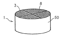
- FIG. 1( b ) is a diagram showing the embodiment of the honeycomb structure according to the present invention, and is a perspective view showing the honeycomb structure;
- FIG. 1( c ) is a diagram showing the embodiment of the honeycomb structure according to the present invention, and is a top plan view showing the honeycomb structure;
- FIG. 2( a ) is an explanatory view schematically showing one embodiment of a method for manufacturing the honeycomb structure according to the present invention
- FIG. 2( b ) is an explanatory view schematically showing the embodiment of the method for manufacturing the honeycomb structure according to the present invention.
- FIG. 2( c ) is an explanatory view schematically showing the embodiment of the method for manufacturing the honeycomb structure according to the present invention.
- FIG. 1 shows one embodiment of a honeycomb structure according to the present invention.
- FIG. 1( a ) is a perspective view showing a honeycomb segment.
- FIG. 1( b ) is a perspective view showing the honeycomb structure.
- FIG. 1( c ) is a top plan view showing the honeycomb structure.
- a honeycomb structure 1 according to the present embodiment a plurality of honeycomb segments 12 having cell structures 5 and porous outer walls 7 on outer peripheries of the cell structures 5 are integrated by bonding these outer walls 7 to one another with a bonding material 8 , each of the cell structures being provided with a plurality of cells 3 constituting fluid channels divided by porous partition walls 2 .
- a thermal conductivity is a coefficient indicating ease of occurrence of heat movement caused by a temperature difference in a substance.
- the thermal conductivity is indicated in a quantity of heat which moves as much as a unit area in a unit time, when there is a temperature difference of 1° C. per unit length (thickness). That is, when a temperature difference between a surface A (TA) and a surface B (TB) in a cube having a volume of 1 m 3 , the quantity of the heat which moves (A ⁇ B) as much as 1 m in one second is the thermal conductivity.
- the unit of the thermal conductivity is usually W/K. As the value of the thermal conductivity is large, the quantity of the heat which moves increases, and the heat is easily conducted.
- the thermal conductivity of a base material is the thermal conductivity of the honeycomb segment of the honeycomb structure, and is measured by, for example, a laser flash process.
- Cp specific heat
- ⁇ thermal diffusion
- a disc-like sample having a diameter of 8 to 10 mm and a thickness of 0.5 to 3 mm is irradiated with the laser light, and a temperature history curve in the back surface is analyzed to obtain the thermal conductivity.
- the laser flash process is suitable for measurement of a substance such as a metal or a ceramic having a satisfactory thermal conductivity.
- Other examples of the method for measuring the thermal conductivity include a heat line process, a flat plate heat flow meter process, and a temperature gradient process.
- the thermal conductivity of the base material according to the present invention is preferably 0.1 to 20 W/mK, further preferably 0.1 to 15 W/mK, especially preferably 0.1 to 10 W/mK.
- the honeycomb segment having the base material thermal conductivity in such a range is used, whereby an effect that a soot regeneration efficiency improves is produced.
- An outer periphery coating material is a bonding material which coats the outer periphery of the honeycomb segment in a step of bonding the honeycomb segments to one another to manufacture the honeycomb structure.
- the bonding material includes ceramic powder, an inorganic binder, a ceramic fiber and an organic binder.
- the ceramic powder for use in the present invention include a ceramic selected from the group consisting of silicon carbide (SiC), silicon nitride (SiNx), cordierite, silica, alumina, mullite, zirconia, zirconium phosphate, aluminum titanate, titania and a combination of them, an Fe—Cr—Al-based metal, a nickel-based metal, and a metal silicon (Si)-silicon carbide (SiC) composite material.
- silicon, silica, alumina, zirconia, aluminum titanate, mullite and cordierite are especially preferable.
- Examples of the inorganic binder for use in the present invention include silica sol, alumina sol, colloidal silica and colloidal alumina. These materials may be used alone or as a combination of two or more types of them.
- Ceramic fiber for use in the present invention examples include oxide fibers of mullite, aluminosilicate, alumina, magnesium silicate and magnesium calcium silicate.
- the outer periphery coating material of the present invention preferably contains oxide particles, an oxide fiber, a colloidal oxide, plate-like particles, an organic binder, or an organic or inorganic hollow balloon-like filler.
- the outer periphery coating material has a porosity of preferably 10 to 60%, further preferably 20 to 55%.
- the outer periphery coating material having the porosity in such a range is used, thereby producing an effect that the generation of crack in the honeycomb structure is suppressed and that the soot regeneration efficiency is improved.
- the outer periphery coating material preferably has a thermal conductivity of 0.01 to 0.5 W/mK.
- the outer periphery coating material in such a range is used, thereby producing the effect that the generation of the crack in the honeycomb structure is suppressed and that the soot regeneration efficiency is improved.
- the oxide particles have a particle diameter of preferably 0.1 to 30 ⁇ m, further preferably 1 to 30 ⁇ m and especially preferably 1 to 27 ⁇ m.
- the coating material containing the oxide particles having the particle diameter in this range is used, thereby producing the effect that the generation of the crack in the honeycomb structure is suppressed and that the soot regeneration efficiency is improved.
- the particle diameter of the oxide particles is the average particle diameter of the oxide particles.
- the average particle diameter is the peak value of a particle size distribution curve measured by a particle size distribution measurement device.
- Examples of a method for measuring the average particle diameter of the oxide particles include a light scattering process based on a difference of Brownian motion caused by a difference of particle size, a laser diffraction scattering process for measuring the particle size distribution by use of semiconductor laser, scattering principle and Fraunhofer diffraction principle, a powder specific surface area measurement process, a gravity sedimentation process and a central separation process.
- the outer periphery coating material preferably has a thickness of 0.01 to 1 mm.
- the outer periphery coating material having such a thickness is used, thereby producing the effect that the generation of the crack in the honeycomb structure is suppressed and that the soot regeneration efficiency is improved.
- Examples of the organic and/or inorganic hollow balloon-like filler are as follows.
- Examples of the organic hollow balloon-like filler include acrylic hollow particles, foam particles, a foam resin and a sponge-like foam body.
- Examples of the inorganic hollow balloon-like filler include hollow metal oxide fine particles such as hollow titanium oxide particles and hollow iron oxide particles.
- the honeycomb structure of the present invention is manufactured by bonding, with a bonding material, the honeycomb segments having a base material thermal conductivity of 0.1 to 20 W/mK.
- raw materials for manufacturing the honeycomb segments include a ceramic selected from the group consisting of silicon carbide (SiC), silicon nitride (SiNx), cordierite, silica, alumina, mullite, zirconia, zirconium phosphate, aluminum titanate, titania and a combination of them, an Fe—Cr—Al-based metal, a nickel-based metal, and a metal silicon (Si)-silicon carbide (SiC) composite material.
- silicon carbide, silicon nitride, the metal silicon-silicon carbide composite material, aluminum titanate or cordierite is especially preferable.
- a binder such as methyl cellulose or hydroxypropoxyl methyl cellulose, a surfactant, water and the like are added to the raw material, and this material is kneaded to form a plastic clay. Subsequently, the resultant clay is extruded and formed in a forming step, to form a formed honeycomb body having a plurality of cells constituting fluid channels divided by partition walls.
- a plunger type extruder, a biaxial screw type continuous extruder or the like may be used.
- a clay-forming step and a forming step can continuously be performed.
- the resultant formed honeycomb body can be dried by, for example, microwaves, dielectric heating and/or hot air, and then fired to obtain a fired honeycomb body.
- the resultant fired honeycomb body is processed into a honeycomb segment having a predetermined shape.
- the body is processed by use of means such as a band saw or a metal saw, whereby the square-pole-like honeycomb segment having a bonding surface can be obtained.
- honeycomb segments can be bonded to one another with a bonding material to obtain a honeycomb structure.
- a spray process, a coating process using a brush, a stylus or the like, a dipping process or the like may be employed.
- the coating material and the bonding material as mentioned in the present invention is to evaporate and solidify liquid components at such a temperature that components contained in the coating material and bonding material do not melt, that is, the components are substantially not fired. That is, in the honeycomb structure of the present embodiment, the coating material and bonding material are not fired, and are only dried, whereby bonding layers are formed to bond the outer walls of the honeycomb segments to one another. This does not easily cause bonding defects that the bonding layers are cracked or the bonding layers themselves peel owing to a difference of thermal expansion ratio or contraction ratio between the bonding layers and the honeycomb segments.
- the coating material and bonding material are not fired, and are only dried, whereby the bonding layers are formed to bond the outer walls of the honeycomb segments to one another. Therefore, in particular, when the honeycomb structure has a large size, an effect that the bonding defects are not easily generated is remarkably exerted.
- the outer periphery of the honeycomb structure (a bonded body) formed by bonding the honeycomb segments to one another may be removed, if necessary.
- preferably two or more cells 3 further preferably two to four cells 3 are removed from the outermost periphery.
- to remove the cells is to remove at least a part of the partition walls forming the cells to obtain a state in which four peripheries are completely not surrounded with the partition walls.
- the outer periphery of a bonded body 36 can be ground using grinding means such as a diamond tool 42 to remove a removal portion 41 including a plurality of cells 3 .
- the coating material 43 preferably contains at least one selected from the group consisting of colloidal silica, colloidal alumina, a ceramic fiber, ceramic particles, an organic binder, an inorganic binder and hollow particles.
- the ceramic particles include the particles of silica, alumina and zirconia.
- an outer periphery coater 48 shown in FIG. 2( b ) is used, whereby the outer peripheral wall having a uniform wall thickness can be formed.
- both end faces of the bonded body 36 having a part of the outer periphery removed are masked with pressing jigs 47 made of nylon, vinyl chloride or the like, and the bonded body 36 is held and fixed around a shaft 45 whose one end is provided with a rotating handle 46 . Subsequently, the handle 46 is rotated, and the outer periphery of the bonded body 36 can uniformly be coated with the coating material 43 by use of a smoothing plate 44 .
- the thickness of the formed outer peripheral wall can be set by appropriately adjusting the size of the pressing jigs 47 with respect to the size of the bonded body 36 .
- the coating material and bonding material of the present invention are not fired, and are only dried, whereby the bonding layers can be formed to bond bodies to be bonded to one another. Therefore, in particular, when the bodies to be bonded have a large size (an area to be coated with the bonding material is large), the effect that the bonding defects are not easily generated is remarkably exerted.
- SiC raw material powder and metal silicon powder were mixed at a mass ratio shown in Table 1, and starch and a foam resin as pore formers, further methyl cellulose, hydroxypropoxyl methyl cellulose, a surfactant and water were added to the material to prepare a plastic clay.
- This clay was extruded, formed, and dried by microwaves and hot air to obtain a honeycomb segment including partition walls having a thickness of 310 ⁇ m, having a cell density of about 46.5 cells/cm 2 (300 cells/square inch), having a square section with each 35 mm long side and having a length of 152 mm.
- honeycomb segment the ends of the adjacent cells on opposite sides were plugged by use of a material similar to that used in manufacturing a honeycomb segment 2 so that the end faces of the segment have a checkered pattern. Afterward, the segment was dried, then degreased in the atmosphere at about 400° C. and then fired in an Ar inactive atmosphere at about 1450° C. to obtain Si—SiC honeycomb segments. The thermal conductivities of the respective honeycomb segments were measured by a laser flash process, and the results are shown in Table 1.
- coating materials A to F of the present invention 35 mass % of oxide particles of alumina, silica or zirconia, 22 mass % of an aluminosilicate fiber as an oxide fiber, 40 mass % of silica sol as an inorganic binder, 19.5 mass % of an aqueous solution, 1 mass % of clay and 0.1 mass % of methyl cellulose as an organic binder were mixed. Afterward, water was added to the mixture, and the mixture was kneaded using a mixer for 30 minutes to obtain the coating materials.
- the compositions of the coating materials are shown in Table 2. Moreover, Table 2 similarly shows the compositions of coating materials G to J as comparative examples.
- the outer periphery of a bonded body obtained by bonding 16 fired honeycomb segments shown in Table 1 was ground, and the corresponding outer peripheral portion was individually coated with each of the coating materials A to F of the present invention and the coating materials G to J of the comparative examples shown in Table 2. Afterward, the bonded body was dried at 200° C. for two hours to obtain a honeycomb structure.
- honeycomb structures having combinations shown in Tables 3, 4 and 5 were attached to the exhaust tube of a diesel engine, and 5 g/L of soot was accumulated in each honeycomb structure. Afterward, soot regeneration was performed at an exhaust gas flow rate of 2 m 3 /min. Each regenerated honeycomb structure was subjected to a thermal treatment in an electric furnace at 700° C. for ten hours, and a difference between a weight before the treatment and a weight after the treatment was obtained as a residual amount of soot.
- oxide particles having a low thermal conductivity are used, whereby the thermal conductivity of the coating material can be decreased, and the residual amount of soot can be prevented from being increased.
- the particles of silicon carbide having a high thermal conductivity are used as in Comparative Examples 5 and 6, it is difficult to set the thermal conductivity of the coating material to a range of 0.01 to 0.5 W/mK or to inhibit the crack generation. Moreover, the soot regeneration efficiency lowers, and crack is generated.
- the porosity is increased, whereby the thermal conductivity of the coating material is effectively decreased.
- the porosity of the coating material is in a range of 10 to 60%, especially 20 to 55%, any crack is not generated.
- the porosity is 65%, the strength lowers, and the crack is generated.
- the thermal conductivity of the coating material is decreased, and an insulation effect is improved, whereby the increase of the efficiency during the soot regeneration is achieved.
- the porosity of the coating material is defined to provide the coating material having a low thermal conductivity and a high strength, and both the inhibition of the crack generation and the increase of the soot regeneration efficiency are achieved.
- a honeycomb structure according to the present invention is useful as a trap filter for an exhaust gas, for example, a diesel particulate filter (DPF) for trapping and removing a particulate matter (particulates) included in an exhaust gas from a diesel engine or the like.
- DPF diesel particulate filter
Abstract
Description
| TABLE 1 | |||
| Amount of SiC | Amount of metal Si | ||
| powder to be | powder to be | Thermal | |
| Base | blended | blended | conductivity |
| material No. | % | % | W(mK)−1 |
| 1 | 80 | 20 | 19 |
| 2 | 90 | 10 | 15 |
| 3 | 93 | 7 | 9 |
| 4 | 97 | 3 | 3 |
| 5 | 65 | 35 | 25 |
| TABLE 2 | ||||
| Oxide particle | ||||
| average | ||||
| Coating | particle | Foam | Thermal | |
| material | Oxide | diameter | resin | conductivity |
| No. | particles | μm | % | W(mK)−1 |
| A | |
1 | 3 | 0.2 | |
| | Alumina | 1 | 3 | 0.2 | |
| | Zirconia | 1 | 3 | 0.2 | |
| | Silica | 1 | 0 | 0.4 | |
| | Silica | 1 | 5 | 0.1 | |
| F | Silica | 25 | 3 | 0.3 | |
| G | Silica | 35 | 3 | 0.6 | |
| | Silica | 1 | 8 | 0.03 | |
| | Silicon | 1 | 3 | 0.8 | |
| | |||||
| J | Silicon | ||||
| 1 | 8 | 0.4 | |||
| carbide | |||||
| TABLE 3 | ||||||
| Residual | ||||||
| Base | Coating | Thermal conductivity | Thermal conductivity | amount | ||
| material | material | of base material | of coating material | of soot | ||
| No. | No. | W(mK)−1 | W(mK)−1 | gL−1 | ||
| Example 1 | 4 | A | 3 | 0.2 | 0.1 |
| Example 2 | 1 | A | 19 | 0.2 | 0 |
| Example 3 | 5 | A | 25 | 0.2 | 0 |
| Example 4 | 3 | D | 9 | 0.4 | 0.2 |
| Comparative | 4 | I | 3 | 0.8 | 2 |
| Example 1 | |||||
| Comparative | 1 | I | 19 | 0.8 | 0.6 |
| Example 2 | |||||
| Comparative | 5 | I | 25 | 0.8 | 0.1 |
| Example 3 | |||||
| Comparative | 3 | G | 9 | 0.6 | 0.7 |
| Example 4 | |||||
| TABLE 4 | ||||||||
| Thermal | ||||||||
| conductivity | Residual | Coating | ||||||
| Base | Coating | of coating | amount of | Presence | material | |||
| material | material | material | soot | Porosity | of | strength | ||
| No. | No. | W(mK)−1 | gL−1 | % | crack | MPa | ||
| Example 5 | 3 | A | 0.2 | 0 | 41 | No crack | 2.1 |
| Example 6 | 3 | B | 0.2 | 0 | 43 | No crack | 2.2 |
| Example 7 | 3 | C | 0.2 | 0 | 42 | No crack | 2.1 |
| Comparative | 3 | I | 0.8 | 1.6 | 42 | No crack | 2.3 |
| Example 5 | |||||||
| Comparative | 3 | J | 0.4 | 0.1 | 66 | Cracked | 0.3 |
| Example 6 | |||||||
| TABLE 5 | |||||||
| Oxide | |||||||
| particles | Thermal | Thermal | |||||
| average | conductivity | conductivity | Residual | ||||
| Base | Coating | particle | of base | of coating | amount | ||
| material | material | diameter | material | material | of soot | ||
| No. | No. | μm | W(mK)−1 | W(mK)−1 | gL−1 | ||
| Example 8 | 2 | A | 1 | 19 | 0.2 | 0 |
| Example 9 | 2 | F | 25 | 19 | 0.3 | 0 |
| Comparative | 2 | G | 35 | 19 | 0.6 | 0.4 |
| Example 7 | ||||||
| TABLE 6 | |||||||||
| Oxide | |||||||||
| particles | Thermal | ||||||||
| average | conductivity | Coating | |||||||
| Coating | particle | Foam | of coating | material | Presence | ||||
| material | Oxide | diameter | resin | Porosity | material | strength | of | ||
| No. | particles | μm | % | % | W(mK)−1 | MPa | crack | ||
| Example 10 | A | |
1 | 3 | 41 | 0.2 | 2.1 | No crack | |
| Example 11 | | Alumina | 1 | 3 | 43 | 0.2 | 2.2 | No crack | |
| Example 12 | | Zirconia | 1 | 3 | 42 | 0.2 | 2.1 | No crack | |
| Example 13 | | Silica | 1 | 0 | 20 | 0.3 | 5.3 | No crack | |
| Example 14 | | Silica | 1 | 6 | 55 | 0.1 | 1.2 | No crack | |
| | H | Silica | 1 | 10 | 65 | 0.03 | 0.2 | Cracked | |
| Example 8 | |||||||||
Claims (7)
Applications Claiming Priority (3)
| Application Number | Priority Date | Filing Date | Title |
|---|---|---|---|
| JP2006-094267 | 2006-03-30 | ||
| JP2006094267 | 2006-03-30 | ||
| PCT/JP2007/052787 WO2007125667A1 (en) | 2006-03-30 | 2007-02-15 | Honeycomb structure body |
Related Parent Applications (1)
| Application Number | Title | Priority Date | Filing Date |
|---|---|---|---|
| PCT/JP2007/052787 Continuation WO2007125667A1 (en) | 2006-03-30 | 2007-02-15 | Honeycomb structure body |
Publications (2)
| Publication Number | Publication Date |
|---|---|
| US20090022944A1 US20090022944A1 (en) | 2009-01-22 |
| US7670664B2 true US7670664B2 (en) | 2010-03-02 |
Family
ID=38655207
Family Applications (1)
| Application Number | Title | Priority Date | Filing Date |
|---|---|---|---|
| US12/239,260 Active US7670664B2 (en) | 2006-03-30 | 2008-09-26 | Honeycomb structure body |
Country Status (5)
| Country | Link |
|---|---|
| US (1) | US7670664B2 (en) |
| EP (1) | EP2008987B1 (en) |
| JP (1) | JP5469337B2 (en) |
| KR (1) | KR20090017484A (en) |
| WO (1) | WO2007125667A1 (en) |
Cited By (1)
| Publication number | Priority date | Publication date | Assignee | Title |
|---|---|---|---|---|
| US20110094419A1 (en) * | 2008-12-15 | 2011-04-28 | Fernando Joseph A | Ceramic Honeycomb Structure Skin Coating |
Families Citing this family (8)
| Publication number | Priority date | Publication date | Assignee | Title |
|---|---|---|---|---|
| JP2011504159A (en) * | 2007-11-05 | 2011-02-03 | コーニング インコーポレイテッド | Low expansion cement composition for ceramic monoliths |
| KR101251104B1 (en) * | 2007-11-08 | 2013-04-04 | (주)엘지하우시스 | Composition for particulate filter, SiC DPF and method for manufacturing the same |
| US9139479B2 (en) * | 2012-02-24 | 2015-09-22 | Corning Incorporated | Honeycomb structure comprising a cement skin composition with crystalline inorganic fibrous material |
| WO2013145319A1 (en) * | 2012-03-30 | 2013-10-03 | イビデン株式会社 | Honeycomb filter |
| NL2009962C2 (en) | 2012-12-11 | 2014-06-12 | Draka Comteq Bv | Method for activating an inner surface of a hollow glass substrate tube for the manufacturing of an optical fiber preform. |
| JP6398546B2 (en) * | 2014-09-30 | 2018-10-03 | 日立金属株式会社 | Ceramic honeycomb structure, manufacturing method thereof, and coating material |
| JP6953348B2 (en) * | 2018-03-30 | 2021-10-27 | 日本碍子株式会社 | Coating Material, Outer Coat Silicon Carbide Honeycomb Structure, and Method of Coating the Outer Periphery of Silicon Carbide Honeycomb Structure |
| JP7329950B2 (en) * | 2019-03-29 | 2023-08-21 | 日本碍子株式会社 | Particulate filter and canning structure |
Citations (5)
| Publication number | Priority date | Publication date | Assignee | Title |
|---|---|---|---|---|
| JP2000007455A (en) | 1998-06-25 | 2000-01-11 | Ibiden Co Ltd | Ceramic structure joining apparatus and method therefor |
| JP2001162119A (en) | 1999-09-29 | 2001-06-19 | Ibiden Co Ltd | Ceramic filter aggregate |
| JP2002273137A (en) | 2001-03-22 | 2002-09-24 | Ibiden Co Ltd | Ceramic filter assembly |
| US6669751B1 (en) | 1999-09-29 | 2003-12-30 | Ibiden Co., Ltd. | Honeycomb filter and ceramic filter assembly |
| WO2005089901A1 (en) | 2004-03-23 | 2005-09-29 | Ngk Insulators, Ltd. | Honeycomb structure and method for manufacturing the same |
Family Cites Families (5)
| Publication number | Priority date | Publication date | Assignee | Title |
|---|---|---|---|---|
| JP2613729B2 (en) * | 1992-01-30 | 1997-05-28 | 日本碍子株式会社 | Ceramic honeycomb structure, method of manufacturing the same, and coating material therefor |
| JP4657566B2 (en) * | 2002-07-16 | 2011-03-23 | 日本碍子株式会社 | Honeycomb structure and manufacturing method thereof |
| JP4550434B2 (en) * | 2004-01-15 | 2010-09-22 | 日本碍子株式会社 | Cell structure and manufacturing method thereof |
| JP2005324092A (en) * | 2004-05-12 | 2005-11-24 | Ibiden Co Ltd | Filter, exhaust gas purifying device of internal combustion engine and exhaust gas purifying method |
| JPWO2006001509A1 (en) * | 2004-06-25 | 2008-04-17 | イビデン株式会社 | Porous body manufacturing method, porous body and honeycomb structure |
-
2007
- 2007-02-15 JP JP2008513093A patent/JP5469337B2/en active Active
- 2007-02-15 KR KR1020087025920A patent/KR20090017484A/en not_active Application Discontinuation
- 2007-02-15 EP EP07714317.0A patent/EP2008987B1/en active Active
- 2007-02-15 WO PCT/JP2007/052787 patent/WO2007125667A1/en active Application Filing
-
2008
- 2008-09-26 US US12/239,260 patent/US7670664B2/en active Active
Patent Citations (8)
| Publication number | Priority date | Publication date | Assignee | Title |
|---|---|---|---|---|
| JP2000007455A (en) | 1998-06-25 | 2000-01-11 | Ibiden Co Ltd | Ceramic structure joining apparatus and method therefor |
| JP2001162119A (en) | 1999-09-29 | 2001-06-19 | Ibiden Co Ltd | Ceramic filter aggregate |
| US6669751B1 (en) | 1999-09-29 | 2003-12-30 | Ibiden Co., Ltd. | Honeycomb filter and ceramic filter assembly |
| US20040055265A1 (en) | 1999-09-29 | 2004-03-25 | Ibiden Co., Ltd., | Honeycomb filter and ceramic filter assembly |
| US20060021310A1 (en) | 1999-09-29 | 2006-02-02 | Ibiden Co., Ltd. | Honeycomb filter and ceramic filter assembly |
| JP2002273137A (en) | 2001-03-22 | 2002-09-24 | Ibiden Co Ltd | Ceramic filter assembly |
| WO2005089901A1 (en) | 2004-03-23 | 2005-09-29 | Ngk Insulators, Ltd. | Honeycomb structure and method for manufacturing the same |
| US20070082174A1 (en) | 2004-03-23 | 2007-04-12 | Ngk Insulators, Ltd. | Honeycomb structure and method for manufacturing the same |
Cited By (6)
| Publication number | Priority date | Publication date | Assignee | Title |
|---|---|---|---|---|
| US20110094419A1 (en) * | 2008-12-15 | 2011-04-28 | Fernando Joseph A | Ceramic Honeycomb Structure Skin Coating |
| US8263512B2 (en) * | 2008-12-15 | 2012-09-11 | Unifrax I Llc | Ceramic honeycomb structure skin coating |
| US8679615B2 (en) * | 2008-12-15 | 2014-03-25 | Unifrax I Llc | Ceramic honeycomb structure skin coating |
| US8696807B2 (en) * | 2008-12-15 | 2014-04-15 | Unifrax I Llc | Ceramic honeycomb structure skin coating |
| US20140165876A1 (en) * | 2008-12-15 | 2014-06-19 | Unifrax I Llc | Ceramic Honeycomb Structure Skin Coating |
| US9163148B2 (en) * | 2008-12-15 | 2015-10-20 | Unifrax I Llc | Ceramic honeycomb structure skin coating |
Also Published As
| Publication number | Publication date |
|---|---|
| EP2008987A1 (en) | 2008-12-31 |
| JPWO2007125667A1 (en) | 2009-09-10 |
| KR20090017484A (en) | 2009-02-18 |
| WO2007125667A1 (en) | 2007-11-08 |
| EP2008987A4 (en) | 2012-06-06 |
| US20090022944A1 (en) | 2009-01-22 |
| EP2008987B1 (en) | 2018-06-27 |
| JP5469337B2 (en) | 2014-04-16 |
Similar Documents
| Publication | Publication Date | Title |
|---|---|---|
| US7670664B2 (en) | Honeycomb structure body | |
| US8105675B2 (en) | Honeycomb structure and bonding material to be used for same | |
| JP4331575B2 (en) | Honeycomb structure, manufacturing method thereof, and bonding material | |
| JP5485546B2 (en) | Bonded body, honeycomb segment bonded body, and honeycomb structure using the same | |
| JP5315997B2 (en) | Ceramic honeycomb structure and method for manufacturing ceramic honeycomb structure | |
| KR100833140B1 (en) | Honeycomb structure | |
| US7396576B2 (en) | Honeycomb structure | |
| US20070068128A1 (en) | Honeycomb structure and manufacturing method for honeycomb structure | |
| JP5805039B2 (en) | Honeycomb structure | |
| WO2007037222A1 (en) | Honeycomb filter | |
| JP2003275521A (en) | Honeycomb filter | |
| WO2005099865A1 (en) | Honeycomb structure, method of manufacturing honeycomb structure, and exhaust emission control device | |
| US8053054B2 (en) | Honeycomb structure | |
| EP2123617A1 (en) | Joining material composition, method for production of the joining material composition, jointed article, and method for production of the jointed article | |
| JP6847724B2 (en) | Sealed honeycomb structure | |
| US20100093528A1 (en) | Honeycomb structure | |
| JP2001096116A (en) | Ceramic filter aggregate and honeycomb filter | |
| WO2004096414A1 (en) | Honeycomb structure body | |
| JP6068274B2 (en) | Honeycomb structure | |
| EP1600433A1 (en) | Honeycomb structure | |
| JP2008100408A (en) | Ceramic honeycomb structure | |
| JP5604047B2 (en) | Honeycomb structure | |
| JP6948273B2 (en) | Honeycomb filter | |
| JP6059181B2 (en) | Honeycomb structure | |
| KR100595768B1 (en) | Honeycomb structure body and method for manufacturing the same |
Legal Events
| Date | Code | Title | Description |
|---|---|---|---|
| AS | Assignment |
Owner name: NGK INSULATORS, LTD., JAPAN Free format text: ASSIGNMENT OF ASSIGNORS INTEREST;ASSIGNORS:WATANABE, ATSUSHI;MASUKAWA, NAOSHI;ICHIKAWA, SHUICHI;REEL/FRAME:021605/0445 Effective date: 20080730 Owner name: NGK INSULATORS, LTD.,JAPAN Free format text: ASSIGNMENT OF ASSIGNORS INTEREST;ASSIGNORS:WATANABE, ATSUSHI;MASUKAWA, NAOSHI;ICHIKAWA, SHUICHI;REEL/FRAME:021605/0445 Effective date: 20080730 |
|
| STCF | Information on status: patent grant |
Free format text: PATENTED CASE |
|
| FEPP | Fee payment procedure |
Free format text: PAYOR NUMBER ASSIGNED (ORIGINAL EVENT CODE: ASPN); ENTITY STATUS OF PATENT OWNER: LARGE ENTITY |
|
| FPAY | Fee payment |
Year of fee payment: 4 |
|
| FPAY | Fee payment |
Year of fee payment: 8 |
|
| MAFP | Maintenance fee payment |
Free format text: PAYMENT OF MAINTENANCE FEE, 12TH YEAR, LARGE ENTITY (ORIGINAL EVENT CODE: M1553); ENTITY STATUS OF PATENT OWNER: LARGE ENTITY Year of fee payment: 12 |