US7671845B2 - Directional input device and display orientation control - Google Patents
Directional input device and display orientation control Download PDFInfo
- Publication number
- US7671845B2 US7671845B2 US10/999,082 US99908204A US7671845B2 US 7671845 B2 US7671845 B2 US 7671845B2 US 99908204 A US99908204 A US 99908204A US 7671845 B2 US7671845 B2 US 7671845B2
- Authority
- US
- United States
- Prior art keywords
- orientation
- image
- input device
- directional input
- display
- Prior art date
- Legal status (The legal status is an assumption and is not a legal conclusion. Google has not performed a legal analysis and makes no representation as to the accuracy of the status listed.)
- Active, expires
Links
Images


Classifications
-
- G—PHYSICS
- G06—COMPUTING; CALCULATING OR COUNTING
- G06F—ELECTRIC DIGITAL DATA PROCESSING
- G06F1/00—Details not covered by groups G06F3/00 - G06F13/00 and G06F21/00
- G06F1/16—Constructional details or arrangements
- G06F1/1613—Constructional details or arrangements for portable computers
- G06F1/1633—Constructional details or arrangements of portable computers not specific to the type of enclosures covered by groups G06F1/1615 - G06F1/1626
- G06F1/1684—Constructional details or arrangements related to integrated I/O peripherals not covered by groups G06F1/1635 - G06F1/1675
- G06F1/169—Constructional details or arrangements related to integrated I/O peripherals not covered by groups G06F1/1635 - G06F1/1675 the I/O peripheral being an integrated pointing device, e.g. trackball in the palm rest area, mini-joystick integrated between keyboard keys, touch pads or touch stripes
-
- G—PHYSICS
- G06—COMPUTING; CALCULATING OR COUNTING
- G06F—ELECTRIC DIGITAL DATA PROCESSING
- G06F3/00—Input arrangements for transferring data to be processed into a form capable of being handled by the computer; Output arrangements for transferring data from processing unit to output unit, e.g. interface arrangements
-
- G—PHYSICS
- G06—COMPUTING; CALCULATING OR COUNTING
- G06F—ELECTRIC DIGITAL DATA PROCESSING
- G06F1/00—Details not covered by groups G06F3/00 - G06F13/00 and G06F21/00
- G06F1/16—Constructional details or arrangements
- G06F1/1613—Constructional details or arrangements for portable computers
- G06F1/1626—Constructional details or arrangements for portable computers with a single-body enclosure integrating a flat display, e.g. Personal Digital Assistants [PDAs]
-
- G—PHYSICS
- G06—COMPUTING; CALCULATING OR COUNTING
- G06F—ELECTRIC DIGITAL DATA PROCESSING
- G06F3/00—Input arrangements for transferring data to be processed into a form capable of being handled by the computer; Output arrangements for transferring data from processing unit to output unit, e.g. interface arrangements
- G06F3/01—Input arrangements or combined input and output arrangements for interaction between user and computer
- G06F3/03—Arrangements for converting the position or the displacement of a member into a coded form
- G06F3/033—Pointing devices displaced or positioned by the user, e.g. mice, trackballs, pens or joysticks; Accessories therefor
- G06F3/0338—Pointing devices displaced or positioned by the user, e.g. mice, trackballs, pens or joysticks; Accessories therefor with detection of limited linear or angular displacement of an operating part of the device from a neutral position, e.g. isotonic or isometric joysticks
-
- G—PHYSICS
- G06—COMPUTING; CALCULATING OR COUNTING
- G06F—ELECTRIC DIGITAL DATA PROCESSING
- G06F3/00—Input arrangements for transferring data to be processed into a form capable of being handled by the computer; Output arrangements for transferring data from processing unit to output unit, e.g. interface arrangements
- G06F3/01—Input arrangements or combined input and output arrangements for interaction between user and computer
- G06F3/03—Arrangements for converting the position or the displacement of a member into a coded form
- G06F3/033—Pointing devices displaced or positioned by the user, e.g. mice, trackballs, pens or joysticks; Accessories therefor
- G06F3/0354—Pointing devices displaced or positioned by the user, e.g. mice, trackballs, pens or joysticks; Accessories therefor with detection of 2D relative movements between the device, or an operating part thereof, and a plane or surface, e.g. 2D mice, trackballs, pens or pucks
- G06F3/03547—Touch pads, in which fingers can move on a surface
-
- G—PHYSICS
- G06—COMPUTING; CALCULATING OR COUNTING
- G06F—ELECTRIC DIGITAL DATA PROCESSING
- G06F3/00—Input arrangements for transferring data to be processed into a form capable of being handled by the computer; Output arrangements for transferring data from processing unit to output unit, e.g. interface arrangements
- G06F3/01—Input arrangements or combined input and output arrangements for interaction between user and computer
- G06F3/03—Arrangements for converting the position or the displacement of a member into a coded form
- G06F3/033—Pointing devices displaced or positioned by the user, e.g. mice, trackballs, pens or joysticks; Accessories therefor
- G06F3/0362—Pointing devices displaced or positioned by the user, e.g. mice, trackballs, pens or joysticks; Accessories therefor with detection of 1D translations or rotations of an operating part of the device, e.g. scroll wheels, sliders, knobs, rollers or belts
-
- G—PHYSICS
- G06—COMPUTING; CALCULATING OR COUNTING
- G06F—ELECTRIC DIGITAL DATA PROCESSING
- G06F3/00—Input arrangements for transferring data to be processed into a form capable of being handled by the computer; Output arrangements for transferring data from processing unit to output unit, e.g. interface arrangements
- G06F3/01—Input arrangements or combined input and output arrangements for interaction between user and computer
- G06F3/048—Interaction techniques based on graphical user interfaces [GUI]
- G06F3/0484—Interaction techniques based on graphical user interfaces [GUI] for the control of specific functions or operations, e.g. selecting or manipulating an object, an image or a displayed text element, setting a parameter value or selecting a range
- G06F3/0485—Scrolling or panning
-
- G—PHYSICS
- G06—COMPUTING; CALCULATING OR COUNTING
- G06F—ELECTRIC DIGITAL DATA PROCESSING
- G06F3/00—Input arrangements for transferring data to be processed into a form capable of being handled by the computer; Output arrangements for transferring data from processing unit to output unit, e.g. interface arrangements
- G06F3/14—Digital output to display device ; Cooperation and interconnection of the display device with other functional units
-
- G—PHYSICS
- G06—COMPUTING; CALCULATING OR COUNTING
- G06F—ELECTRIC DIGITAL DATA PROCESSING
- G06F2200/00—Indexing scheme relating to G06F1/04 - G06F1/32
- G06F2200/16—Indexing scheme relating to G06F1/16 - G06F1/18
- G06F2200/161—Indexing scheme relating to constructional details of the monitor
- G06F2200/1614—Image rotation following screen orientation, e.g. switching from landscape to portrait mode
Definitions
- aspects of the present invention relate to computer processing and information manipulation. More specifically, aspects of the present invention relate to a directional input device that is associated with orientation of a corresponding display, and to changing the image orientation of a display screen.
- the invention has application to computing devices having displays with a plurality of orientation modes and to a directional input device, such as a mouse wheel or a touch pad.
- Typical computer systems especially computer systems using graphical user interface (GUI) systems such as Microsoft WINDOWS, are optimized for accepting user input from one or more discrete input devices, such as a keyboard for entering text and a pointing device such as a mouse with one or more buttons for driving the user interface.
- GUI graphical user interface
- the ubiquitous keyboard and mouse interface provides for fast creation and modification of documents, spreadsheets, database fields, drawings, photos and the like.
- Some computer systems permit a user to write on a screen using, for example, a stylus.
- the Microsoft READER application permits one to add electronic ink to a document much the same way that a user would write with a standard pen and paper.
- Most hand-held computing devices commonly known as Personal Digital Assistants (PDAs), also permit the user to write on the screen.
- PDAs Personal Digital Assistants
- Many of these computing devices are designed to support switching the electronic display between two orientation modes rotated ninety degrees from each other, such as a portrait mode and a landscape mode.
- auxiliary input devices such as a keyboard or a mouse.
- auxiliary input devices may include directional input devices, such as a scroll wheel, which can be useful for scrolling a displayed image in linear direction.
- a directional input device has limited ability to work in both display orientations. They are typically arranged for a default display orientation, such as the portrait mode, and do not work well in the alternate display mode.
- aspects of the present invention address one or more of the issues mentioned above, thereby providing a better integration of directional input devices and display orientation control for a computer system having multiple display orientations.
- Various aspects of the invention may include a directional input device that automatically causes the display orientation to change based on a change in the orientation of the directional input device.
- Additional aspects of the invention may include movable directional input devices that indicate the orientation state of a display.
- Other aspects may include indicators, physical features and sensors that can provide related functionality.
- Further aspects include methods for switching the orientation of an image on a display screen from a first orientation to a second orientation.
- computer-executable instructions for implementing the disclosed methods are stored on computer-readable media.
- FIG. 1 shows a general-purpose computer supporting one or more aspects of the present invention.
- FIG. 2A is a top plan view of a stylus-based computer having a first display orientation according to aspects of the present invention.
- FIG. 2B is a top plan view of the stylus-based computer of FIG. 2A having a second display orientation.
- FIG. 3A is a close-up view of a directional input device of the stylus-based computer of FIGS. 2A and 2B .
- FIG. 3B is a schematic perspective view of a scroll wheel assembly of the directional input device of FIG. 3A .
- FIG. 3C is a schematic elevational view of the directional input device of FIG. 3A .
- FIGS. 3D-3F are schematic top views of the directional input device of FIG. 3A illustrating movement of the directional input device from a first orientation to a second orientation in accordance with aspects of the present invention.
- FIG. 4 shows a process for switching the orientation of an image on a display screen from a first orientation to a second orientation in accordance with aspects of the present invention.
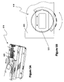
- FIG. 5A is a perspective view of a fingerprint scanner input device in accordance with aspects of the present invention, illustrating the platen assembly moved away from a default position.
- FIG. 5B is a top plan view of another embodiment of a directional input device that includes the fingerprint scanner input device of FIG. 5A .
- FIG. 6 is a top plan view of a further embodiment of a directional input device in accordance with aspects of the present invention.
- FIG. 7 is a top plan view of an additional embodiment of a directional input device in accordance with aspects of the present invention.
- aspects of the present invention relate to switching display orientations and to directional input devices associated therewith.
- Directional input device An input device for receiving user input to modify a display in a substantially linear direction using a graphical user interface (GUI) system, such as Microsoft WINDOWS.
- GUI graphical user interface
- the input device may receive user input to modify the display in a various linear directions. Modification of the display may include scanning displayed content shown on the display in a user-selected linear direction, such as by scrolling a document, moving a cursor on the display in the selected linear direction, and translating a selected item shown on the display in the selected linear direction.
- a directional input device may include a scroll wheel, a track ball, a sweep sensor and a touch pad.
- a document may include a web page, a word processing document, a note page or pad, a spreadsheet, a visual presentation, a database record, image files, and combinations thereof.
- Light-transmitting Partially or completely transparent; Allowing light to pass through freely or diffusely.
- Orientation indicator A device for showing the display orientation condition of a computing apparatus.
- Scan Move through display content in order to show parts of the content that do not fit on the display.
- System state A temporary condition, attribute, configuration or information content of a computing device.
- a system state may include a sleep configuration, an error condition, a low power condition, a display orientation condition, or human contact with a human-contact surface or a proximity sensor.
- FIG. 1 illustrates a schematic diagram of an illustrative conventional general-purpose digital computing environment that can be used to implement various aspects of the present invention.
- a computer 100 includes a processing unit 110 , a system memory 120 , and a system bus 130 that couples various system components including the system memory to the processing unit 110 .
- the system bus 130 may be any of several types of bus structures including a memory bus or memory controller, a peripheral bus, and a local bus using any of a variety of bus architectures.
- the system memory 120 includes read only memory (ROM) 140 and random access memory (RAM) 150 .
- a basic input/output system 160 (BIOS), containing the basic routines that help to transfer information between elements within the computer 100 , such as during start-up, is stored in the ROM 140 .
- the computer 100 also includes a hard disk drive 170 for reading from and writing to a hard disk (not shown), a magnetic disk drive 180 for reading from or writing to a removable magnetic disk 190 , and an optical disk drive 191 for reading from or writing to a removable optical disk 192 such as a CD ROM or other optical media.
- the hard disk drive 170 , magnetic disk drive 180 , and optical disk drive 191 are connected to the system bus 130 by a hard disk drive interface 192 , a magnetic disk drive interface 193 , and an optical disk drive interface 194 , respectively.
- the drives and their associated computer-readable media provide nonvolatile storage of computer readable instructions, data structures, program modules and other data for the personal computer 100 . It will be appreciated by those skilled in the art that other types of computer readable media that can store data that is accessible by a computer, such as magnetic cassettes, flash memory cards, digital video disks, Bernoulli cartridges, random access memories (RAMs), read only memories (ROMs), and the like, may also be used in the example operating environment.
- RAMs random access memories
- ROMs read only memories
- a number of program modules can be stored on the hard disk drive 170 , magnetic disk 190 , optical disk 192 , ROM 140 or RAM 150 , including an operating system 195 , one or more application programs 196 , other program modules 197 , and program data 198 .
- a user can enter commands and information into the computer 100 through input devices such as a keyboard 101 and pointing device or other input device 102 .
- Other input devices may include a directional input device, a microphone, a joystick, a game pad, a satellite dish, scanner or the like.
- serial port interface 106 that is coupled to the system bus, but may be connected by other interfaces, such as a parallel port, game port or a universal serial bus (USB). Further still, these devices may be coupled directly to the system bus 130 via an appropriate interface (not shown).
- a monitor 107 or other type of display device is also connected to the system bus 130 via an interface, such as a video adapter 108 .
- personal computers typically include other peripheral output devices (not shown), such as speakers and printers.
- a pen digitizer 165 and accompanying pen or stylus 166 are provided in order to digitally capture freehand input.
- the pen digitizer 165 may be coupled to the processing unit 110 directly, parallel port or other interface and the system bus 130 by any technique including wirelessly.
- the pen 166 may have a camera associated with it and a transceiver for wirelessly transmitting image information captured by the camera to an interface interacting with bus 130 .
- the pen may have other sensing systems in addition to or in place of the camera for determining strokes of electronic ink including accelerometers, magnetometers, and gyroscopes.
- the digitizer 165 is shown apart from the monitor 107 , the usable input area of the digitizer 165 may be co-extensive with the display area of the monitor 107 . Further still, the digitizer 165 may be integrated in the monitor 107 , or may exist as a separate device overlaying or otherwise appended to the monitor 107 .
- the computer 100 can operate in a networked environment using logical connections to one or more remote computers, such as a remote computer 109 .
- the remote computer 109 can be a server, a router, a network PC, a peer device or other common network node, and typically includes many or all of the elements described above relative to the computer 100 , although only a memory storage device 111 has been illustrated in FIG. 1 .
- the logical connections depicted in FIG. 1 include a local area network (LAN) 112 and a wide area network (WAN) 113 .
- LAN local area network
- WAN wide area network
- the computer 100 When used in a LAN networking environment, the computer 100 is connected to the local network 112 through a network interface or adapter 114 .
- the personal computer 100 When used in a WAN networking environment, the personal computer 100 typically includes a modem 115 or other means for establishing a communications over the wide area network 113 , such as the Internet.
- the modem 115 which may be internal or external, is connected to the system bus 130 via the serial port interface 106 .
- program modules depicted relative to the personal computer 100 may be stored in the remote memory storage device.
- the system may include wired and/or wireless capabilities.
- network interface 114 may include Bluetooth, SWLan, and/or IEEE 802.11 class of combination abilities. It is appreciated that other wireless communication protocols may be used in conjunction with these protocols or in place of these protocols.
- network connections shown are illustrative and other techniques for establishing a communications link between the computers can be used.
- the existence of any of various well-known protocols such as TCP/IP, Ethernet, FTP, HTTP and the like is presumed, and the system can be operated in a client-server configuration to permit a user to retrieve web pages from a web-based server.
- Any of various conventional web browsers can be used to display and manipulate data on web pages.
- FIG. 2A illustrates an illustrative tablet PC 201 that can be used in accordance with various aspects of the present invention. Any or all of the features, subsystems, and functions in the system of FIG. 1 can be included in the computer of FIG. 2A .
- Tablet PC 201 includes a housing 220 and a large display surface 202 , e.g., a digitizing flat panel display, preferably, a liquid crystal display (LCD) screen, on which a plurality of windows may be displayed.
- a single window is shown displaying a textual document 208 , a vertical scroll bar 210 , a horizontal scroll bar 212 , a header menu 214 , and a toolbar 216 .
- Textual document 208 is shown being displayed in a first orientation, such as portrait mode.
- a user can select, highlight, and/or write on the digitizing display surface 202 .
- suitable digitizing display surfaces 202 include electromagnetic pen digitizers, such as Mutoh or Wacom pen digitizers. Other types of pen digitizers, e.g., optical digitizers, may also be used.
- Tablet PC 201 interprets gestures made using stylus 204 in order to manipulate data, enter text, create drawings, and/or execute conventional computer application tasks such as spreadsheets, word processing programs, and the like.
- the stylus 204 may be equipped with one or more buttons or other features to augment its selection capabilities.
- the stylus 204 could be implemented as a “pencil” or “pen”, in which one end constitutes a writing portion and the other end constitutes an “eraser” end, and which, when moved across the display, indicates portions of the display are to be erased.
- Region 205 shows a feedback region or contact region permitting the user to determine where the stylus 204 has contacted the display surface 202 .
- a user's own finger could be the stylus 204 and used for selecting or indicating portions of the displayed image on a touch-sensitive or proximity-sensitive display. Consequently, the term “user input device”, as used herein, is intended to have a broad definition and encompasses many variations on well-known input devices such as stylus 204 .
- FIG. 2A shows an integral scroll wheel device 218 disposed near a corner of the tablet PC. Rolling the scroll wheel of device 218 may cause the text of textual document 208 to scroll up and down, which can be tracked by vertical scroll bar 210 .
- scroll wheel 218 may be a multi-direction scroll wheel that can tilt laterally in a direction perpendicular to the roll direction of the wheel. Thus, lateral tilting of scroll wheel 218 can cause the text of textual document 208 to scroll laterally as tracked by horizontal scroll bar 212 .
- the system provides an ink platform as a set of COM (component object model) services that an application can use to capture, manipulate, and store ink.
- COM component object model
- One service enables an application to read and write ink using the disclosed representations of ink.
- the ink platform may also include a mark-up language including a language like the extensible markup language (XML).
- XML extensible markup language
- the system may use DCOM as another implementation.
- Yet further implementations may be used including the Win32 programming model and the .Net programming model from Microsoft Corporation.
- Tablet PC 201 shown in FIGS. 2A and 2B includes a directional input device 218 , which may change between a plurality of orientations.
- a user can change the orientation of input device 218 such that the input device can provide directional inputs that match a desired display orientation.
- the display 202 if a user changes the orientation of the directional input device 218 , the display 202 automatically changes its orientation to match the changed orientation of the input device. Permitting both the display and a related directional input device to change their orientations provides the user with flexibility for viewing displays on the computing device and for interacting well with those displays in various display orientations.
- information display 202 may be oriented by the user in a desired mode (e.g., portrait or landscape) and the directional input device 218 can be correspondingly oriented to permit effective use of the input device to navigate the information displays.
- a desired mode e.g. portrait or landscape
- the directional input device 218 can be correspondingly oriented to permit effective use of the input device to navigate the information displays.
- the two display modes known as portrait and landscape are primarily discussed herein, it is understood that numerous and different display orientations may be provided. Similarly, it is understood that numerous directional input orientations may be provided to match the various display modes.
- the display 202 on tablet PC 201 has an unbalanced aspect ratio such that it has width greater than its length, or vice versa depending on its display orientation. Because many images, documents and information displays are wider than they are tall, the unbalanced aspect ratio of display 202 can be beneficial for displaying them in a landscape mode. Other images, documents and information displays are taller than they are wide, may benefit from being displayed in a portrait mode on display 202 . This may also be true for other electronic systems adapted to practice aspects of the invention, including personal digital assistants (PDAs), mobile computers and personal computers. Tablet PC 202 supports switching the display between a portrait mode and a landscape mode to adapt to characteristics of the information being displayed.
- PDAs personal digital assistants
- tablet PC 201 This can be advantageous for tablet PC 201 , as it may be advantageous to enter information via stylus 204 in one orientation or another depending on various characteristics, such as the type of information being entered.
- tablet PC 201 and other systems adapted for use with aspects of the present invention may include a directional input device 218 , such as a scroll wheel device, that can support scrolling the information display.
- Scrolling display 202 using directional input device 218 may be very useful for a display orientation that generally matches the input direction of the directional input. However, such scrolling may be ineffective for a display orientation that does not match the directional input. For instance, a scroll wheel that rolls in a plane disposed parallel to the height of a corresponding display may be very useful for vertically navigating within a document shown thereon. As an example, the scroll wheel device 218 of FIG. 2A may be useful for vertically scrolling within the text of textual document 208 while the document is oriented in the portrait mode.
- FIG. 2B illustrates a configuration of tablet PC 201 in which the display has been changed from the first orientation (e.g., portrait mode) of FIG. 2A to a second orientation (e.g., landscape mode).
- first orientation e.g., portrait mode
- second orientation e.g., landscape mode
- the scroll wheel device 218 shown in FIG. 2B can be useful for vertically scrolling within textual document 208 according to vertical scroll bar 210 .
- scroll wheel device 218 oriented as shown in FIG. 2B may only have limited usefulness for horizontally scrolling the portrait of document 208 .
- the scroll wheel device 218 is capable of receiving inputs for modifying the display in perpendicularly disposed linear directions (e.g., a tilt wheel device), because the secondary input directions are generally not as well suited for providing directional control instructions as is the primary input direction.
- a tilt wheel device may provide better directional control for moving the display in the rolling plane of the wheel, rather than for moving the display in the tilting plane (lateral direction) of the wheel.
- scroll wheel device 218 in FIGS. 2A and 2B is changeable to correspond with a desired display mode orientation.
- scroll wheel device 218 of FIG. 2A is oriented to match the vertical scroll direction indicated by vertical scroll bar 210 shown thereon.
- scroll wheel device 218 of FIG. 2B is oriented to match the horizontal scroll directions indicated by vertical scroll bar 210 shown thereon, which is oriented about ninety degrees from the FIG. 2A display.
- scroll wheel device 218 may be the control device used to control switching of the orientation display modes on tablet PC 201 .
- a user may switch the display orientation along with orientation of the directional control 218 .
- FIG. 4 shows a process for switching the orientation of an image on a display, such as display 202 of tablet PC 201 , from a first orientation (e.g., portrait mode) to a second orientation (e.g., landscape mode) in accordance with aspects of the present invention.
- a first orientation e.g., portrait mode
- a second orientation e.g., landscape mode
- the user can scroll the document shown on the display screen by rolling the scroll wheel of scroll wheel device.
- the tablet PC receives instructions from the scroll wheel device to scroll the document in accordance with the direction of roll, the roll speed, and the amount of roll the user applies to the wheel.
- the tablet PC responds to the instructions by scrolling the displayed document as directed by the scroll wheel device (e.g., scrolls the document vertically).
- the user rotates the scroll wheel device about ninety degrees.
- the tablet PC senses movement of the directional input device from a first position to a second position.
- the tablet PC displays the document in the landscape mode, which is about ninety degrees from the portrait mode.
- the document shown in FIG. 2B will move upwards or downwards in relation to the document.
- the directional input device may have multiple rotary orientations, such as orientations between zero and 180 degrees or orientations between zero and 360 degrees, for which the display has matching orientations.
- the directional input device may rotate from a first position to one or more secondary positions oriented from about five degrees to about 175 degrees from the first position, for which the display has correspondingly oriented positions. These secondary positions may include step-wise orientations between zero and 180 degrees, such as positions that are five degrees from each other.
- operation of the directional input device may change in response to changes in the display orientation.
- a user may change the orientation of display 202 by 180 degrees using an on-screen command, shortcut keys, or other mechanisms.
- Operation of the directional input device may logically be changed in response to the display orientation change, such that the directional inputs are correspondingly changed.
- the directional input device includes a scroll wheel
- rolling the wheel in a first direction may scroll or pan the display upwards while its in a first display orientation.
- a second display orientation such as being disposed about 180 degrees from the first display orientation
- rolling the wheel in the first direction may scroll the display downwards.
- its functional orientation may be changed.
- FIGS. 3A-3F show scroll wheel input device 318 , which may used as an input device on tablet PC 201 .
- scroll wheel device 318 may be structurally integrated along with tablet PC 201 and may be substantially disposed within its display housing 220 . It may be disposed proximate a corner of the display housing 220 , which can permit it to be conveniently located for both portrait and landscape orientations.
- scroll wheel device 218 is located along the left side of the tablet PC for both orientations. This configuration can permit right-handed persons to use stylus 204 with their right-hand while scrolling the scroll wheel using their left hand.
- the scroll wheel device 318 may be ergonomically located at desirable grip locations and it may be configured to encourage users to operate the wheel with the thumb or other finger of their grip hand.
- the scroll wheel device 318 may also be translatable or otherwise relocatable (not shown) to match a particular configuration for the user.
- Multiple scroll wheel devices may be located on a tablet PC at different locations to provide the user with options for holding the tablet PC and scrolling the displays, or to provide tablet PC configurations that accommodate both left and right handed individuals. In such a multi-scroll wheel embodiment (not shown), the user may select an “active” scroll wheel device that can control the display orientation.
- the user may simply “activate” a scroll wheel device having a desired directional input and a corresponding display orientation. For instance, the user could switch from a portrait display orientation to a landscape display orientation by activating a landscape-oriented scroll wheel device, which may automatically de-activate a previously used portrait-oriented scroll wheel device.
- Individual scroll wheel devices may be activated via contact sensors or proximity sensors in each device that sense human contact with the device.
- scroll wheel device 318 shown in FIG. 3A includes a rotatable scroll wheel 320 , a contact surface 322 for interfacing with a finger or thumb, and a dial 324 .
- the contact surface 322 extends through an opening 326 in the display housing 220 such that it may generally be flush with or recessed below the surface of the display housing.
- Contact surface 322 may have a generally finger or thumb-sized dish shape that slopes downward from its perimeter near the surface of the display housing. Recessing the contact surface can discourage inadvertent actuation or movement of the scroll wheel, which can be disposed within the recessed dish such that its top surface is near or below the surface 220 of the display housing.
- a dish shape for the contact surface may suggest thumb or finger placement to a user of the tablet PC and can assist the user with locating the scroll wheel device by feeling for it.
- Dial 324 extends through a slot in the side of display housing 220 to permit a user to rotate the scroll wheel device by making sliding contact with the dial, such as by sliding a finger along the edge of the housing.
- the dial is attached to a turntable 326 , which rotatably mounts the scroll device 318 within housing 220 .
- FIG. 3B is a schematic perspective view of scroll wheel assembly 318 showing turntable 326 and functional components of the scroll wheel assembly
- FIG. 3C is a schematic end view thereof.
- the scroll wheel 320 is shown reduced in size in FIG. 3B to assist with illustrating other components. It understood that a wide variety of scroll wheel assemblies might be used, such as scroll wheel assemblies having a single axis, as well as a wide variety of other directional input devices, such as sweep sensors.
- functional components for tilt scroll wheel 318 include a wheel 320 that is rotatable about a primary axis and that permits side-to-side pivotable movement by tilting in the primary plane in which wheel 320 resides and rotates.
- Assembly 318 includes scroll wheel 320 , a rotatable shaft 330 , and a convex hub/ball joint 332 .
- the opposing ends of the rotatable shaft 330 may be mounted within support blocks 332 and 334 having cylindrical bearing surfaces.
- a rotational force applied to the scroll wheel 320 will cause the shaft to rotate with the scroll wheel and with respect to its housing, and a laterally pivotable force applied to the scroll wheel will cause it to pivot laterally relative to the shaft 330 .
- the ball joint 332 is fixed to the shaft 330 such that the ball joint rotates with the shaft.
- Tiltable scroll wheel assembly 318 further includes a rotation sensing system 334 , a tilting sensing system 336 , and an alternate tilt biasing system 338 .
- the rotation sensing system 334 which senses the rotation of the rotatable scroll wheel 320 , includes a disk encoder 340 and separate elements 342 and 344 of an optical pair.
- the encoder 340 is fixedly mounted to the scroll wheel shaft 330 .
- the outer periphery of the encoder wheel includes spaced light blocking elements, such as angularly spaced, radially extending blades 346 .
- One of the optical pair elements is a light source 342 and the other is a light sensor 344 .
- the rotation of the scroll wheel 320 rotates the shaft 330 and the encoder 340 mounted thereto.
- the spaced light blocking elements 346 periodically block the path of light to provide light pulses as the blades periodically block the light path.
- light from the light source is alternately (1) transmitted through the openings and (2) blocked by the material of the encoder wheel.
- the pulses of light transmitted through the openings are detected by the light sensor.
- the light sensor transmits a signal via cable 360 to a host computer that indicates rotation of the scroll wheel, thereby inducing scrolling of the image relative to the display screen.
- the frequency of the sensed pulses corresponds to the rate at which the scroll wheel is being rotated. Accordingly, the rate at which the scroll wheel rotates is generally correlated to the speed at which the image scrolls.
- the tilting sensing system 336 includes at least one sensor 321 that determines when the wheel 320 is being tilted, which would typically occur by a lateral force being applied to the portion of the scroll wheel 320 extending through the opening 326 in the contact surface 322 .
- the scroll wheel assembly 318 also includes a circuitry, such as a controller (not shown) for interpreting the output from sensor 321 , converting the output to an electronic signal and delivering the signal to the host computer.
- the controller can be any known component or combination of components that can perform these functions.
- the controller includes a microprocessor connected to sensor 321 that generates a signal for the host computer indicating when the scroll wheel 320 is being laterally moved.
- the tilt biasing system 338 includes a carriage 350 that receives the lower portion of the scroll wheel 320 on the side of the scroll wheel 320 that is opposite from the aperture 352 in the contact dish 322 .
- the carriage 350 includes opposing side walls 354 on opposite sides of the bottom of the scroll wheel 320 .
- the side walls may be separated by a small gap 356 , such as 0.1 mm.
- This small gap 356 enables sufficient tilting responsiveness without causing a drag on the scroll wheel when it is rotated along shaft 330 .
- the carriage 350 will move by linearly sliding in accordance with movement of the scroll wheel 320 . When movement of the carriage is sensed, an appropriate signal is sent to the microprocessor to cause lateral scrolling of the displayed document.
- the carriage 350 is coupled to a slide potentiometer 358 , which is in turn, mounted to turntable 326 .
- the slide potentiometer 358 senses the amount of displacement and provides an electrical resistance value accordingly.
- the carriage 350 may be biased toward a central position by the slide potentiometer or other biasing mechanisms to encourage the scroll wheel to return to its neutral lateral position.
- discrete contact sensors 362 such as contact switches, are provided on opposing sides of the wheel 320 and the carriage 350 .
- Contact switches 362 sense when scroll wheel 320 has been tilted to a predetermined position indicating that the wheel 320 had been tilted.
- the sensors for detecting the tilting motion of the wheel 320 via the sliding motion of the carriage 350 include strain gauges, force plates, and pressure sensors to determine the lateral displacement of the carriage.
- each sensor of the scroll device sensing systems is operatively connected to the microprocessor for generating an electrical signal that controls the position of the image relative to the display screen.
- the generated signal controls the scrolling of the displayed image along the X-axis and/or Y-axis in response to a force that causes the wheel 320 to rotate and/or tilt laterally.
- the signal scrolls the image in a manner that is consistent with the direction and magnitude of the applied force, i.e., either left or right.
- Other embodiments may include a force sensor for sensing forces downwardly applied to the scroll wheel 320 , which may indicate that the user is clicking or otherwise indicating a selection.
- turntable 326 is rotatably mounted within housing 220 in an appropriate manner.
- turntable shaft 364 may be received into a known sleeve and bearing arrangement (not shown) for supporting a turning shaft, which may be mounted to support structure within housing 220 for permitting rotation of the turntable.
- turntable shaft 364 may be connected to an optional motor 365 , which may mechanically swivel the turntable in response to a change in the display orientation or in response to a command to change the display orientation.
- Cable 360 is attached to the turntable, which permits the scroll wheel assembly to communicate with components of the tablet PC as appropriate, such as to provide tilt and scroll information, receive power, and to receive instructions, such as illumination instructions for the lights 366 attached to the scroll wheel assembly.
- aspects of the invention include illuminating the directional input device to provide directional indicators, to identify control locations, and/or to provide system state information. Lights 366 may be used in conjunction with those aspects of the invention.
- Dial 324 is shown attached to turntable 326 to permits a user to rotate the scroll wheel assembly 318 as desired.
- the user may rotate the dial by making sliding contact with a portion of the dial extending through a slot at an edge region of the tablet PC housing 220 .
- Rotation of the scroll wheel assembly may be between two stable positions, which may be oriented about ninety degrees apart. Other orientations are possible, such as a third stable position oriented about 180 degrees from the first position, a fourth orientation disposed between about five degrees and eighty-five degrees from a first orientation, as well as additional orientation positions. Electrical contact is made at one or both of the end positions, which is reported to the system so it can automatically change the orientation of the information display.
- an electrical contact 372 on dial 324 may complete a circuit with an electrical contact 374 attached to housing 220 , which can indicate that the scroll wheel assembly is oriented in an identified one of the stable positions.
- Other position sensors may also be used to monitor orientation of the scroll wheel assembly, such as a proximity sensor (not shown) or a magnetic sensor (not shown) mounted in the housing 220 or on the scroll wheel assembly, which senses the proximity of a corresponding device on the scroll wheel assembly.
- the scroll wheel assembly may be retained in the stable positions via a détente 376 mounted to the housing 220 that engages a depression on dial 324 when it is located in a corresponding one of the stable positions.
- Other mechanisms for biasing and/or retaining the scroll wheel assembly 318 in pre-set orientations may also be used, such as interfering projections (not shown) that engage one another when proximate to a stable position.
- FIGS. 3D-3F rotation of the scroll wheel assembly 318 between these two positions can be aided by an over-center force mechanism, such as a spring-damper 380 , for which a connector 368 thereto as shown in FIG. 3C .
- Spring-damper 380 uses a compression spring 382 with a damper 384 to bias the scroll wheel assembly 318 toward one of the stable positions.
- Damper 384 is an asymmetric damper that dampens extension of compression spring 382 without dampening compression of spring 382 .
- damper 384 softens rotation of the scroll wheel assembly during the remaining portion of its rotation, which can reduce the possibility of it snapping into its new position.
- Damper 384 may be asymmetric such that it does not oppose the user's rotation of the dial 324 .
- Spring-damper 380 may be used with or without retention mechanisms for retaining assembly 318 in a stable position, such as détente 376 , or rotation limiters. Without the use of these mechanisms, spring damper 380 may be adapted to act as a retention mechanism and/or a rotation limiter. It can be act as a rotation limiter via defined limits on its extensibility. It can also act as a retention mechanism by providing an extension force that is large enough to bias assembly 318 into one of the stable positions and to reduce the possibility of inadvertent rotation from the stable positions.
- Device 518 is similar to directional control devices 218 and 318 , except that it includes an optical scanner 518 , such as a fingerprint scanner, that has a slidable platen 520 . Beneath the slidable platen is an optical scan head (not shown) that captures a biometric image of a person's finger disposed on top of a platen window 522 as a series of scan lines.
- a computer system can monitor translation of platen 520 for sensing directional inputs and the optical scan head can sense the presence of a user's finger.
- optical scanner 518 may be adapted for use as a directional control device for use with a tablet PC, personal computer, PDA or other device having multiple display orientations.
- FIG. 5B shows the slidable optical scanner mounted on a turntable and within tablet PC housing 220 in a manner similar to scroll wheel device 318 .
- Slidable optical scanner 518 can be rotated as desired to permit the slide orientation to correspond with a display orientation, and/or to change the orientation of the display.
- FIGS. 6A and 6B show a directional control device 618 that is similar to devices 218 , 318 and 518 , except that the orientation of the directional input device does not change in order to change the display orientation or to change the directional input orientation. Rather, indicators 620 are movable between directional input orientations that correspond with display orientations. Movement of the directional indicators causes the display orientation to be correspondingly moved, but the orientation of input sensor 622 itself does not change. This is because the input sensor 622 can receive inputs in multiple directions. However, the directional indicators direct the user to provide inputs in a certain direction or limit the user inputs to be along the generally linear direction of indicators 620 .
- Directional control device 618 includes a touch pad 622 and/or a sweep pad 622 , which devices known in the art for sensing user contact and movement on the pad.
- pad 622 can sense motion in multiple directions, it does not need to be rotated to in order to change the direction of inputs sensed thereon.
- directional control device 618 includes a rotatable cover 624 that covers portions of pad 622 such that only substantially directional inputs are available to the user.
- the rotatable cover 624 may optionally include indicators 620 to show the orientation of the directional input; however, the exposed directional portion 626 of pad 622 may simply indicate the orientation for directional input.
- Rotatable cover 624 may be attached to a turntable similar to turntable 324 for permitting a user to rotate the cover. Rotation of the cover changes the display orientation in a manner similar to previously discussed embodiments.
- pad 622 may be movably mounted to rotate along with the turntable.
- FIG. 7 shows a show a directional control device 718 that is similar to previously-discussed directional control devices.
- directional control device 718 includes illuminated orientation indicators 720 , which illuminate to show the present orientation of the display and the directional control.
- the cover 722 of control device 718 may be made of a light-transmitting material, such as polycarbonate, which permits light from a lamp (e.g., lamp 366 of FIG. 3C ) to pass freely or diffusively through the cover.
- cover 722 , indicators 720 and/or other indicia may be illuminated to identify various system states.
- cover 722 may be illuminated by a first colored lamp when the system is turned on and is fully operational, such as by a green lamp. It may be illuminated by a second colored lamp (e.g., red) when the system has a certain condition, such as a low battery condition.
- the lamps may also illuminate in response to certain user actions.
- the cover may illuminate when the system detects a finger or thumb near the cover.
- the cover and/or indicators may also indicate system states in other ways, such as by flashing during an error condition.
- aspects of the present invention have been described in terms of illustrative embodiments thereof. Numerous other embodiments, modifications and variations within the scope and spirit of the appended claims will occur to persons of ordinary skill in the art from a review of this disclosure.
- aspects of the invention may practiced with a large variety of computing devices, including personal computers, mobile devices, PDAs, and mobile terminals.
- aspects of the invention may be used with stand-alone directional controls that are functionally related to a computing device, such as a mouse having a scroll wheel input that is movable from a first orientation to a second orientation on the mouse, or such as a keyboard having an integrated directional control device that is movable between orientations.
Abstract
Description
Claims (41)
Priority Applications (5)
| Application Number | Priority Date | Filing Date | Title |
|---|---|---|---|
| US10/999,082 US7671845B2 (en) | 2004-11-30 | 2004-11-30 | Directional input device and display orientation control |
| EP05111158.1A EP1662367B1 (en) | 2004-11-30 | 2005-11-23 | Device and method for directional input and display orientation control. |
| JP2005346026A JP2006164275A (en) | 2004-11-30 | 2005-11-30 | System and directional input device for displaying images in a plurality of directions |
| CNB2005101288055A CN100514265C (en) | 2004-11-30 | 2005-11-30 | System and method of displaying images in multi-orientation |
| KR1020050115476A KR20060060624A (en) | 2004-11-30 | 2005-11-30 | Directional input device and display orientation control |
Applications Claiming Priority (1)
| Application Number | Priority Date | Filing Date | Title |
|---|---|---|---|
| US10/999,082 US7671845B2 (en) | 2004-11-30 | 2004-11-30 | Directional input device and display orientation control |
Publications (2)
| Publication Number | Publication Date |
|---|---|
| US20060123362A1 US20060123362A1 (en) | 2006-06-08 |
| US7671845B2 true US7671845B2 (en) | 2010-03-02 |
Family
ID=35535008
Family Applications (1)
| Application Number | Title | Priority Date | Filing Date |
|---|---|---|---|
| US10/999,082 Active 2028-12-30 US7671845B2 (en) | 2004-11-30 | 2004-11-30 | Directional input device and display orientation control |
Country Status (5)
| Country | Link |
|---|---|
| US (1) | US7671845B2 (en) |
| EP (1) | EP1662367B1 (en) |
| JP (1) | JP2006164275A (en) |
| KR (1) | KR20060060624A (en) |
| CN (1) | CN100514265C (en) |
Cited By (15)
| Publication number | Priority date | Publication date | Assignee | Title |
|---|---|---|---|---|
| US20070146351A1 (en) * | 2005-12-12 | 2007-06-28 | Yuji Katsurahira | Position input device and computer system |
| US20070280658A1 (en) * | 2006-06-02 | 2007-12-06 | Altek Corporation | Key assembly |
| US20090195519A1 (en) * | 2008-02-04 | 2009-08-06 | Chih-Rong Chou | Image processing apparatus |
| US20100103481A1 (en) * | 2008-10-29 | 2010-04-29 | Atsuhisa Morimoto | Image processing apparatus, image forming apparatus, image reading apparatus, image processing method, and recording medium |
| US20100123928A1 (en) * | 2008-11-17 | 2010-05-20 | Atsuhisa Morimoto | Image processing apparatus, image forming apparatus, image processing method, and recording medium |
| US20100316295A1 (en) * | 2009-06-15 | 2010-12-16 | Atsuhisa Morimoto | Image processing method, image processing apparatus, image forming apparatus, and storage medium |
| US20120224049A1 (en) * | 2011-03-04 | 2012-09-06 | General Electric Company | Clearance inspection apparatus for a machine |
| US20130076794A1 (en) * | 2011-09-23 | 2013-03-28 | Hon Hai Precision Industry Co., Ltd. | Automatic rotating display system based on windows operating system |
| US20130227471A1 (en) * | 2012-02-24 | 2013-08-29 | Samsung Electronics Co., Ltd. | Method of providing information and mobile terminal thereof |
| US8537443B2 (en) | 2008-06-23 | 2013-09-17 | Sharp Kabushiki Kaisha | Image processing apparatus, image forming apparatus, image processing method, and storage medium |
| US8724861B1 (en) | 2010-12-06 | 2014-05-13 | University Of South Florida | Fingertip force, location, and orientation sensor |
| US8922530B2 (en) | 2010-01-06 | 2014-12-30 | Apple Inc. | Communicating stylus |
| US8977987B1 (en) | 2010-06-14 | 2015-03-10 | Google Inc. | Motion-based interface control on computing device |
| US9639179B2 (en) | 2012-09-14 | 2017-05-02 | Apple Inc. | Force-sensitive input device |
| US9690394B2 (en) | 2012-09-14 | 2017-06-27 | Apple Inc. | Input device having extendable nib |
Families Citing this family (63)
| Publication number | Priority date | Publication date | Assignee | Title |
|---|---|---|---|---|
| US20060152480A1 (en) * | 2005-01-13 | 2006-07-13 | Eaton Corporation | Handheld electronic device, user interface and method employing an input wheel disposed at about a 45 degree angle |
| US8648805B2 (en) | 2004-11-05 | 2014-02-11 | Ftm Computer Products | Fingertip mouse and base |
| US20070234238A1 (en) * | 2005-03-10 | 2007-10-04 | Kabushiki Kaisha Toshiba | Document searching apparatus |
| JP4749069B2 (en) * | 2005-07-20 | 2011-08-17 | 任天堂株式会社 | Game system and game machine used therefor |
| US20070057974A1 (en) * | 2005-09-09 | 2007-03-15 | Woodson Mark W | Scroll button assembly for video game controller |
| JP4551873B2 (en) * | 2006-02-07 | 2010-09-29 | Okiセミコンダクタ株式会社 | Noise measurement device |
| KR101277256B1 (en) * | 2006-06-16 | 2013-07-05 | 삼성전자주식회사 | Apparatus and method for user interface |
| US20070295540A1 (en) * | 2006-06-23 | 2007-12-27 | Nurmi Mikko A | Device feature activation |
| US9304675B2 (en) | 2006-09-06 | 2016-04-05 | Apple Inc. | Portable electronic device for instant messaging |
| US8564544B2 (en) | 2006-09-06 | 2013-10-22 | Apple Inc. | Touch screen device, method, and graphical user interface for customizing display of content category icons |
| US8689132B2 (en) | 2007-01-07 | 2014-04-01 | Apple Inc. | Portable electronic device, method, and graphical user interface for displaying electronic documents and lists |
| WO2008132540A1 (en) * | 2007-04-26 | 2008-11-06 | Nokia Corporation | Method and mobile terminal with user input based on movement of the terminal detected by a sensor |
| US8085271B2 (en) * | 2007-06-08 | 2011-12-27 | Apple Inc. | System and method for dilation for glyph rendering |
| US7944447B2 (en) * | 2007-06-22 | 2011-05-17 | Apple Inc. | Adaptive and dynamic text filtering |
| KR101515390B1 (en) * | 2008-09-12 | 2015-04-28 | 삼성전자주식회사 | Display device and image display method thereof |
| WO2010067365A2 (en) * | 2008-12-11 | 2010-06-17 | Graphtech Computer Systems Ltd. | System and methods for adapting applications to incompatible output devices |
| TWI381292B (en) * | 2009-03-20 | 2013-01-01 | Primax Electronics Ltd | Wheel mouse |
| US20110080348A1 (en) * | 2009-10-01 | 2011-04-07 | Apple Inc. | Electronic devices with a primary display and a selectively illuminated secondary display |
| US9639178B2 (en) * | 2010-11-19 | 2017-05-02 | Apple Inc. | Optical stylus |
| US9459781B2 (en) | 2012-05-09 | 2016-10-04 | Apple Inc. | Context-specific user interfaces for displaying animated sequences |
| KR102040426B1 (en) * | 2013-06-11 | 2019-11-04 | 애플 인크. | Rotary input mechanism for an electronic device |
| US9753436B2 (en) | 2013-06-11 | 2017-09-05 | Apple Inc. | Rotary input mechanism for an electronic device |
| KR102087349B1 (en) | 2013-08-09 | 2020-04-24 | 애플 인크. | Tactile switch for an electronic device |
| TWI524211B (en) * | 2013-09-11 | 2016-03-01 | 萬國商業機器公司 | Electronic apparatus and display angle adjustment method therewith |
| JP6086851B2 (en) * | 2013-09-18 | 2017-03-01 | 株式会社ソニー・インタラクティブエンタテインメント | Information processing apparatus and information processing method |
| US10048802B2 (en) | 2014-02-12 | 2018-08-14 | Apple Inc. | Rejection of false turns of rotary inputs for electronic devices |
| US10190891B1 (en) | 2014-07-16 | 2019-01-29 | Apple Inc. | Optical encoder for detecting rotational and axial movement |
| US10452253B2 (en) * | 2014-08-15 | 2019-10-22 | Apple Inc. | Weather user interface |
| DE212015000214U1 (en) | 2014-09-02 | 2017-05-12 | Apple Inc. | Wearable electronic device |
| JP6515185B2 (en) | 2015-03-05 | 2019-05-15 | アップル インコーポレイテッドApple Inc. | Watch, wrist-worn electronic device and wearable electronic device having an optical encoder having direction dependent optical characteristics |
| KR102163612B1 (en) | 2015-03-08 | 2020-10-08 | 애플 인크. | Compressible seal for rotatable and translatable input mechanisms |
| US10018966B2 (en) | 2015-04-24 | 2018-07-10 | Apple Inc. | Cover member for an input mechanism of an electronic device |
| GB201513371D0 (en) * | 2015-07-29 | 2015-09-09 | Videojet Technologies Inc | A machine and method for its operation |
| CN113521710A (en) | 2015-08-20 | 2021-10-22 | 苹果公司 | Motion-based dial and complex function block |
| US9891651B2 (en) | 2016-02-27 | 2018-02-13 | Apple Inc. | Rotatable input mechanism having adjustable output |
| US10551798B1 (en) | 2016-05-17 | 2020-02-04 | Apple Inc. | Rotatable crown for an electronic device |
| CN107424636A (en) * | 2016-05-24 | 2017-12-01 | 上海共联通信信息发展有限公司 | Roll switching device and the intelligent playback equipment comprising the rolling switching device |
| US10061399B2 (en) | 2016-07-15 | 2018-08-28 | Apple Inc. | Capacitive gap sensor ring for an input device |
| US10019097B2 (en) | 2016-07-25 | 2018-07-10 | Apple Inc. | Force-detecting input structure |
| US10324538B2 (en) * | 2016-08-30 | 2019-06-18 | Garmin Switzerland Gmbh | Dynamic watch user interface |
| CN106371514A (en) * | 2016-08-31 | 2017-02-01 | 深圳天珑无线科技有限公司 | Terminal and method for operating terminal |
| CN108205379B (en) * | 2016-12-16 | 2021-04-27 | 微软技术许可有限责任公司 | Roller assembly and mouse |
| DK179412B1 (en) | 2017-05-12 | 2018-06-06 | Apple Inc | Context-Specific User Interfaces |
| US10664074B2 (en) | 2017-06-19 | 2020-05-26 | Apple Inc. | Contact-sensitive crown for an electronic watch |
| US10962935B1 (en) | 2017-07-18 | 2021-03-30 | Apple Inc. | Tri-axis force sensor |
| CN108874254B (en) * | 2018-06-12 | 2019-04-09 | 掌阅科技股份有限公司 | The method for drafting and E-book reader of the hand-written pencil person's handwriting of E-book reader |
| US11360440B2 (en) | 2018-06-25 | 2022-06-14 | Apple Inc. | Crown for an electronic watch |
| US11561515B2 (en) | 2018-08-02 | 2023-01-24 | Apple Inc. | Crown for an electronic watch |
| US11181863B2 (en) | 2018-08-24 | 2021-11-23 | Apple Inc. | Conductive cap for watch crown |
| CN211293787U (en) | 2018-08-24 | 2020-08-18 | 苹果公司 | Electronic watch |
| CN209625187U (en) | 2018-08-30 | 2019-11-12 | 苹果公司 | Electronic watch and electronic equipment |
| US11194298B2 (en) | 2018-08-30 | 2021-12-07 | Apple Inc. | Crown assembly for an electronic watch |
| US11194299B1 (en) | 2019-02-12 | 2021-12-07 | Apple Inc. | Variable frictional feedback device for a digital crown of an electronic watch |
| US11194467B2 (en) | 2019-06-01 | 2021-12-07 | Apple Inc. | Keyboard management user interfaces |
| US11526256B2 (en) | 2020-05-11 | 2022-12-13 | Apple Inc. | User interfaces for managing user interface sharing |
| DK202070625A1 (en) | 2020-05-11 | 2022-01-04 | Apple Inc | User interfaces related to time |
| US11550268B2 (en) | 2020-06-02 | 2023-01-10 | Apple Inc. | Switch module for electronic crown assembly |
| TWI760006B (en) * | 2020-12-14 | 2022-04-01 | 華碩電腦股份有限公司 | Electronic device, control method, and computer program product thereof |
| US11694590B2 (en) | 2020-12-21 | 2023-07-04 | Apple Inc. | Dynamic user interface with time indicator |
| US11299047B1 (en) * | 2021-01-05 | 2022-04-12 | GM Global Technology Operations LLC | Adaptive transforming multifunction display control |
| US11720239B2 (en) | 2021-01-07 | 2023-08-08 | Apple Inc. | Techniques for user interfaces related to an event |
| US11921992B2 (en) | 2021-05-14 | 2024-03-05 | Apple Inc. | User interfaces related to time |
| US11630559B2 (en) | 2021-06-06 | 2023-04-18 | Apple Inc. | User interfaces for managing weather information |
Citations (11)
| Publication number | Priority date | Publication date | Assignee | Title |
|---|---|---|---|---|
| US5661632A (en) * | 1994-01-04 | 1997-08-26 | Dell Usa, L.P. | Hand held computer with dual display screen orientation capability controlled by toggle switches having first and second non-momentary positions |
| US20010007449A1 (en) * | 1997-01-20 | 2001-07-12 | Sharp Kabushiki Kaisha | Input device |
| US6278887B1 (en) * | 1999-02-05 | 2001-08-21 | Neopoint, Inc. | System and method for power conservation in a wireless communication handset |
| US6297795B1 (en) * | 1997-02-24 | 2001-10-02 | International Business Machines Corporation | Small information processing apparatus |
| US6374089B1 (en) * | 1999-03-18 | 2002-04-16 | Ericsson Inc. | Rotary damper |
| US20030044000A1 (en) * | 2001-08-29 | 2003-03-06 | Kfoury Tony N. | Electronic device with rotatable keypad and display |
| US20030107603A1 (en) * | 2001-12-12 | 2003-06-12 | Intel Corporation | Scroll notification system and method |
| US6593914B1 (en) * | 2000-10-31 | 2003-07-15 | Nokia Mobile Phones Ltd. | Keypads for electrical devices |
| US20040046741A1 (en) * | 2002-09-09 | 2004-03-11 | Apple Computer, Inc. | Mouse having an optically-based scrolling feature |
| US20040257341A1 (en) * | 2002-12-16 | 2004-12-23 | Bear Eric Justin Gould | Systems and methods for interfacing with computer devices |
| US20050091431A1 (en) * | 2003-10-23 | 2005-04-28 | Robert Olodort | Portable communication devices |
Family Cites Families (5)
| Publication number | Priority date | Publication date | Assignee | Title |
|---|---|---|---|---|
| JPH1055227A (en) * | 1996-08-09 | 1998-02-24 | Sharp Corp | Information processor |
| JP2001156893A (en) * | 1999-11-29 | 2001-06-08 | Nec Saitama Ltd | Display system and its method for communication apparatus |
| JP2002135380A (en) * | 2000-10-27 | 2002-05-10 | Matsushita Electric Ind Co Ltd | Fold able mobile electronic device |
| DE10063347A1 (en) * | 2000-12-19 | 2002-06-20 | Siemens Ag | Device for the convenient control and manipulation of virtual objects for a terminal for input / output, transmission and / or storage of text, sound and / or image information |
| KR100446747B1 (en) * | 2002-05-29 | 2004-09-01 | 엘지전자 주식회사 | Rotary-Keypad Mobile Terminal |
-
2004
- 2004-11-30 US US10/999,082 patent/US7671845B2/en active Active
-
2005
- 2005-11-23 EP EP05111158.1A patent/EP1662367B1/en active Active
- 2005-11-30 JP JP2005346026A patent/JP2006164275A/en active Pending
- 2005-11-30 CN CNB2005101288055A patent/CN100514265C/en active Active
- 2005-11-30 KR KR1020050115476A patent/KR20060060624A/en not_active Application Discontinuation
Patent Citations (11)
| Publication number | Priority date | Publication date | Assignee | Title |
|---|---|---|---|---|
| US5661632A (en) * | 1994-01-04 | 1997-08-26 | Dell Usa, L.P. | Hand held computer with dual display screen orientation capability controlled by toggle switches having first and second non-momentary positions |
| US20010007449A1 (en) * | 1997-01-20 | 2001-07-12 | Sharp Kabushiki Kaisha | Input device |
| US6297795B1 (en) * | 1997-02-24 | 2001-10-02 | International Business Machines Corporation | Small information processing apparatus |
| US6278887B1 (en) * | 1999-02-05 | 2001-08-21 | Neopoint, Inc. | System and method for power conservation in a wireless communication handset |
| US6374089B1 (en) * | 1999-03-18 | 2002-04-16 | Ericsson Inc. | Rotary damper |
| US6593914B1 (en) * | 2000-10-31 | 2003-07-15 | Nokia Mobile Phones Ltd. | Keypads for electrical devices |
| US20030044000A1 (en) * | 2001-08-29 | 2003-03-06 | Kfoury Tony N. | Electronic device with rotatable keypad and display |
| US20030107603A1 (en) * | 2001-12-12 | 2003-06-12 | Intel Corporation | Scroll notification system and method |
| US20040046741A1 (en) * | 2002-09-09 | 2004-03-11 | Apple Computer, Inc. | Mouse having an optically-based scrolling feature |
| US20040257341A1 (en) * | 2002-12-16 | 2004-12-23 | Bear Eric Justin Gould | Systems and methods for interfacing with computer devices |
| US20050091431A1 (en) * | 2003-10-23 | 2005-04-28 | Robert Olodort | Portable communication devices |
Cited By (23)
| Publication number | Priority date | Publication date | Assignee | Title |
|---|---|---|---|---|
| US20070146351A1 (en) * | 2005-12-12 | 2007-06-28 | Yuji Katsurahira | Position input device and computer system |
| US20100321288A1 (en) * | 2005-12-12 | 2010-12-23 | Yuji Katsurahira | Position input device and computer system |
| US8094140B2 (en) | 2005-12-12 | 2012-01-10 | Wacom Co., Ltd. | Position input device and computer system |
| US20070280658A1 (en) * | 2006-06-02 | 2007-12-06 | Altek Corporation | Key assembly |
| US7933401B2 (en) * | 2006-06-02 | 2011-04-26 | Altek Corporation | Key assembly |
| US20090195519A1 (en) * | 2008-02-04 | 2009-08-06 | Chih-Rong Chou | Image processing apparatus |
| US8169403B2 (en) * | 2008-02-04 | 2012-05-01 | Aiptek International Inc. | Image processing apparatus |
| US8537443B2 (en) | 2008-06-23 | 2013-09-17 | Sharp Kabushiki Kaisha | Image processing apparatus, image forming apparatus, image processing method, and storage medium |
| US8406570B2 (en) * | 2008-10-29 | 2013-03-26 | Sharp Kabushiki Kaisha | Image processing apparatus, image forming apparatus, image reading apparatus, image processing method, and recording medium |
| US20100103481A1 (en) * | 2008-10-29 | 2010-04-29 | Atsuhisa Morimoto | Image processing apparatus, image forming apparatus, image reading apparatus, image processing method, and recording medium |
| US20100123928A1 (en) * | 2008-11-17 | 2010-05-20 | Atsuhisa Morimoto | Image processing apparatus, image forming apparatus, image processing method, and recording medium |
| US20100316295A1 (en) * | 2009-06-15 | 2010-12-16 | Atsuhisa Morimoto | Image processing method, image processing apparatus, image forming apparatus, and storage medium |
| US8532434B2 (en) | 2009-06-15 | 2013-09-10 | Sharp Kabushiki Kaisha | Image processing method and apparatus for determining orientations based on reliabilities of a plurality of portions into which image has been divided or for determining orientations of portions of image divided by user's input so as to recognize characters for each divided portion of image, image forming apparatus, and storage medium |
| US8922530B2 (en) | 2010-01-06 | 2014-12-30 | Apple Inc. | Communicating stylus |
| US8977987B1 (en) | 2010-06-14 | 2015-03-10 | Google Inc. | Motion-based interface control on computing device |
| US9075436B1 (en) | 2010-06-14 | 2015-07-07 | Google Inc. | Motion-based interface control on computing device |
| US8724861B1 (en) | 2010-12-06 | 2014-05-13 | University Of South Florida | Fingertip force, location, and orientation sensor |
| US20120224049A1 (en) * | 2011-03-04 | 2012-09-06 | General Electric Company | Clearance inspection apparatus for a machine |
| US20130076794A1 (en) * | 2011-09-23 | 2013-03-28 | Hon Hai Precision Industry Co., Ltd. | Automatic rotating display system based on windows operating system |
| US20130227471A1 (en) * | 2012-02-24 | 2013-08-29 | Samsung Electronics Co., Ltd. | Method of providing information and mobile terminal thereof |
| US9529520B2 (en) * | 2012-02-24 | 2016-12-27 | Samsung Electronics Co., Ltd. | Method of providing information and mobile terminal thereof |
| US9639179B2 (en) | 2012-09-14 | 2017-05-02 | Apple Inc. | Force-sensitive input device |
| US9690394B2 (en) | 2012-09-14 | 2017-06-27 | Apple Inc. | Input device having extendable nib |
Also Published As
| Publication number | Publication date |
|---|---|
| US20060123362A1 (en) | 2006-06-08 |
| CN100514265C (en) | 2009-07-15 |
| CN1831741A (en) | 2006-09-13 |
| EP1662367A3 (en) | 2012-03-28 |
| KR20060060624A (en) | 2006-06-05 |
| EP1662367B1 (en) | 2017-08-16 |
| EP1662367A2 (en) | 2006-05-31 |
| JP2006164275A (en) | 2006-06-22 |
Similar Documents
| Publication | Publication Date | Title |
|---|---|---|
| US7671845B2 (en) | Directional input device and display orientation control | |
| EP1869541B1 (en) | Computer mouse peripheral | |
| US6115025A (en) | System for maintaining orientation of a user interface as a display changes orientation | |
| US7966573B2 (en) | Method and system for improving interaction with a user interface | |
| US7623121B2 (en) | Flexible pen holder for a computer | |
| US7460111B2 (en) | Computer input device | |
| US7545362B2 (en) | Multi-modal navigation in a graphical user interface computing system | |
| US7814419B2 (en) | Changing an orientation of a user interface via a course of motion | |
| US7042441B2 (en) | Input device including a scroll wheel assembly for manipulating an image in multiple directions | |
| US20060071915A1 (en) | Portable computer and method for taking notes with sketches and typed text | |
| US7831934B2 (en) | User-interface features for computers with contact-sensitive displays | |
| US20110285631A1 (en) | Information processing apparatus and method of displaying a virtual keyboard | |
| JPH09134274A (en) | Image display unit | |
| CA2539898A1 (en) | Systems, methods, and computer-readable media for invoking an electronic ink or handwriting interface | |
| JP4281465B2 (en) | Electronics | |
| US9141220B2 (en) | Device for detecting and displaying movements | |
| WO2011118431A1 (en) | Information processing device, display control method, program and recording medium | |
| CN1339931A (en) | Portable radio terminal with direction pointer | |
| JP2007233649A (en) | Information appliance and processing switch program when using tablet | |
| JP3144189U (en) | Touchpad input device | |
| KR20020063338A (en) | Method and Apparatus for Displaying Portable Mobile Device | |
| JP2005228043A (en) | Equipment having jog dial input device and display using the same | |
| EP1840696A1 (en) | Viewing device |
Legal Events
| Date | Code | Title | Description |
|---|---|---|---|
| AS | Assignment |
Owner name: MICROSOFT CORPORATION, WASHINGTON Free format text: ASSIGNMENT OF ASSIGNORS INTEREST;ASSIGNOR:KEELY, LEROY B.;REEL/FRAME:016044/0113 Effective date: 20041112 Owner name: MICROSOFT CORPORATION,WASHINGTON Free format text: ASSIGNMENT OF ASSIGNORS INTEREST;ASSIGNOR:KEELY, LEROY B.;REEL/FRAME:016044/0113 Effective date: 20041112 |
|
| STCF | Information on status: patent grant |
Free format text: PATENTED CASE |
|
| FPAY | Fee payment |
Year of fee payment: 4 |
|
| AS | Assignment |
Owner name: MICROSOFT TECHNOLOGY LICENSING, LLC, WASHINGTON Free format text: ASSIGNMENT OF ASSIGNORS INTEREST;ASSIGNOR:MICROSOFT CORPORATION;REEL/FRAME:034543/0001 Effective date: 20141014 |
|
| FPAY | Fee payment |
Year of fee payment: 8 |
|
| MAFP | Maintenance fee payment |
Free format text: PAYMENT OF MAINTENANCE FEE, 12TH YEAR, LARGE ENTITY (ORIGINAL EVENT CODE: M1553); ENTITY STATUS OF PATENT OWNER: LARGE ENTITY Year of fee payment: 12 |