US7679032B2 - Soldering or desoldering iron - Google Patents
Soldering or desoldering iron Download PDFInfo
- Publication number
- US7679032B2 US7679032B2 US10/874,856 US87485604A US7679032B2 US 7679032 B2 US7679032 B2 US 7679032B2 US 87485604 A US87485604 A US 87485604A US 7679032 B2 US7679032 B2 US 7679032B2
- Authority
- US
- United States
- Prior art keywords
- tip
- sleeve
- temperature sensor
- soldering
- heater
- Prior art date
- Legal status (The legal status is an assumption and is not a legal conclusion. Google has not performed a legal analysis and makes no representation as to the accuracy of the status listed.)
- Active
Links
Images


Classifications
-
- B—PERFORMING OPERATIONS; TRANSPORTING
- B23—MACHINE TOOLS; METAL-WORKING NOT OTHERWISE PROVIDED FOR
- B23K—SOLDERING OR UNSOLDERING; WELDING; CLADDING OR PLATING BY SOLDERING OR WELDING; CUTTING BY APPLYING HEAT LOCALLY, e.g. FLAME CUTTING; WORKING BY LASER BEAM
- B23K3/00—Tools, devices, or special appurtenances for soldering, e.g. brazing, or unsoldering, not specially adapted for particular methods
- B23K3/04—Heating appliances
-
- B—PERFORMING OPERATIONS; TRANSPORTING
- B23—MACHINE TOOLS; METAL-WORKING NOT OTHERWISE PROVIDED FOR
- B23K—SOLDERING OR UNSOLDERING; WELDING; CLADDING OR PLATING BY SOLDERING OR WELDING; CUTTING BY APPLYING HEAT LOCALLY, e.g. FLAME CUTTING; WORKING BY LASER BEAM
- B23K3/00—Tools, devices, or special appurtenances for soldering, e.g. brazing, or unsoldering, not specially adapted for particular methods
- B23K3/02—Soldering irons; Bits
- B23K3/03—Soldering irons; Bits electrically heated
- B23K3/033—Soldering irons; Bits electrically heated comprising means for controlling or selecting the temperature or power
-
- B—PERFORMING OPERATIONS; TRANSPORTING
- B23—MACHINE TOOLS; METAL-WORKING NOT OTHERWISE PROVIDED FOR
- B23K—SOLDERING OR UNSOLDERING; WELDING; CLADDING OR PLATING BY SOLDERING OR WELDING; CUTTING BY APPLYING HEAT LOCALLY, e.g. FLAME CUTTING; WORKING BY LASER BEAM
- B23K3/00—Tools, devices, or special appurtenances for soldering, e.g. brazing, or unsoldering, not specially adapted for particular methods
- B23K3/02—Soldering irons; Bits
- B23K3/027—Holders for soldering irons
-
- B—PERFORMING OPERATIONS; TRANSPORTING
- B23—MACHINE TOOLS; METAL-WORKING NOT OTHERWISE PROVIDED FOR
- B23K—SOLDERING OR UNSOLDERING; WELDING; CLADDING OR PLATING BY SOLDERING OR WELDING; CUTTING BY APPLYING HEAT LOCALLY, e.g. FLAME CUTTING; WORKING BY LASER BEAM
- B23K3/00—Tools, devices, or special appurtenances for soldering, e.g. brazing, or unsoldering, not specially adapted for particular methods
- B23K3/02—Soldering irons; Bits
- B23K3/03—Soldering irons; Bits electrically heated
- B23K3/0338—Constructional features of electric soldering irons
- B23K3/0353—Heating elements or heating element housings
-
- B—PERFORMING OPERATIONS; TRANSPORTING
- B23—MACHINE TOOLS; METAL-WORKING NOT OTHERWISE PROVIDED FOR
- B23K—SOLDERING OR UNSOLDERING; WELDING; CLADDING OR PLATING BY SOLDERING OR WELDING; CUTTING BY APPLYING HEAT LOCALLY, e.g. FLAME CUTTING; WORKING BY LASER BEAM
- B23K3/00—Tools, devices, or special appurtenances for soldering, e.g. brazing, or unsoldering, not specially adapted for particular methods
- B23K3/02—Soldering irons; Bits
- B23K3/03—Soldering irons; Bits electrically heated
- B23K3/0338—Constructional features of electric soldering irons
- B23K3/0369—Couplings between the heating element housing and the bit or tip
Definitions
- This invention relates to a soldering iron or a desoldering iron, and in particular to a soldering (or desoldering) iron capable of accurately measuring the temperature of its tip and of having its tip replaced if needed.
- FIG. 11 is a cross-sectional view of a conventional soldering iron 50 in a disassembled state.
- the conventional soldering iron 50 has an insert pipe 51 for coupling a heater 52 to a sleeve 53 which has a protruding tip 54 .
- the heater 52 is removeably inserted into the sleeve 53 so that heat from the heater is conducted to the tip 54 .
- the insert pipe 51 is positioned between the sleeve 53 and the heater 52 ; when in position a gap is formed between the sleeve 53 and the heater 52 . This gap inhibits thermal heat from conducting from the heater 52 to the sleeve 53 , resulting in poor thermal efficiency.
- oxidization may form near the gap due to high temperature around the gap. This in turn may cause the sleeve 53 to erode due to oxidization. The oxidization in the gap further reduces the thermal efficiency of the soldering iron 50 .
- the conventional soldering irons may also have a temperature sensor that is positioned away from the tip so that there is a time lag or delay in measuring the temperature of the tip by the temperature sensor.
- the conventional soldering irons use expensive control devices, such as proportional, integral, derivative (PID) devices, to control the temperature of the tip.
- PID proportional, integral, derivative
- the delay also makes the conventional soldering iron inefficient because when the conventional soldering iron is initially turned on, the heater generates excess heat above the desired set temperature value. That is, the control device continues to provide power to the heater because the temperature sensor is slow to measure the rise in temperature near the tip. As a result, the actual temperature near the tip exceeds the desired temperature. Because of the excess heat generated by the heater, the handle is made longer so that the user may more comfortably hold the handle.
- This invention provides a soldering tool that includes a tip having a recess formed on its base.
- the temperature sensor may be provided on one end of a rod and the rod may be pressed through a thermal sleeve to allow at least a portion of the temperature sensor to protrude from the thermal sleeve.
- the recess in the tip is adapted to receive the protruding portion of the temperature sensor extending from the thermal sleeve.
- electrical contacts may be provided to provide power to the heater mechanism embedded within the thermal sleeve. The electrical contact end of the heater mechanism is inserted into the handle and the tip is placed on top of the thermal sensor.
- a clamp is then placed over the tip and the sleeve, and is releasably engaged with the handle to securely hold the tip and the sleeve onto the handle.
- the tip is replaceable or separable from the thermal sleeve. This way, the tip alone may be replaced, for example when it becomes worn, rather than the entire thermal sleeve assembly, minimizing the cost of replacement parts.
- the tip has a recess to receive the temperature sensor/heater combination protruding from the thermal sleeve. This allows the temperature sensor/heater combination to be closer to the tip so that the tip may be heated to the desired temperature more quickly and the temperature of the tip monitored more accurately.
- the sensor can extend between the tip and the sleeve to monitor the temperature of both the tip and the sleeve. This allows the sensor to measure the average temperature between the tip and the sleeve.
- the sensors are placed near the outer surface of the ceramic heater to better monitor the temperature of the tip and the sleeve.
- the temperature sensor and the heater may be bonded together so that they are thermally unified whereby the tip, sensor, and the heater will all have substantially the same temperature during the operation of the soldering tool.
- one or more heaters are positioned in a thermal sleeve for a soldering iron or a desoldering iron in close contact therewith and no gaps therebetween.
- a temperature sensor can be disposed in the sleeve, either with a portion of the sensor extending out from an end of the sleeve or with the entire sensor positioned in the sleeve.
- the sleeve can have a through-slot extending the entire length of the sleeve.
- the sleeve can have one or more through-slots from an end of the sleeve longitudinally to a central portion of the sleeve.
- the heater can be a ceramic rod heater.
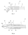
- FIG. 1 illustrates a soldering iron in accordance with the present invention having a replaceable tip.
- FIG. 2 is a longitudinal cross-sectional view of the soldering iron of FIG. 1 .
- FIG. 3 is an enlarged view of the tip area of FIG. 2 .
- FIG. 4( a ) is a side view of a tip having a recess.
- FIG. 4( b ) is a front view of the tip of FIG. 4( a ).
- FIG. 4( c ) is a base view of the tip of FIG. 4( a ).
- FIG. 5( a ) is a schematic view of a ceramic heater having temperature sensor and a heater.
- FIG. 5( b ) illustrates a ceramic sheet wrapped around a ceramic rod to form the ceramic heater.
- FIG. 5( c ) is a perspective view of a sleeve with a slit.
- FIG. 5( d ) is a cross-sectional view of a heater being press-fitted into a sleeve.
- FIG. 5( e ) is a cross-sectional view of heater, sleeve, and tip.
- FIG. 5( f ) is a cross-sectional view of a heater in a flush position with a sleeve.
- FIG. 5( g ) is a side view of a sleeve with a partial slit.
- FIG. 5( h ) is a front view of the sleeve of FIG. 5( g ).
- FIG. 5( i ) is an opposing side view of the sleeve of FIG. 5( g ) with a slit along the length of the sleeve.
- FIG. 5( j ) illustrates a sleeve divided into a plurality of portions.
- FIG. 5( k ) illustrates two portions of the sleeve being placed against a ceramic heater.
- FIG. 5( l ) illustrates the two portions of the sleeve being press fitted against a ceramic heater by a holding tube.
- FIG. 6( a ) is a graph of a temperature control curve for a conventional soldering iron.
- FIG. 6( b ) is a graph of a temperature control curve for a soldering iron in accordance with this invention.
- FIG. 7 is a cross-sectional view of a desoldering iron in accordance with this invention.
- FIG. 8 is a cross-sectional view an alternative desoldering iron in accordance with this invention.
- FIG. 9( a ) is an enlarged exploded view of a tip having a bore with a corresponding head protruding from the sleeve.
- FIG. 9( b ) is a view taken along line 9 ( b )- 9 ( b ) of FIG. 9( a ) showing the base of the tip.
- FIG. 9( c ) is a view taken along line 9 ( c )-( c ) of FIG. 9( a ) showing the face end of the sleeve.
- FIG. 9( d ) is an enlarged exploded view of a tip having an alternative bore with a corresponding head protruding from the sleeve.
- FIG. 9( e ) is a view taken along line 9 ( e )- 9 ( e ) of FIG. 9( d ) showing the base of the tip.
- FIG. 9( f ) is a view taken along line 9 ( f )-( f ) of FIG. 9( d ) showing the face end of the sleeve.
- FIG. 9( g ) is an enlarged exploded view of a tip having another alternative bore with a corresponding head protruding from the sleeve.
- FIG. 9( h ) is a view taken along line 9 ( h )- 9 ( h ) of FIG. 9( g ) showing the base of the tip.
- FIG. 9( i ) is a view taken along line 9 ( i )-( i ) of FIG. 9( g ) showing the face end of the sleeve.
- FIG. 10( a ) is an enlarged view of a tip having a bore.
- FIG. 10( b ) is an enlarged view of the sleeve with a head corresponding to the bore of FIG. 10( a ) where the head is in thermal contact with a temperature sensor protruding from the sleeve.
- FIG. 10( c ) is an enlarged view of a tip having an alternative bore.
- FIG. 10( d ) is an enlarged view of the sleeve with a head corresponding to the bore of FIG. 10( c ) where the head is in thermal contact with a temperature sensor protruding from the sleeve.
- FIG. 10( e ) is an enlarged view of a tip having another alternative bore.
- FIG. 10( f ) is an enlarged view of the sleeve with a head corresponding to the bore of FIG. 10( e ) where the head is in thermal contact with a temperature sensor protruding from the sleeve.
- FIG. 11 is a cross-sectional view of a conventional soldering iron.
- FIG. 1 illustrates a soldering iron generally at 10 having a heater cartridge assembly 11 and a removable and replaceable tip 4 protruding from the assembly.
- the tip 4 may be replaced with another tip as the tip wears out or when a different tip is better suited for a particular soldering operation.
- the soldering iron 10 includes a clamping ring or member 7 that releasably holds the heater cartridge assembly 11 to the casing 1 .
- the heater cartridge assembly 11 includes a locking tube 6 that retains the tip 4 such that the tip protrudes from the locking tube.
- the clamping ring 7 may be disengaged from the casing 1 to release the heater cartridge assembly 11 from the casing, and the tip 4 may then be released from the heater cartridge assembly 11 and replaced with another desired tip.
- FIG. 2 is a cross-sectional view of the soldering iron 10
- FIG. 3 is a close up view of the heater cartridge assembly area.
- the heater cartridge assembly 11 includes a sleeve 3 adapted to receive a heater 2 having a contact end 12 .
- the casing 1 has an opening with electrical leads adapted to electrically couple to the contact end 12 to provide power to the heater 2 .
- the heater 2 includes a heating element 2 a near the face end 3 a of the sleeve. The power through the contact end 12 is provided to the heating element 2 a to generate heat for melting solder.
- the sleeve 3 may be made from a material having high thermal transmissivity and substantially covers the circumferential periphery of the ceramic heater 2 and is in close contact with the ceramic heater 2 .
- the tip 4 is configured to releaseably couple to the face end 3 a of the sleeve 3 , whereby the tip 4 is near the heating element 2 a .
- the face end 3 a may have a circular face.
- the casing 1 may include a temperature control device 5 , at the interior of the casing 1 , to control the power provided to the heater 2 a , thereby controlling the temperature of the tip 4 .
- the heat generated by the heater 2 is conducted through the sleeve 3 to the face end 3 a and then to the tip 4 to melt the solder.
- the casing 1 may have a substantially tubular configuration made from metal or from a hard, heat-resistant synthetic resin; the circumferential periphery thereof is provided with a grip 1 a made of a heat insulating and elastic synthetic material.
- the casing 1 may be made of synthetic rubber so that an operator can grip the handle of the soldering iron 10 .
- the ceramic heater 2 may have a circular configuration made from ceramic and provided so as to generate heat for heating solder.
- the ceramic heater 2 can have a temperature sensor 2 b positioned near the face end 3 a with the heating element 2 a disposed between the sensor 2 b and the contact end 12 .
- a portion 2 c of the temperature sensor 2 b may protrude from the sleeve 3 and is sized to fit within the tip 4 as discussed below.
- FIGS. 4 ( a ), ( b ), and ( c ) illustrate the side view, front view, and base view of the tip 4 , respectively.
- FIG. 4( c ) illustrates the base of the heat-receiving face 4 c of the tip 4 , which may have a recess 4 b adapted to receive at least a portion of the temperature sensor 2 c .
- the recess 4 b is adapted to receive the front portion 2 c of the temperature sensor 2 b so that the heat-receiving face 4 c may make a thermal contact with the face end 3 a formed at the foreward end of the sleeve 3 .
- the heating element 2 a may make a thermal contact with the sleeve 3 so that heat from the heating element 2 a may conduct through the sleeve and the heat-receiving face 4 c and towards the edge 4 a of the tip 4 to heat and melt the solder on a substrate, such as a circuit board.
- the tip 4 may be made from a variety of materials known to one skilled in the art, such as copper, having a high thermal transmissivity.
- the tip 4 may be also iron plated to prevent erosion from occurring from the solder.
- the tip 4 may be chromium plated to prevent solder creep.
- FIG. 5( a ) illustrates a circuit of the heater 2 that may be formed by printing the circuit schematic on the ceramic sheet 2 d .
- the heat-generating resistor pattern of tungsten 2 a , or the like, and a temperature-sensing resistor pattern of tungsten 2 b , or the like may be printed onto a ceramic sheet 2 d .
- the ceramic sheet 2 d may be wrapped around a ceramic rod 2 e to form the heater 2 .
- the ceramic sheet 2 d including the temperature sensor 2 b and the heating element 2 a may be positioned near the surface of the heater 2 such as about 0.3 mm or between 0.1 mm and 0.5 mm from the surface of the heater 2 .
- the rod 2 e and the sheet 2 d may be bonded by heating both of them so that the temperature sensor 2 b is wrapped around the cylindrical ceramic rod 2 e , having a base of alumina or silicon nitride.
- the heating element 2 a and temperature sensor 2 b may be integrated to form the heater 2 .
- FIG. 5( c ) is a perspective view of a sleeve 3 having a longitudinal slit 3 c .
- the slit 3 c allows the sleeve 3 to radially expand and contract.
- the heater 2 formed from the ceramic rod 2 e preferably has sufficient stiffness and strength to be press-fitted into the sleeve 3 . This way, the heater 2 may form a more direct thermal contact with the sleeve 3 providing for efficient transfer of heat from the heating element 2 a to the sleeve 3 .
- the heater 2 may be press-fitted into the sleeve 3 of FIG. 5( c ) to allow at least a portion of the temperature sensor 2 b to protrude from the face end 3 a of the sleeve 3 .
- FIG. 5( d ) is a cross-sectional view of the heater 2 being press fitted into the sleeve 3 .
- the sleeve 3 may be placed over a mount 14 with a cavity 14 a having a predetermined depth.
- the fore end 2 f of the rod 2 e protrudes from the face end 3 a of the sleeve 3 at the predetermined depth to accurately control the distance that the temperature sensor protrudes from the sleeve.
- each heater cartridge 11 may be provided with the temperature sensor 2 b protruding from the face end 3 a of the sleeve 3 in a substantially similar manner.
- FIG. 5( e ) is a cross-sectional view of the heater cartridge 11 with the heater 2 press-fitted into the sleeve 3 with at least a portion of the temperature sensor 2 b protruding from the sleeve; the protruding portion being positioned in the recess 4 b of the tip 4 .
- the portion as illustrated by reference letter X in FIG. 5( e ) of the temperature sensor 2 b that is inserted into the recess 4 b may be between about 0.3 mm and 2.0 mm.
- the depth of the recess 4 b may be between about 1.5 mm and 5.0 mm, and in particular about 3.0 mm.
- the diameter of the recess 4 b may be between about 3.8 mm and about 4.3 mm.
- the control device 5 can monitor the temperature of the tip 4 and quickly adjust for the temperature difference between the tip 4 and a set value. Excessive temperature rises in the heating element 2 a are thereby minimized.
- FIG. 5( e ) shows that a gap may be formed between the fore end 2 f of the heater 2 and the tip 4 .
- the fore end 2 f may be configured so that a thermal contact may be made between the fore end 2 f and the tip 4 .
- the sleeve 3 may cover the circumferential periphery of the ceramic heater 2 and be in close contact with the ceramic heater to transmit the heat generated by the heating element 2 a of the ceramic heater to the soldering iron tip 4 with the temperature sensor 2 b being in close proximity with the tip 4 .
- the temperature sensor thereby can measure the temperature of the tip with minimal time delay.
- the sleeve 3 may be formed from silver or copper or other materials having high thermal transmissivity.
- the heater cartridge assembly 11 includes a holder tube 1 c adapted to receive the sleeve 3 to couple the sleeve and the heater 2 to the casing 1 .
- the holder tube 1 c may be sized and configured so that the sleeve 3 may be inserted and retained within the holder tube 1 c . Once the cartridge assembly is assembled, the holder tube 1 c may be positioned near the grip portion 1 a of the casing 1 . To minimize transfer of heat from the holder tube 1 c to the grip portion 1 a , the holder tube 1 c may be made of material having high thermal resistance or low thermal conductivity such as stainless steel. This way, a user may more comfortably grip the grip portion 1 a while operating the soldering iron.
- FIG. 5( f ) illustrates that the ceramic heater 2 may be fitted into the sleeve 3 to form a close thermal contact between the ceramic heater 2 and the sleeve without the temperature sensor 2 b protruding from the sleeve.
- a direct thermal contact may be formed between the ceramic heater 2 and the sleeve 3 by press fitting the heater 2 into the opening of the sleeve until the end of the ceramic heater 2 is flush with the end of the sleeve 3 , as illustrated in FIG. 5( f ).
- the tip 4 may be provided without the recess 4 b such that the heat receiving face 4 c may be a solid surface to form a thermal contact with the end of the ceramic heater 2 and the heat transfer face end 3 a of the sleeve 3 .
- the heat generated by the ceramic heater 2 ray efficiently conduct through the sleeve 3 and then to the heat receiving face 4 c of the tip 4 .
- the temperature sensor 2 b may be provided adjacent or near the heat receiving face 4 c to measure the temperature of the tip 4 with minimal delay.
- FIGS. 5( g ) through 5 ( i ) illustrate that the sleeve 3 may have a plurality of slits (or slots) to allow the sleeve 3 to expand while the ceramic heater 2 is being press fitted into the opening of the sleeve 3 .
- FIG. 5( g ) illustrate that on one side of the sleeve 3 a partial slit 3 d may be formed that does not pass through the heat transfer face end 3 a of the sleeve 3 .
- FIG. 5( i ) shows another slit 3 c that passes through the entire length of the sleeve 3 .
- the sleeve 3 thereby, while unitary, can expand and contract along the slits 3 c and 3 d to receive the ceramic heater 2 so that a direct thermal contact may be formed between the sleeve 3 and the ceramic heater 2 .
- the sleeve 3 may have a number of slits to allow the sleeve 3 to expand and contract to receive the ceramic heater 2 and then form a thermal contact with the ceramic heater 2 .
- the sleeve 3 may have three or four slits with two or three partial slits and one slit along the entire length of the sleeve.
- a slit may also run diagonally between the two opposing ends of the sleeve 3 .
- FIGS. 5( j ), 5 ( k ) and 5 ( l ) illustrate a ceramic heater 2 being sandwiched by a first portion 3 e and a second portion 3 f of the sleeve 3 .
- the two portions 3 e and 3 f of the sleeve 3 are then press-fitted against the ceramic heater 2 by a holding tube 1 c .
- FIG. 5( j ) illustrates that the sleeve 3 may be provided in a plurality of pieces such as in two portions 3 e and 3 f .
- the inner-arc area 3 g of the two portions 3 e and 3 f may substantially conform to the outer diameter of the ceramic heater 2 .
- the inner-arc area 3 g and the outer surface of the two portions 3 e and 3 f may be easily treated or plated to substantially prevent oxidization from forming between the two portions 3 e and 3 f of the sleeve 3 and the ceramic heater 2 due to high temperature therein.
- the two portions 3 e and 3 f may be treated or plated to improve the thermal contact between the two portions 3 e and 3 f and the ceramic heater 2 .
- FIGS. 5( k ) and 5 ( l ) illustrate a method in which the two portions 3 e and 3 f of the sleeve 3 may be press-fitted against the ceramic heater 2 without scratching or damaging the plating on the inner-arc area 3 g of the two portions 3 e and 3 f .
- FIG. 5( k ) illustrates the forward end 2 f of the ceramic heater 2 placed inside the cavity 14 a of the mount 14 such that a portion of the temperature sensor 2 b is within the cavity 14 a .
- the two portions 3 e and 3 f of the sleeve 3 are then placed against the ceramic heater 2 .
- the outer diameter of the two portions 3 e and 3 f may be substantially similar or slightly larger than the inner diameter of the holding tube 1 c .
- the two portions 3 e and 3 f may be press-fitted against the ceramic heater 2 .
- a plating layer within the inner-arc area 3 g of the two portions 3 e and 3 f is substantially preserved so that good thermal contact may be formed between the ceramic heater 2 and the two portions 3 e and 3 f of the sleeve 3 .
- the sleeve 3 may have a beveled edge 3 h on the opposite end of the heat transfer facing end 3 a so that when the holding tube 1 c is press-fitted over the two portions 3 e and 3 f , the beveled edge 3 h assists in fitting the holding tube 1 c over the two portions 3 e and 3 f.
- the sleeve 3 may be divided into a number of portions such as two portions 3 e and 3 f . Alternatively, the sleeve 3 may be divided into three or more portions.
- the sleeve 3 described in 5 ( j ) may be fitted with the ceramic heater 2 as illustrated in FIG. 5( f ) such that the fore-ends of the sleeve 3 and the ceramic heater 2 are flush with respect to each other.
- FIGS. 2 and 3 illustrate that the tip 4 may be configured to have a locking member 4 d along the edge of the base 4 c to engage with a reduced-diameter end section 6 a of a locking tube 6 .
- the locking tube 6 may be formed of metal with a circumferential periphery to fit over the sleeve 3 .
- the locking tube 6 has an outer aft end 6 b that expands so that the diameter of the outer end 6 b is greater than the diameter of the body of the locking tube 6 .
- the tip 4 may be inserted into the locking tube 6 through the opening formed on the outer aft end 6 b of the locking tube 6 .
- the fore end 2 c of the ceramic heater 2 protruding from the sleeve 3 may be inserted behind the tip so that once the cartridge assembly 11 is assembled, the base 4 c of the tip 4 may form a thermal contact with the face end 3 a of the sleeve 3 .
- the clamping ring 7 may have a threaded section 7 b adapted to engage with the threaded section 1 b formed on the forward end of the casing 1 .
- the clamping ring 7 may be placed over the heater cartridge assembly 11 and the threaded section 7 b may be rotated to engage with the threaded section 1 b of the casing 1 .
- the clamping ring 7 may have a retaining member 7 a with a smaller diameter configured to secure the aft end 6 b of the locking tube 6 with the foreward end of the threaded section 1 b .
- Securing the locking tube 6 with the casing 1 also secures the tip 4 to the face end 3 a of the sleeve 3 to form a thermal contact between the base 4 c of the tip and the face end 3 a of the sleeve 3 . Thereby, heat generated from the heating element 2 a may be conducted to the sleeve and to the tip 4 .
- the casing 1 may include a temperature control device 5 capable of controlling the temperature of the tip 4 by varying the current or power provided to the heating element 2 a .
- the temperature control device 5 may vary the current based on the difference between the value of the temperature measured by the temperature sensor 2 b and the set temperature value of the tip 4 .
- FIG. 5( a ) illustrates that the temperature control device 5 may be electrically coupled to the temperature sensor 2 b and the heating element 2 a .
- the control device 5 is also connected to a power source 8 by way of an electrical cord 1 d as shown in FIG. 1 .
- the temperature of the tip 4 may be measured by detecting the potential difference from the temperature sensor 2 b .
- the temperature of the tip 4 may be controlled so that the temperature of the tip 4 is substantially equal to the set temperature value by varying the current to the heating element 2 a with the ON/OFF control based on the potential difference between the measured temperature value and the set temperature value.
- the control device 5 may apply full current when the temperature of the tip which sensor 2 b measures is below the set temperature value to quickly restore the temperature of the tip 4 .
- FIG. 3 illustrates that if the edge 4 a of the soldering iron tip 4 becomes worn or if a different soldering tip is desired for a particular soldering application, the tip 4 may bet replaced.
- the tip 4 may be replaced by rotating or unscrewing the clamping ring 7 to disengage the threaded section 7 b from the threaded section 1 b provided on the foreward end of the casing 1 , thereby releasing the heating cartridge assembly 11 from the casing 1 .
- the heating cartridge assembly 11 may be disassembled by removing the locking tube 6 to expose the soldering tip 4 and the holding tube 1 c .
- the old tip 4 may be removed from the fore end 2 c of the ceramic heater 2 , and a new tip fitted into the fore end 2 c of the ceramic heater 2 such that at least a portion of the temperature sensor 2 b is fitted inside the recess 4 b of the new tip. As such, only the tip 4 is replaced instead of the entire tip and the sleeve combination being replaced to minimize the cost of operating the soldering iron 10 .
- the heater cartridge assembly 11 may be reassembled by positioning the locking tube 6 over the tip and the ceramic heater 2 .
- the heater cartridge assembly may be coupled to the casing 1 by placing the clamping ring over the heater cartridge assembly and rotating the clamping ring 7 until the threaded sections 7 b and 1 b are secured together.
- the sleeve 3 substantially covers the heater 2 to form a thermal contact between the sleeve 3 and the heater 2 .
- the outer configuration of both the heater 2 and the sleeve 3 may have a circular (or cylindrical) shape.
- the sleeve 3 may have a circular opening adapted to receive the heater 2 having a circular shape to form a close thermal contact between the sleeve and the heater.
- Both the heater 2 and the sleeve 3 may be elongated to form a large thermal contact area to efficiently transfer heat from the heater to the sleeve.
- the heat-receiving face 4 c is configured to form a thermal contact with the annular heat-transfer face 3 a provided at the foreward end face of the sleeve 3 ; and the recess 4 b is configured to form a thermal contact with at least the portion 2 c of the temperature sensor 2 b to provide a large thermal contact area between the tip 4 and the heater 2 .
- an efficient heat transfer is made from the heater 2 to the tip 4 .
- the sleeve 3 may be made of a variety of heat conductive materials such as silver and copper.
- the heating element 2 a may be made of tungsten or other material which efficiently converts electrical current to heat.
- FIGS. 6( a ) and ( b ) illustrate temperature control characteristics of two soldering irons.
- FIG. 6( a ) shows a temperature control curve for a conventional soldering iron; and
- FIG. 6( b ) shows a temperature control curve for a soldering iron 10 in accordance with the present invention.
- the temperature control devices for both soldering irons were controlled by varying the current to its heating element with ON/OFF control, and the temperature of the tips for both soldering irons were set at 350° C.
- a soldering iron of the same type as disclosed in JP-11-506054-A described above and whose entire contents are hereby incorporated by reference (“the conventional soldering iron”) was used to measure the temperature control characteristics.
- the tip contacts the free end of the sleeve 3 , rather than being mated with the foreward end of the ceramic heater.
- the heat transmission from the sleeve to the soldering iron tip and thereby the thermal efficiency of the soldering iron are poor.
- after the conventional soldering iron is turned on it may take approximately thirty seconds for the temperature of the tip to stabilize at the set temperature.
- the conventional soldering iron has a gap between the temperature sensor and the heating element, and another gap between the heating element and the tip. Because of these gaps, the temperature sensor lags behind in measuring the temperature of the tip. As such, the control device is slow to maintain the temperature of the tip at the set value. For instance, when the conventional soldering tool is initially turned on, the delay in measuring the temperature of the tip causes an excessive temperature rise in the heating element and the tip, and as illustrated in FIG. 6( a ), an overshoot of approximately 10° C. is produced in the tip.
- the heat transfer face 3 a forms a good thermal contact with the fore end 2 c of the ceramic heater 2 , so that the heat transfer between the temperature sensor 2 b and the tip 4 is more efficient than the conventional soldering iron.
- the distance between the temperature sensor 2 b and the heating element 2 a and the soldering iron tip 4 is smaller than that of the conventional soldering iron to minimize the time the temperature sensor takes to measure the temperature of the tip. This is done, for example, by inserting at least a portion of the temperature sensor 2 b into the recess 4 b of the tip 4 . As illustrated in FIG.
- soldering iron 10 in accordance with this invention when the soldering iron 10 in accordance with this invention is initially turned on, it takes approximately fifteen seconds for the tip temperature to stabilize at the set temperature.
- the soldering iron 10 operates more efficiently because the overshoot is about 1° C. over the set value versus 10° C. in the conventional soldering iron, as shown in FIGS. 6( a ) and 6 ( b ). This means that less power is needed to reach the operating temperature with the soldering iron 10 than with the conventional soldering iron.
- the grip 1 a positioned near the heater 2 , is exposed to lower temperatures so that a user may more comfortably handle the soldering iron 10 .
- the length of the soldering iron 10 may be shortened so that the soldering iron 10 may be handled more easily.
- FIG. 7 is a cross-sectional view of a soldering iron shown generally at 20 of the present invention adapted for a desoldering operation.
- the soldering iron 20 includes a tip shown generally at 24 and having a suction pipe 24 a adapted to couple to a vacuum source, not shown, in FIG. 7 .
- the sleeve 3 is adapted to couple the tip 24 in a tangential relationship with the heater 2 .
- the tip 24 also has a nozzle 24 b capable of heating and melting solder on a substrate and removing the melted solder by vacuum suction through the nozzle 24 b and the suction pipe 24 a.
- FIG. 8 is a cross-sectional view of a soldering iron shown generally at 30 and adapted for a desoldering operation.
- the soldering iron 30 has a suction pipe 34 a that is coupled to a vacuum source, not shown in FIG. 8 .
- the soldering iron 30 has a nozzle 34 b capable of heating and melting solder on a substrate and removing the melted solder through an opening in the nozzle 34 b and through the suction pipe 34 a .
- the nozzle 34 b may be formed on the sleeve 3 , where the nozzle 34 b is substantially aligned with the longitudinal direction of the suction pipe 34 a.
- FIGS. 9( a )- 9 ( c ) illustrate the heat-receiving face 4 c of the tip 4 having a bore 4 e along with the recess 4 b discussed above.
- the bore 4 e may have a configuration adapted to receive a head 3 b ( FIG. 9( c )) protruding from the heat transfer face 3 a of the sleeve 3 .
- the combination of the bore 4 e and head 3 b engages the tip 4 with the sleeve 3 at a predetermined orientation.
- the combination of the bore 4 e and the head 3 b also provides additional thermal contact area between the tip and the sleeve.
- the replacement tips may be also provided with a bore to orient the replacement tip in the substantially similar manner as the original tip 4 with respect to the sleeve 3 .
- FIGS. 9( d ) through 9 ( i ) illustrate that the heat-receiving face 4 c may have a bore with a variety of configurations adapted to receive a corresponding head protruding from the heat transfer face 3 a of the sleeve 3 .
- FIGS. 9( d ) through 9 ( f ) illustrate the heat-receiving face 4 c having a bore 4 e forming a “T” configuration adapted to receive the corresponding head 3 b having a protrusion also in the form of a “T” configuration.
- FIGS. 9( g ) through 9 ( i ) illustrate the heat-receiving face 4 c having a bore 4 e in the form of a half-circle configuration adapted to receive the corresponding head 3 b having a protrusion also in the form of a half-circle configuration.
- FIG. 10( a ) illustrates that the head 3 b may protrude from the heat transfer face 3 a along the side of the temperature sensor 2 c .
- the tip 4 may have a corresponding bore 4 c along the heat-receiving face 4 c adapted to receive the head 3 b .
- the head 3 b is in thermal contact with the temperature sensor 2 c that provides additional surface area to make thermal contact between the temperature sensor 2 c and the tip 4 . This allows the temperature sensor 2 c to quickly detect the temperature of the tip with minimal delay.
- FIGS. 10( c ) through 10 ( f ) illustrate that a plurality of heads 3 b may protrude from the heat transfer face 3 a which are in contact with the temperature sensor 2 c to provide additional surface areas to make thermal contact between the temperature sensor 2 c and the tip 4 .
- the configuration of the head 3 b and the number of heads provided on the heat transfer face 3 a may vary, and other combinations of bore and head may be formed on the tip and the sleeve to provide a good thermal contact therebetween.
- the bore may be formed within the heat transfer face 3 a and the corresponding head formed on the heat receiving face 4 c .
- a plurality of spaced teeth on the heat transfer face which interlock or mate with a plurality of spaced teeth on the heat receiving face may be provided to increase the thermal contact area between the temperature sensor 2 b and the tip.
Abstract
Description
Claims (12)
Applications Claiming Priority (3)
| Application Number | Priority Date | Filing Date | Title |
|---|---|---|---|
| JPAPP-2003-191852 | 2003-04-07 | ||
| JP2003-191852 | 2003-07-04 | ||
| JP2003191852 | 2003-07-04 |
Publications (2)
| Publication Number | Publication Date |
|---|---|
| US20040232132A1 US20040232132A1 (en) | 2004-11-25 |
| US7679032B2 true US7679032B2 (en) | 2010-03-16 |
Family
ID=33432355
Family Applications (1)
| Application Number | Title | Priority Date | Filing Date |
|---|---|---|---|
| US10/874,856 Active US7679032B2 (en) | 2003-07-04 | 2004-06-22 | Soldering or desoldering iron |
Country Status (10)
| Country | Link |
|---|---|
| US (1) | US7679032B2 (en) |
| EP (1) | EP1493523B1 (en) |
| KR (1) | KR101111449B1 (en) |
| CN (2) | CN1575900A (en) |
| AT (1) | ATE378136T1 (en) |
| DE (1) | DE602004009998T2 (en) |
| DK (1) | DK1493523T3 (en) |
| ES (1) | ES2293126T3 (en) |
| PL (1) | PL1493523T3 (en) |
| PT (1) | PT1493523E (en) |
Cited By (15)
| Publication number | Priority date | Publication date | Assignee | Title |
|---|---|---|---|---|
| US20100065405A1 (en) * | 2008-02-06 | 2010-03-18 | Laitram, L.L.C. | Apparatus for sensing conditions local to a conveyor belt |
| US20110073583A1 (en) * | 2009-09-25 | 2011-03-31 | Antang Liu | Soldering Equipment |
| US20140166730A1 (en) * | 2012-12-13 | 2014-06-19 | Sage Electrochromics, Inc. | ULTRASONIC SOLDERING PROCESS FOR ELECTRICALLY POWERED IGUs |
| US9168605B2 (en) | 2012-04-17 | 2015-10-27 | Hakko Corporation | Soldering assembly for detachable tip |
| USD776935S1 (en) * | 2014-05-12 | 2017-01-24 | Ensitech IP Pty Limited | Electrolytic brush |
| USD777442S1 (en) * | 2014-05-12 | 2017-01-31 | Ensitech IP Pty Limited | Electrolytic brush |
| US20180361421A1 (en) * | 2017-06-16 | 2018-12-20 | Fenghua Weilder Electric Appliance Co., Ltd. | Heating device for hot melt glue gun |
| USD852596S1 (en) | 2017-10-26 | 2019-07-02 | Milwaukee Electric Tool Corporation | Soldering tool |
| US11110533B2 (en) | 2016-10-26 | 2021-09-07 | Milwaukee Electric Tool Corporation | Soldering tool |
| USD935500S1 (en) * | 2020-11-30 | 2021-11-09 | Qing Li | Digital display soldering iron |
| USD951317S1 (en) * | 2021-06-14 | 2022-05-10 | Junqiang Li | Soldering iron |
| USD960947S1 (en) * | 2020-11-17 | 2022-08-16 | Thermacut, K.S. | Plasma torch handle |
| US20230070160A1 (en) * | 2021-09-03 | 2023-03-09 | Qian Gou | Soldering iron device |
| USD995246S1 (en) * | 2021-08-23 | 2023-08-15 | Guangzhou Yihua Electronic Equipment Co., Ltd. | Heating system for desoldering iron |
| USD1006080S1 (en) * | 2022-09-15 | 2023-11-28 | Chengming Ding | Digital soldering iron |
Families Citing this family (25)
| Publication number | Priority date | Publication date | Assignee | Title |
|---|---|---|---|---|
| US8237091B2 (en) | 2002-11-26 | 2012-08-07 | Hakko Corporation | Soldering iron with replaceable tip |
| US7030339B2 (en) * | 2002-11-26 | 2006-04-18 | Hakko Corporation | Soldering iron tip with metal particle sintered member connected to heat conducting core |
| US20050011876A1 (en) * | 2002-11-26 | 2005-01-20 | Takashi Uetani | Soldering iron with replaceable tip cap |
| CN1575900A (en) | 2003-07-04 | 2005-02-09 | 白光株式会社 | Solder heating tool |
| US20060113352A1 (en) * | 2004-10-13 | 2006-06-01 | Hyperion Innovations, Inc. | Grips for handheld power tool |
| US20060169744A1 (en) * | 2005-02-01 | 2006-08-03 | Pace, Incorporated | Soldering tip with wear-and corrosion resistant coating |
| US7807949B2 (en) * | 2006-02-28 | 2010-10-05 | Hakko Corporation | Locking mechanism for soldering iron |
| US7633039B2 (en) | 2006-08-31 | 2009-12-15 | Infineon Technologies Ag | Sensor device and a method for manufacturing the same |
| KR100855027B1 (en) * | 2007-04-17 | 2008-08-28 | 주식회사엑소 | Soldering iron |
| US8420980B2 (en) * | 2007-11-26 | 2013-04-16 | Kyocera Corporation | Ceramic heater, oxygen sensor and hair iron that uses the ceramic heater |
| US8274011B2 (en) * | 2009-01-24 | 2012-09-25 | Hakko Corporation | Soldering device and method of making same |
| CN102179590A (en) * | 2010-10-26 | 2011-09-14 | 苏州瀚德光伏科技有限公司 | Electric soldering bit |
| JP5546436B2 (en) * | 2010-12-07 | 2014-07-09 | 株式会社ジャパンユニックス | Soldering iron |
| KR102040193B1 (en) * | 2013-03-14 | 2019-11-04 | 삼성에스디아이 주식회사 | Soldering iron |
| US9700951B2 (en) * | 2014-05-28 | 2017-07-11 | Hakko Corporation | Heater sensor complex with high thermal capacity |
| CN105710477B (en) * | 2014-12-19 | 2018-03-16 | 白光株式会社 | Solder removes system |
| CN105848317B (en) * | 2015-01-13 | 2022-05-17 | 深圳市新宜康科技股份有限公司 | Intelligent temperature control heating device and preparation method thereof |
| CN104812108A (en) * | 2015-04-02 | 2015-07-29 | 徐东元 | Electric soldering iron and application of electric soldering iron for removing fat in anatomy specimen preparation |
| DE102018102792B3 (en) * | 2018-02-08 | 2019-05-09 | Ersa Gmbh | Electric soldering device, in particular soldering iron |
| CN112188944B (en) | 2018-04-02 | 2022-07-01 | 艾沛克斯品牌公司 | Intelligent welding end |
| USD865014S1 (en) * | 2019-08-14 | 2019-10-29 | Xinning Xu | Digital display soldering iron |
| USD918974S1 (en) * | 2019-10-17 | 2021-05-11 | Apex Brands, Inc. | Soldering iron handle |
| USD879169S1 (en) * | 2019-10-28 | 2020-03-24 | Qiuxian Xu | Electric soldering iron |
| US20220226919A1 (en) * | 2021-01-15 | 2022-07-21 | Ok International, Inc. | Soldering iron including temperature profiling and method of use |
| DE102021210673A1 (en) | 2021-09-24 | 2023-03-30 | Robert Bosch Gesellschaft mit beschränkter Haftung | Electric soldering iron |
Citations (140)
| Publication number | Priority date | Publication date | Assignee | Title |
|---|---|---|---|---|
| US29039A (en) | 1860-07-03 | Improvement in soldering-i rons | ||
| US53545A (en) | 1866-03-27 | Improvement in soldering-irons | ||
| US62941A (en) | 1867-03-19 | Improved soldering-ibon | ||
| US73798A (en) | 1868-01-28 | Improvement in the construction of soldering-iron | ||
| US154077A (en) | 1874-08-11 | Improvement in soldering apparatus | ||
| US573245A (en) | 1896-12-15 | Paul stotz | ||
| US1098437A (en) * | 1911-09-13 | 1914-06-02 | William S Hadaway Jr | Electric heating device. |
| US1350181A (en) | 1918-04-24 | 1920-08-17 | Remane Hermann | Soldering-iron |
| US1667618A (en) | 1924-01-08 | 1928-04-24 | Gen Electric | Soldering iron |
| US2213438A (en) | 1938-11-08 | 1940-09-03 | Leonard P Young | Soldering iron construction |
| US2390498A (en) | 1941-12-12 | 1945-12-11 | Emil R Capita | Apparatus and method for applying solder |
| US2582481A (en) | 1950-12-16 | 1952-01-15 | Western Electric Co | Temperature-controlled soldering iron |
| US2679223A (en) | 1949-09-16 | 1954-05-25 | Edmond G Franklin | Soldering instrument |
| US2689901A (en) | 1952-01-05 | 1954-09-21 | Solder Weld Corp | Soldering tool |
| US2751484A (en) | 1955-06-22 | 1956-06-19 | Moon Thomas Elmer | Electric soldering iron |
| US2908796A (en) | 1956-11-27 | 1959-10-13 | Western Electric Co | Electrical solder pot |
| US2982838A (en) | 1959-09-01 | 1961-05-02 | Robertshaw Fulton Controls Co | Thermostatically controlled soldering iron |
| US3037274A (en) | 1957-03-06 | 1962-06-05 | Western Electric Co | Methods of and apparatus for mass soldering wiring boards |
| US3188448A (en) | 1963-05-20 | 1965-06-08 | Carl E Weller | Soldering iron having temperature control means |
| US3211354A (en) | 1962-04-13 | 1965-10-12 | Dugard Robert Evers | Apparatus for desoldering |
| US3245599A (en) | 1960-06-20 | 1966-04-12 | Hexacon Electric Company | Soldering tip for electric soldering irons |
| US3269633A (en) | 1964-11-04 | 1966-08-30 | Sanders Associates Inc | Automatic spin soldering machine |
| US3315350A (en) | 1963-12-27 | 1967-04-25 | Plato Products Inc | Method of manufacturing replaceable soldering iron tips |
| US3358897A (en) | 1964-03-31 | 1967-12-19 | Tempress Res Co | Electric lead wire bonding tools |
| US3429024A (en) * | 1966-06-20 | 1969-02-25 | Gennaro Scamberti Jr | Method for manufacturing soldering iron tips |
| US3443733A (en) | 1967-01-11 | 1969-05-13 | Alexander A Parente | Soldering and desoldering tool |
| US3578948A (en) | 1969-03-19 | 1971-05-18 | Gen Electric | Soldering and desoldering hand tool employing air blast or suction |
| US3584190A (en) | 1970-02-27 | 1971-06-08 | Texas Instruments Inc | Self-regulating heat applicator |
| US3627191A (en) | 1968-03-18 | 1971-12-14 | Jesse Carl Hood Jr | Solder wick |
| US3646577A (en) * | 1970-03-30 | 1972-02-29 | Ncr Co | Temperature-controlled soldering tool |
| GB1284994A (en) | 1970-01-14 | 1972-08-09 | Gen Electric Co Ltd | Improvements in or relating to soldering irons |
| US3699306A (en) * | 1971-03-01 | 1972-10-17 | Gen Electric | Temperature controlled soldering iron |
| US3715797A (en) | 1970-10-23 | 1973-02-13 | Wik It Electronics Corp | Method for solder removal |
| US3716692A (en) * | 1970-07-16 | 1973-02-13 | R Mackie | Temperature controlled soldering irons |
| JPS4867025U (en) | 1971-12-06 | 1973-08-25 | ||
| US3770937A (en) * | 1970-12-22 | 1973-11-06 | M Smits | Temperature controlled electric hand soldering iron |
| US3804320A (en) | 1972-09-13 | 1974-04-16 | Nu Concept Computer Syst Inc | Pack extractor |
| US3818539A (en) | 1973-05-25 | 1974-06-25 | Fortune William S | Desoldering implement |
| US3834604A (en) | 1972-10-03 | 1974-09-10 | Western Electric Co | Apparatus for solid-phase bonding mating members through an interposed pre-shaped compliant medium |
| US3876857A (en) | 1973-06-29 | 1975-04-08 | Raymond Lee Organization Inc | Soldering pen for microcircuit production |
| US3883716A (en) | 1971-03-08 | 1975-05-13 | William S Fortune | Temperature controlled soldering instrument |
| US3884409A (en) | 1973-11-08 | 1975-05-20 | Harry Kaufman | Hand operated desoldering device |
| US3899114A (en) * | 1974-11-04 | 1975-08-12 | Newman M M Corp | Soldering iron tip and method of fabrication |
| DE2412143A1 (en) | 1974-03-13 | 1975-09-25 | Krone Gmbh | Portable universal power tool - has housing with accumulators in series or parallel connectable to portable transformer accepting tool housing |
| US3919524A (en) | 1973-08-16 | 1975-11-11 | William S Fortune | Soldering tip and locking apparatus combination |
| US3941299A (en) | 1974-08-26 | 1976-03-02 | Engelhard Minerals & Chemicals Corporation | Method of brazing Cu alloys to Ag-Cdo alloys |
| US3943326A (en) | 1972-11-24 | 1976-03-09 | Royel International Pty. Ltd. | Temperature control circuit for a hand held soldering tool |
| US3990623A (en) * | 1975-03-28 | 1976-11-09 | Fortune William S | Holder system for soldering instrument |
| US4023724A (en) | 1971-09-17 | 1977-05-17 | Stanley Electric Co., Ltd. | Soler removing bit |
| US4034202A (en) | 1975-05-23 | 1977-07-05 | Nu-Concept Computer Systems, Inc. | Integrated circuit pack extractor |
| US4035613A (en) * | 1976-01-08 | 1977-07-12 | Kyoto Ceramic Co., Ltd. | Cylindrical ceramic heating device |
| US4055744A (en) * | 1975-07-16 | 1977-10-25 | Fortune William S | Electrically heated soldering-desoldering instruments |
| US4064447A (en) | 1975-08-25 | 1977-12-20 | Disston, Inc. | Cordless portable electrically powered device |
| US4090517A (en) * | 1976-07-01 | 1978-05-23 | Nagatoki Takenaka | Medical appliance |
| US4133291A (en) | 1976-04-30 | 1979-01-09 | Ernst Spirig | Apparatus for flux coating metal wick |
| US4137369A (en) | 1977-05-03 | 1979-01-30 | Wik-It Electronics Corporation | Visual dye indicator of solder wicking action in metal coated copper braid |
| US4164606A (en) | 1977-11-08 | 1979-08-14 | Ernst Spirig | Tinned copper braids for solder removing |
| US4191917A (en) | 1977-08-25 | 1980-03-04 | Disston, Inc. | Battery pack rechargeable in recessed or flush-type receptacles |
| US4206864A (en) | 1977-06-23 | 1980-06-10 | Rauchwerger George P | Electrically heated high speed de-soldering tool |
| US4416408A (en) | 1981-05-22 | 1983-11-22 | Ernst Spirig | Solder removing device |
| GB2148676A (en) | 1983-10-17 | 1985-05-30 | Eldon Ind Inc | Ceramic heater having temperature sensor integrally formed thereon |
| US4553021A (en) | 1982-05-10 | 1985-11-12 | Gianfranco Conti | Pincer-gun for electrically heating metal hinges of thermoplastic eyeglass frames |
| US4560101A (en) | 1983-06-16 | 1985-12-24 | Cooper Industries, Inc. | Self-locking, removeable tapered tips for soldering and de-soldering tools |
| US4562337A (en) | 1984-05-30 | 1985-12-31 | Eldon Industries, Inc. | Solder pot |
| US4568819A (en) | 1982-12-20 | 1986-02-04 | General Electric Company | Pressure-sensitive electric soldering/desoldering tool |
| US4698774A (en) | 1984-10-02 | 1987-10-06 | Kabushiki Kaisha Tamura Seisakusho | Method of and apparatus for controlling automatic soldering system |
| US4745264A (en) | 1984-03-06 | 1988-05-17 | Metcal, Inc. | High efficiency autoregulating heater |
| US4775776A (en) | 1983-02-28 | 1988-10-04 | Electrovert Limited | Multi stage heater |
| US4779786A (en) | 1986-04-29 | 1988-10-25 | Pace Incorporated | Desoldering device |
| US4779790A (en) | 1985-08-08 | 1988-10-25 | Pace Incorporated | Job oriented method and apparatus utilizing molten solder for procedures such as soldering and desoldering |
| US4795886A (en) | 1986-12-19 | 1989-01-03 | Metcal, Inc. | Temperature control in which the control parameter is the degree of imperfection in the impedance matching |
| US4830260A (en) | 1986-12-23 | 1989-05-16 | Plato Products, Inc. | Soldering iron tip |
| US4839501A (en) | 1984-12-21 | 1989-06-13 | Metcal, Inc. | Cartridge soldering iron |
| US4877944A (en) | 1987-06-08 | 1989-10-31 | Metcal, Inc. | Self regulating heater |
| US4891497A (en) | 1988-04-02 | 1990-01-02 | Hakko Metal Industries Limited | Soldering iron temperature regulator |
| US4903884A (en) | 1987-12-17 | 1990-02-27 | Royel International Pty. Ltd. | Soldering apparatus |
| US4924067A (en) | 1987-02-24 | 1990-05-08 | Cooper Industries, Inc. | Temperature controlled soldering resistor to change the set temperature |
| US4945210A (en) | 1987-11-18 | 1990-07-31 | Hakko Metal Industries Limited | Card controlled soldering iron temperature control device |
| EP0386948A1 (en) | 1989-03-09 | 1990-09-12 | OGLESBY & BUTLER, RESEARCH & DEVELOPMENT LIMITED | A soldering head for a soldering or desoldering iron |
| US4997121A (en) | 1989-06-29 | 1991-03-05 | Hakko Corporation | Nozzle of solder suction device |
| US5007574A (en) | 1989-09-14 | 1991-04-16 | Metcal, Inc. | Desoldering device |
| US5014210A (en) | 1989-03-06 | 1991-05-07 | Postlewait Lester B | Microprocessor controlled soldering station |
| US5023848A (en) | 1989-05-15 | 1991-06-11 | Highes Aircraft Company | Solder wave dwell timer |
| US5033785A (en) | 1990-04-20 | 1991-07-23 | Woolley Jr William J | Clamp mechanism |
| US5059769A (en) * | 1991-02-22 | 1991-10-22 | Fortune William S | Replaceable soldering tip assembly |
| US5062564A (en) | 1989-11-28 | 1991-11-05 | Cooper Industries | Rapid response soldering station |
| US5083698A (en) | 1990-02-26 | 1992-01-28 | Solder Removal Company | Vacuum tip surmo-wick removal system |
| US5094139A (en) | 1990-02-26 | 1992-03-10 | Solder Removal Company | Desoldering braid |
| US5122637A (en) | 1991-01-11 | 1992-06-16 | Wellman Thermal Systems Corporation | Temperature controlled soldering iron having low tip leakage voltage |
| US5151574A (en) | 1989-10-18 | 1992-09-29 | Cooper Industries, Inc. | Electric soldering iron with plug-in tip temperature sensor |
| US5170024A (en) | 1990-03-28 | 1992-12-08 | Sharp Kabushiki Kaisha | Heat cooking apparatus with photoconductive element and thermistor |
| US5182427A (en) | 1990-09-20 | 1993-01-26 | Metcal, Inc. | Self-regulating heater utilizing ferrite-type body |
| US5297717A (en) | 1993-04-05 | 1994-03-29 | Pace Incorporated | Self-aligning tip elements for tweezer-type soldering handpiece |
| US5305941A (en) | 1992-12-28 | 1994-04-26 | Plato Products, Inc. | Desoldering wick |
| US5326016A (en) | 1993-04-15 | 1994-07-05 | Cohen Marvin S | Method for removing electrical components from printed circuit boards |
| US5329085A (en) | 1992-08-05 | 1994-07-12 | Metcal, Inc. | Temperature self regulating heaters and soldering irons |
| US5395046A (en) | 1993-10-25 | 1995-03-07 | Nordson Corporation | Hand-held spray gun with replaceable handle |
| US5402563A (en) | 1992-08-28 | 1995-04-04 | Hitachi, Ltd. | Apparatus for removing electronic device from printed circuit board |
| US5408072A (en) | 1994-02-02 | 1995-04-18 | American Hakko, Inc. | Variable temperature high frequency induction heating soldering iron |
| US5412178A (en) | 1993-07-23 | 1995-05-02 | Japan Bonkote Company Limited | Iron-tip temperature detector of electric soldering iron |
| US5446262A (en) | 1994-04-19 | 1995-08-29 | Wahl Clipper Corporation | Soldering iron and soldering iron tip with spaced heatable shell member |
| US5495093A (en) | 1993-02-05 | 1996-02-27 | Edsyn, Inc. | Soldering apparatus processor having temperature selection, calibration and heating control of tip |
| US5553767A (en) | 1994-08-17 | 1996-09-10 | Donald Fegley | Soldering iron tip made from a copper/iron alloy composite |
| US5572119A (en) | 1994-10-28 | 1996-11-05 | Barber-Colman Company | Eddy current position sensor including an insulating base having conductive surfaces for electrically connecting a coil to the lead wires |
| WO1997026108A1 (en) * | 1996-01-17 | 1997-07-24 | Cooper Tools Gmbh | Soldering iron |
| US5683603A (en) | 1995-04-19 | 1997-11-04 | Fortune; William S. | Electric soldering iron tip improvements |
| US5746367A (en) | 1996-04-08 | 1998-05-05 | Ceridan Corporation | Method and apparatus to wick solder from conductive surfaces |
| US5770835A (en) | 1993-10-25 | 1998-06-23 | Fujitsu Limited | Process and apparatus and panel heater for soldering electronic components to printed circuit board |
| US5796072A (en) * | 1995-04-13 | 1998-08-18 | Hozan Tool Industrial Co., Ltd. | Electric soldering iron with metal pipe in grip to dissipate heat |
| US5823419A (en) * | 1995-09-18 | 1998-10-20 | Kabushiki Kaisha Shinkawa | Bonding tool |
| US5837973A (en) | 1995-02-15 | 1998-11-17 | Japan Bonkote Company Limited | Assembly of thermocouple sensor fitted to iron tip |
| US5901898A (en) | 1997-05-14 | 1999-05-11 | Easy-Braid Company | System for removing solder |
| US5938258A (en) | 1986-02-15 | 1999-08-17 | Master Appliance Corp. | Power actuated tweezer |
| JPH11337468A (en) | 1998-05-24 | 1999-12-10 | Sony Corp | Solderability measuring apparatus |
| JP3001893B2 (en) | 1988-06-10 | 2000-01-24 | 日鉱金属 株式会社 | Fresh seafood freshness preserving agent and method of preserving freshness |
| US6019270A (en) | 1996-06-11 | 2000-02-01 | Lockheed Martin Corporation | Soldering iron tip |
| US6054678A (en) | 1997-03-14 | 2000-04-25 | Hakko Corporation | Heater-sensor complex |
| US6087631A (en) | 1997-03-14 | 2000-07-11 | Hakko Corporation | Soldering iron with temperature control cycles related to rectified voltage cycles |
| JP2000288723A (en) | 1999-04-02 | 2000-10-17 | Heiwa Seimitsu Kk | Soldering iron |
| EP1044751A1 (en) | 1999-04-12 | 2000-10-18 | Pace Incorporated | Solder collecting capsule and solder extracting desoldering tool using the same |
| JP2000317629A (en) | 1999-05-10 | 2000-11-21 | Hakko Kk | Iron tip for soldering iron |
| US6186387B1 (en) | 1999-04-12 | 2001-02-13 | Pace Incorporated | Solder collecting capsule and solder extracting desoldering tool using same |
| US6235027B1 (en) | 1999-01-21 | 2001-05-22 | Garrett D. Herzon | Thermal cautery surgical forceps |
| US6237931B1 (en) | 1999-01-18 | 2001-05-29 | Tru-Hitch, Inc. | Towbar adapter |
| US6248983B1 (en) | 1998-10-22 | 2001-06-19 | Japan Servo Co., Ltd. | Heater control apparatus with variable input voltage rectification |
| US6386423B1 (en) | 1997-02-10 | 2002-05-14 | Delaware Capital Formation, Inc. | Soldering iron tips |
| US20020079305A1 (en) * | 1999-05-26 | 2002-06-27 | Kensei Matubara | Soldering iron |
| US20020158107A1 (en) | 2001-04-26 | 2002-10-31 | Bungo Yokoo | Cartridge type soldering iron with a releasable and replaceable handle |
| US6563087B1 (en) | 2001-11-14 | 2003-05-13 | Hakko Corporation | Automated soldering system |
| US6580050B1 (en) | 2002-01-16 | 2003-06-17 | Pace, Incorporated | Soldering station with built-in self-calibration function |
| US6652175B2 (en) | 2001-06-15 | 2003-11-25 | Gene-Yu Enterprise Ltd. | Structure of a heating nozzle for a glue gun |
| US20040016741A1 (en) | 2000-09-15 | 2004-01-29 | Walter Evanyk | Appliance for liquefying solder with variable duty cycle and method of implementing |
| US6750431B2 (en) | 2002-07-24 | 2004-06-15 | Hakko Corporation | Electric component removing device |
| US6766817B2 (en) | 2001-07-25 | 2004-07-27 | Tubarc Technologies, Llc | Fluid conduction utilizing a reversible unsaturated siphon with tubarc porosity action |
| US6793114B2 (en) | 2002-04-05 | 2004-09-21 | Pace, Incorporated | Soldering heater cartridge with replaceable tips and soldering iron for use therewith |
| US6818862B2 (en) | 2000-08-01 | 2004-11-16 | Hakko Corporation | Iron tip and electric soldering iron |
| US20040232132A1 (en) | 2003-04-07 | 2004-11-25 | Hiroyuki Masaki | Replaceable soldering tip with sensor recess |
| US6899114B2 (en) * | 2001-08-22 | 2005-05-31 | Paul A. Wilson | Device for the dilution and application of liquids |
| US20060022018A1 (en) | 2002-11-26 | 2006-02-02 | Hakko Corporation | Soldering iron with replaceable tip |
| US20060186175A1 (en) | 2005-02-18 | 2006-08-24 | Kay Lawrence C | Metal containers for solder paste |
Family Cites Families (5)
| Publication number | Priority date | Publication date | Assignee | Title |
|---|---|---|---|---|
| JPH0646617Y2 (en) * | 1988-08-29 | 1994-11-30 | 白光株式会社 | Electric soldering iron |
| CN2093712U (en) * | 1991-06-10 | 1992-01-22 | 王世哲 | Structure-improved soldering iron |
| KR0134042Y1 (en) * | 1992-12-17 | 1999-02-18 | 윤종용 | Unit device of welding tip and holder |
| CN2274541Y (en) * | 1996-08-14 | 1998-02-18 | 电子工业部第十二研究所 | High heat conduction ceramic iron head |
| EP1040906B1 (en) * | 1999-03-31 | 2003-12-17 | Toyoda Gosei Co., Ltd. | Process for producing polyurethane molded articles |
-
2004
- 2004-04-22 CN CNA2004100351983A patent/CN1575900A/en active Pending
- 2004-06-22 US US10/874,856 patent/US7679032B2/en active Active
- 2004-07-01 KR KR1020040051027A patent/KR101111449B1/en active IP Right Grant
- 2004-07-02 CN CNB2004100628676A patent/CN100503120C/en active Active
- 2004-07-05 AT AT04015754T patent/ATE378136T1/en not_active IP Right Cessation
- 2004-07-05 ES ES04015754T patent/ES2293126T3/en active Active
- 2004-07-05 PL PL04015754T patent/PL1493523T3/en unknown
- 2004-07-05 PT PT04015754T patent/PT1493523E/en unknown
- 2004-07-05 DE DE602004009998T patent/DE602004009998T2/en active Active
- 2004-07-05 DK DK04015754T patent/DK1493523T3/en active
- 2004-07-05 EP EP04015754A patent/EP1493523B1/en active Active
Patent Citations (145)
| Publication number | Priority date | Publication date | Assignee | Title |
|---|---|---|---|---|
| US29039A (en) | 1860-07-03 | Improvement in soldering-i rons | ||
| US53545A (en) | 1866-03-27 | Improvement in soldering-irons | ||
| US62941A (en) | 1867-03-19 | Improved soldering-ibon | ||
| US73798A (en) | 1868-01-28 | Improvement in the construction of soldering-iron | ||
| US154077A (en) | 1874-08-11 | Improvement in soldering apparatus | ||
| US573245A (en) | 1896-12-15 | Paul stotz | ||
| US1098437A (en) * | 1911-09-13 | 1914-06-02 | William S Hadaway Jr | Electric heating device. |
| US1350181A (en) | 1918-04-24 | 1920-08-17 | Remane Hermann | Soldering-iron |
| US1667618A (en) | 1924-01-08 | 1928-04-24 | Gen Electric | Soldering iron |
| US2213438A (en) | 1938-11-08 | 1940-09-03 | Leonard P Young | Soldering iron construction |
| US2390498A (en) | 1941-12-12 | 1945-12-11 | Emil R Capita | Apparatus and method for applying solder |
| US2679223A (en) | 1949-09-16 | 1954-05-25 | Edmond G Franklin | Soldering instrument |
| US2582481A (en) | 1950-12-16 | 1952-01-15 | Western Electric Co | Temperature-controlled soldering iron |
| US2689901A (en) | 1952-01-05 | 1954-09-21 | Solder Weld Corp | Soldering tool |
| US2751484A (en) | 1955-06-22 | 1956-06-19 | Moon Thomas Elmer | Electric soldering iron |
| US2908796A (en) | 1956-11-27 | 1959-10-13 | Western Electric Co | Electrical solder pot |
| US3037274A (en) | 1957-03-06 | 1962-06-05 | Western Electric Co | Methods of and apparatus for mass soldering wiring boards |
| US2982838A (en) | 1959-09-01 | 1961-05-02 | Robertshaw Fulton Controls Co | Thermostatically controlled soldering iron |
| US3245599A (en) | 1960-06-20 | 1966-04-12 | Hexacon Electric Company | Soldering tip for electric soldering irons |
| US3211354A (en) | 1962-04-13 | 1965-10-12 | Dugard Robert Evers | Apparatus for desoldering |
| US3188448A (en) | 1963-05-20 | 1965-06-08 | Carl E Weller | Soldering iron having temperature control means |
| US3315350A (en) | 1963-12-27 | 1967-04-25 | Plato Products Inc | Method of manufacturing replaceable soldering iron tips |
| US3358897A (en) | 1964-03-31 | 1967-12-19 | Tempress Res Co | Electric lead wire bonding tools |
| US3269633A (en) | 1964-11-04 | 1966-08-30 | Sanders Associates Inc | Automatic spin soldering machine |
| US3429024A (en) * | 1966-06-20 | 1969-02-25 | Gennaro Scamberti Jr | Method for manufacturing soldering iron tips |
| US3443733A (en) | 1967-01-11 | 1969-05-13 | Alexander A Parente | Soldering and desoldering tool |
| US3627191A (en) | 1968-03-18 | 1971-12-14 | Jesse Carl Hood Jr | Solder wick |
| US3578948A (en) | 1969-03-19 | 1971-05-18 | Gen Electric | Soldering and desoldering hand tool employing air blast or suction |
| GB1284994A (en) | 1970-01-14 | 1972-08-09 | Gen Electric Co Ltd | Improvements in or relating to soldering irons |
| US3584190A (en) | 1970-02-27 | 1971-06-08 | Texas Instruments Inc | Self-regulating heat applicator |
| US3646577A (en) * | 1970-03-30 | 1972-02-29 | Ncr Co | Temperature-controlled soldering tool |
| US3716692A (en) * | 1970-07-16 | 1973-02-13 | R Mackie | Temperature controlled soldering irons |
| US3715797A (en) | 1970-10-23 | 1973-02-13 | Wik It Electronics Corp | Method for solder removal |
| US3770937A (en) * | 1970-12-22 | 1973-11-06 | M Smits | Temperature controlled electric hand soldering iron |
| US3699306A (en) * | 1971-03-01 | 1972-10-17 | Gen Electric | Temperature controlled soldering iron |
| US3883716A (en) | 1971-03-08 | 1975-05-13 | William S Fortune | Temperature controlled soldering instrument |
| US4023724A (en) | 1971-09-17 | 1977-05-17 | Stanley Electric Co., Ltd. | Soler removing bit |
| JPS4867025U (en) | 1971-12-06 | 1973-08-25 | ||
| US3804320A (en) | 1972-09-13 | 1974-04-16 | Nu Concept Computer Syst Inc | Pack extractor |
| US3834604A (en) | 1972-10-03 | 1974-09-10 | Western Electric Co | Apparatus for solid-phase bonding mating members through an interposed pre-shaped compliant medium |
| US3943326A (en) | 1972-11-24 | 1976-03-09 | Royel International Pty. Ltd. | Temperature control circuit for a hand held soldering tool |
| US3818539A (en) | 1973-05-25 | 1974-06-25 | Fortune William S | Desoldering implement |
| US3876857A (en) | 1973-06-29 | 1975-04-08 | Raymond Lee Organization Inc | Soldering pen for microcircuit production |
| US3919524A (en) | 1973-08-16 | 1975-11-11 | William S Fortune | Soldering tip and locking apparatus combination |
| US3884409A (en) | 1973-11-08 | 1975-05-20 | Harry Kaufman | Hand operated desoldering device |
| DE2412143A1 (en) | 1974-03-13 | 1975-09-25 | Krone Gmbh | Portable universal power tool - has housing with accumulators in series or parallel connectable to portable transformer accepting tool housing |
| US3941299A (en) | 1974-08-26 | 1976-03-02 | Engelhard Minerals & Chemicals Corporation | Method of brazing Cu alloys to Ag-Cdo alloys |
| US3899114A (en) * | 1974-11-04 | 1975-08-12 | Newman M M Corp | Soldering iron tip and method of fabrication |
| US3990623A (en) * | 1975-03-28 | 1976-11-09 | Fortune William S | Holder system for soldering instrument |
| US4034202A (en) | 1975-05-23 | 1977-07-05 | Nu-Concept Computer Systems, Inc. | Integrated circuit pack extractor |
| US4055744A (en) * | 1975-07-16 | 1977-10-25 | Fortune William S | Electrically heated soldering-desoldering instruments |
| US4064447A (en) | 1975-08-25 | 1977-12-20 | Disston, Inc. | Cordless portable electrically powered device |
| US4035613A (en) * | 1976-01-08 | 1977-07-12 | Kyoto Ceramic Co., Ltd. | Cylindrical ceramic heating device |
| US4133291A (en) | 1976-04-30 | 1979-01-09 | Ernst Spirig | Apparatus for flux coating metal wick |
| US4090517A (en) * | 1976-07-01 | 1978-05-23 | Nagatoki Takenaka | Medical appliance |
| US4137369A (en) | 1977-05-03 | 1979-01-30 | Wik-It Electronics Corporation | Visual dye indicator of solder wicking action in metal coated copper braid |
| US4206864A (en) | 1977-06-23 | 1980-06-10 | Rauchwerger George P | Electrically heated high speed de-soldering tool |
| US4191917A (en) | 1977-08-25 | 1980-03-04 | Disston, Inc. | Battery pack rechargeable in recessed or flush-type receptacles |
| US4164606A (en) | 1977-11-08 | 1979-08-14 | Ernst Spirig | Tinned copper braids for solder removing |
| US4416408A (en) | 1981-05-22 | 1983-11-22 | Ernst Spirig | Solder removing device |
| US4553021A (en) | 1982-05-10 | 1985-11-12 | Gianfranco Conti | Pincer-gun for electrically heating metal hinges of thermoplastic eyeglass frames |
| US4568819A (en) | 1982-12-20 | 1986-02-04 | General Electric Company | Pressure-sensitive electric soldering/desoldering tool |
| US4775776A (en) | 1983-02-28 | 1988-10-04 | Electrovert Limited | Multi stage heater |
| US4560101A (en) | 1983-06-16 | 1985-12-24 | Cooper Industries, Inc. | Self-locking, removeable tapered tips for soldering and de-soldering tools |
| GB2148676A (en) | 1983-10-17 | 1985-05-30 | Eldon Ind Inc | Ceramic heater having temperature sensor integrally formed thereon |
| US4745264A (en) | 1984-03-06 | 1988-05-17 | Metcal, Inc. | High efficiency autoregulating heater |
| US4562337A (en) | 1984-05-30 | 1985-12-31 | Eldon Industries, Inc. | Solder pot |
| US4698774A (en) | 1984-10-02 | 1987-10-06 | Kabushiki Kaisha Tamura Seisakusho | Method of and apparatus for controlling automatic soldering system |
| US4839501A (en) | 1984-12-21 | 1989-06-13 | Metcal, Inc. | Cartridge soldering iron |
| US4779790A (en) | 1985-08-08 | 1988-10-25 | Pace Incorporated | Job oriented method and apparatus utilizing molten solder for procedures such as soldering and desoldering |
| US5938258A (en) | 1986-02-15 | 1999-08-17 | Master Appliance Corp. | Power actuated tweezer |
| US4779786A (en) | 1986-04-29 | 1988-10-25 | Pace Incorporated | Desoldering device |
| US4795886A (en) | 1986-12-19 | 1989-01-03 | Metcal, Inc. | Temperature control in which the control parameter is the degree of imperfection in the impedance matching |
| US4830260A (en) | 1986-12-23 | 1989-05-16 | Plato Products, Inc. | Soldering iron tip |
| US4924067A (en) | 1987-02-24 | 1990-05-08 | Cooper Industries, Inc. | Temperature controlled soldering resistor to change the set temperature |
| US4877944A (en) | 1987-06-08 | 1989-10-31 | Metcal, Inc. | Self regulating heater |
| US4945210A (en) | 1987-11-18 | 1990-07-31 | Hakko Metal Industries Limited | Card controlled soldering iron temperature control device |
| US4903884A (en) | 1987-12-17 | 1990-02-27 | Royel International Pty. Ltd. | Soldering apparatus |
| US4891497A (en) | 1988-04-02 | 1990-01-02 | Hakko Metal Industries Limited | Soldering iron temperature regulator |
| JP3001893B2 (en) | 1988-06-10 | 2000-01-24 | 日鉱金属 株式会社 | Fresh seafood freshness preserving agent and method of preserving freshness |
| US5014210A (en) | 1989-03-06 | 1991-05-07 | Postlewait Lester B | Microprocessor controlled soldering station |
| EP0386948A1 (en) | 1989-03-09 | 1990-09-12 | OGLESBY & BUTLER, RESEARCH & DEVELOPMENT LIMITED | A soldering head for a soldering or desoldering iron |
| US5023848A (en) | 1989-05-15 | 1991-06-11 | Highes Aircraft Company | Solder wave dwell timer |
| US4997121A (en) | 1989-06-29 | 1991-03-05 | Hakko Corporation | Nozzle of solder suction device |
| US5007574A (en) | 1989-09-14 | 1991-04-16 | Metcal, Inc. | Desoldering device |
| US5151574A (en) | 1989-10-18 | 1992-09-29 | Cooper Industries, Inc. | Electric soldering iron with plug-in tip temperature sensor |
| US5062564A (en) | 1989-11-28 | 1991-11-05 | Cooper Industries | Rapid response soldering station |
| US5083698A (en) | 1990-02-26 | 1992-01-28 | Solder Removal Company | Vacuum tip surmo-wick removal system |
| US5094139A (en) | 1990-02-26 | 1992-03-10 | Solder Removal Company | Desoldering braid |
| US5170024A (en) | 1990-03-28 | 1992-12-08 | Sharp Kabushiki Kaisha | Heat cooking apparatus with photoconductive element and thermistor |
| US5033785A (en) | 1990-04-20 | 1991-07-23 | Woolley Jr William J | Clamp mechanism |
| US5182427A (en) | 1990-09-20 | 1993-01-26 | Metcal, Inc. | Self-regulating heater utilizing ferrite-type body |
| US5122637A (en) | 1991-01-11 | 1992-06-16 | Wellman Thermal Systems Corporation | Temperature controlled soldering iron having low tip leakage voltage |
| US5059769A (en) * | 1991-02-22 | 1991-10-22 | Fortune William S | Replaceable soldering tip assembly |
| EP0499734B1 (en) | 1991-02-22 | 1995-01-18 | William Samuel Fortune | Replaceable soldering tip assembly |
| US5329085A (en) | 1992-08-05 | 1994-07-12 | Metcal, Inc. | Temperature self regulating heaters and soldering irons |
| US5402563A (en) | 1992-08-28 | 1995-04-04 | Hitachi, Ltd. | Apparatus for removing electronic device from printed circuit board |
| US5305941A (en) | 1992-12-28 | 1994-04-26 | Plato Products, Inc. | Desoldering wick |
| US5495093A (en) | 1993-02-05 | 1996-02-27 | Edsyn, Inc. | Soldering apparatus processor having temperature selection, calibration and heating control of tip |
| US5297717A (en) | 1993-04-05 | 1994-03-29 | Pace Incorporated | Self-aligning tip elements for tweezer-type soldering handpiece |
| US5326016A (en) | 1993-04-15 | 1994-07-05 | Cohen Marvin S | Method for removing electrical components from printed circuit boards |
| US5412178A (en) | 1993-07-23 | 1995-05-02 | Japan Bonkote Company Limited | Iron-tip temperature detector of electric soldering iron |
| US5395046A (en) | 1993-10-25 | 1995-03-07 | Nordson Corporation | Hand-held spray gun with replaceable handle |
| US5770835A (en) | 1993-10-25 | 1998-06-23 | Fujitsu Limited | Process and apparatus and panel heater for soldering electronic components to printed circuit board |
| US5408072A (en) | 1994-02-02 | 1995-04-18 | American Hakko, Inc. | Variable temperature high frequency induction heating soldering iron |
| US5446262A (en) | 1994-04-19 | 1995-08-29 | Wahl Clipper Corporation | Soldering iron and soldering iron tip with spaced heatable shell member |
| US5553767A (en) | 1994-08-17 | 1996-09-10 | Donald Fegley | Soldering iron tip made from a copper/iron alloy composite |
| US5579533A (en) | 1994-08-17 | 1996-11-26 | Donald Fegley | Method of making a soldering iron tip from a copper/iron alloy composite |
| US5572119A (en) | 1994-10-28 | 1996-11-05 | Barber-Colman Company | Eddy current position sensor including an insulating base having conductive surfaces for electrically connecting a coil to the lead wires |
| US5837973A (en) | 1995-02-15 | 1998-11-17 | Japan Bonkote Company Limited | Assembly of thermocouple sensor fitted to iron tip |
| US5796072A (en) * | 1995-04-13 | 1998-08-18 | Hozan Tool Industrial Co., Ltd. | Electric soldering iron with metal pipe in grip to dissipate heat |
| US5683603A (en) | 1995-04-19 | 1997-11-04 | Fortune; William S. | Electric soldering iron tip improvements |
| US5823419A (en) * | 1995-09-18 | 1998-10-20 | Kabushiki Kaisha Shinkawa | Bonding tool |
| US6215104B1 (en) | 1996-01-17 | 2001-04-10 | Cooper Tools Gmbh | Soldering iron |
| WO1997026108A1 (en) * | 1996-01-17 | 1997-07-24 | Cooper Tools Gmbh | Soldering iron |
| US5746367A (en) | 1996-04-08 | 1998-05-05 | Ceridan Corporation | Method and apparatus to wick solder from conductive surfaces |
| US6019270A (en) | 1996-06-11 | 2000-02-01 | Lockheed Martin Corporation | Soldering iron tip |
| US6386423B1 (en) | 1997-02-10 | 2002-05-14 | Delaware Capital Formation, Inc. | Soldering iron tips |
| US6054678A (en) | 1997-03-14 | 2000-04-25 | Hakko Corporation | Heater-sensor complex |
| US6087631A (en) | 1997-03-14 | 2000-07-11 | Hakko Corporation | Soldering iron with temperature control cycles related to rectified voltage cycles |
| US5901898A (en) | 1997-05-14 | 1999-05-11 | Easy-Braid Company | System for removing solder |
| JPH11337468A (en) | 1998-05-24 | 1999-12-10 | Sony Corp | Solderability measuring apparatus |
| US6248983B1 (en) | 1998-10-22 | 2001-06-19 | Japan Servo Co., Ltd. | Heater control apparatus with variable input voltage rectification |
| US6237931B1 (en) | 1999-01-18 | 2001-05-29 | Tru-Hitch, Inc. | Towbar adapter |
| US6235027B1 (en) | 1999-01-21 | 2001-05-22 | Garrett D. Herzon | Thermal cautery surgical forceps |
| JP2000288723A (en) | 1999-04-02 | 2000-10-17 | Heiwa Seimitsu Kk | Soldering iron |
| US6237831B1 (en) | 1999-04-12 | 2001-05-29 | Pace, Incorporated | Solder collecting capsule and solder extracting desoldering tool using same |
| EP1044751A1 (en) | 1999-04-12 | 2000-10-18 | Pace Incorporated | Solder collecting capsule and solder extracting desoldering tool using the same |
| US6186387B1 (en) | 1999-04-12 | 2001-02-13 | Pace Incorporated | Solder collecting capsule and solder extracting desoldering tool using same |
| JP2000317629A (en) | 1999-05-10 | 2000-11-21 | Hakko Kk | Iron tip for soldering iron |
| US20020079305A1 (en) * | 1999-05-26 | 2002-06-27 | Kensei Matubara | Soldering iron |
| US6818862B2 (en) | 2000-08-01 | 2004-11-16 | Hakko Corporation | Iron tip and electric soldering iron |
| US20040016741A1 (en) | 2000-09-15 | 2004-01-29 | Walter Evanyk | Appliance for liquefying solder with variable duty cycle and method of implementing |
| US20020158107A1 (en) | 2001-04-26 | 2002-10-31 | Bungo Yokoo | Cartridge type soldering iron with a releasable and replaceable handle |
| US6710304B2 (en) | 2001-04-26 | 2004-03-23 | Hakko Corporation | Cartridge type soldering iron with a releasable and replaceable handle |
| US6652175B2 (en) | 2001-06-15 | 2003-11-25 | Gene-Yu Enterprise Ltd. | Structure of a heating nozzle for a glue gun |
| US6766817B2 (en) | 2001-07-25 | 2004-07-27 | Tubarc Technologies, Llc | Fluid conduction utilizing a reversible unsaturated siphon with tubarc porosity action |
| US6899114B2 (en) * | 2001-08-22 | 2005-05-31 | Paul A. Wilson | Device for the dilution and application of liquids |
| US6563087B1 (en) | 2001-11-14 | 2003-05-13 | Hakko Corporation | Automated soldering system |
| US6580050B1 (en) | 2002-01-16 | 2003-06-17 | Pace, Incorporated | Soldering station with built-in self-calibration function |
| US6793114B2 (en) | 2002-04-05 | 2004-09-21 | Pace, Incorporated | Soldering heater cartridge with replaceable tips and soldering iron for use therewith |
| US6750431B2 (en) | 2002-07-24 | 2004-06-15 | Hakko Corporation | Electric component removing device |
| US20060022018A1 (en) | 2002-11-26 | 2006-02-02 | Hakko Corporation | Soldering iron with replaceable tip |
| US20040232132A1 (en) | 2003-04-07 | 2004-11-25 | Hiroyuki Masaki | Replaceable soldering tip with sensor recess |
| US20060186175A1 (en) | 2005-02-18 | 2006-08-24 | Kay Lawrence C | Metal containers for solder paste |
Cited By (17)
| Publication number | Priority date | Publication date | Assignee | Title |
|---|---|---|---|---|
| US20100065405A1 (en) * | 2008-02-06 | 2010-03-18 | Laitram, L.L.C. | Apparatus for sensing conditions local to a conveyor belt |
| US20110073583A1 (en) * | 2009-09-25 | 2011-03-31 | Antang Liu | Soldering Equipment |
| US9168605B2 (en) | 2012-04-17 | 2015-10-27 | Hakko Corporation | Soldering assembly for detachable tip |
| US20140166730A1 (en) * | 2012-12-13 | 2014-06-19 | Sage Electrochromics, Inc. | ULTRASONIC SOLDERING PROCESS FOR ELECTRICALLY POWERED IGUs |
| USD776935S1 (en) * | 2014-05-12 | 2017-01-24 | Ensitech IP Pty Limited | Electrolytic brush |
| USD777442S1 (en) * | 2014-05-12 | 2017-01-31 | Ensitech IP Pty Limited | Electrolytic brush |
| US11110533B2 (en) | 2016-10-26 | 2021-09-07 | Milwaukee Electric Tool Corporation | Soldering tool |
| US20180361421A1 (en) * | 2017-06-16 | 2018-12-20 | Fenghua Weilder Electric Appliance Co., Ltd. | Heating device for hot melt glue gun |
| US11813638B2 (en) * | 2017-06-16 | 2023-11-14 | Ningbo Weilder Electric Appliance Co., Ltd. | Heating device for hot melt glue gun |
| USD852596S1 (en) | 2017-10-26 | 2019-07-02 | Milwaukee Electric Tool Corporation | Soldering tool |
| USD960947S1 (en) * | 2020-11-17 | 2022-08-16 | Thermacut, K.S. | Plasma torch handle |
| USD935500S1 (en) * | 2020-11-30 | 2021-11-09 | Qing Li | Digital display soldering iron |
| USD951317S1 (en) * | 2021-06-14 | 2022-05-10 | Junqiang Li | Soldering iron |
| USD995246S1 (en) * | 2021-08-23 | 2023-08-15 | Guangzhou Yihua Electronic Equipment Co., Ltd. | Heating system for desoldering iron |
| US20230070160A1 (en) * | 2021-09-03 | 2023-03-09 | Qian Gou | Soldering iron device |
| US11759878B2 (en) * | 2021-09-03 | 2023-09-19 | Qian Gou | Soldering iron device |
| USD1006080S1 (en) * | 2022-09-15 | 2023-11-28 | Chengming Ding | Digital soldering iron |
Also Published As
| Publication number | Publication date |
|---|---|
| ES2293126T3 (en) | 2008-03-16 |
| DE602004009998T2 (en) | 2008-09-04 |
| PT1493523E (en) | 2007-12-03 |
| US20040232132A1 (en) | 2004-11-25 |
| KR101111449B1 (en) | 2012-02-16 |
| EP1493523A1 (en) | 2005-01-05 |
| DK1493523T3 (en) | 2007-12-03 |
| ATE378136T1 (en) | 2007-11-15 |
| PL1493523T3 (en) | 2008-04-30 |
| CN1575901A (en) | 2005-02-09 |
| EP1493523B1 (en) | 2007-11-14 |
| DE602004009998D1 (en) | 2007-12-27 |
| KR20050004056A (en) | 2005-01-12 |
| CN1575900A (en) | 2005-02-09 |
| CN100503120C (en) | 2009-06-24 |
Similar Documents
| Publication | Publication Date | Title |
|---|---|---|
| US7679032B2 (en) | Soldering or desoldering iron | |
| US4602144A (en) | Temperature controlled solder extractor electrically heated tip assembly | |
| JP5525457B2 (en) | Soldering apparatus and manufacturing method thereof | |
| EP2987579B1 (en) | Heater/sensor sub-assembly and solder cartridge | |
| US4431903A (en) | Soldering iron with flat blade heating element | |
| US4301357A (en) | Electrically heated wax spatula using a diode as the heating element | |
| EP0499734B1 (en) | Replaceable soldering tip assembly | |
| US5151574A (en) | Electric soldering iron with plug-in tip temperature sensor | |
| JP5546436B2 (en) | Soldering iron | |
| JPH038566A (en) | Soldering head for soldering or unsoldering-iron | |
| CA1292393C (en) | Soldering tool | |
| JP4181581B2 (en) | Soldering heater and tip side member used therefor | |
| JP4134174B2 (en) | Solder heater | |
| JP4464213B2 (en) | Solder heater and its tip | |
| JPH11221670A (en) | Soldering iron, and tip member | |
| JP2005329416A (en) | Ceramic heater for solder handling equipment, and solder handling equipment having the ceramic heater | |
| JP2007190577A (en) | Double heater type soldering gun | |
| JP2011000619A (en) | Fore end tip for soldering iron | |
| JPWO2020095889A1 (en) | Heat-not-burn tobacco heater and heat-not-burn tobacco device equipped with this | |
| JPH0692028B2 (en) | Iron tip unit and soldering iron device | |
| CA1071932A (en) | Soldering instruments | |
| JP2010012472A (en) | Soldering device | |
| JPH10277734A (en) | Thermocouple disposition structure for soldering iron | |
| JP2001009753A (en) | Installation tool of heating bit | |
| JPS6251704B2 (en) |
Legal Events
| Date | Code | Title | Description |
|---|---|---|---|
| AS | Assignment |
Owner name: HAKKO CORPORATION, JAPAN Free format text: ASSIGNMENT OF ASSIGNORS INTEREST;ASSIGNOR:MASAKI, HIROYUKI;REEL/FRAME:015516/0473 Effective date: 20040622 Owner name: HAKKO CORPORATION,JAPAN Free format text: ASSIGNMENT OF ASSIGNORS INTEREST;ASSIGNOR:MASAKI, HIROYUKI;REEL/FRAME:015516/0473 Effective date: 20040622 |
|
| STCF | Information on status: patent grant |
Free format text: PATENTED CASE |
|
| FPAY | Fee payment |
Year of fee payment: 4 |
|
| MAFP | Maintenance fee payment |
Free format text: PAYMENT OF MAINTENANCE FEE, 8TH YR, SMALL ENTITY (ORIGINAL EVENT CODE: M2552) Year of fee payment: 8 |
|
| MAFP | Maintenance fee payment |
Free format text: PAYMENT OF MAINTENANCE FEE, 12TH YR, SMALL ENTITY (ORIGINAL EVENT CODE: M2553); ENTITY STATUS OF PATENT OWNER: SMALL ENTITY Year of fee payment: 12 |