US7682995B2 - Triple layer industrial fabric for through-air drying process - Google Patents
Triple layer industrial fabric for through-air drying process Download PDFInfo
- Publication number
- US7682995B2 US7682995B2 US10/566,938 US56693804A US7682995B2 US 7682995 B2 US7682995 B2 US 7682995B2 US 56693804 A US56693804 A US 56693804A US 7682995 B2 US7682995 B2 US 7682995B2
- Authority
- US
- United States
- Prior art keywords
- layer
- yarns
- fabric
- pair
- weft
- Prior art date
- Legal status (The legal status is an assumption and is not a legal conclusion. Google has not performed a legal analysis and makes no representation as to the accuracy of the status listed.)
- Expired - Fee Related, expires
Links
Images


Classifications
-
- D—TEXTILES; PAPER
- D21—PAPER-MAKING; PRODUCTION OF CELLULOSE
- D21F—PAPER-MAKING MACHINES; METHODS OF PRODUCING PAPER THEREON
- D21F1/00—Wet end of machines for making continuous webs of paper
- D21F1/0027—Screen-cloths
- D21F1/0036—Multi-layer screen-cloths
- D21F1/0045—Triple layer fabrics
-
- Y—GENERAL TAGGING OF NEW TECHNOLOGICAL DEVELOPMENTS; GENERAL TAGGING OF CROSS-SECTIONAL TECHNOLOGIES SPANNING OVER SEVERAL SECTIONS OF THE IPC; TECHNICAL SUBJECTS COVERED BY FORMER USPC CROSS-REFERENCE ART COLLECTIONS [XRACs] AND DIGESTS
- Y10—TECHNICAL SUBJECTS COVERED BY FORMER USPC
- Y10T—TECHNICAL SUBJECTS COVERED BY FORMER US CLASSIFICATION
- Y10T442/00—Fabric [woven, knitted, or nonwoven textile or cloth, etc.]
- Y10T442/10—Scrim [e.g., open net or mesh, gauze, loose or open weave or knit, etc.]
- Y10T442/102—Woven scrim
- Y10T442/172—Coated or impregnated
- Y10T442/178—Synthetic polymeric fiber
-
- Y—GENERAL TAGGING OF NEW TECHNOLOGICAL DEVELOPMENTS; GENERAL TAGGING OF CROSS-SECTIONAL TECHNOLOGIES SPANNING OVER SEVERAL SECTIONS OF THE IPC; TECHNICAL SUBJECTS COVERED BY FORMER USPC CROSS-REFERENCE ART COLLECTIONS [XRACs] AND DIGESTS
- Y10—TECHNICAL SUBJECTS COVERED BY FORMER USPC
- Y10T—TECHNICAL SUBJECTS COVERED BY FORMER US CLASSIFICATION
- Y10T442/00—Fabric [woven, knitted, or nonwoven textile or cloth, etc.]
- Y10T442/10—Scrim [e.g., open net or mesh, gauze, loose or open weave or knit, etc.]
- Y10T442/102—Woven scrim
- Y10T442/183—Synthetic polymeric fiber
-
- Y—GENERAL TAGGING OF NEW TECHNOLOGICAL DEVELOPMENTS; GENERAL TAGGING OF CROSS-SECTIONAL TECHNOLOGIES SPANNING OVER SEVERAL SECTIONS OF THE IPC; TECHNICAL SUBJECTS COVERED BY FORMER USPC CROSS-REFERENCE ART COLLECTIONS [XRACs] AND DIGESTS
- Y10—TECHNICAL SUBJECTS COVERED BY FORMER USPC
- Y10T—TECHNICAL SUBJECTS COVERED BY FORMER US CLASSIFICATION
- Y10T442/00—Fabric [woven, knitted, or nonwoven textile or cloth, etc.]
- Y10T442/20—Coated or impregnated woven, knit, or nonwoven fabric which is not [a] associated with another preformed layer or fiber layer or, [b] with respect to woven and knit, characterized, respectively, by a particular or differential weave or knit, wherein the coating or impregnation is neither a foamed material nor a free metal or alloy layer
- Y10T442/2139—Coating or impregnation specified as porous or permeable to a specific substance [e.g., water vapor, air, etc.]
-
- Y—GENERAL TAGGING OF NEW TECHNOLOGICAL DEVELOPMENTS; GENERAL TAGGING OF CROSS-SECTIONAL TECHNOLOGIES SPANNING OVER SEVERAL SECTIONS OF THE IPC; TECHNICAL SUBJECTS COVERED BY FORMER USPC CROSS-REFERENCE ART COLLECTIONS [XRACs] AND DIGESTS
- Y10—TECHNICAL SUBJECTS COVERED BY FORMER USPC
- Y10T—TECHNICAL SUBJECTS COVERED BY FORMER US CLASSIFICATION
- Y10T442/00—Fabric [woven, knitted, or nonwoven textile or cloth, etc.]
- Y10T442/20—Coated or impregnated woven, knit, or nonwoven fabric which is not [a] associated with another preformed layer or fiber layer or, [b] with respect to woven and knit, characterized, respectively, by a particular or differential weave or knit, wherein the coating or impregnation is neither a foamed material nor a free metal or alloy layer
- Y10T442/2861—Coated or impregnated synthetic organic fiber fabric
-
- Y—GENERAL TAGGING OF NEW TECHNOLOGICAL DEVELOPMENTS; GENERAL TAGGING OF CROSS-SECTIONAL TECHNOLOGIES SPANNING OVER SEVERAL SECTIONS OF THE IPC; TECHNICAL SUBJECTS COVERED BY FORMER USPC CROSS-REFERENCE ART COLLECTIONS [XRACs] AND DIGESTS
- Y10—TECHNICAL SUBJECTS COVERED BY FORMER USPC
- Y10T—TECHNICAL SUBJECTS COVERED BY FORMER US CLASSIFICATION
- Y10T442/00—Fabric [woven, knitted, or nonwoven textile or cloth, etc.]
- Y10T442/30—Woven fabric [i.e., woven strand or strip material]
- Y10T442/3179—Woven fabric is characterized by a particular or differential weave other than fabric in which the strand denier or warp/weft pick count is specified
- Y10T442/3195—Three-dimensional weave [e.g., x-y-z planes, multi-planar warps and/or wefts, etc.]
- Y10T442/3203—Multi-planar warp layers
-
- Y—GENERAL TAGGING OF NEW TECHNOLOGICAL DEVELOPMENTS; GENERAL TAGGING OF CROSS-SECTIONAL TECHNOLOGIES SPANNING OVER SEVERAL SECTIONS OF THE IPC; TECHNICAL SUBJECTS COVERED BY FORMER USPC CROSS-REFERENCE ART COLLECTIONS [XRACs] AND DIGESTS
- Y10—TECHNICAL SUBJECTS COVERED BY FORMER USPC
- Y10T—TECHNICAL SUBJECTS COVERED BY FORMER US CLASSIFICATION
- Y10T442/00—Fabric [woven, knitted, or nonwoven textile or cloth, etc.]
- Y10T442/30—Woven fabric [i.e., woven strand or strip material]
- Y10T442/3179—Woven fabric is characterized by a particular or differential weave other than fabric in which the strand denier or warp/weft pick count is specified
- Y10T442/3195—Three-dimensional weave [e.g., x-y-z planes, multi-planar warps and/or wefts, etc.]
- Y10T442/3211—Multi-planar weft layers
-
- Y—GENERAL TAGGING OF NEW TECHNOLOGICAL DEVELOPMENTS; GENERAL TAGGING OF CROSS-SECTIONAL TECHNOLOGIES SPANNING OVER SEVERAL SECTIONS OF THE IPC; TECHNICAL SUBJECTS COVERED BY FORMER USPC CROSS-REFERENCE ART COLLECTIONS [XRACs] AND DIGESTS
- Y10—TECHNICAL SUBJECTS COVERED BY FORMER USPC
- Y10T—TECHNICAL SUBJECTS COVERED BY FORMER US CLASSIFICATION
- Y10T442/00—Fabric [woven, knitted, or nonwoven textile or cloth, etc.]
- Y10T442/30—Woven fabric [i.e., woven strand or strip material]
- Y10T442/3179—Woven fabric is characterized by a particular or differential weave other than fabric in which the strand denier or warp/weft pick count is specified
- Y10T442/3301—Coated, impregnated, or autogenous bonded
- Y10T442/3317—Woven fabric contains synthetic polymeric strand material
-
- Y—GENERAL TAGGING OF NEW TECHNOLOGICAL DEVELOPMENTS; GENERAL TAGGING OF CROSS-SECTIONAL TECHNOLOGIES SPANNING OVER SEVERAL SECTIONS OF THE IPC; TECHNICAL SUBJECTS COVERED BY FORMER USPC CROSS-REFERENCE ART COLLECTIONS [XRACs] AND DIGESTS
- Y10—TECHNICAL SUBJECTS COVERED BY FORMER USPC
- Y10T—TECHNICAL SUBJECTS COVERED BY FORMER US CLASSIFICATION
- Y10T442/00—Fabric [woven, knitted, or nonwoven textile or cloth, etc.]
- Y10T442/30—Woven fabric [i.e., woven strand or strip material]
- Y10T442/3325—Including a foamed layer or component
- Y10T442/335—Plural fabric layers
-
- Y—GENERAL TAGGING OF NEW TECHNOLOGICAL DEVELOPMENTS; GENERAL TAGGING OF CROSS-SECTIONAL TECHNOLOGIES SPANNING OVER SEVERAL SECTIONS OF THE IPC; TECHNICAL SUBJECTS COVERED BY FORMER USPC CROSS-REFERENCE ART COLLECTIONS [XRACs] AND DIGESTS
- Y10—TECHNICAL SUBJECTS COVERED BY FORMER USPC
- Y10T—TECHNICAL SUBJECTS COVERED BY FORMER US CLASSIFICATION
- Y10T442/00—Fabric [woven, knitted, or nonwoven textile or cloth, etc.]
- Y10T442/30—Woven fabric [i.e., woven strand or strip material]
- Y10T442/3325—Including a foamed layer or component
- Y10T442/3366—Woven fabric is coated, impregnated, or autogenously bonded
-
- Y—GENERAL TAGGING OF NEW TECHNOLOGICAL DEVELOPMENTS; GENERAL TAGGING OF CROSS-SECTIONAL TECHNOLOGIES SPANNING OVER SEVERAL SECTIONS OF THE IPC; TECHNICAL SUBJECTS COVERED BY FORMER USPC CROSS-REFERENCE ART COLLECTIONS [XRACs] AND DIGESTS
- Y10—TECHNICAL SUBJECTS COVERED BY FORMER USPC
- Y10T—TECHNICAL SUBJECTS COVERED BY FORMER US CLASSIFICATION
- Y10T442/00—Fabric [woven, knitted, or nonwoven textile or cloth, etc.]
- Y10T442/30—Woven fabric [i.e., woven strand or strip material]
- Y10T442/3854—Woven fabric with a preformed polymeric film or sheet
Definitions
- the present invention relates to industrial fabrics, more particularly to fabrics for use as through-air dryer fabrics to mold a web of cellulosic fibers into a three dimensional paper structure in a papermaking machine.
- an aqueous slurry of about 99% by weight of water and 1% by weight of cellulosic fibers and other papermaking constituents is deposited from a headbox onto a moving forming fabric, or in between two moving forming fabrics on a two-fabric papermaking machine.
- the web is initially formed and partially drained in the forming section, and is transported downstream where it is consolidated and dried by known means, such as conventional press dewatering in the press section, and evaporative drying in the dryer section.
- known means such as conventional press dewatering in the press section, and evaporative drying in the dryer section.
- TAD through-air drying
- Water removal in a TAD process occurs as air is passed through the web and through the TAD fabric being used to support and convey the web through the TAD dryer section. This air movement molds the web to the surface topography of the TAD fabric, while removing most of the remaining moisture. The molding creates a more three dimensional web, thus increasing the thickness (known as bulk) of the finished web, which improves the efficacy of the finished product for applications such as tissue or towel.
- One means of imparting a desired topography to a TAD fabric is to apply a polymeric resin with precision in a desired pattern to the paper contacting, or paper side (PS), surface of the fabric.
- Such resin coated structures generally comprise a reinforcing structure, referred to herein as a Acarrier fabric@, onto which a functional polymeric resin is deposited and subsequently pattern cured, for example by using a light source of activating wavelength through a mask.
- the resulting TAD fabric will generally have a macroscopically monoplanar patterned resinous network, either semicontinuous or discontinuous, on one surface.
- the physical properties of the carrier fabric onto which the polymeric resin is to be deposited, and the balancing interaction between these properties, are critical to the effectiveness of the resultant TAD fabric. Some of the factors which affect the selection of these physical properties include the following:
- a high amount of projected open area being the amount of open space per unit area projected through a fabric when viewed perpendicularly to the plane of the fabric.
- a woven carrier fabric must have a relatively open structure, in order to provide sufficient void volume for the polymeric resin in the finished TAD fabric, and to allow for the passage of sufficient air from the TAD dryer drum through the fabric and the web. If the carrier fabric is a closely woven structure, it will tend to become filled when the polymeric resin is applied, thus closing or unduly restricting the air passages.
- the carrier fabric must be dimensionally stable, and capable of resisting in-plane distortion such as is encountered when the fabric passes over bowed or spreader rolls in the papermaking machine. If the fabric does not have this stability, it may become narrowed or lengthened along its centre line, or suffer from creasing, or undulations across its width, any of which may impair its runnability and effectiveness. Such variations in the otherwise smooth planar nature of the fabric may cause localized variations in the paper product being conveyed by the fabric, which can lead to sheet breaks and a disruption in the operation of the papermaking machine.
- the carrier fabric must be capable of being seamed effectively, preferably by a relatively narrow woven seam, which must be of sufficient strength to resist the longitudinal i.e. machine direction (MD) tensile forces to which the fabric is exposed.
- MD machine direction
- the warp and weft yarns at the opposing fabric ends are unravelled and then rewoven into each other to form a seam region, usually having a width of between 5 and 12 inches.
- This woven seam must possess sufficient tensile strength so that the warp yarns resist sliding apart when the fabric and the seam are exposed to the expected MD tensile forces during use, which are typically up to 50 or 60 pounds per linear inch.
- One means of ensuring sufficient tensile strength at the woven seam is to impart sufficient crimp to the warp yarns during the fabric weaving, so that the yarns will have a greater resistance to sliding apart when the fabric is in use, and the seam will tend to have greater resistance to opening under longitudinal stress. If the crimp is insufficient for a given seam width, the warp yarns will tend to slide apart from the weft yarns, and the seam is more likely to fail.
- One means of ensuring that the warp yarns are crimped sufficiently to resist seam failure is to weave the fabric according to a plain weave pattern, which maximizes the number of crimps per unit length of the warp yarn.
- Double or multilayer fabrics have also been developed for use as TAD fabrics.
- U.S. Pat. Nos. 5,496,624 and 5,840,411 to Stelljes each describe a double layer fabric which can be subjected to resin coating by means of a resinous pattern layer cast over the PS surface.
- sheet bulk can be enhanced by the use of multilayer fabrics including vertically stacked yarns.
- multilayer fabrics including vertically stacked yarns.
- two sets of weft yarns are substantially vertically aligned, to urge the warp yarns into greater prominence on the PS surface; and alternatively, two sets of warp yarns can also be vertically stacked.
- Application No. PCT/EP01/09398 to Odenthal shows a composite forming fabric comprising a PS layer having a plain weave pattern, formed of intrinsic weft pairs, one member of each pair also serving to bind together the PS and MS layers. However, in each pair the other member does not serve to bind the two layers together, and the long MS warp floats would contra-indicate use of this fabric as a TAD carrier fabric.
- an effective TAD carrier fabric can be successfully manufactured using a weave pattern in which all the weft yarns are arranged as pairs of intrinsic binder yarns, and are woven so as to bind together the warp yarns of each of the PS and MS layer, which are arranged in vertically stacked pairs.
- a weave pattern in which all the weft yarns are arranged as pairs of intrinsic binder yarns, and are woven so as to bind together the warp yarns of each of the PS and MS layer, which are arranged in vertically stacked pairs.
- the present invention therefore seeks to provide a triple layer woven industrial fabric having a paper side (PS) layer and a machine side (MS) layer comprising polymeric warp and weft yarns woven to a repeat pattern wherein:
- the present invention further seeks to provide a woven triple layer industrial fabric which is suitable for resin coating for use as a through-air dryer fabric for a papermaking machine.
- the fabrics of the present invention are unique in that the warp yarns are vertically stacked and paired, and are interwoven with pairs of intrinsic weft binder yarns so as to provide a triple layer fabric structure.
- the combination of stacked warp yarns and pairs of intrinsic weft binder yarns allows the fabrics of this invention to be woven so as to provide a high projected open area while, at the same time, providing adequate dimensional stability, stretch resistance and seam strength.
- each of the MS and PS layers are woven according to the same weave pattern, which is preferably a plain weave.
- the fabric is woven so as to have a projected open area of at least 35%, and an air permeability of at least 850 cubic feet per minute (cfm).
- the high open area facilitates the retention and adhesion of a polymeric coating of the fabric which may be arranged according to a desired pattern, while ensuring that, after coating, sufficient air movement is allowed through the fabric.
- the use of intrinsic weft binder yarn pairs in combination with the stacked warp yarn arrangement provides the fabric with enhanced dimensional stability, to resist distortion.
- the use of a plain weave pattern for both the MS and the PS layers imparts sufficient crimp to the warp yarns such that the seams are able to withstand greater amounts of longitudinal tension than comparable seams formed in fabrics using other weave patterns.
- the weave pattern is selected to maximize the number of yarn knuckles on the PS surface of the PS layer, which is the surface to receive the resin coating. This serves to improve the attachment of resin coating to the fabric by providing a large number of surface features which can be encapsulated by the resin.
- “Intrinsic weft binder yarns” are weft yarns which are interwoven with the other fabric yarns so as to contribute to the structure of the PS surface of the PS layer, and to the structure of the MS surface of the MS layer, and also serve to bind the PS and the MS layers together;
- Projected open area is the amount of open space per unit area projected through a fabric when viewed perpendicularly to the plane of the fabric.
- all the weft yarns are woven as intrinsic weft binder yarns.
- FIG. 1 is a photographic isometric view of a first embodiment of the invention
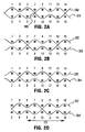
- FIGS. 2A to 2D show the paths in the CD of four successive weft yarn pairs of the embodiment of FIG. 1 ;
- FIG. 3 shows the path in the MD of one stacked pair of warp yarns of the embodiment of FIG. 1 ;
- FIG. 4 is a weave diagram showing one repeat of the weave pattern of the embodiment of FIG. 1 ;
- FIGS. 5A to 5C show respectively the paths of one weft yarn pair of a second, third and fourth embodiment of the invention.
- the fabric of this embodiment is woven to a plain weave design in each of the PS layer 70 and the MS layer 80 , to which each member of each pair of weft yarns, identified by the generic reference numeral 100 , contributes.
- the paths of each member of each pair of weft yarns 100 in each repeat comprise two portions, so that each member alternates between the PS layer 70 and the MS layer 80 , and so that between the first and second portions of the repeat, the first and second members of the pair of weft yarns 100 exchange positions at an exchange point 90 .
- the first member is exposed over a preselected number N 1 of PS warp yarns identified by the generic reference numeral 110 , while the second member is exposed over a preselected number N 2 of MS warp yarns identified by the generic reference numeral 120 .
- the first member is exposed over a preselected number M 1 of MS warp yarns 120 while the second member is exposed over a preselected number M 2 of PS warp yarns 110 .
- FIGS. 2A to 2D the paths in the CD of four successive pairs of weft yarns 100 are shown.
- a first member is shown by a solid line and ascribed an even number 30 , 32 , 34 , and 36
- the second member is shown by a broken line and ascribed an odd number 31 , 33 , 35 and 37 .
- These numbers correspond with the weft yarn numbering indicated at the left side of the weave diagram of FIG. 4 .
- a first set of warp yarns 110 shown as the odd numbered yarns forming the upper layer in FIGS. 1A to 1D
- a second set of warp yarns 120 shown as the even numbered yarns forming the lower layer in FIGS. 1A to 1D , to form vertically stacked pairs.
- These numbers correspond with the warp yarn numbering indicated across the top of the weave diagram of FIG. 4 .
- the two members of each pair of weft yarns 100 follow an identical path, the path of the second member 31 being displaced by one-half of a pattern repeat from the first member 30 .
- the first member 30 in a first portion of the repeat pattern is exposed over two PS warp yarns 1 and 5 , and then switches to the MS layer, passing under PS warp yarn 7 and over MS warp yarn 8 , whence it follows a second portion of the repeat pattern, being exposed over two MS warp yarns 10 and 14 .
- the second member 31 in a first portion of the repeat pattern is exposed over two MS warp yarns 2 and 6 , and then switches to the PS layer, also passing under PS warp yarn 7 and over MS warp yarn 8 , whence it follows a second portion of the repeat pattern, being exposed over two PS warp yarns 9 and 13 .
- a second exchange point 90 occurs between PS warp yarn 15 and MS warp yarn 16 .
- the two members 30 and 31 exchange positions at an exchange point 90 between the vertically stacked pair of warp yarns 7 and 8 .
- the warp path in the MD of the first stacked pair of warp yarns 110 and 120 is shown, the PS warp yarn being shown as yarn 1 and the MS yarn being shown as yarn 2 .
- These yarns, and the weft yarns 100 are identified to correspond with the numbering in the weave diagram of FIG. 4 .
- exchange points 90 are indicated. These occur, for example, for weft yarns 30 and 31 , between warp yarns 7 and 8 , and 15 and 16 . Similarly, exchange points for weft yarns 32 and 33 occur between warp yarns 5 and 6 , and 13 and 14 ; and for weft yarns 34 and 35 between warp yarns 3 and 4 , and 11 and 12 .
- each member of the weft pair identified as 50 A and 51 A, follows an identical path, displaced by one-half of the repeat, and the two members exchange positions in the PS layer 70 and the MS layer 80 at exchange points 90 .
- the weave pattern is a 3/1 broken twill, whereas the weave pattern for the MS surface of the MS layer 80 remains a plain weave.
- each member of the weft pair identified as 50 B and 51 B, follows an identical path, displaced by one-half of the repeat, and the two members exchange positions in the PS layer 70 and the MS layer 80 at exchange points 90 .
- the weave pattern is a 2/1 twill.
- FIG. 5C shows an embodiment similar to that shown in FIG. 5B .
- the weave pattern in both the PS surface of the PS layer 70 and the MS surface of the MS layer 80 is a 2/2 basket weave, and the exchange points occur between two adjacent pairs of stacked warp PS yarns 110 and MS yarns 120 .
- the first exchange point 90 for weft yarns 50 C and 51 C in FIG. 5C occurs below both PS warp yarns 5 and 7 and above both MS warp yarns 6 and 8 .
- the fabrics of this invention have a high projected open area, which after heatsetting is at least 35%, and is preferably between 35% and 50%. These values are necessary to allow sufficient passage of air from the TAD drum through the sheet, particularly where a patterned resin coating is applied to the fabrics.
- the fabrics of this invention have an air permeability, after heatsetting, within the range of 800 to 1200 cubic feet per minute per square foot. More preferably, the fabrics of the invention have an air permeability in the range of 900 to 110 cubic feet per minute per square foot.
- the preferable mesh ranges for the fabrics of this invention are between 35 ⁇ 2 (warp) by 25 ⁇ 2 (weft) and 50 ⁇ 2 (warp) by 40 ⁇ 2 (weft) per inch, so that the mesh ranges, without regard to the stacking of the warp yarns 110 and 120 and the paired weft yarns 100 , are between 70 to 100 for the warp and 50 to 80 for the weft.
- the effective mesh ranges of the fabric are from 35-50 warp/in. and 25-40 weft/in. The effective mesh is that which is seen when determining projected open area.
- the yarns used for both the warps and the wefts in the fabrics of the invention must be resistant to both heat and hydrolytic degradation.
- Suitable materials both for the warp yarns 110 and 120 and for the weft yarns 100 include polyetheretherketone, polyphenylene sulphide, polyethylene terephthalate, and polycyclohexamethalyne terephthalate, acid modified.
- the materials used for the MS warps can be different from the materials used for the PS warps or for the wefts.
- Other polymeric materials such as are commonly used for industrial fabrics, may be appropriate in applications other than for a TAD process.
- suitable yarn sizes for the fabrics of the invention are a minimum of 0.18 mm for the weft yarns 100 , and a minimum of 0.20 mm for the warp yarns 110 and 120 .
- other yarn sizes may be selected depending on the intended use for the fabric.
Abstract
Description
-
- (i) all of the warp yarns are arranged as vertically stacked pairs;
- (ii) all of the weft yarns comprise pairs of intrinsic weft binder yarns each having a first and second member each of which contributes to the structure of both the PS and the MS layers of the fabric and binds together the PS and MS layers; and
- (iii) each pair of intrinsic weft binder yarns forms an unbroken weft path in both the PS layer and the MS layer, whereby when either the first or second member passes from the PS layer to the MS layer, the other member of the pair passes from the MS layer to the PS layer at an exchange point located between at least one common pair of warp yarns.
Claims (8)
Applications Claiming Priority (4)
| Application Number | Priority Date | Filing Date | Title |
|---|---|---|---|
| GB0318220A GB0318220D0 (en) | 2003-08-04 | 2003-08-04 | Triple layer industrial fabric for through-air drying process |
| GB03182201 | 2003-08-04 | ||
| GB0318220.1 | 2003-08-04 | ||
| PCT/CA2004/001446 WO2005012634A2 (en) | 2003-08-04 | 2004-08-04 | Triple layer industrial fabric for through-air drying process |
Publications (2)
| Publication Number | Publication Date |
|---|---|
| US20060211320A1 US20060211320A1 (en) | 2006-09-21 |
| US7682995B2 true US7682995B2 (en) | 2010-03-23 |
Family
ID=27799757
Family Applications (1)
| Application Number | Title | Priority Date | Filing Date |
|---|---|---|---|
| US10/566,938 Expired - Fee Related US7682995B2 (en) | 2003-08-04 | 2004-08-04 | Triple layer industrial fabric for through-air drying process |
Country Status (8)
| Country | Link |
|---|---|
| US (1) | US7682995B2 (en) |
| EP (1) | EP1651810B1 (en) |
| CN (1) | CN1863964A (en) |
| AT (1) | ATE457383T1 (en) |
| CA (1) | CA2534207C (en) |
| DE (1) | DE602004025474D1 (en) |
| GB (1) | GB0318220D0 (en) |
| WO (1) | WO2005012634A2 (en) |
Cited By (1)
| Publication number | Priority date | Publication date | Assignee | Title |
|---|---|---|---|---|
| US11401658B2 (en) | 2017-07-31 | 2022-08-02 | Kimberly-Clark Worldwide, Inc. | Laminated papermaking belt |
Families Citing this family (6)
| Publication number | Priority date | Publication date | Assignee | Title |
|---|---|---|---|---|
| US7426944B2 (en) * | 2004-09-30 | 2008-09-23 | Astenjohnson, Inc. | Double layer forming fabric with high center plane resistance |
| US7357155B2 (en) * | 2005-12-29 | 2008-04-15 | Albany International Corp. | Different contour paired binders in multi-layer fabrics |
| US7896034B2 (en) * | 2009-03-18 | 2011-03-01 | Voith Patent Gmbh | Heat- and corrosion-resistant fabric |
| FI128025B (en) | 2017-03-24 | 2019-08-15 | Valmet Technologies Oy | An industrial textile |
| CN113957589B (en) * | 2021-11-23 | 2023-02-21 | 上海金熊造纸网毯有限公司 | Production process of papermaking felt special for packaging paper |
| CN114457487A (en) * | 2022-01-04 | 2022-05-10 | 深圳全棉时代科技有限公司 | Partition jacquard thermal-insulation gauze |
Citations (11)
| Publication number | Priority date | Publication date | Assignee | Title |
|---|---|---|---|---|
| US4376013A (en) * | 1980-03-14 | 1983-03-08 | The Lindsay Wire Weaving Company | Process for removal of pitch-containing water and method of coating belts for paper machine |
| CA1188556A (en) | 1981-09-15 | 1985-06-11 | William H. Dutt | Dewatering press |
| CA1248799A (en) | 1984-02-23 | 1989-01-17 | Asten, Inc. | Abrasion and hydrolysis resistant joining wire and coil material for fabric seams |
| US4921750A (en) * | 1988-05-25 | 1990-05-01 | Asten Group, Inc. | Papermaker's thru-dryer embossing fabric |
| US5496624A (en) * | 1994-06-02 | 1996-03-05 | The Procter & Gamble Company | Multiple layer papermaking belt providing improved fiber support for cellulosic fibrous structures, and cellulosic fibrous structures produced thereby |
| US5555917A (en) * | 1995-08-11 | 1996-09-17 | Wangner Systems Corporation | Sixteen harness multi-layer forming fabric |
| CA2220653A1 (en) | 1997-01-31 | 1998-07-31 | The Orr Felt Company | Imprinting press section felt for paper pulp, method of imprinting and drying paper pulp, and pulp sheet having machine direction grooves and ridges formed therein with enhanced drying and strength characteristics |
| CA2228297A1 (en) | 1997-09-30 | 1999-03-30 | Asten, Inc. | Woven loop seam fabric with improved loop alignment |
| US6349749B1 (en) * | 1999-07-09 | 2002-02-26 | Geschmay Corp. | Woven fabric |
| CA2390612A1 (en) | 2001-06-21 | 2002-12-21 | Weavexx Corporation | Papermaker's forming fabric |
| EP1311723A1 (en) | 2000-08-16 | 2003-05-21 | Andreas Kufferath GmbH & Co. KG | Composite fabric |
-
2003
- 2003-08-04 GB GB0318220A patent/GB0318220D0/en not_active Ceased
-
2004
- 2004-08-04 EP EP20040761612 patent/EP1651810B1/en not_active Not-in-force
- 2004-08-04 US US10/566,938 patent/US7682995B2/en not_active Expired - Fee Related
- 2004-08-04 AT AT04761612T patent/ATE457383T1/en not_active IP Right Cessation
- 2004-08-04 CA CA002534207A patent/CA2534207C/en not_active Expired - Fee Related
- 2004-08-04 DE DE200460025474 patent/DE602004025474D1/en active Active
- 2004-08-04 CN CNA2004800288757A patent/CN1863964A/en active Pending
- 2004-08-04 WO PCT/CA2004/001446 patent/WO2005012634A2/en active Application Filing
Patent Citations (12)
| Publication number | Priority date | Publication date | Assignee | Title |
|---|---|---|---|---|
| US4376013A (en) * | 1980-03-14 | 1983-03-08 | The Lindsay Wire Weaving Company | Process for removal of pitch-containing water and method of coating belts for paper machine |
| CA1188556A (en) | 1981-09-15 | 1985-06-11 | William H. Dutt | Dewatering press |
| CA1248799A (en) | 1984-02-23 | 1989-01-17 | Asten, Inc. | Abrasion and hydrolysis resistant joining wire and coil material for fabric seams |
| US4921750A (en) * | 1988-05-25 | 1990-05-01 | Asten Group, Inc. | Papermaker's thru-dryer embossing fabric |
| US5496624A (en) * | 1994-06-02 | 1996-03-05 | The Procter & Gamble Company | Multiple layer papermaking belt providing improved fiber support for cellulosic fibrous structures, and cellulosic fibrous structures produced thereby |
| US5555917A (en) * | 1995-08-11 | 1996-09-17 | Wangner Systems Corporation | Sixteen harness multi-layer forming fabric |
| CA2220653A1 (en) | 1997-01-31 | 1998-07-31 | The Orr Felt Company | Imprinting press section felt for paper pulp, method of imprinting and drying paper pulp, and pulp sheet having machine direction grooves and ridges formed therein with enhanced drying and strength characteristics |
| CA2228297A1 (en) | 1997-09-30 | 1999-03-30 | Asten, Inc. | Woven loop seam fabric with improved loop alignment |
| US6349749B1 (en) * | 1999-07-09 | 2002-02-26 | Geschmay Corp. | Woven fabric |
| EP1311723A1 (en) | 2000-08-16 | 2003-05-21 | Andreas Kufferath GmbH & Co. KG | Composite fabric |
| US20030178087A1 (en) | 2000-08-16 | 2003-09-25 | Heinz Odenthal | Composite fabric |
| CA2390612A1 (en) | 2001-06-21 | 2002-12-21 | Weavexx Corporation | Papermaker's forming fabric |
Cited By (1)
| Publication number | Priority date | Publication date | Assignee | Title |
|---|---|---|---|---|
| US11401658B2 (en) | 2017-07-31 | 2022-08-02 | Kimberly-Clark Worldwide, Inc. | Laminated papermaking belt |
Also Published As
| Publication number | Publication date |
|---|---|
| US20060211320A1 (en) | 2006-09-21 |
| ATE457383T1 (en) | 2010-02-15 |
| CA2534207A1 (en) | 2005-02-10 |
| EP1651810A2 (en) | 2006-05-03 |
| EP1651810B1 (en) | 2010-02-10 |
| CA2534207C (en) | 2009-11-17 |
| WO2005012634A2 (en) | 2005-02-10 |
| GB0318220D0 (en) | 2003-09-03 |
| EP1651810A4 (en) | 2006-12-06 |
| CN1863964A (en) | 2006-11-15 |
| DE602004025474D1 (en) | 2010-03-25 |
| WO2005012634A3 (en) | 2005-09-22 |
Similar Documents
| Publication | Publication Date | Title |
|---|---|---|
| JP4961109B2 (en) | Paired warp 3-layer fabric with optimal sheet manufacturing characteristics | |
| AU2005267726C1 (en) | Paired warp triple layer forming fabrics with optimum sheet building characteristics | |
| US5503196A (en) | Papermakers fabric having a system of machine-direction yarns residing interior of the fabric surfaces | |
| AU2003297086B2 (en) | Double cross parallel binder fabric | |
| KR101343811B1 (en) | Multi-layer fabric with paired binder yarns having different contour patterns | |
| CA2599939C (en) | Double layer forming fabric with paired warp binder yarns | |
| US6827821B2 (en) | High permeability, multi-layer woven members employing machine direction binder yarns for use in papermaking machine | |
| JPH10168777A (en) | Permaker's fabric having paired different machinedirection yarn weaving as one | |
| AU2006201298A1 (en) | Stable forming fabric with high fiber support | |
| WO2004048682A1 (en) | High permeability woven members employing paired machine direction yarns for use in papermaking machine | |
| US7682995B2 (en) | Triple layer industrial fabric for through-air drying process | |
| KR101010239B1 (en) | Dryer fabric with air channels | |
| CA2658967C (en) | Dryer fabric |
Legal Events
| Date | Code | Title | Description |
|---|---|---|---|
| AS | Assignment |
Owner name: ASTENJOHNSON, INC., SOUTH CAROLINA Free format text: ASSIGNMENT OF ASSIGNORS INTEREST;ASSIGNORS:STONE, RICHARD;JOHNSON, DALE B.;REEL/FRAME:017540/0769 Effective date: 20060201 Owner name: ASTENJOHNSON, INC.,SOUTH CAROLINA Free format text: ASSIGNMENT OF ASSIGNORS INTEREST;ASSIGNORS:STONE, RICHARD;JOHNSON, DALE B.;REEL/FRAME:017540/0769 Effective date: 20060201 |
|
| AS | Assignment |
Owner name: BANK OF AMERICA, N.A., AS COLLATERAL AGENT, ILLINO Free format text: NOTICE OF GRANT OF SECURITY INTEREST IN PATENTS;ASSIGNOR:ASTENJOHNSON, INC.;REEL/FRAME:020986/0428 Effective date: 20071108 Owner name: BANK OF AMERICA, N.A., AS COLLATERAL AGENT,ILLINOI Free format text: NOTICE OF GRANT OF SECURITY INTEREST IN PATENTS;ASSIGNOR:ASTENJOHNSON, INC.;REEL/FRAME:020986/0428 Effective date: 20071108 |
|
| STCF | Information on status: patent grant |
Free format text: PATENTED CASE |
|
| AS | Assignment |
Owner name: BANK OF AMERICA, N.A., AS COLLATERAL AGENT, ILLINO Free format text: NOTICE OF GRANT OF SECURITY INTEREST IN PATENTS;ASSIGNOR:ASTENJOHNSON, INC.;REEL/FRAME:027531/0067 Effective date: 20120111 |
|
| FPAY | Fee payment |
Year of fee payment: 4 |
|
| AS | Assignment |
Owner name: BANK OF AMERICA, N.A., AS COLLATERAL AGENT, TEXAS Free format text: NOTICE OF GRANT OF SECURITY INTEREST IN PATENTS;ASSIGNOR:ASTENJOHNSON, INC.;REEL/FRAME:039257/0751 Effective date: 20160630 |
|
| MAFP | Maintenance fee payment |
Free format text: PAYMENT OF MAINTENANCE FEE, 8TH YEAR, LARGE ENTITY (ORIGINAL EVENT CODE: M1552) Year of fee payment: 8 |
|
| FEPP | Fee payment procedure |
Free format text: MAINTENANCE FEE REMINDER MAILED (ORIGINAL EVENT CODE: REM.); ENTITY STATUS OF PATENT OWNER: LARGE ENTITY |
|
| LAPS | Lapse for failure to pay maintenance fees |
Free format text: PATENT EXPIRED FOR FAILURE TO PAY MAINTENANCE FEES (ORIGINAL EVENT CODE: EXP.); ENTITY STATUS OF PATENT OWNER: LARGE ENTITY |
|
| STCH | Information on status: patent discontinuation |
Free format text: PATENT EXPIRED DUE TO NONPAYMENT OF MAINTENANCE FEES UNDER 37 CFR 1.362 |
|
| FP | Lapsed due to failure to pay maintenance fee |
Effective date: 20220323 |