US7695703B2 - High temperature catalyst and process for selective catalytic reduction of NOx in exhaust gases of fossil fuel combustion - Google Patents
High temperature catalyst and process for selective catalytic reduction of NOx in exhaust gases of fossil fuel combustion Download PDFInfo
- Publication number
- US7695703B2 US7695703B2 US12/024,416 US2441608A US7695703B2 US 7695703 B2 US7695703 B2 US 7695703B2 US 2441608 A US2441608 A US 2441608A US 7695703 B2 US7695703 B2 US 7695703B2
- Authority
- US
- United States
- Prior art keywords
- slurry
- hours
- iron
- zeolite
- calcining
- Prior art date
- Legal status (The legal status is an assumption and is not a legal conclusion. Google has not performed a legal analysis and makes no representation as to the accuracy of the status listed.)
- Active, expires
Links
Images


Classifications
-
- B—PERFORMING OPERATIONS; TRANSPORTING
- B01—PHYSICAL OR CHEMICAL PROCESSES OR APPARATUS IN GENERAL
- B01D—SEPARATION
- B01D53/00—Separation of gases or vapours; Recovering vapours of volatile solvents from gases; Chemical or biological purification of waste gases, e.g. engine exhaust gases, smoke, fumes, flue gases, aerosols
- B01D53/34—Chemical or biological purification of waste gases
- B01D53/92—Chemical or biological purification of waste gases of engine exhaust gases
- B01D53/94—Chemical or biological purification of waste gases of engine exhaust gases by catalytic processes
- B01D53/9404—Removing only nitrogen compounds
- B01D53/9409—Nitrogen oxides
- B01D53/9413—Processes characterised by a specific catalyst
- B01D53/9418—Processes characterised by a specific catalyst for removing nitrogen oxides by selective catalytic reduction [SCR] using a reducing agent in a lean exhaust gas
-
- B—PERFORMING OPERATIONS; TRANSPORTING
- B01—PHYSICAL OR CHEMICAL PROCESSES OR APPARATUS IN GENERAL
- B01J—CHEMICAL OR PHYSICAL PROCESSES, e.g. CATALYSIS OR COLLOID CHEMISTRY; THEIR RELEVANT APPARATUS
- B01J29/00—Catalysts comprising molecular sieves
- B01J29/04—Catalysts comprising molecular sieves having base-exchange properties, e.g. crystalline zeolites
- B01J29/06—Crystalline aluminosilicate zeolites; Isomorphous compounds thereof
- B01J29/064—Crystalline aluminosilicate zeolites; Isomorphous compounds thereof containing iron group metals, noble metals or copper
- B01J29/072—Iron group metals or copper
-
- B—PERFORMING OPERATIONS; TRANSPORTING
- B01—PHYSICAL OR CHEMICAL PROCESSES OR APPARATUS IN GENERAL
- B01J—CHEMICAL OR PHYSICAL PROCESSES, e.g. CATALYSIS OR COLLOID CHEMISTRY; THEIR RELEVANT APPARATUS
- B01J29/00—Catalysts comprising molecular sieves
- B01J29/04—Catalysts comprising molecular sieves having base-exchange properties, e.g. crystalline zeolites
- B01J29/06—Crystalline aluminosilicate zeolites; Isomorphous compounds thereof
- B01J29/076—Crystalline aluminosilicate zeolites; Isomorphous compounds thereof containing arsenic, antimony, bismuth, vanadium, niobium, tantalum, polonium, chromium, molybdenum, tungsten, manganese, technetium or rhenium
-
- B—PERFORMING OPERATIONS; TRANSPORTING
- B01—PHYSICAL OR CHEMICAL PROCESSES OR APPARATUS IN GENERAL
- B01J—CHEMICAL OR PHYSICAL PROCESSES, e.g. CATALYSIS OR COLLOID CHEMISTRY; THEIR RELEVANT APPARATUS
- B01J29/00—Catalysts comprising molecular sieves
- B01J29/04—Catalysts comprising molecular sieves having base-exchange properties, e.g. crystalline zeolites
- B01J29/06—Crystalline aluminosilicate zeolites; Isomorphous compounds thereof
- B01J29/70—Crystalline aluminosilicate zeolites; Isomorphous compounds thereof of types characterised by their specific structure not provided for in groups B01J29/08 - B01J29/65
- B01J29/72—Crystalline aluminosilicate zeolites; Isomorphous compounds thereof of types characterised by their specific structure not provided for in groups B01J29/08 - B01J29/65 containing iron group metals, noble metals or copper
- B01J29/76—Iron group metals or copper
- B01J29/7615—Zeolite Beta
-
- B—PERFORMING OPERATIONS; TRANSPORTING
- B01—PHYSICAL OR CHEMICAL PROCESSES OR APPARATUS IN GENERAL
- B01J—CHEMICAL OR PHYSICAL PROCESSES, e.g. CATALYSIS OR COLLOID CHEMISTRY; THEIR RELEVANT APPARATUS
- B01J29/00—Catalysts comprising molecular sieves
- B01J29/04—Catalysts comprising molecular sieves having base-exchange properties, e.g. crystalline zeolites
- B01J29/06—Crystalline aluminosilicate zeolites; Isomorphous compounds thereof
- B01J29/70—Crystalline aluminosilicate zeolites; Isomorphous compounds thereof of types characterised by their specific structure not provided for in groups B01J29/08 - B01J29/65
- B01J29/78—Crystalline aluminosilicate zeolites; Isomorphous compounds thereof of types characterised by their specific structure not provided for in groups B01J29/08 - B01J29/65 containing arsenic, antimony, bismuth, vanadium, niobium, tantalum, polonium, chromium, molybdenum, tungsten, manganese, technetium or rhenium
- B01J29/7815—Zeolite Beta
-
- B—PERFORMING OPERATIONS; TRANSPORTING
- B01—PHYSICAL OR CHEMICAL PROCESSES OR APPARATUS IN GENERAL
- B01J—CHEMICAL OR PHYSICAL PROCESSES, e.g. CATALYSIS OR COLLOID CHEMISTRY; THEIR RELEVANT APPARATUS
- B01J37/00—Processes, in general, for preparing catalysts; Processes, in general, for activation of catalysts
- B01J37/02—Impregnation, coating or precipitation
- B01J37/024—Multiple impregnation or coating
- B01J37/0246—Coatings comprising a zeolite
-
- B—PERFORMING OPERATIONS; TRANSPORTING
- B01—PHYSICAL OR CHEMICAL PROCESSES OR APPARATUS IN GENERAL
- B01J—CHEMICAL OR PHYSICAL PROCESSES, e.g. CATALYSIS OR COLLOID CHEMISTRY; THEIR RELEVANT APPARATUS
- B01J37/00—Processes, in general, for preparing catalysts; Processes, in general, for activation of catalysts
- B01J37/02—Impregnation, coating or precipitation
- B01J37/03—Precipitation; Co-precipitation
- B01J37/038—Precipitation; Co-precipitation to form slurries or suspensions, e.g. a washcoat
-
- B—PERFORMING OPERATIONS; TRANSPORTING
- B01—PHYSICAL OR CHEMICAL PROCESSES OR APPARATUS IN GENERAL
- B01J—CHEMICAL OR PHYSICAL PROCESSES, e.g. CATALYSIS OR COLLOID CHEMISTRY; THEIR RELEVANT APPARATUS
- B01J37/00—Processes, in general, for preparing catalysts; Processes, in general, for activation of catalysts
- B01J37/28—Phosphorising
-
- B—PERFORMING OPERATIONS; TRANSPORTING
- B01—PHYSICAL OR CHEMICAL PROCESSES OR APPARATUS IN GENERAL
- B01D—SEPARATION
- B01D2251/00—Reactants
- B01D2251/20—Reductants
- B01D2251/206—Ammonium compounds
- B01D2251/2062—Ammonia
-
- B—PERFORMING OPERATIONS; TRANSPORTING
- B01—PHYSICAL OR CHEMICAL PROCESSES OR APPARATUS IN GENERAL
- B01D—SEPARATION
- B01D2255/00—Catalysts
- B01D2255/20—Metals or compounds thereof
- B01D2255/206—Rare earth metals
-
- B—PERFORMING OPERATIONS; TRANSPORTING
- B01—PHYSICAL OR CHEMICAL PROCESSES OR APPARATUS IN GENERAL
- B01D—SEPARATION
- B01D2255/00—Catalysts
- B01D2255/20—Metals or compounds thereof
- B01D2255/207—Transition metals
- B01D2255/20715—Zirconium
-
- B—PERFORMING OPERATIONS; TRANSPORTING
- B01—PHYSICAL OR CHEMICAL PROCESSES OR APPARATUS IN GENERAL
- B01D—SEPARATION
- B01D2255/00—Catalysts
- B01D2255/20—Metals or compounds thereof
- B01D2255/207—Transition metals
- B01D2255/20738—Iron
-
- B—PERFORMING OPERATIONS; TRANSPORTING
- B01—PHYSICAL OR CHEMICAL PROCESSES OR APPARATUS IN GENERAL
- B01D—SEPARATION
- B01D2255/00—Catalysts
- B01D2255/20—Metals or compounds thereof
- B01D2255/207—Transition metals
- B01D2255/20776—Tungsten
-
- B—PERFORMING OPERATIONS; TRANSPORTING
- B01—PHYSICAL OR CHEMICAL PROCESSES OR APPARATUS IN GENERAL
- B01D—SEPARATION
- B01D2255/00—Catalysts
- B01D2255/50—Zeolites
-
- B—PERFORMING OPERATIONS; TRANSPORTING
- B01—PHYSICAL OR CHEMICAL PROCESSES OR APPARATUS IN GENERAL
- B01D—SEPARATION
- B01D2255/00—Catalysts
- B01D2255/50—Zeolites
- B01D2255/502—Beta zeolites
-
- B—PERFORMING OPERATIONS; TRANSPORTING
- B01—PHYSICAL OR CHEMICAL PROCESSES OR APPARATUS IN GENERAL
- B01D—SEPARATION
- B01D2258/00—Sources of waste gases
- B01D2258/01—Engine exhaust gases
- B01D2258/012—Diesel engines and lean burn gasoline engines
-
- B—PERFORMING OPERATIONS; TRANSPORTING
- B01—PHYSICAL OR CHEMICAL PROCESSES OR APPARATUS IN GENERAL
- B01D—SEPARATION
- B01D2258/00—Sources of waste gases
- B01D2258/01—Engine exhaust gases
- B01D2258/018—Natural gas engines
-
- B—PERFORMING OPERATIONS; TRANSPORTING
- B01—PHYSICAL OR CHEMICAL PROCESSES OR APPARATUS IN GENERAL
- B01J—CHEMICAL OR PHYSICAL PROCESSES, e.g. CATALYSIS OR COLLOID CHEMISTRY; THEIR RELEVANT APPARATUS
- B01J2229/00—Aspects of molecular sieve catalysts not covered by B01J29/00
- B01J2229/10—After treatment, characterised by the effect to be obtained
- B01J2229/18—After treatment, characterised by the effect to be obtained to introduce other elements into or onto the molecular sieve itself
- B01J2229/186—After treatment, characterised by the effect to be obtained to introduce other elements into or onto the molecular sieve itself not in framework positions
-
- B—PERFORMING OPERATIONS; TRANSPORTING
- B01—PHYSICAL OR CHEMICAL PROCESSES OR APPARATUS IN GENERAL
- B01J—CHEMICAL OR PHYSICAL PROCESSES, e.g. CATALYSIS OR COLLOID CHEMISTRY; THEIR RELEVANT APPARATUS
- B01J2229/00—Aspects of molecular sieve catalysts not covered by B01J29/00
- B01J2229/30—After treatment, characterised by the means used
- B01J2229/36—Steaming
-
- B—PERFORMING OPERATIONS; TRANSPORTING
- B01—PHYSICAL OR CHEMICAL PROCESSES OR APPARATUS IN GENERAL
- B01J—CHEMICAL OR PHYSICAL PROCESSES, e.g. CATALYSIS OR COLLOID CHEMISTRY; THEIR RELEVANT APPARATUS
- B01J2229/00—Aspects of molecular sieve catalysts not covered by B01J29/00
- B01J2229/30—After treatment, characterised by the means used
- B01J2229/40—Special temperature treatment, i.e. other than just for template removal
Definitions
- the invention relates to catalysts and processes for the reduction of NO x using a reducing agent such as NH 3 in combustion exhaust at temperatures from 300° C. to over 600° C.
- a reducing agent such as NH 3
- Selective catalytic reduction is a technology for reduction of nitrogen oxide (NO x ) emissions from combined and simple cycle power plants and coal-fired boilers.
- the process involves injecting NH 3 into the exhaust gas upstream of a catalytic reactor. Within the catalyst bed, NO x reacts with adsorbed NH 3 in the presence of O 2 to form primarily N 2 and water.
- Traditional catalysts employed by the process consist of V 2 O 5 supported on high-surface-area TiO 2 . The process achieves up to 90-95% NO x reduction efficiency at low to moderate reaction temperatures (300-420° C.).
- Traditional SCR processes are operated with stoichiometric NH 3 /NO x ratios consistent with an 80-90% NOx reduction.
- NH 3 slip contributes to emissions of nitrogen compound into the atmosphere and leads to the formation of corrosive ammonium sulfates and bisulfates downstream of the SCR. These compounds also may plug heat exchange surfaces in the heat recovery steam generator (HRSG).
- HRSG heat recovery steam generator
- the SCR reactor is integrated into the HRSG.
- the catalyst temperature under normal operation conditions of 50-100% load is between 300 and 370° C.
- the temperature of the exhaust leaving a high efficiency gas turbine can exceed 600° C. Absent any heat exchange surfaces in the post turbine enclosure, the reactions between ammonia and NO x encounter these high temperatures. This requires an SCR catalyst durable to high temperatures and thermal shock, since the temperature in the gas turbine exhaust reaches its maximum in a short period of time, such as 10 minutes.
- High temperature of the exhaust gases requires a reduction in the distance between NH3 injection plane and a face of SCR in order to minimize substantial decomposition of ammonia at temperatures above 500° C.
- a short distance between ammonia injection grid and the face of SCR dictates the installation of special distribution/mixing devices in order to mitigate maldistribution problems resulting from shrinking zone for ammonia and NOx upstream mixing.
- Locating a V 2 O 5 /TiO 2 SCR catalyst downstream of a gas turbine in temperatures above 550° C. is not feasible, as the temperatures of the flue gas will rapidly deactivate the V 2 O 5 /TiO 2 catalyst, due to a transformation of the TiO 2 from the high surface area anatase phase to the low surface area rutile phase.
- zeolites ZSM-5 and zeolite beta appears to be the most promising.
- the zeolite-based catalyst is unable to effectively oxidize NO. Consequently, a metal function, such as iron, cobalt, etc. is added to the acidified zeolite in order to oxidize NO to NO 2 , which is decomposed according to the following reaction scheme (Long and Yang, 2002):
- the rate-limiting step in the reaction sequence is the oxidation of NO to NO 2 .
- ammonia rapidly adsorbs onto the Br ⁇ nsted acidic sites on the surface of the zeolite to yield adsorbed ammonium ions.
- NO is oxidized over the metal function (iron oxide) to yield NO 2 .
- NO 2 interacts with the adsorbed ammonium ions to form an adsorbed ammonium nitrite complex, which decomposes upon reaction with NO to yield N 2 and H 2 O, completing the catalytic cycle.
- the overall reaction is identical to that of conventional V 2 O 5 /TiO 2 SCR catalysts. 4NH3+4NO+O 2 ⁇ 4N 2 +6H 2 O (5)
- Tran et al. (U.S. Pat. Nos. 6,689,709 and 6,914,026) report the use of iron exchanged zeolite beta and iron/cerium exchanged zeolite beta in the selective catalytic reduction of NOx using NH3.
- the catalyst was prepared by ion exchange of zeolite beta using cerium, followed by ion exchange with iron.
- the catalyst achieved enhanced stability over a material prepared without the addition of cerium.
- Tran et al. also report the improved stability achieved upon steam treatment at 650° C., 10% H 2 O for 2 hours. In all cases, catalytic materials lose activity over time.
- Absil et al. (U.S. Pat. No. 5,710,085) report improved durability of zeolite beta upon treatment using phosphorous. The resulting material displayed enhanced stability and activity during catalytic cracking studies. Exposure of zeolite to water vapor at an elevated temperature results in the removal of framework aluminum. However hydrothermal treatments under some conditions are known to enhance both the structural stability and acidity of zeolites (Kerr et al., 1970, Breck 1974, Chen and McCullen, 1988; Stevenson et al., 2002).
- prior catalysts do not provide stability and adequate NOx removal efficiency at temperatures above about 550° C. Thus, they cannot efficiently reduce NOx emissions in a direct gas turbine exhaust, such as in simple cycle power plants, without dilution of the exhaust with cooler air. However, dilution of the exhaust significantly reduces the overall gas turbine efficiency, and is not a cost-effective option.
- FIG. 1 is a schematic diagram of a gas turbine with exhaust cleaned by selective catalytic reduction. Dashed lines are used for some curves to distinguish them from other crossing curves.
- FIG. 2 compares NO reduction efficiency over time for 8 tested examples of the invention and a baseline example without improvements of the invention.
- FIG. 1 illustrates a gas turbine system 20 with an air input 22 , a fuel input 24 , a gas turbine 26 , a combustion exhaust 28 , a reducer (ammonia) input 30 , a selective catalytic reduction bed 32 , and a cleaned exhaust 34 .
- Ammonia is injected through nozzles installed within an ammonia distribution grid that is located a short distance from the face of the SCR bed 32 .
- the short distance between the ammonia injection grid and the face of the SCR is required to minimize the decomposition of ammonia at high temperatures of the exhaust above 550° C.
- a short NH3/NOx mixing zone can lead to a severe maldistribution effect and can significantly reduce the performance of the SCR downstream.
- a baseline catalyst was produced with known methods as described under example 1 below. NO x removal efficiency at 605° C. for the baseline sample is represented by curve E 1 . Eight other catalysts were prepared according to examples 2-9 below. Their NO x removal efficiencies are represented by curves E 2 -E 9 respectively.
- the baseline curve E 1 dives constantly downward, never stabilizing. In contrast, the inventive examples show full or greatly improved stability over time. Ammonia slip was reduced in the inventive samples, as detailed in tables below. Only catalysts prepared with the following three steps in combination, using certain characteristic ranges in the preparation process, showed the best improvement.
- a basic aspect of the invention is preparing a metal-containing zeolite catalytic material by: (1) steam treatment of the zeolite, (2) addition of iron into the pore volume of the steam-treated zeolite, and (3) high-temperature calcinations.
- the order and number of the above steps may vary, as exemplified below.
- high temperature calcination at 750 C-900 C for 1-5 hours was performed at a time after a steam treatment at 500 C-600 C for 5-15 hours.
- the inventors expected that various alternative base metals or platinum group metals could be used for step 2, and that at least some of them would provide similar efficiencies. However, it was found that at least iron is essential for the best stability at high temperatures. Other metals may be added in addition to iron as later described to provide enhancements.
- a zeolite for example zeolite Y, zeolite beta and/or zeolite ZSM-5
- steam e.g. water vapor
- Exposure of zeolites to water vapor at temperatures greater than about 400° C. is known to destabilize zeolites (Breck, 1974), so this step of the invention may seem counter-intuitive.
- Exposure to water vapor results in dealumination (removal of framework aluminum) of the zeolite.
- Dealumination of a zeolite occurs via the following reaction (Breck, 1974):
- the present steam treatment of zeolite may be performed at a temperature between about 400° C. and about 800° C., preferably between 500° C. and 600° C., employing between about 5% and 100% water vapor, preferably between about 10% and 25%, for a duration between 30 minutes and 48 hours, preferably between 2 hours and 24 hours, and more preferably between 5 hours and 15 hours.
- the zeolite is preferably loaded with iron necessary to catalyze the oxidation of NO to NO 2 as described in equation 2.
- Promoters such as tungsten, lanthanum, cerium, barium, vanadium, phosphorous and cesium, may also be added at this time.
- Techniques used in loading metals into zeolite include, but are not limited to, ion exchange, impregnation, and metal vapor deposition. These techniques are known in the art.
- the catalyst may be prepared by performing the metal loading step first followed by steam treatment.
- a portion of the metals and/or certain metals may be incorporated prior to steam treatment, with the remaining metals incorporated following steam treatment.
- the zeolite is stabilized by calcining in dry air (less than 2% H 2 O) at an elevated temperature.
- High temperature calcination is a key step in the preparation of the catalyst disclosed herein.
- the calcination is performed at about 500° C.-1100° C., and preferably between about 750° C. and 900° C.
- the duration of the calcination is between about 30 minutes and about 72 hours, and preferably between about 1 hours and 5 hours.
- This high temperature calcination results in dehydroxylation of the zeolite, i.e., removal of water from the hydroxyl nest. While not wishing to be bound by any theory, it is believed that the high temperature thermal treatment stabilizes the zeolite by closing a “defect” site, thereby reducing the size of the unit cell.
- the catalytic metals, or a portion thereof become incorporated into the defect site, resulting in a highly stabilized metal phase.
- a catalytic metal necessary to oxidize NO to NO 2 (equation 2), especially iron, must be incorporated into the catalyst.
- Metals may be incorporated at several steps during the manufacture of the catalyst. For example, metals providing either oxidation or stabilizing functions may be incorporated prior to steam treatment or following steam treatment, prior to high temperature calcinations. Although less preferred, metals may be incorporated into the zeolite following high temperature calcinations or added to the binder employed in the washcoating of the zeolite. By this last technique, a metal, or a portion thereof, may become incorporated into the lattice of the binder. Examples of binders include aluminum, zirconium, and silicon-based materials as known in the art. Also less preferred, metal may be added to the catalyst following preparation into formed material, such as for example beads, rings, spheres, extrudates, granules, a monolith, or a washcoated monolith.
- Zeolite beta may be synthesized over a range of silica to alumina (SiO 2 /Al 2 O 3 ) ratios between about 10 to greater than 100, and preferably between about 15 and about 25.
- the type and concentration of oxidation metal employed in the catalyst may vary. Examples of oxidation metals for equation 2 include base metals such as iron, cobalt, nickel, chromium and copper, and platinum group metals, examples of which include platinum and palladium. Mixtures thereof may also be employed.
- the metal type and metal loading will be dependent upon the operating temperature of the catalyst. As the operating temperature increases, the decomposition of NH3 over the oxidation metal will become significant, especially as the temperature of the process exceeds about 450° C., and more significant as the temperature of the process exceeds about 550° C.
- the types and concentrations of oxidation metals may vary greatly.
- the loading of base metals may be as low as 0.01%, or as high as about 10%.
- the loading of platinum group metals, known to be more reactive oxidation catalysts, may be as low as 0.001% to as great as 1%.
- the addition of platinum group metals to the catalyst formulation is also expected to facilitate the decomposition of CO and non-methane hydrocarbons.
- Promoters and stabilizing agents may be added to the catalyst to stabilize the structural integrity of the zeolite, stabilize the Br ⁇ nsted acidity of the zeolite, stabilize the oxidation metal, enhance the overall acidity of the zeolite, and/or reduce coke formation within the pores of the zeolite during start-up.
- Such agents may include tungsten, vanadium, lanthanum, cerium, phosphorous, barium, zirconium, and cesium, or mixtures thereof.
- the concentration and type of metal may vary. For example concentrations may be as low as 0.01% or as high as 10%, preferably between 0.3% and 3%. Promoters may also be added to the binder employed in the preparation of the catalyst in order to enhance the hydrothermal stability of the binder material.
- the catalyst described in this invention may be employed in a variety of geometric forms sufficient to bring about contact between the catalyst and the process stream. These forms include beads, rings, spheres, granules, etc.
- the catalyst may be either extruded as a monolith, or may be washcoated onto surfaces of geometric forms, such as for example those listed above.
- the catalyst may be washcoated onto the external surface of a ceramic monolith.
- a monolith may be in a honeycomb form for example, with of a series of straight, non-interconnecting channels.
- washcoat Onto the surface of the monolith, a thin coating of catalytic material is deposited, termed “washcoat” in the art.
- Monoliths offer several advantages, including low thermal mass, excellent utilization of catalytic material, low pressure drop and predictable flow characteristics.
- the SCR process of the invention that uses the catalyst described herein involves contacting the combustion exhaust stream with the catalyst in a manner necessary to facilitate a reaction between NOx (mixtures of NO and NO 2 ) and a reducing agent such as preferably NH 3 .
- the reaction temperature may vary from about 300° C. to over 700° C., preferably 500° C.-650° C., and more preferably 550° C.-620° C.
- the gas hourly space velocity (GHSV) may vary from about 2,000 volumes per hour to over 150,000 per hour, preferably 6,000-50,000 per hour, and even more preferably 15,000-30,000 volumes per hour.
- the concentration of NOx in the process stream may range from less than 10 ppm to greater than several hundred ppm.
- Baseline iron-containing zeolite beta was prepared by adding 15 g of calcined zeolite beta to a 100 ml beaker. To the beaker was added 60 ml of distilled (DI) water, 15 g of zirconium acetate solution (20% ZrO 2 by weight) and 0.109 g iron (III) nitrate nonahydrate (13.8 wt % iron). The resulting solution was mixed to form a slurry containing 0.001 parts iron per part zeolite beta. The slurry was used to washcoat a piece of monolith having a cell density of 230 cells/in 2 and a volume of 21.4 cm 3 . Following washcoating, the monolith was dried, then calcined at 525° C.
- the baseline catalyst described above was evaluated for its ability to decompose NO using NH3.
- the baseline catalyst was evaluated at 605° C. at a space velocity of 20,000 hr ⁇ 1 employing a feed stream consisting of 10% O 2 , 6.8% H 2 O, 50 ppm NO, 60 ppm NH3, balance N 2 .
- the table below reports the conversion of NO and the effluent concentration of NH3 as a function of time.
- the slurry was used to washcoat a piece of monolith having a cell density of 230 cells/in 2 and a volume of 26.2 cm 3 . Following washcoating, the monolith was dried, then calcined at 525° C. for 1 hour.
- the catalyst described above was evaluated for its ability to decompose NO using NH3.
- the catalyst was evaluated at 605° C. at a space velocity of 20,000 hr ⁇ 1 employing a feed stream consisting of 10% O 2 , 6.8% H 2 O, 50 ppm NO, 70 ppm NH3, balance N 2 .
- the table below reports the conversion of NO and the effluent concentration of NH3 as a function of time.
- calcined zeolite beta 25 g was added to a 200 ml beaker. To the beaker was added 50 ml of DI water and the slurry was stirred. To the resulting slurry was added 1.0853 g iron (III) nitrate nonahydrate (13.8 wt % iron). The slurry was then heated to 90° C. Following 3 hours, the slurry was removed and filtered. Resulting material was washed with DI water and filtered again. Dried material was exposed to 15% H 2 O/Air at 525° C. for 5 hours, and then calcined at 825° C. for 2 hours in dry air. Following steam treatment, the material was brown in color. Following high temperature calcinations, the material turned white.
- the resulting material powder was used to prepare a monolithic catalyst.
- 20.0 g of the above zeolite was added to a 100 ml beaker.
- To the beaker was added 65 ml DI water, and 20 g zirconium acetate solution (20% ZrO 2 by weight).
- the resulting solution was mixed to form a slurry.
- the slurry was used to washcoat a piece of monolith having a cell density of 230 cells/in 2 and a volume of 26.2 cm 3 . Following washcoating, the monolith was dried, then calcined at 525° C. for 1 hour.
- the catalyst described above was evaluated for its ability to decompose NO using NH3.
- the catalyst was evaluated at 605° C. at a space velocity of 20,000 hr ⁇ 1 employing a feed stream consisting of 10% O 2 , 6.8% H 2 O, 50 ppm NO, 70 ppm NH3, balance N 2 .
- the table below reports the conversion of NO and the effluent concentration of NH3 as a function of time. Note: Compared to example 1, the zeolite is far more stable. Ammonia slip is less than that of Example 2, indicating a more reactive iron phase.
- the resulting iron-containing zeolite powder was used to prepare a monolithic catalyst. 15.0 g of the above zeolite was added to a 100 ml beaker. To the beaker was added 50 ml DI water, and 15 g zirconium acetate solution. (20% ZrO 2 by weight). The resulting solution was mixed to form a slurry. The slurry was used to washcoat a piece of monolith having a cell density of 230 cells/in 2 and a volume of 26.2 cm 3 . Following washcoating, the monolith was dried, then calcined at 525° C. for 1 hour.
- the catalyst described above was evaluated for its ability to decompose NO using NH3.
- the catalyst was evaluated at 605° C. at a space velocity of 20,000 hr ⁇ 1 employing a feed stream consisting of 10% O 2 , 6.8% H 2 O, 50 ppm NO, 70 ppm NH3, balance N 2 .
- the table below reports the conversion of NO and the effluent concentration of NH3 as a function of time.
- This catalyst was evaluated for its ability to decompose NOx using NH3 employing 60 ppm as well as 70 ppm NH3 in the process stream as described previously.
- the catalyst was evaluated for its ability to decompose NOx employing a 60 ppm inlet NH3 at alternative reaction temperatures employing the process stream described above.
- calcined zeolite beta 50 g was added to a 500 ml beaker. To the beaker was added 400 ml of DI water and the slurry was stirred. To the resulting slurry was added 2.6 g of ammonia metatungstate (94.0 wt % WO 3 ). The slurry was then heated to 90° C. Following 4 hours, the slurry was filtered. Resulting solids were washed with DI water, then dried. Dried tungsten-zeolite was then steam treated by exposure to 15% H 2 O/air at 500° C. for 6 hours, then calcined at 825° C. for 2 hours in dry air.
- the resulting tungsten-containing zeolite powder was used to prepare a monolithic catalyst.
- 15 g of the above zeolite was added to a 100 ml beaker.
- To the beaker was added 80 ml DI water, 0.661 g iron (III) nitrate nonahydrate (13.8 wt % iron), and 15 g zirconium acetate solution (20% ZrO 2 by weight).
- the resulting solution was mixed to form a slurry containing 0.006 parts iron per part zeolite beta.
- the slurry was used to washcoat a piece of monolith having a cell density of 230 cells/in 2 and a volume of 25.9 cm 3 . Following washcoating, the monolith was dried, then calcined at 525° C. for 1 hour.
- the catalyst described above was evaluated for its ability to decompose NO using NH3.
- the catalyst was evaluated at 605° C. at a space velocity of 20,000 hr ⁇ 1 employing a feed stream consisting of 10% O 2 , 6.8% H 2 O, 50 ppm NO, 60 ppm NH3, balance N 2 .
- the table below reports the conversion of NO and the effluent concentration of NH3 as a function of time.
- the catalyst was evaluated for its ability to decompose NOx using NH3 at alternative reaction temperatures employing the process stream described above.
- the catalyst was evaluated for its ability to decompose NOx using NH3 at a space velocity of 15,000 and a temperature of 605° C. employing 60 and 70 ppm NH3 in the process stream as described previously.
- calcined zeolite beta 100 g was added to an 800 ml beaker. To the beaker was added 700 ml of DI water and the slurry was stirred. To the resulting slurry was added 15.5 g of lanthanum nitrate nonahydrate. The slurry was then heated to 95° C. Following 6 hours, the slurry was removed and filtered. Resulting solids were washed with DI water, then dried.
- the resulting iron-lanthanum-containing zeolite powder was used to prepare a monolithic catalyst. 12.25 g of the above zeolite was added to a 100 ml beaker. To the beaker was added 60 ml DI water and 12.25 g zirconium acetate solution (20% ZrO 2 by weight). The resulting solution was mixed to form a slurry. The slurry was used to washcoat a piece of monolith having a cell density of 230 cells/in 2 and a volume of 25.9 cm 3 . Following washcoating, the monolith was dried, then calcined at 525° C. for 1 hour.
- the catalyst described above was evaluated for its ability to decompose NO using NH3.
- the catalyst was evaluated at 605° C. at a space velocity of 20,000 hr ⁇ 1 employing a feed stream consisting of 10% O 2 , 6.8% H 2 O, 50 ppm NO, 70 ppm NH3, balance N 2 .
- the table below reports the conversion of NO and the effluent concentration of NH3 as a function of time.
- lanthanum zeolite beta from Example 6 25 g was added to a 200 ml beaker. To the beaker was added 150 ml of DI water and the slurry was stirred. To the resulting slurry was added 1.81 g of iron (III) nitrate nonahydrate (13.8 wt % iron). The slurry was then heated to 90° C. Following 3 hours, the slurry was removed and filtered. Resulting material was washed with DI water, then dried. Dried material was then steam treated by exposure to 15% H 2 O/Air at 525° C. for 5 hours, then calcined at 825° C. for 2 hours in dry air.
- the resulting iron-lanthanum-containing zeolite powder was used to prepare a monolithic catalyst.
- 15.0 g of the above zeolite was added to a 100 ml beaker.
- To the beaker was added 60 ml DI water and 15.0 g zirconium acetate solution (20% ZrO 2 by weight).
- the resulting solution was mixed to form a slurry.
- the slurry was used to washcoat a piece of monolith having a cell density of 230 cells/in 2 and a volume of 25.9 cm 3 . Following washcoating, the monolith was dried, then calcined at 525° C. for 1 hour.
- the catalyst described above was evaluated for its ability to decompose NO using NH3.
- the catalyst was evaluated at 605° C. at a space velocity of 20,000 hr ⁇ 1 employing a feed stream consisting of 10% O 2 , 6.8% H 2 O, 50 ppm NO, 82 ppm NH3, balance N 2 .
- the table below reports the conversion of NO and the effluent concentration of NH3 as a function of time.
- the catalyst was evaluated for its ability to decompose NOx using NH3 employing 60, 70 and 82 ppm NH3 in the process stream as described previously.
- the resulting iron-tungsten-containing zeolite powder was used to prepare a monolithic catalyst.
- 23.0 g of the above zeolite was added to a 100 ml beaker.
- To the beaker was added 70 ml DI water, and 23 g zirconium acetate solution. (20% ZrO 2 by weight).
- the resulting solution was mixed to form a slurry.
- the slurry was used to washcoat a piece of monolith having a cell density of 230 cells/in 2 and a volume of 26.2 cm 3 . Following washcoating, the monolith was dried, then calcined at 525° C. for 1 hour.
- the catalyst described above was evaluated for its ability to decompose NO using NH3.
- the catalyst was evaluated at 605° C. at a space velocity of 20,000 hr ⁇ 1 employing a feed stream consisting of 10% O 2 , 6.8% H 2 O, 50 ppm NO, 70 ppm NH3, balance N 2 .
- the table below reports the conversion of NO and the effluent concentration of NH3 as a function of time.
- the catalyst was evaluated for its ability to decompose NOx using NH3 at alternative reaction temperatures employing the process stream described above.
- the catalyst was evaluated for its ability to decompose NOx employing a 60 ppm inlet NH3 at alternative reaction temperatures employing the process stream described above.
- the catalyst was then evaluated at a space velocity of 15,000 hr ⁇ 1 employing a process stream described above with a 70 ppm inlet NH3 inlet at a temperature of 605° C.
- the catalyst was then evaluated at a space velocity of 15,000 hr ⁇ 1 employing a process stream described above with a 60 ppm inlet NH3 inlet at a temperature of 605° C.
- the resulting iron-phosphorous-containing zeolite powder was used to prepare a monolithic catalyst. 22.44 g of the above zeolite was added to a 100 ml beaker. To the beaker was added 70 ml DI water, and 22.44 g zirconium acetate solution. (20% ZrO 2 by weight). The resulting solution was mixed to form a slurry. The slurry was used to washcoat a piece of monolith having a cell density of 230 cells/in 2 and a volume of 25.9 cm 3 . Following washcoating, the monolith was dried, then calcined at 525° C. for 1 hour.
- the catalyst described above was evaluated for its ability to decompose NO using NH3.
- the catalyst was evaluated at 605° C. at a space velocity of 20,000 hr ⁇ 1 employing a feed stream consisting of 10% O 2 , 6.8% H 2 O, 50 ppm NO, 70 ppm NH3, balance N 2 .
- the table below reports the conversion of NO and the effluent concentration of NH3 as a function of time.
Abstract
Description
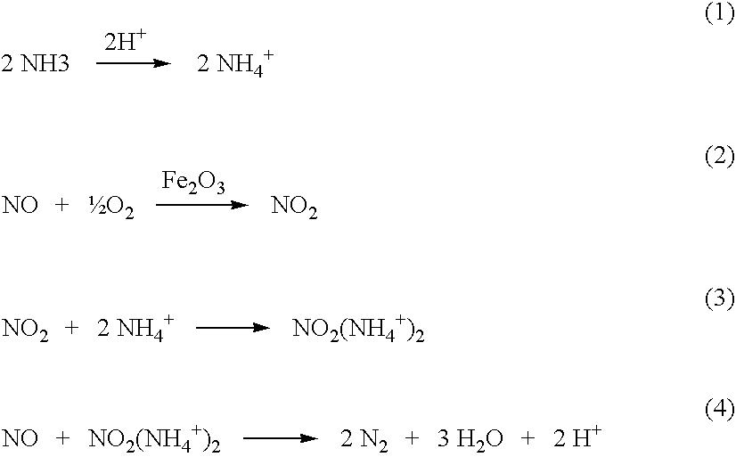
4NH3+4NO+O2→4N2+6H2O (5)


Further, it is believed that by incorporating metals within the zeolite prior to high temperature calcination, the catalytic metals, or a portion thereof, become incorporated into the defect site, resulting in a highly stabilized metal phase.
| Time-on-stream | NO Conversion | Effluent [NH3] |
| 2 hrs | 93.4% | 2.1 ppm |
| 10 hrs | 90.2% | 5.2 ppm |
| 50 hrs | 79.0% | 13.1 |
| 100 hrs | 71.7% | 17.1 ppm |
| Time-on-stream | NO Conversion | Effluent [NH3] |
| 5 hrs | 84.7% | 5.4 ppm |
| 25 hrs | 84.1% | 7.5 ppm |
| 50 hrs | 83.7% | 8.6 ppm |
| Time-on-stream | NO Conversion | Effluent [NH3] |
| 5 hrs | 83.6% | 3.2 ppm |
| 25 hrs | 82.8% | 4.4 ppm |
| 50 hrs | 82.1% | 4.7 ppm |
| Time-on-stream | NO Conversion | Effluent [NH3] |
| 5 hrs | 82.5% | 3.2 ppm |
| 25 hrs | 82.4% | 4.6 ppm |
| 50 hrs | 82.3% | 5.6 |
| 100 hrs | 82.1% | 5.8 ppm |
| [NH3] | NO Conversion | Effluent [NH3] |
| 60 ppm | 76.8% | 3.2 |
| 70 ppm | 82.1% | 5.8 ppm |
| Temperature | NO Conversion | Effluent [NH3] |
| 548° C. | 87.8% | 6.5 ppm |
| 575° C. | 83.5% | 4.8 ppm |
| 590° C. | 80.6% | 4.0 ppm |
| 605° C. | 76.8% | 3.2 ppm |
| Time-on-stream | NO Conversion | Effluent [NH3] |
| 2 hrs | 79.0% | 4.6 ppm |
| 10 hrs | 75.8% | 5.4 ppm |
| 50 hrs | 74.6% | 6.1 ppm |
| Temperature | NO Conversion | Effluent [NH3] |
| 550° C. | 84.7% | 7.7 ppm |
| 580° C. | 80.7% | 7.1 ppm |
| 605° C. | 74.6% | 6.1 ppm |
| [NH3] | NO Conversion | Effluent [NH3] |
| 60 ppm | 77.6% | 3.9 |
| 70 ppm | 86.8% | 6.6 ppm |
| Time-on-stream | NO Conversion | Effluent [NH3] |
| 25 hrs | 87.0% | 4.3 ppm |
| 50 hrs | 86.1% | 5.1 |
| 100 hrs | 84.6% | 5.6 ppm |
| Time-on-stream | NO Conversion | Effluent [NH3] |
| 2 hrs | 89.1% | 3.4 |
| 20 hrs | 89.0% | 5.3 ppm |
| [NH3] | NO Conversion | Effluent [NH3] |
| 60 ppm | 73.2% | 2.1 |
| 70 ppm | 83.2% | 2.1 ppm |
| 82 ppm | 89.0% | 5.3 ppm |
| Time-on-stream | NO Conversion | Effluent [NH3] |
| 5 hrs | 85.4% | 7.4 ppm |
| 25 hrs | 85.8% | 8.5 ppm |
| 50 hrs | 85.9% | 9.0 |
| 100 hrs | 85.5% | 9.1 ppm |
| 150 hrs | 85.5% | 9.1 |
| 200 hrs | 85.5% | 9.1 ppm |
| Temperature | NO Conversion | Effluent [NH3] |
| 545° C. | 92.0% | 15.7 ppm |
| 570° C. | 90.1% | 12.8 ppm |
| 585° C. | 88.1% | 10.7 ppm |
| 605° C. | 85.5% | 9.1 ppm |
| Temperature | NO Conversion | Effluent [NH3] |
| 545° C. | 88.8% | 8.8 ppm |
| 570° C. | 86.2% | 7.1 ppm |
| 585° C. | 83.5% | 6.1 ppm |
| 605° C. | 79.6% | 5.0 ppm |
| GHSV | NO Conversion | Effluent [NH3] |
| 15,000 | 88.4% | 5.5 ppm |
| GHSV | NO Conversion | Effluent [NH3] |
| 15,000 | 84.2% | 3.1 ppm |
| Time-on-stream | NO Conversion | Effluent [NH3] |
| 5 hrs | 90.4% | 1.7 ppm |
| 25 hrs | 89.9% | 2.8 ppm |
| 50 hrs | 88.5% | 3.6 |
| 100 hrs | 86.7% | 5.3 ppm |
Claims (19)
Priority Applications (5)
| Application Number | Priority Date | Filing Date | Title |
|---|---|---|---|
| US12/024,416 US7695703B2 (en) | 2008-02-01 | 2008-02-01 | High temperature catalyst and process for selective catalytic reduction of NOx in exhaust gases of fossil fuel combustion |
| EP08872147A EP2249949A2 (en) | 2008-02-01 | 2008-12-17 | High temperature catalyst and process for selective catalytic reduction of nox in exhaust gases of fossil fuel combustion |
| JP2010544936A JP5404649B2 (en) | 2008-02-01 | 2008-12-17 | Selective catalytic reduction process of NOx in flue gas stream |
| PCT/US2008/013812 WO2009099426A2 (en) | 2008-02-01 | 2008-12-17 | High temperature catalyst and process for selective catalytic reduction of nox in exhaust gases of fossil fuel combustion |
| CN2008801256906A CN101925394A (en) | 2008-02-01 | 2008-12-17 | High temperature catalyst and process for selective catalytic reduction of NOx in exhaust gases of fossil fuel combustion |
Applications Claiming Priority (1)
| Application Number | Priority Date | Filing Date | Title |
|---|---|---|---|
| US12/024,416 US7695703B2 (en) | 2008-02-01 | 2008-02-01 | High temperature catalyst and process for selective catalytic reduction of NOx in exhaust gases of fossil fuel combustion |
Publications (2)
| Publication Number | Publication Date |
|---|---|
| US20090196813A1 US20090196813A1 (en) | 2009-08-06 |
| US7695703B2 true US7695703B2 (en) | 2010-04-13 |
Family
ID=40589614
Family Applications (1)
| Application Number | Title | Priority Date | Filing Date |
|---|---|---|---|
| US12/024,416 Active 2028-06-04 US7695703B2 (en) | 2008-02-01 | 2008-02-01 | High temperature catalyst and process for selective catalytic reduction of NOx in exhaust gases of fossil fuel combustion |
Country Status (5)
| Country | Link |
|---|---|
| US (1) | US7695703B2 (en) |
| EP (1) | EP2249949A2 (en) |
| JP (1) | JP5404649B2 (en) |
| CN (1) | CN101925394A (en) |
| WO (1) | WO2009099426A2 (en) |
Cited By (67)
| Publication number | Priority date | Publication date | Assignee | Title |
|---|---|---|---|---|
| US20120087851A1 (en) * | 2010-10-12 | 2012-04-12 | Basf Se | P/s-tm-comprising zeolites for decomposition of n2o |
| US8734545B2 (en) | 2008-03-28 | 2014-05-27 | Exxonmobil Upstream Research Company | Low emission power generation and hydrocarbon recovery systems and methods |
| US8790609B1 (en) | 2013-06-27 | 2014-07-29 | Siemens Energy, Inc. | Method of yellow plume elimination in gas turbine exhaust |
| US8984857B2 (en) | 2008-03-28 | 2015-03-24 | Exxonmobil Upstream Research Company | Low emission power generation and hydrocarbon recovery systems and methods |
| US9027321B2 (en) | 2008-03-28 | 2015-05-12 | Exxonmobil Upstream Research Company | Low emission power generation and hydrocarbon recovery systems and methods |
| US9101877B2 (en) | 2012-02-13 | 2015-08-11 | Siemens Energy, Inc. | Selective catalytic reduction system and process for control of NOx emissions in a sulfur-containing gas stream |
| US9222671B2 (en) | 2008-10-14 | 2015-12-29 | Exxonmobil Upstream Research Company | Methods and systems for controlling the products of combustion |
| US9353682B2 (en) | 2012-04-12 | 2016-05-31 | General Electric Company | Methods, systems and apparatus relating to combustion turbine power plants with exhaust gas recirculation |
| US9463417B2 (en) | 2011-03-22 | 2016-10-11 | Exxonmobil Upstream Research Company | Low emission power generation systems and methods incorporating carbon dioxide separation |
| US9512759B2 (en) | 2013-02-06 | 2016-12-06 | General Electric Company | System and method for catalyst heat utilization for gas turbine with exhaust gas recirculation |
| US9574496B2 (en) | 2012-12-28 | 2017-02-21 | General Electric Company | System and method for a turbine combustor |
| US9581081B2 (en) | 2013-01-13 | 2017-02-28 | General Electric Company | System and method for protecting components in a gas turbine engine with exhaust gas recirculation |
| US9587510B2 (en) | 2013-07-30 | 2017-03-07 | General Electric Company | System and method for a gas turbine engine sensor |
| US9599021B2 (en) | 2011-03-22 | 2017-03-21 | Exxonmobil Upstream Research Company | Systems and methods for controlling stoichiometric combustion in low emission turbine systems |
| US9599070B2 (en) | 2012-11-02 | 2017-03-21 | General Electric Company | System and method for oxidant compression in a stoichiometric exhaust gas recirculation gas turbine system |
| US9611756B2 (en) | 2012-11-02 | 2017-04-04 | General Electric Company | System and method for protecting components in a gas turbine engine with exhaust gas recirculation |
| US9618261B2 (en) | 2013-03-08 | 2017-04-11 | Exxonmobil Upstream Research Company | Power generation and LNG production |
| US9617914B2 (en) | 2013-06-28 | 2017-04-11 | General Electric Company | Systems and methods for monitoring gas turbine systems having exhaust gas recirculation |
| US9631815B2 (en) | 2012-12-28 | 2017-04-25 | General Electric Company | System and method for a turbine combustor |
| US9631542B2 (en) | 2013-06-28 | 2017-04-25 | General Electric Company | System and method for exhausting combustion gases from gas turbine engines |
| US9670841B2 (en) | 2011-03-22 | 2017-06-06 | Exxonmobil Upstream Research Company | Methods of varying low emission turbine gas recycle circuits and systems and apparatus related thereto |
| US9689309B2 (en) | 2011-03-22 | 2017-06-27 | Exxonmobil Upstream Research Company | Systems and methods for carbon dioxide capture in low emission combined turbine systems |
| US9708977B2 (en) | 2012-12-28 | 2017-07-18 | General Electric Company | System and method for reheat in gas turbine with exhaust gas recirculation |
| US9732675B2 (en) | 2010-07-02 | 2017-08-15 | Exxonmobil Upstream Research Company | Low emission power generation systems and methods |
| US9732673B2 (en) | 2010-07-02 | 2017-08-15 | Exxonmobil Upstream Research Company | Stoichiometric combustion with exhaust gas recirculation and direct contact cooler |
| US9752458B2 (en) | 2013-12-04 | 2017-09-05 | General Electric Company | System and method for a gas turbine engine |
| US9784185B2 (en) | 2012-04-26 | 2017-10-10 | General Electric Company | System and method for cooling a gas turbine with an exhaust gas provided by the gas turbine |
| US9784140B2 (en) | 2013-03-08 | 2017-10-10 | Exxonmobil Upstream Research Company | Processing exhaust for use in enhanced oil recovery |
| US9784182B2 (en) | 2013-03-08 | 2017-10-10 | Exxonmobil Upstream Research Company | Power generation and methane recovery from methane hydrates |
| US9803865B2 (en) | 2012-12-28 | 2017-10-31 | General Electric Company | System and method for a turbine combustor |
| US9810050B2 (en) | 2011-12-20 | 2017-11-07 | Exxonmobil Upstream Research Company | Enhanced coal-bed methane production |
| US9819292B2 (en) | 2014-12-31 | 2017-11-14 | General Electric Company | Systems and methods to respond to grid overfrequency events for a stoichiometric exhaust recirculation gas turbine |
| US9835089B2 (en) | 2013-06-28 | 2017-12-05 | General Electric Company | System and method for a fuel nozzle |
| US9863267B2 (en) | 2014-01-21 | 2018-01-09 | General Electric Company | System and method of control for a gas turbine engine |
| US9869279B2 (en) | 2012-11-02 | 2018-01-16 | General Electric Company | System and method for a multi-wall turbine combustor |
| US9869247B2 (en) | 2014-12-31 | 2018-01-16 | General Electric Company | Systems and methods of estimating a combustion equivalence ratio in a gas turbine with exhaust gas recirculation |
| US9885290B2 (en) | 2014-06-30 | 2018-02-06 | General Electric Company | Erosion suppression system and method in an exhaust gas recirculation gas turbine system |
| US9903271B2 (en) | 2010-07-02 | 2018-02-27 | Exxonmobil Upstream Research Company | Low emission triple-cycle power generation and CO2 separation systems and methods |
| US9903588B2 (en) | 2013-07-30 | 2018-02-27 | General Electric Company | System and method for barrier in passage of combustor of gas turbine engine with exhaust gas recirculation |
| US9903316B2 (en) | 2010-07-02 | 2018-02-27 | Exxonmobil Upstream Research Company | Stoichiometric combustion of enriched air with exhaust gas recirculation |
| US9915200B2 (en) | 2014-01-21 | 2018-03-13 | General Electric Company | System and method for controlling the combustion process in a gas turbine operating with exhaust gas recirculation |
| US9932874B2 (en) | 2013-02-21 | 2018-04-03 | Exxonmobil Upstream Research Company | Reducing oxygen in a gas turbine exhaust |
| US9938861B2 (en) | 2013-02-21 | 2018-04-10 | Exxonmobil Upstream Research Company | Fuel combusting method |
| US9951658B2 (en) | 2013-07-31 | 2018-04-24 | General Electric Company | System and method for an oxidant heating system |
| US10012151B2 (en) | 2013-06-28 | 2018-07-03 | General Electric Company | Systems and methods for controlling exhaust gas flow in exhaust gas recirculation gas turbine systems |
| US10030588B2 (en) | 2013-12-04 | 2018-07-24 | General Electric Company | Gas turbine combustor diagnostic system and method |
| US10047633B2 (en) | 2014-05-16 | 2018-08-14 | General Electric Company | Bearing housing |
| US10060359B2 (en) | 2014-06-30 | 2018-08-28 | General Electric Company | Method and system for combustion control for gas turbine system with exhaust gas recirculation |
| US10079564B2 (en) | 2014-01-27 | 2018-09-18 | General Electric Company | System and method for a stoichiometric exhaust gas recirculation gas turbine system |
| US10094566B2 (en) | 2015-02-04 | 2018-10-09 | General Electric Company | Systems and methods for high volumetric oxidant flow in gas turbine engine with exhaust gas recirculation |
| US10100741B2 (en) | 2012-11-02 | 2018-10-16 | General Electric Company | System and method for diffusion combustion with oxidant-diluent mixing in a stoichiometric exhaust gas recirculation gas turbine system |
| US10107495B2 (en) | 2012-11-02 | 2018-10-23 | General Electric Company | Gas turbine combustor control system for stoichiometric combustion in the presence of a diluent |
| US10145269B2 (en) | 2015-03-04 | 2018-12-04 | General Electric Company | System and method for cooling discharge flow |
| US10208677B2 (en) | 2012-12-31 | 2019-02-19 | General Electric Company | Gas turbine load control system |
| US10215412B2 (en) | 2012-11-02 | 2019-02-26 | General Electric Company | System and method for load control with diffusion combustion in a stoichiometric exhaust gas recirculation gas turbine system |
| US10221762B2 (en) | 2013-02-28 | 2019-03-05 | General Electric Company | System and method for a turbine combustor |
| US10227920B2 (en) | 2014-01-15 | 2019-03-12 | General Electric Company | Gas turbine oxidant separation system |
| US10253690B2 (en) | 2015-02-04 | 2019-04-09 | General Electric Company | Turbine system with exhaust gas recirculation, separation and extraction |
| US10267270B2 (en) | 2015-02-06 | 2019-04-23 | General Electric Company | Systems and methods for carbon black production with a gas turbine engine having exhaust gas recirculation |
| US10273880B2 (en) | 2012-04-26 | 2019-04-30 | General Electric Company | System and method of recirculating exhaust gas for use in a plurality of flow paths in a gas turbine engine |
| US10316746B2 (en) | 2015-02-04 | 2019-06-11 | General Electric Company | Turbine system with exhaust gas recirculation, separation and extraction |
| US10315150B2 (en) | 2013-03-08 | 2019-06-11 | Exxonmobil Upstream Research Company | Carbon dioxide recovery |
| US10434502B2 (en) | 2017-01-13 | 2019-10-08 | Mitsui Mining & Smelting Co., Ltd. | Exhaust gas-purifying composition |
| US10480792B2 (en) | 2015-03-06 | 2019-11-19 | General Electric Company | Fuel staging in a gas turbine engine |
| US10655542B2 (en) | 2014-06-30 | 2020-05-19 | General Electric Company | Method and system for startup of gas turbine system drive trains with exhaust gas recirculation |
| US10688480B2 (en) | 2017-01-13 | 2020-06-23 | Mitsui Mining & Smelting Co., Ltd. | Exhaust gas-purifying composition |
| US10788212B2 (en) | 2015-01-12 | 2020-09-29 | General Electric Company | System and method for an oxidant passageway in a gas turbine system with exhaust gas recirculation |
Families Citing this family (14)
| Publication number | Priority date | Publication date | Assignee | Title |
|---|---|---|---|---|
| US8703636B2 (en) * | 2009-02-27 | 2014-04-22 | Corning Incorporated | Method of manufacturing a catalyst body by post-impregnation |
| US9138685B2 (en) | 2009-08-27 | 2015-09-22 | Tosoh Corporation | Highly hydrothermal-resistant SCR catalyst and manufacturing method therefor |
| GB2477630B (en) | 2010-02-01 | 2014-11-12 | Johnson Matthey Plc | Filter comprising combined soot oxidation and nh3-scr catalyst |
| DE102010022775A1 (en) | 2010-06-04 | 2011-12-08 | Uhde Gmbh | Method and apparatus for removing NOx and N2O |
| NZ608905A (en) * | 2010-10-01 | 2014-07-25 | Beaulieu Group Llc | Lightweight carpet products and method of manufacture thereof |
| CN103153439A (en) * | 2010-10-12 | 2013-06-12 | 巴斯夫欧洲公司 | P/S-TM-comprising zeolites for decomposition of N2O |
| JP5625735B2 (en) * | 2010-10-22 | 2014-11-19 | 東ソー株式会社 | High heat resistant water SCR catalyst and method for producing the same |
| US20120134916A1 (en) * | 2011-02-28 | 2012-05-31 | Fedeyko Joseph M | High-temperature scr catalyst |
| RU2637510C2 (en) | 2011-08-03 | 2017-12-05 | Джонсон Мэтти Плс | Extruded honeycomb catalyst |
| JP5970927B2 (en) * | 2012-04-05 | 2016-08-17 | いすゞ自動車株式会社 | Method for producing urea SCR catalyst |
| WO2018095882A1 (en) * | 2016-11-22 | 2018-05-31 | Umicore Ag & Co. Kg | Iron containing catalyst |
| JP6339306B1 (en) * | 2017-01-13 | 2018-06-06 | 三井金属鉱業株式会社 | Exhaust gas purification composition |
| JP6345372B1 (en) * | 2017-01-13 | 2018-06-20 | 三井金属鉱業株式会社 | Exhaust gas purification composition |
| CN109289905A (en) * | 2018-03-14 | 2019-02-01 | 北京工大环能科技有限公司 | A kind of process for synthetic catalyst for high temperature SCR denitration process |
Citations (12)
| Publication number | Priority date | Publication date | Assignee | Title |
|---|---|---|---|---|
| US3493519A (en) | 1966-03-30 | 1970-02-03 | Mobil Oil Corp | Hydrothermally stable catalysts of high activity and methods for their preparation |
| US4789656A (en) | 1986-03-03 | 1988-12-06 | Mobil Oil Corporation | Crystalline silicate zeolite beta of improved stability |
| EP0384186A1 (en) | 1989-02-07 | 1990-08-29 | Research Association For Residual Oil Processing | Novel iron-containing aluminosilicate |
| WO1996001689A1 (en) | 1994-07-07 | 1996-01-25 | Mobil Oil Corporation | Catalytic system for the reduction of nitrogen oxides |
| US5589147A (en) | 1994-07-07 | 1996-12-31 | Mobil Oil Corporation | Catalytic system for the reducton of nitrogen oxides |
| US5710085A (en) | 1993-11-29 | 1998-01-20 | Mobil Oil Corporation | Manufacture of improved zeolite beta catalyst |
| US20030050182A1 (en) | 2001-09-07 | 2003-03-13 | Engelhard Corporation | Hydrothermally stable metal promoted zeolite beta for NOx reduction |
| US6689709B1 (en) | 2000-11-15 | 2004-02-10 | Engelhard Corporation | Hydrothermally stable metal promoted zeolite beta for NOx reduction |
| US20060088469A1 (en) * | 2002-11-25 | 2006-04-27 | Yara International Asa | Method for preparation and activation of multimetallic zeolite catalysts, a catalyst composition and application for n2o abatement |
| US20070134146A1 (en) * | 2005-12-14 | 2007-06-14 | Ivor Bull | Zeolite catalyst with improved NOX reduction in SCR |
| EP1810751A1 (en) | 2006-01-20 | 2007-07-25 | Universität Karlsruhe (TH) | Method for preparing an iron-containing SCR-catalyst |
| US20080044331A1 (en) * | 2001-03-13 | 2008-02-21 | Uhde Gmbh | Method for Reducing the Content of N2O and NOx in Gases |
Family Cites Families (2)
| Publication number | Priority date | Publication date | Assignee | Title |
|---|---|---|---|---|
| JPS59121115A (en) * | 1982-12-28 | 1984-07-13 | Idemitsu Kosan Co Ltd | Novel faujasite-type crystalline aluminosilicate containing iron |
| JP3298914B2 (en) * | 1991-11-18 | 2002-07-08 | 触媒化成工業株式会社 | Catalyst for reducing nitrogen oxides and method for catalytic reduction and decomposition of nitrogen oxides |
-
2008
- 2008-02-01 US US12/024,416 patent/US7695703B2/en active Active
- 2008-12-17 CN CN2008801256906A patent/CN101925394A/en active Pending
- 2008-12-17 JP JP2010544936A patent/JP5404649B2/en not_active Expired - Fee Related
- 2008-12-17 EP EP08872147A patent/EP2249949A2/en not_active Withdrawn
- 2008-12-17 WO PCT/US2008/013812 patent/WO2009099426A2/en active Application Filing
Patent Citations (14)
| Publication number | Priority date | Publication date | Assignee | Title |
|---|---|---|---|---|
| US3493519A (en) | 1966-03-30 | 1970-02-03 | Mobil Oil Corp | Hydrothermally stable catalysts of high activity and methods for their preparation |
| US4789656A (en) | 1986-03-03 | 1988-12-06 | Mobil Oil Corporation | Crystalline silicate zeolite beta of improved stability |
| EP0384186A1 (en) | 1989-02-07 | 1990-08-29 | Research Association For Residual Oil Processing | Novel iron-containing aluminosilicate |
| US5710085A (en) | 1993-11-29 | 1998-01-20 | Mobil Oil Corporation | Manufacture of improved zeolite beta catalyst |
| WO1996001689A1 (en) | 1994-07-07 | 1996-01-25 | Mobil Oil Corporation | Catalytic system for the reduction of nitrogen oxides |
| US5589147A (en) | 1994-07-07 | 1996-12-31 | Mobil Oil Corporation | Catalytic system for the reducton of nitrogen oxides |
| US6689709B1 (en) | 2000-11-15 | 2004-02-10 | Engelhard Corporation | Hydrothermally stable metal promoted zeolite beta for NOx reduction |
| US20080044331A1 (en) * | 2001-03-13 | 2008-02-21 | Uhde Gmbh | Method for Reducing the Content of N2O and NOx in Gases |
| US20030050182A1 (en) | 2001-09-07 | 2003-03-13 | Engelhard Corporation | Hydrothermally stable metal promoted zeolite beta for NOx reduction |
| US7182927B2 (en) * | 2001-09-07 | 2007-02-27 | Engelhard Corporation | Hydrothermally stable metal promoted zeolite beta for NOx reduction |
| US6914026B2 (en) | 2001-09-07 | 2005-07-05 | Engelhard Corporation | Hydrothermally stable metal promoted zeolite beta for NOx reduction |
| US20060088469A1 (en) * | 2002-11-25 | 2006-04-27 | Yara International Asa | Method for preparation and activation of multimetallic zeolite catalysts, a catalyst composition and application for n2o abatement |
| US20070134146A1 (en) * | 2005-12-14 | 2007-06-14 | Ivor Bull | Zeolite catalyst with improved NOX reduction in SCR |
| EP1810751A1 (en) | 2006-01-20 | 2007-07-25 | Universität Karlsruhe (TH) | Method for preparing an iron-containing SCR-catalyst |
Non-Patent Citations (8)
| Title |
|---|
| Chi-Cheng Liu, Hsisheng Teng; "Cu/MCM-41 for selective catalytic NO reduction with NH3-comparison of different Cu-loading methods"; Applied Catalysis B: Environmental 58; Jan. 4, 2005; pp. 69-77; Elsevier B.V. |
| Gerard Delahay, Stephane Kieger, Nathalie Tanchoux, Philippe Trens, Bernard Coq; "Kinetics of the selective catalytic reduction of NO by NH3 on a Cu-faujasite catalyst"; Applied Catalysts B: Enviromental 52; Jun. 2, 2004; pp. 251-257; Elsevier B.V. |
| Gongshin Qi, Ralph T. Yang; "Ultra-active Fe/ZSM-5 catalyst for selective catalytic reduction of nitric oxide with ammonia" ; Applied Catalysis B: Environmental 60; Mar. 16, 2005; pp. 13-22; Elsevier B.V. |
| Kevin J. Rogers; "SCR Inlet Maldistributions-Their Effects & Strategies for Their Control"; Proceedings of the 2002 Conference on Selective Catalytic Reduction and Selective Non-Catalytic Reduction for NOx Control; Presented in the US; May 15-16, 2002; Published by the National Energy Technology Laboratory. |
| R.Q. Long and R.T. Yang; "Selective Catalytic Reduction of NO with Ammonia over Fe3+-Exchanged Mordenite (Fe-MOR): Catalytic Performance, Characterization, and Mechanistic Study"; Journal of Catalysis 207; 2002; pp. 274-285; Elsevier Science, USA. |
| Ramon Moreno-Tost, Jose Santamaria-Gonzalez, Enrique Rodriguez-Castellon, Antonio Jimenez-Lopez, Miguel A. Autie, Edel Gonzalez, Marisol Carreras Glacial, Carlos De Las Pozas; "Selective catalytic reduction of nitric oxide by ammonia over Cu-exchanged Cuban natural zeolites"; Applied Catalysis B: Environmental 50; Apr. 2, 2004; pp. 279-288; Elsevier B.V. |
| Scott A. Stevenson, Jim C. Vartuli, and Sanjay B. Sharma; "The Effects of Steaming and Sodium Exchange on the Selective Catalytic Reduction of NO and NO2 by NH3 over HZSM-5"; Journal of Catalysis 208; 2002; pp. 106-113; Elsevier Science, USA. |
| V.I. Parvulescu, P. Grange, B. Delmon; "Catalytic removal of NO"; Catalysis Today 46; 1998; pp. 233-316; Elsevier Science B.V. |
Cited By (79)
| Publication number | Priority date | Publication date | Assignee | Title |
|---|---|---|---|---|
| US8734545B2 (en) | 2008-03-28 | 2014-05-27 | Exxonmobil Upstream Research Company | Low emission power generation and hydrocarbon recovery systems and methods |
| US8984857B2 (en) | 2008-03-28 | 2015-03-24 | Exxonmobil Upstream Research Company | Low emission power generation and hydrocarbon recovery systems and methods |
| US9027321B2 (en) | 2008-03-28 | 2015-05-12 | Exxonmobil Upstream Research Company | Low emission power generation and hydrocarbon recovery systems and methods |
| US9222671B2 (en) | 2008-10-14 | 2015-12-29 | Exxonmobil Upstream Research Company | Methods and systems for controlling the products of combustion |
| US9719682B2 (en) | 2008-10-14 | 2017-08-01 | Exxonmobil Upstream Research Company | Methods and systems for controlling the products of combustion |
| US10495306B2 (en) | 2008-10-14 | 2019-12-03 | Exxonmobil Upstream Research Company | Methods and systems for controlling the products of combustion |
| US9732673B2 (en) | 2010-07-02 | 2017-08-15 | Exxonmobil Upstream Research Company | Stoichiometric combustion with exhaust gas recirculation and direct contact cooler |
| US9903271B2 (en) | 2010-07-02 | 2018-02-27 | Exxonmobil Upstream Research Company | Low emission triple-cycle power generation and CO2 separation systems and methods |
| US9903316B2 (en) | 2010-07-02 | 2018-02-27 | Exxonmobil Upstream Research Company | Stoichiometric combustion of enriched air with exhaust gas recirculation |
| US9732675B2 (en) | 2010-07-02 | 2017-08-15 | Exxonmobil Upstream Research Company | Low emission power generation systems and methods |
| US8568677B2 (en) * | 2010-10-12 | 2013-10-29 | Basf Se | P/S-TM-comprising zeolites for decomposition of N2O |
| US20120087851A1 (en) * | 2010-10-12 | 2012-04-12 | Basf Se | P/s-tm-comprising zeolites for decomposition of n2o |
| US9463417B2 (en) | 2011-03-22 | 2016-10-11 | Exxonmobil Upstream Research Company | Low emission power generation systems and methods incorporating carbon dioxide separation |
| US9599021B2 (en) | 2011-03-22 | 2017-03-21 | Exxonmobil Upstream Research Company | Systems and methods for controlling stoichiometric combustion in low emission turbine systems |
| US9689309B2 (en) | 2011-03-22 | 2017-06-27 | Exxonmobil Upstream Research Company | Systems and methods for carbon dioxide capture in low emission combined turbine systems |
| US9670841B2 (en) | 2011-03-22 | 2017-06-06 | Exxonmobil Upstream Research Company | Methods of varying low emission turbine gas recycle circuits and systems and apparatus related thereto |
| US9810050B2 (en) | 2011-12-20 | 2017-11-07 | Exxonmobil Upstream Research Company | Enhanced coal-bed methane production |
| US9101877B2 (en) | 2012-02-13 | 2015-08-11 | Siemens Energy, Inc. | Selective catalytic reduction system and process for control of NOx emissions in a sulfur-containing gas stream |
| US9353682B2 (en) | 2012-04-12 | 2016-05-31 | General Electric Company | Methods, systems and apparatus relating to combustion turbine power plants with exhaust gas recirculation |
| US10273880B2 (en) | 2012-04-26 | 2019-04-30 | General Electric Company | System and method of recirculating exhaust gas for use in a plurality of flow paths in a gas turbine engine |
| US9784185B2 (en) | 2012-04-26 | 2017-10-10 | General Electric Company | System and method for cooling a gas turbine with an exhaust gas provided by the gas turbine |
| US10215412B2 (en) | 2012-11-02 | 2019-02-26 | General Electric Company | System and method for load control with diffusion combustion in a stoichiometric exhaust gas recirculation gas turbine system |
| US10100741B2 (en) | 2012-11-02 | 2018-10-16 | General Electric Company | System and method for diffusion combustion with oxidant-diluent mixing in a stoichiometric exhaust gas recirculation gas turbine system |
| US9611756B2 (en) | 2012-11-02 | 2017-04-04 | General Electric Company | System and method for protecting components in a gas turbine engine with exhaust gas recirculation |
| US10107495B2 (en) | 2012-11-02 | 2018-10-23 | General Electric Company | Gas turbine combustor control system for stoichiometric combustion in the presence of a diluent |
| US9599070B2 (en) | 2012-11-02 | 2017-03-21 | General Electric Company | System and method for oxidant compression in a stoichiometric exhaust gas recirculation gas turbine system |
| US10683801B2 (en) | 2012-11-02 | 2020-06-16 | General Electric Company | System and method for oxidant compression in a stoichiometric exhaust gas recirculation gas turbine system |
| US10138815B2 (en) | 2012-11-02 | 2018-11-27 | General Electric Company | System and method for diffusion combustion in a stoichiometric exhaust gas recirculation gas turbine system |
| US10161312B2 (en) | 2012-11-02 | 2018-12-25 | General Electric Company | System and method for diffusion combustion with fuel-diluent mixing in a stoichiometric exhaust gas recirculation gas turbine system |
| US9869279B2 (en) | 2012-11-02 | 2018-01-16 | General Electric Company | System and method for a multi-wall turbine combustor |
| US9574496B2 (en) | 2012-12-28 | 2017-02-21 | General Electric Company | System and method for a turbine combustor |
| US9631815B2 (en) | 2012-12-28 | 2017-04-25 | General Electric Company | System and method for a turbine combustor |
| US9708977B2 (en) | 2012-12-28 | 2017-07-18 | General Electric Company | System and method for reheat in gas turbine with exhaust gas recirculation |
| US9803865B2 (en) | 2012-12-28 | 2017-10-31 | General Electric Company | System and method for a turbine combustor |
| US10208677B2 (en) | 2012-12-31 | 2019-02-19 | General Electric Company | Gas turbine load control system |
| US9581081B2 (en) | 2013-01-13 | 2017-02-28 | General Electric Company | System and method for protecting components in a gas turbine engine with exhaust gas recirculation |
| US9512759B2 (en) | 2013-02-06 | 2016-12-06 | General Electric Company | System and method for catalyst heat utilization for gas turbine with exhaust gas recirculation |
| US10082063B2 (en) | 2013-02-21 | 2018-09-25 | Exxonmobil Upstream Research Company | Reducing oxygen in a gas turbine exhaust |
| US9932874B2 (en) | 2013-02-21 | 2018-04-03 | Exxonmobil Upstream Research Company | Reducing oxygen in a gas turbine exhaust |
| US9938861B2 (en) | 2013-02-21 | 2018-04-10 | Exxonmobil Upstream Research Company | Fuel combusting method |
| US10221762B2 (en) | 2013-02-28 | 2019-03-05 | General Electric Company | System and method for a turbine combustor |
| US9784140B2 (en) | 2013-03-08 | 2017-10-10 | Exxonmobil Upstream Research Company | Processing exhaust for use in enhanced oil recovery |
| US9784182B2 (en) | 2013-03-08 | 2017-10-10 | Exxonmobil Upstream Research Company | Power generation and methane recovery from methane hydrates |
| US10315150B2 (en) | 2013-03-08 | 2019-06-11 | Exxonmobil Upstream Research Company | Carbon dioxide recovery |
| US9618261B2 (en) | 2013-03-08 | 2017-04-11 | Exxonmobil Upstream Research Company | Power generation and LNG production |
| US8790609B1 (en) | 2013-06-27 | 2014-07-29 | Siemens Energy, Inc. | Method of yellow plume elimination in gas turbine exhaust |
| US9617914B2 (en) | 2013-06-28 | 2017-04-11 | General Electric Company | Systems and methods for monitoring gas turbine systems having exhaust gas recirculation |
| US10012151B2 (en) | 2013-06-28 | 2018-07-03 | General Electric Company | Systems and methods for controlling exhaust gas flow in exhaust gas recirculation gas turbine systems |
| US9631542B2 (en) | 2013-06-28 | 2017-04-25 | General Electric Company | System and method for exhausting combustion gases from gas turbine engines |
| US9835089B2 (en) | 2013-06-28 | 2017-12-05 | General Electric Company | System and method for a fuel nozzle |
| US9587510B2 (en) | 2013-07-30 | 2017-03-07 | General Electric Company | System and method for a gas turbine engine sensor |
| US9903588B2 (en) | 2013-07-30 | 2018-02-27 | General Electric Company | System and method for barrier in passage of combustor of gas turbine engine with exhaust gas recirculation |
| US9951658B2 (en) | 2013-07-31 | 2018-04-24 | General Electric Company | System and method for an oxidant heating system |
| US10030588B2 (en) | 2013-12-04 | 2018-07-24 | General Electric Company | Gas turbine combustor diagnostic system and method |
| US10900420B2 (en) | 2013-12-04 | 2021-01-26 | Exxonmobil Upstream Research Company | Gas turbine combustor diagnostic system and method |
| US10731512B2 (en) | 2013-12-04 | 2020-08-04 | Exxonmobil Upstream Research Company | System and method for a gas turbine engine |
| US9752458B2 (en) | 2013-12-04 | 2017-09-05 | General Electric Company | System and method for a gas turbine engine |
| US10227920B2 (en) | 2014-01-15 | 2019-03-12 | General Electric Company | Gas turbine oxidant separation system |
| US9863267B2 (en) | 2014-01-21 | 2018-01-09 | General Electric Company | System and method of control for a gas turbine engine |
| US9915200B2 (en) | 2014-01-21 | 2018-03-13 | General Electric Company | System and method for controlling the combustion process in a gas turbine operating with exhaust gas recirculation |
| US10079564B2 (en) | 2014-01-27 | 2018-09-18 | General Electric Company | System and method for a stoichiometric exhaust gas recirculation gas turbine system |
| US10727768B2 (en) | 2014-01-27 | 2020-07-28 | Exxonmobil Upstream Research Company | System and method for a stoichiometric exhaust gas recirculation gas turbine system |
| US10047633B2 (en) | 2014-05-16 | 2018-08-14 | General Electric Company | Bearing housing |
| US9885290B2 (en) | 2014-06-30 | 2018-02-06 | General Electric Company | Erosion suppression system and method in an exhaust gas recirculation gas turbine system |
| US10655542B2 (en) | 2014-06-30 | 2020-05-19 | General Electric Company | Method and system for startup of gas turbine system drive trains with exhaust gas recirculation |
| US10060359B2 (en) | 2014-06-30 | 2018-08-28 | General Electric Company | Method and system for combustion control for gas turbine system with exhaust gas recirculation |
| US10738711B2 (en) | 2014-06-30 | 2020-08-11 | Exxonmobil Upstream Research Company | Erosion suppression system and method in an exhaust gas recirculation gas turbine system |
| US9869247B2 (en) | 2014-12-31 | 2018-01-16 | General Electric Company | Systems and methods of estimating a combustion equivalence ratio in a gas turbine with exhaust gas recirculation |
| US9819292B2 (en) | 2014-12-31 | 2017-11-14 | General Electric Company | Systems and methods to respond to grid overfrequency events for a stoichiometric exhaust recirculation gas turbine |
| US10788212B2 (en) | 2015-01-12 | 2020-09-29 | General Electric Company | System and method for an oxidant passageway in a gas turbine system with exhaust gas recirculation |
| US10094566B2 (en) | 2015-02-04 | 2018-10-09 | General Electric Company | Systems and methods for high volumetric oxidant flow in gas turbine engine with exhaust gas recirculation |
| US10253690B2 (en) | 2015-02-04 | 2019-04-09 | General Electric Company | Turbine system with exhaust gas recirculation, separation and extraction |
| US10316746B2 (en) | 2015-02-04 | 2019-06-11 | General Electric Company | Turbine system with exhaust gas recirculation, separation and extraction |
| US10267270B2 (en) | 2015-02-06 | 2019-04-23 | General Electric Company | Systems and methods for carbon black production with a gas turbine engine having exhaust gas recirculation |
| US10145269B2 (en) | 2015-03-04 | 2018-12-04 | General Electric Company | System and method for cooling discharge flow |
| US10968781B2 (en) | 2015-03-04 | 2021-04-06 | General Electric Company | System and method for cooling discharge flow |
| US10480792B2 (en) | 2015-03-06 | 2019-11-19 | General Electric Company | Fuel staging in a gas turbine engine |
| US10434502B2 (en) | 2017-01-13 | 2019-10-08 | Mitsui Mining & Smelting Co., Ltd. | Exhaust gas-purifying composition |
| US10688480B2 (en) | 2017-01-13 | 2020-06-23 | Mitsui Mining & Smelting Co., Ltd. | Exhaust gas-purifying composition |
Also Published As
| Publication number | Publication date |
|---|---|
| JP2011510808A (en) | 2011-04-07 |
| CN101925394A (en) | 2010-12-22 |
| EP2249949A2 (en) | 2010-11-17 |
| WO2009099426A2 (en) | 2009-08-13 |
| WO2009099426A3 (en) | 2009-12-03 |
| JP5404649B2 (en) | 2014-02-05 |
| US20090196813A1 (en) | 2009-08-06 |
Similar Documents
| Publication | Publication Date | Title |
|---|---|---|
| US7695703B2 (en) | High temperature catalyst and process for selective catalytic reduction of NOx in exhaust gases of fossil fuel combustion | |
| US11845067B2 (en) | Copper CHA zeolite catalysts | |
| US9597636B2 (en) | Zoned catalyst for treating exhaust gas | |
| EP3142773B1 (en) | Catalytic article for treating exhaust gas | |
| CA2679590C (en) | Copper cha zeolite catalysts | |
| JP5261189B2 (en) | Zeolite catalyst with improved NOx selective catalytic reduction efficiency | |
| US9278343B2 (en) | Zeolite blend catalysts for treating exhaust gas | |
| US8741240B2 (en) | Selective reduction catalyst, and exhaust gas purification device and exhaust gas purification method using same | |
| GB2533452A (en) | Zoned catalyst for treating exhaust gas | |
| JP4901129B2 (en) | Nitrogen oxide catalytic reduction catalyst | |
| WO2004002611A1 (en) | Doped ceria-containing zeolite-based nh3 scr catalyst | |
| JP6943861B2 (en) | Hydrothermal stability Iron-containing AEI zeolite SCR catalyst | |
| US20230077564A1 (en) | Catalyst for treating exhaust gas | |
| GB2538414A (en) | Catalytic article for treating exhaust gas | |
| Shikina et al. | Catalysts for nitrogen oxides removal from flue gases |
Legal Events
| Date | Code | Title | Description |
|---|---|---|---|
| AS | Assignment |
Owner name: SIEMENS POWER GENERATION, INC., FLORIDA Free format text: ASSIGNMENT OF ASSIGNORS INTEREST;ASSIGNORS:SOBOLEVSKIY, ANATOLY;ROSSIN, JOSEPH A.;KNAPKE, MICHAEL J.;REEL/FRAME:020455/0550;SIGNING DATES FROM 20080123 TO 20080125 Owner name: SIEMENS POWER GENERATION, INC.,FLORIDA Free format text: ASSIGNMENT OF ASSIGNORS INTEREST;ASSIGNORS:SOBOLEVSKIY, ANATOLY;ROSSIN, JOSEPH A.;KNAPKE, MICHAEL J.;SIGNING DATES FROM 20080123 TO 20080125;REEL/FRAME:020455/0550 |
|
| STCF | Information on status: patent grant |
Free format text: PATENTED CASE |
|
| AS | Assignment |
Owner name: SIEMENS ENERGY, INC.,FLORIDA Free format text: CHANGE OF NAME;ASSIGNOR:SIEMENS POWER GENERATION, INC.;REEL/FRAME:024588/0206 Effective date: 20080930 |
|
| FPAY | Fee payment |
Year of fee payment: 4 |
|
| MAFP | Maintenance fee payment |
Free format text: PAYMENT OF MAINTENANCE FEE, 8TH YEAR, LARGE ENTITY (ORIGINAL EVENT CODE: M1552) Year of fee payment: 8 |
|
| MAFP | Maintenance fee payment |
Free format text: PAYMENT OF MAINTENANCE FEE, 12TH YEAR, LARGE ENTITY (ORIGINAL EVENT CODE: M1553); ENTITY STATUS OF PATENT OWNER: LARGE ENTITY Year of fee payment: 12 |