US7717562B2 - Scaling Zernike coefficients to smaller pupil sizes for refractive treatments - Google Patents
Scaling Zernike coefficients to smaller pupil sizes for refractive treatments Download PDFInfo
- Publication number
- US7717562B2 US7717562B2 US11/676,094 US67609407A US7717562B2 US 7717562 B2 US7717562 B2 US 7717562B2 US 67609407 A US67609407 A US 67609407A US 7717562 B2 US7717562 B2 US 7717562B2
- Authority
- US
- United States
- Prior art keywords
- optical
- expansion coefficient
- pupil
- zernike expansion
- aperture dimension
- Prior art date
- Legal status (The legal status is an assumption and is not a legal conclusion. Google has not performed a legal analysis and makes no representation as to the accuracy of the status listed.)
- Active, expires
Links
- 210000001747 pupil Anatomy 0.000 title claims abstract description 78
- 238000011282 treatment Methods 0.000 title description 12
- 238000000034 method Methods 0.000 claims abstract description 55
- 230000003287 optical effect Effects 0.000 claims description 114
- 238000005259 measurement Methods 0.000 abstract description 22
- 230000004075 alteration Effects 0.000 abstract description 16
- 238000013459 approach Methods 0.000 abstract description 6
- 230000015654 memory Effects 0.000 description 15
- 210000001525 retina Anatomy 0.000 description 12
- 230000006870 function Effects 0.000 description 7
- 238000009795 derivation Methods 0.000 description 6
- 238000002679 ablation Methods 0.000 description 5
- 210000004087 cornea Anatomy 0.000 description 5
- 230000008569 process Effects 0.000 description 5
- 238000004458 analytical method Methods 0.000 description 4
- 230000008901 benefit Effects 0.000 description 4
- 230000000694 effects Effects 0.000 description 4
- 201000010041 presbyopia Diseases 0.000 description 4
- 238000012545 processing Methods 0.000 description 4
- 238000004364 calculation method Methods 0.000 description 3
- 230000008859 change Effects 0.000 description 3
- 238000004590 computer program Methods 0.000 description 3
- 238000012937 correction Methods 0.000 description 3
- 238000002430 laser surgery Methods 0.000 description 3
- 230000002093 peripheral effect Effects 0.000 description 3
- 238000001356 surgical procedure Methods 0.000 description 3
- 230000003044 adaptive effect Effects 0.000 description 2
- 238000003491 array Methods 0.000 description 2
- 238000010586 diagram Methods 0.000 description 2
- 238000000608 laser ablation Methods 0.000 description 2
- 230000007246 mechanism Effects 0.000 description 2
- 230000004044 response Effects 0.000 description 2
- 230000000007 visual effect Effects 0.000 description 2
- MARDFMMXBWIRTK-UHFFFAOYSA-N [F].[Ar] Chemical compound [F].[Ar] MARDFMMXBWIRTK-UHFFFAOYSA-N 0.000 description 1
- 230000004308 accommodation Effects 0.000 description 1
- 230000006978 adaptation Effects 0.000 description 1
- 230000009286 beneficial effect Effects 0.000 description 1
- 230000005540 biological transmission Effects 0.000 description 1
- 238000004891 communication Methods 0.000 description 1
- 230000001419 dependent effect Effects 0.000 description 1
- 238000013461 design Methods 0.000 description 1
- 238000005516 engineering process Methods 0.000 description 1
- 230000007613 environmental effect Effects 0.000 description 1
- 230000004438 eyesight Effects 0.000 description 1
- 238000010191 image analysis Methods 0.000 description 1
- 238000003384 imaging method Methods 0.000 description 1
- 239000007943 implant Substances 0.000 description 1
- 238000013532 laser treatment Methods 0.000 description 1
- 239000004973 liquid crystal related substance Substances 0.000 description 1
- 238000012986 modification Methods 0.000 description 1
- 230000004048 modification Effects 0.000 description 1
- 238000012544 monitoring process Methods 0.000 description 1
- 230000006855 networking Effects 0.000 description 1
- 230000002085 persistent effect Effects 0.000 description 1
- 230000005855 radiation Effects 0.000 description 1
- 238000007634 remodeling Methods 0.000 description 1
- 238000011160 research Methods 0.000 description 1
- 239000007787 solid Substances 0.000 description 1
- 239000003826 tablet Substances 0.000 description 1
- 230000002123 temporal effect Effects 0.000 description 1
- 238000012795 verification Methods 0.000 description 1
Images


Classifications
-
- A—HUMAN NECESSITIES
- A61—MEDICAL OR VETERINARY SCIENCE; HYGIENE
- A61B—DIAGNOSIS; SURGERY; IDENTIFICATION
- A61B3/00—Apparatus for testing the eyes; Instruments for examining the eyes
- A61B3/10—Objective types, i.e. instruments for examining the eyes independent of the patients' perceptions or reactions
- A61B3/1015—Objective types, i.e. instruments for examining the eyes independent of the patients' perceptions or reactions for wavefront analysis
Definitions
- a recent recursive analytical formula has been derived to calculate a set of new Zernike polynomial expansion coefficients from an original set when the size of the aperture is reduced. There may be benefits to a more intuitive derivation of a simpler, nonrecursive formula, which can be used to calculate the instantaneous refractive power.
- Wavefront measurements of eyes are normally taken when the pupil is relatively large, and the results are often represented by a set of Zernike coefficients. Different sets of Zernike coefficients can be calculated to represent aberrations at smaller pupil sizes. While recently described techniques allow scaling of the expansion coefficients with Zernike polynomials, a more intuitive approach would be desirable. Such an approach may optionally derive an equivalent result as known techniques, but may employ a much simpler and nonrecursive formula between the new and the original sets of Zernike polynomial expansion coefficients of a wavefront when the aperture size is scaled.
- embodiments of the present invention provide a method of calculating a modified normalized Zernike expansion coefficient for an optical system.
- the method may include inputting an original normalized Zernike expansion coefficient for the optical system, where the original normalized Zernike expansion coefficient is associated with a first aperture dimension.
- the method may also include calculating a modified normalized Zernike expansion coefficient for the optical system, where the modified normalized Zernike expansion coefficient is associated with a second aperture dimension.
- the modified normalized Zernike expansion coefficient can be calculated based on the original normalized Zernike expansion coefficient scaled by a scaling factor.
- the scaling factor can include a ratio of the second aperture dimension to the first aperture dimension, where the ratio raised to the power of a factor comprising a radial degree of the coefficient.
- the aperture dimension includes an aperture radius.
- the optical system include an optical tissue of a patient, and the aperture dimension includes a pupil dimension.
- the pupil dimension includes a pupil radius.
- the first aperture dimension may be greater than the second aperture dimension.
- embodiments of the present invention provide a method of determining an optical surface model for an optical tissue system of an eye.
- the method can include inputting a first optical data corresponding to the optical tissue system of the eye, where the first optical data includes a first set of normalized Zernike expansion coefficients corresponding to a first pupil radius of the eye.
- the method can also include calculating a second optical data corresponding to the optical tissue of the eye, where the second optical data includes a second set of normalized Zernike expansion coefficients corresponding to a second pupil radius of the eye.
- the second set of normalized Zernike expansion coefficient can be calculated based on the first set of normalized Zernike expansion coefficients scaled by a scaling factor.
- the scaling factor can include a ratio of the second aperture dimension to the first aperture dimension.
- the ratio can be raised to the power of a factor that includes a radial degree of the coefficient.
- the method can further include determining the optical surface model based on the second optical data.
- the first pupil radius of the eye can be greater than the second pupil radius of the eye.
- embodiments of the present invention provide a system for calculating a modified normalized Zernike expansion coefficient for an optical system.
- the system can include, for example, means for inputting an original normalized Zernike expansion coefficient for the optical system, where the original normalized Zernike expansion coefficient is associated with a first aperture dimension.
- the system can also include means for calculating a modified normalized Zernike expansion coefficient for the optical system, where the modified normalized Zernike expansion coefficient is associated with a second aperture dimension.
- the modified normalized Zernike expansion coefficient can be calculated based on the original normalized Zernike expansion coefficient scaled by a scaling factor.
- the scaling factor can include a ratio of the second aperture dimension to the first aperture dimension, where the ratio raised to the power of a factor comprising a radial degree of the coefficient.
- the aperture dimension can include an aperture radius.
- the optical system includes an optical tissue of a patient, and the aperture dimension includes a pupil dimension.
- the pupil dimension may include a pupil radius.
- the first aperture dimension is greater than the second aperture dimension.
- embodiments of the present invention provide a method of calculating effective powers of an optical system.
- the method can include, for example, calculating a first effective power using a first Zernike expansion coefficient for the optical system, where the first Zernike expansion coefficient is associated with a first aperture dimension.
- the method can also include calculating a second effective power using a second Zernike expansion coefficient for the optical system, where the second Zernike expansion coefficient is associated with a second aperture dimension.
- the second Zernike expansion coefficient can be scaled relative to the first Zernike expansion coefficient using a scaling factor that includes a ratio of the second aperture dimension to the first aperture dimension raised to a power of a factor that includes a radial degree of the coefficient.
- the optical system includes an optical tissue of a patient, and the aperture dimension includes a pupil dimension.
- the pupil dimension includes a pupil radius.
- embodiments of the present invention provide a system for calculating effective power for an optical system.
- the system can include means for inputting a first Zernike expansion coefficient for the optical system, where the first Zernike expansion coefficient is associated with a first aperture dimension.
- the system can also include means for calculating a second effective power using a second Zernike expansion coefficient for the optical system, where the second Zernike expansion coefficient is associated with a second aperture dimension and scaled relative to the first Zernike expansion coefficient using a scaling factor that includes a ratio of the second aperture dimension to the first aperture dimension raised to a power of a factor that includes a radial degree of the coefficient.
- the optical system includes an optical tissue of a patient, and the aperture dimension includes a pupil dimension.
- the pupil dimension includes a pupil radius.
- embodiments of the present invention provide a computer program product for determining an optical surface model for an optical tissue system of an eye.
- the computer program product can include, for example, code for accepting a first optical data corresponding to the optical tissue system of the eye, where the first optical data includes a first set of normalized Zernike expansion coefficients corresponding to a first pupil radius of the eye.
- the product can also include code for calculating a second optical data corresponding to the optical tissue of the eye, where the second optical data includes a second set of normalized Zernike expansion coefficients corresponding to a second pupil radius of the eye.
- the second set of normalized Zernike expansion coefficient can be calculated based on the first set of normalized Zernike expansion coefficients scaled by a scaling factor.
- the scaling factor can include a ratio of the second aperture dimension to the first aperture dimension, and the ratio can be raised to the power of a factor comprising a radial degree of the coefficient.
- the product can also include code for determining the optical surface model based on the second optical data.
- the product includes a computer-readable medium for storing the codes.
- the optical system includes an optical tissue of a patient, and the aperture dimension includes a pupil dimension.
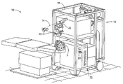
- FIG. 1 illustrates a laser ablation system which may be included or used with an embodiment of the present invention.
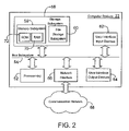
- FIG. 2 illustrates a simplified computer system according to an embodiment of the present invention.
- FIG. 3 illustrates a wavefront measurement system according to an embodiment of the present invention.
- FIG. 3A illustrates another wavefront measurement system according to an embodiment of the present invention.
- FIG. 4 is a schematic block diagram illustrating software and/or hardware modules which may be included in the computer system of FIG. 2 for use in embodiments of the invention.
- FIG. 5 is a flowchart schematically illustrating an embodiment of a method of the invention.
- FIGS. 6A and 6B are contour plots of a wavefront at two different pupil sizes.
- the present invention can be readily adapted for use with existing laser systems, wavefront measurement systems, and other optical measurement devices. While the systems, software, and methods of the present invention are described primarily in the context of a laser eye surgery system, it should be understood the present invention may be adapted for use in alternative eye treatment procedures and systems such as spectacle lenses, intraocular lenses, contact lenses, corneal ring implants, collagenous corneal tissue thermal remodeling, and the like.
- FIG. 1 illustrates a laser eye surgery system 10 of the present invention, including a laser 12 that produces a laser beam 14 .
- Laser 12 is optically coupled to laser delivery optics 16 , which directs laser beam 14 to an eye E of patient P.
- a delivery optics support structure (not shown here for clarity) extends from a frame 18 supporting laser 12 .
- a microscope 20 is mounted on the delivery optics support structure, the microscope often being used to image a cornea of eye E.
- Laser 12 generally comprises an excimer laser, ideally comprising an argon-fluorine laser producing pulses of laser light having a wavelength of approximately 193 nm.
- Laser 12 will preferably be designed to provide a feedback stabilized fluence at the patient's eye, delivered via delivery optics 16 .
- the present invention may also be useful with alternative sources of ultraviolet or infrared radiation, particularly those adapted to controllably ablate the corneal tissue without causing significant damage to adjacent and/or underlying tissues of the eye.
- sources include, but are not limited to, solid state lasers and other devices which can generate energy in the ultraviolet wavelength between about 185 and 205 nm and/or those which utilize frequency-multiplying techniques.
- an excimer laser is the illustrative source of an ablating beam, other lasers may be used in the present invention.
- Laser system 10 will generally include a computer or programmable processor 22 .
- Processor 22 may comprise (or interface with) a conventional PC system including the standard user interface devices such as a keyboard, a display monitor, and the like.
- Processor 22 will typically include an input device such as a magnetic or optical disk drive, an internet connection, or the like. Such input devices will often be used to download a computer executable code from a tangible storage media 29 embodying any of the methods of the present invention.
- Tangible storage media 29 may take the form of a floppy disk, an optical disk, a data tape, a volatile or non-volatile memory, RAM, or the like, and the processor 22 will include the memory boards and other standard components of modern computer systems for storing and executing this code.
- Tangible storage media 29 may optionally embody wavefront sensor data, wavefront gradients, a wavefront elevation map, a treatment map, a corneal elevation map, and/or an ablation table. While tangible storage media 29 will often be used directly in cooperation with a input device of processor 22 , the storage media may also be remotely operatively coupled with processor by means of network connections such as the internet, and by wireless methods such as infrared, Bluetooth, or the like.
- Laser 12 and delivery optics 16 will generally direct laser beam 14 to the eye of patient P under the direction of a computer 22 .
- Computer 22 will often selectively adjust laser beam 14 to expose portions of the cornea to the pulses of laser energy so as to effect a predetermined sculpting of the cornea and alter the refractive characteristics of the eye.
- both laser beam 14 and the laser delivery optical system 16 will be under computer control of processor 22 to effect the desired laser sculpting process, with the processor effecting (and optionally modifying) the pattern of laser pulses.
- the pattern of pulses may by summarized in machine readable data of tangible storage media 29 in the form of a treatment table, and the treatment table may be adjusted according to feedback input into processor 22 from an automated image analysis system in response to feedback data provided from an ablation monitoring system feedback system.
- the feedback may be manually entered into the processor by a system operator.
- Such feedback might be provided by integrating the wavefront measurement system described below with the laser treatment system 10 , and processor 22 may continue and/or terminate a sculpting treatment in response to the feedback, and may optionally also modify the planned sculpting based at least in part on the feedback.
- Measurement systems are further described in U.S. Pat. No. 6,315,413, the full disclosure of which is incorporated herein by reference.
- Laser beam 14 may be adjusted to produce the desired sculpting using a variety of alternative mechanisms.
- the laser beam 14 may be selectively limited using one or more variable apertures.
- An exemplary variable aperture system having a variable iris and a variable width slit is described in U.S. Pat. No. 5,713,892, the full disclosure of which is incorporated herein by reference.
- the laser beam may also be tailored by varying the size and offset of the laser spot from an axis of the eye, as described in U.S. Pat. Nos. 5,683,379, 6,203,539, and 6,331,177, the full disclosures of which are incorporated herein by reference.
- Still further alternatives are possible, including scanning of the laser beam over the surface of the eye and controlling the number of pulses and/or dwell time at each location, as described, for example, by U.S. Pat. No. 4,665,913, the full disclosure of which is incorporated herein by reference; using masks in the optical path of laser beam 14 which ablate to vary the profile of the beam incident on the cornea, as described in U.S. Pat. No. 5,807,379, the full disclosure of which is incorporated herein by reference; hybrid profile-scanning systems in which a variable size beam (typically controlled by a variable width slit and/or variable diameter iris diaphragm) is scanned across the cornea; or the like.
- the computer programs and control methodology for these laser pattern tailoring techniques are well described in the patent literature.
- laser system 10 Additional components and subsystems may be included with laser system 10 , as should be understood by those of skill in the art.
- spatial and/or temporal integrators may be included to control the distribution of energy within the laser beam, as described in U.S. Pat. No. 5,646,791, the full disclosure of which is incorporated herein by reference.
- Ablation effluent evacuators/filters, aspirators, and other ancillary components of the laser surgery system are known in the art. Further details of suitable systems for performing a laser ablation procedure can be found in commonly assigned U.S. Pat. Nos.
- Suitable systems also include commercially available refractive laser systems such as those manufactured and/or sold by Alcon, Bausch & Lomb, Nidek, WaveLight, LaserSight, Schwind, Zeiss-Meditec, and the like. Basis data can be further characterized for particular lasers or operating conditions, by taking into account localized environmental variables such as temperature, humidity, airflow, and aspiration.
- FIG. 2 is a simplified block diagram of an exemplary computer system 22 that may be used by the laser surgical system 10 of the present invention.
- Computer system 22 typically includes at least one processor 52 which may communicate with a number of peripheral devices via a bus subsystem 54 .
- peripheral devices may include a storage subsystem 56 , comprising a memory subsystem 58 and a file storage subsystem 60 , user interface input devices 62 , user interface output devices 64 , and a network interface subsystem 66 .
- Network interface subsystem 66 provides an interface to outside networks 68 and/or other devices, such as the wavefront measurement system 30 .
- User interface input devices 62 may include a keyboard, pointing devices such as a mouse, trackball, touch pad, or graphics tablet, a scanner, foot pedals, a joystick, a touchscreen incorporated into the display, audio input devices such as voice recognition systems, microphones, and other types of input devices.
- User input devices 62 will often be used to download a computer executable code from a tangible storage media 29 embodying any of the methods of the present invention.
- use of the term “input device” is intended to include a variety of conventional and proprietary devices and ways to input information into computer system 22 .
- User interface output devices 64 may include a display subsystem, a printer, a fax machine, or non-visual displays such as audio output devices.
- the display subsystem may be a cathode ray tube (CRT), a flat-panel device such as a liquid crystal display (LCD), a projection device, or the like.
- the display subsystem may also provide a non-visual display such as via audio output devices.
- output device is intended to include a variety of conventional and proprietary devices and ways to output information from computer system 22 to a user.
- Storage subsystem 56 can store the basic programming and data constructs that provide the functionality of the various embodiments of the present invention. For example, a database and modules implementing the functionality of the methods of the present invention, as described herein, may be stored in storage subsystem 56 . These software modules are generally executed by processor 52 . In a distributed environment, the software modules may be stored on a plurality of computer systems and executed by processors of the plurality of computer systems. Storage subsystem 56 typically comprises memory subsystem 58 and file storage subsystem 60 .
- Memory subsystem 58 typically includes a number of memories including a main random access memory (RAM) 70 for storage of instructions and data during program execution and a read only memory (ROM) 72 in which fixed instructions are stored.
- File storage subsystem 60 provides persistent (non-volatile) storage for program and data files, and may include tangible storage media 29 ( FIG. 1 ) which may optionally embody wavefront sensor data, wavefront gradients, a wavefront elevation map, a treatment map, and/or an ablation table.
- File storage subsystem 60 may include a hard disk drive, a floppy disk drive along with associated removable media, a Compact Digital Read Only Memory (CD-ROM) drive, an optical drive, DVD, CD-R, CD-RW, solid-state removable memory, and/or other removable media cartridges or disks.
- CD-ROM Compact Digital Read Only Memory
- One or more of the drives may be located at remote locations on other connected computers at other sites coupled to computer system 22 .
- the modules implementing the functionality of the present invention may be stored by file storage subsystem 60 .
- Bus subsystem 54 provides a mechanism for letting the various components and subsystems of computer system 22 communicate with each other as intended.
- the various subsystems and components of computer system 22 need not be at the same physical location but may be distributed at various locations within a distributed network.
- bus subsystem 54 is shown schematically as a single bus, alternate embodiments of the bus subsystem may utilize multiple busses.
- Computer system 22 itself can be of varying types including a personal computer, a portable computer, a workstation, a computer terminal, a network computer, a control system in a wavefront measurement system or laser surgical system, a mainframe, or any other data processing system. Due to the ever-changing nature of computers and networks, the description of computer system 22 depicted in FIG. 2 is intended only as a specific example for purposes of illustrating one embodiment of the present invention. Many other configurations of computer system 22 are possible having more or less components than the computer system depicted in FIG. 2 .
- wavefront measurement system 30 is configured to sense local slopes of a gradient map exiting the patient's eye.
- Devices based on the Hartmann-Shack principle generally include a lenslet array to sample the gradient map uniformly over an aperture, which is typically the exit pupil of the eye. Thereafter, the local slopes of the gradient map are analyzed so as to reconstruct the wavefront surface or map.
- one wavefront measurement system 30 includes an image source 32 , such as a laser, which projects a source image through optical tissues 34 of eye E so as to form an image 44 upon a surface of retina R.
- the image from retina R is transmitted by the optical system of the eye (e.g., optical tissues 34 ) and imaged onto a wavefront sensor 36 by system optics 37 .
- the wavefront sensor 36 communicates signals to a computer system 22 ′ for measurement of the optical errors in the optical tissues 34 and/or determination of an optical tissue ablation treatment program.
- Computer 22 ′ may include the same or similar hardware as the computer system 22 illustrated in FIGS. 1 and 2 .
- Computer system 22 ′ may be in communication with computer system 22 that directs the laser surgery system 10 , or some or all of the components of computer system 22 , 22 ′ of the wavefront measurement system 30 and laser surgery system 10 may be combined or separate. If desired, data from wavefront sensor 36 may be transmitted to a laser computer system 22 via tangible media 29 , via an I/O port, via an networking connection 66 such as an intranet or the Internet, or the like.
- Wavefront sensor 36 generally comprises a lenslet array 38 and an image sensor 40 .
- the lenslet array separates the transmitted image into an array of beamlets 42 , and (in combination with other optical components of the system) images the separated beamlets on the surface of sensor 40 .
- Sensor 40 typically comprises a charged couple device or “CCD,” and senses the characteristics of these individual beamlets, which can be used to determine the characteristics of an associated region of optical tissues 34 .
- image 44 comprises a point or small spot of light
- a location of the transmitted spot as imaged by a beamlet can directly indicate a local gradient of the associated region of optical tissue.
- Eye E generally defines an anterior orientation ANT and a posterior orientation POS.
- Image source 32 generally projects an image in a posterior orientation through optical tissues 34 onto retina R as indicated in FIG. 3 .
- Optical tissues 34 again transmit image 44 from the retina anteriorly toward wavefront sensor 36 .
- Image 44 actually formed on retina R may be distorted by any imperfections in the eye's optical system when the image source is originally transmitted by optical tissues 34 .
- image source projection optics 46 may be configured or adapted to decrease any distortion of image 44 .
- image source optics 46 may decrease lower order optical errors by compensating for spherical and/or cylindrical errors of optical tissues 34 . Higher order optical errors of the optical tissues may also be compensated through the use of an adaptive optic element, such as a deformable mirror (described below).
- Use of an image source 32 selected to define a point or small spot at image 44 upon retina R may facilitate the analysis of the data provided by wavefront sensor 36 . Distortion of image 44 may be limited by transmitting a source image through a central region 48 of optical tissues 34 which is smaller than a pupil 50 , as the central portion of the pupil may be less prone to optical errors than the peripheral portion. Regardless of the particular image source structure, it will be generally be beneficial to have a well-defined and accurately formed image 44 on retina R.
- the wavefront data may be stored in a computer readable medium 29 or a memory of the wavefront sensor system 30 in two separate arrays containing the x and y wavefront gradient values obtained from image spot analysis of the Hartmann-Shack sensor images, plus the x and y pupil center offsets from the nominal center of the Hartmann-Shack lenslet array, as measured by the pupil camera 52 ( FIG. 3 ) image.
- Such information contains all the available information on the wavefront error of the eye and is sufficient to reconstruct the wavefront or any portion of it. In such embodiments, there is no need to reprocess the Hartmann-Shack image more than once, and the data space required to store the gradient array is not large.
- the wavefront data may be stored in a memory of the wavefront sensor system in a single array or multiple arrays.
- a series of wavefront sensor data readings may be taken.
- a time series of wavefront data readings may help to provide a more accurate overall determination of the ocular tissue aberrations.
- a plurality of temporally separated wavefront sensor measurements can avoid relying on a single snapshot of the optical characteristics as the basis for a refractive correcting procedure.
- Still further alternatives are also available, including taking wavefront sensor data of the eye with the eye in differing configurations, positions, and/or orientations.
- a patient will often help maintain alignment of the eye with wavefront measurement system 30 by focusing on a fixation target, as described in U.S. Pat. No. 6,004,313, the full disclosure of which is incorporated herein by reference.
- a fixation target as described in U.S. Pat. No. 6,004,313, the full disclosure of which is incorporated herein by reference.
- optical characteristics of the eye may be determined while the eye accommodates or adapts to image a field of view at a varying distance and/or angles.
- the location of the optical axis of the eye may be verified by reference to the data provided from a pupil camera 52 .
- a pupil camera 52 images pupil 50 so as to determine a position of the pupil for registration of the wavefront sensor data relative to the optical tissues.
- FIG. 3A An alternative embodiment of a wavefront measurement system is illustrated in FIG. 3A .
- the major components of the system of FIG. 3A are similar to those of FIG. 3 .
- FIG. 3A includes an adaptive optical element 98 in the form of a deformable mirror.
- the source image is reflected from deformable mirror 98 during transmission to retina R, and the deformable mirror is also along the optical path used to form the transmitted image between retina R and imaging sensor 40 .
- Deformable mirror 98 can be controllably deformed by computer system 22 to limit distortion of the image formed on the retina or of subsequent images formed of the images formed on the retina, and may enhance the accuracy of the resultant wavefront data.
- the structure and use of the system of FIG. 3A are more fully described in U.S. Pat. No. 6,095,651, the full disclosure of which is incorporated herein by reference.
- the components of an embodiment of a wavefront measurement system for measuring the eye and ablations may comprise elements of a VISX WaveScan® system, available from VISX, I NCORPORATED of Santa Clara, Calif.
- VISX WaveScan® available from VISX, I NCORPORATED of Santa Clara, Calif.
- One embodiment includes a WaveScan® with a deformable mirror as described above.
- An alternate embodiment of a wavefront measuring system is described in U.S. Pat. No. 6,271,915, the full disclosure of which is incorporated herein by reference. It is appreciated that any wavefront aberrometer could be employed for use with the present invention.
- FIGS. 4 and 5 schematically illustrate embodiments of hardware and/or software modules of computer system 22 and a related method, respectively. These embodiments can generate scaled wavefront reconstruction data suitable for analysis of a patient's eye when a pupil of the patient changes size from a relatively large wavefront measurement pupil size to a smaller size. Structures and methods for reconstructing a wavefront and/or generating prescriptions from wavefront data are well documented in a variety of patent literature, including U.S. patent application Ser. No. 10/738,358, as filed on Dec. 5, 2003 and entitled “Presbyopia Correction Using Patient Data;” and Ser. No.
- W(Rr, ⁇ ) represents the ocular aberrations of a human eye measured as the optical path difference
- the wavefront can be decomposed into a set of complete and orthogonal basis functions as:
- a i is the coefficient of the ith basis function F i (r, ⁇ ) and R is the pupil radius.
- r is the radial variable in the polar coordinates defining the unit circle. Zernike polynomials have been widely used as a set of basis functions because of their connection to classical aberrations in optical systems with circular apertures.
- Both the single-index i and the double-index m and n may be referred to herein. These two different indexing schemes can be effectively identical. For example, the decision whether to use a single or double index may be based on convenience.
- the ocular aberrations of the pupil with the smaller radius, R 2 are the same as the aberrations of the area defined by radius R 2 when the pupil size is R 1 ; i.e., the aberrations do not change when the pupil size changes.
- FIGS. 6A and 6B graphically illustrate contour plots of a wavefront map with pupil radius R 1 (in FIG. 6A ) and the wavefront map when the pupil size constricts to pupil radius R 1 to R 2 (in FIG. 6B ).
- the two maps are in the same scale. Units are in micrometers of optical path difference. Note that the portion of the wavefront defined by R 2 in FIG. 6A is the same as the plot in FIG. 6B .
- Equation (9) Derivation of Eq. (9) comes from the definition of wavefront expansion into basis functions. Equation (9) can be applied to any set of basis functions. If the triangular function is the same in both sides of Eq. (9), i.e., there is no rotation, after Eq. (2) is applied the relationship between the sets of coefficients ⁇ a i ⁇ and ⁇ b i ⁇ is
- ⁇ i 0 ( N - n ) / 2 ⁇ b n - 2 ⁇ i m ⁇ ( - 1 ) i ⁇ n + 2 ⁇ i + 1 ⁇ ( n + i ) ! ⁇ r n i ! ⁇ [ ( n + 2 ⁇ i + m ) / 2 - i ] ! ⁇ [ ( n + 2 ⁇ i - m ) / 2 - i ] ! ⁇ [ ( n + 2 ⁇ i - m ) / 2 - i ] !
- index i was used to prevent confusion with index s used in Eq. (11), although both i and s have the same summation structure. Because Eq. (14) was derived for r n only, m can be any integer from ⁇ n to n with a step of 2.
- Equation (16) is the final recursive formula.
- Equation (16) is the final recursive formula.
- relations between ⁇ b i ⁇ and ⁇ a i ⁇ can be obtained analytically.
- Eq. (16) is applied to replace b n+2i m .
- the coefficient of the (n+2)th order can be written as
- Eq. (18) can be derived (see the derivation of Eq. 19 below) as
- the dioptric power of human eyes is typically the power desired from a thin lens with a uniform optical power to give the subject the best distance vision.
- This dioptric power may be independent of pupil size.
- dioptric power can change when pupil size changes.
- the instantaneous power that is dependent on pupil size is herein called effective power.
- wavefronts of radially symmetric aspheric optical surfaces are not represented by Zernike polynomials but by power series. In this case, the wavefront is written as
- Equation (22) indicates that when higher-order spherical aberrations exist, the effective power is no longer determined only by the defocus term.
- Such embodiments may optionally include (and/or make use of) some or all of the structures described above regarding FIGS. 1-3A , optionally per the exemplary embodiments of FIGS. 4 and 5 .
- a wide variety of alternative embodiments may also be implemented, optionally using any of the wide variety of known eye measurement and refraction altering techniques, new eye measurement and refraction altering techniques which are developed, or a combination of both.
- Exemplary embodiments may, for example, be used for calculation of effective powers of an eye at differing pupil sizes and/or locations, including those induced by differing viewing distances (and/or other viewing conditions). As explained in more detail US Patent Publication No. 20040169820, the full disclosure of which is incorporated herein by reference, such calculations of effective powers may have advantages for treatment of presbyopia.
- b n + 2 m ⁇ n + 2 ⁇ a n + 2 m - ( n + 5 ) ⁇ ( n + 3 ) ⁇ ( ⁇ n + 2 ⁇ a n + 4 m - b n + 4 m ) + 1 2 ⁇ ( n + 4 ) ⁇ ( n + 7 ) ⁇ ( n + 3 ) ⁇ ( ⁇ n + 2 ⁇ a n + 6 m - b n + 6 m ) - 1 6 ⁇ ( n + 5 ) ⁇ ( n + 4 ) ⁇ ( n + 9 ) ⁇ ( n + 3 ) ⁇ ( ⁇ n + 2 ⁇ a n + 8 m - b n + 8 m ) + ... + ( - 1 ) ( N - n - 3 ) / 2 ⁇ N ⁇ ( n + 3 ) [ ( N - n - 3 ) [
- N ⁇ n is even. If N ⁇ n is odd, an adjustment similar to that in Eq. (A2) can be done. To simplify the process, formulas for N ⁇ n being odd will not be given for the next two cases.
- b n + 4 m ⁇ n + 4 ⁇ a n + 4 m - ( n + 7 ) ⁇ ( n + 5 ) ⁇ ( ⁇ n + 4 ⁇ a n + 6 m - b n + 6 m ) + 1 2 ⁇ ( n + 6 ) ⁇ ( n + 9 ) ⁇ ( n + 5 ) ⁇ ( ⁇ n + 4 ⁇ a n + 8 m - b n + 8 m ) - 1 6 ⁇ ( n + 7 ) ⁇ ( n + 6 ) ⁇ ( n + 11 ) ⁇ ( n + 5 ) ⁇ ( ⁇ n + 4 ⁇ a n + 10 m - b n + 10 m ) + ... + ( - 1 ) ( N - n ) / 2 - 2 ⁇ ( N + 1 ) ⁇ ( n + 5 ) [ ( N - n
- b n + 6 m ⁇ n + 6 ⁇ a n + 6 m - ( n + 9 ) ⁇ ( n + 7 ) ⁇ ( ⁇ n + 6 ⁇ a n + 8 m - b n + 8 m ) + 1 2 ⁇ ( n + 8 ) ⁇ ( n + 11 ) ⁇ ( n + 7 ) ⁇ ( ⁇ n + 6 ⁇ a n + 10 m - b n + 10 m ) - 1 6 ⁇ ( n + 9 ) ⁇ ( n + 8 ) ⁇ ( n + 11 ) ⁇ ( n + 7 ) ⁇ ( ⁇ n + 6 ⁇ a n + 12 m - b n + 12 m ) + ... + ( - 1 ) ( N - n ) / 2 - 3 ⁇ ( N + 1 ) ⁇ ( n + 7 ) [ ( N - n
- Eq. (12) or Eq. (13) depending on whether N ⁇ n is even or odd.
- Eqs. (12) and (13) and combinations of terms for a n m , a n+2 m , a n+4 m , . . . , Eq. (16) becomes
- b n m ⁇ n ⁇ a n m - ( n + 3 ) ⁇ ( n + 1 ) ⁇ ⁇ n ⁇ ( 1 - ⁇ ⁇ 2 ) ⁇ a n + 2 m + 1 2 ⁇ [ ( n + 2 ) - 2 ⁇ ( n + 3 ) ⁇ ⁇ 2 ⁇ + ( n + 4 ) ⁇ ⁇ 4 ] ⁇ ( n + 5 ) ⁇ ( n + 1 ) ⁇ ⁇ n ⁇ a n + 4 m - 1 6 ⁇ [ ( n + 2 ) ⁇ ( n + 3 ) - 3 ⁇ ( n + 3 ) ⁇ ( n + 4 ) ⁇ ⁇ 2 ⁇ + 3 ⁇ ( n + 4 ) ⁇ ( n + 5 ) ⁇ ⁇ 4 ⁇ - ( n + 5 ) ⁇ ( n + 6 ⁇ - ( n + 5 ) ⁇
- Each of the above calculations may be performed using a computer or other processor having hardware, software, and/or firmware.
- the various method steps may be performed by modules, and the modules may comprise any of a wide variety of digital and/or analog data processing hardware and/or software arranged to perform the method steps described herein.
- the modules optionally comprising data processing hardware adapted to perform one or more of these steps by having appropriate machine programming code associated therewith, the modules for two or more steps (or portions of two or more steps) being integrated into a single processor board or separated into different processor boards in any of a wide variety of integrated and/or distributed processing architectures.
- These methods and systems will often employ a tangible media embodying machine-readable code with instructions for performing the method steps described above.
- Suitable tangible media may comprise a memory (including a volatile memory and/or a non-volatile memory), a storage media (such as a magnetic recording on a floppy disk, a hard disk, a tape, or the like; on an optical memory such as a CD, a CD-R/W, a CD-ROM, a DVD, or the like; or any other digital or analog storage media), or the like.
- a memory including a volatile memory and/or a non-volatile memory
- a storage media such as a magnetic recording on a floppy disk, a hard disk, a tape, or the like; on an optical memory such as a CD, a CD-R/W, a CD-ROM, a DVD, or the like; or any other digital or analog storage media, or the like.
- output data can be generated by the systems and methods of the present invention. Such outputs may be used for a variety of research, comparison, prediction, diagnostic, and verification operations.
- the outputs may be evaluated directly, or they may be used as input into the system for further analysis.
- the outputs will be used to model the effect of an ocular treatment prior to application.
- the outputs will be used to evaluate the effect of an ocular treatment after application.
- the outputs may also be used to design ocular treatments.
Abstract
Description
Z i(r,θ)=R n {|m|}(r)θm(θ), (Eq. 2)
where n and m denote the radial degree and the azimuthal frequency, respectively; the radial polynomials are defined as:
and the triangular functions as:
where ai is the ith Zernike coefficient representing the Zernike expansion into the pupil when the pupil radius is R1. Similarly, the entire wavefront over the pupil with radius R2 can be written as:
where bi is the ith Zernike coefficient representing the Zernike expansion into the pupil when the pupil radius is R2. The next step is to determine the relationship of {bi} to {ai}.
As shown in
W 1′(R 1 r,θ)=W 2(R 2 r,θ) (Eq. 8)
And so, from Eqs. (6)-(8), it is found that
Substituting Rn m(r) from Eq. (3) to Eq. (10) yields
where N is the total number of orders used for the expansion. Expanding this equation into a radial series yields radial powers of r from 0 to N, resulting in (N+1) equations. This leads to a solution for (N+1) relations between an m and bn m.
bN m=εNaN m. (Eq. 12)
b N-1 m=εN-1 a N-1 m (Eq. 13)
where R stands for the instantaneous pupil radius in millimeters when the instantaneous coefficient of defocus term a2 0 is given in micrometers to get the effective power of the diopters. If a wavefront map is defined in radius R with a set of Zernike polynomials, when the pupil constricts, the smaller map is then redefined with a new set of Zernike polynomials, and it will have a set of Zernike coefficients that is different from the original set.
where R stands for the pupil radius, r is the radial variable in polar coordinates that defines the unit circle, and N is the maximum radial power. The coefficients {a2n} of the power series of Eq. (23) can be converted into Zernike polynomials so that the effective power can be written as
where it is assume that N−n is even. If N−n is odd, Eq. (A1) becomes
Z i(r,θ)=R n {|m|}(r)θm(θ), (Eq. B1)
where the unnormalized Zernike radial polynomials are defined as
Claims (18)
Priority Applications (8)
| Application Number | Priority Date | Filing Date | Title |
|---|---|---|---|
| US11/676,094 US7717562B2 (en) | 2006-02-24 | 2007-02-16 | Scaling Zernike coefficients to smaller pupil sizes for refractive treatments |
| US12/722,881 US7887187B2 (en) | 2006-02-24 | 2010-03-12 | Scaling zernike coefficients to smaller pupil sizes for refractive treatments |
| US13/008,488 US8454160B2 (en) | 2006-02-24 | 2011-01-18 | Zone extension systems and methods |
| US13/903,239 US9050030B2 (en) | 2006-02-24 | 2013-05-28 | Zone extension systems and methods |
| US14/339,316 US9370298B2 (en) | 2006-02-24 | 2014-07-23 | Induced high order aberrations corresponding to geometrical transformations |
| US14/711,535 US9658468B2 (en) | 2006-02-24 | 2015-05-13 | Zone extension systems and methods |
| US15/154,214 US10070783B2 (en) | 2006-02-24 | 2016-05-13 | Induced high order aberrations corresponding to geometrical transformations |
| US15/438,582 US10191299B2 (en) | 2006-02-24 | 2017-02-21 | Zone extension systems and methods |
Applications Claiming Priority (2)
| Application Number | Priority Date | Filing Date | Title |
|---|---|---|---|
| US77628906P | 2006-02-24 | 2006-02-24 | |
| US11/676,094 US7717562B2 (en) | 2006-02-24 | 2007-02-16 | Scaling Zernike coefficients to smaller pupil sizes for refractive treatments |
Related Child Applications (2)
| Application Number | Title | Priority Date | Filing Date |
|---|---|---|---|
| US12/722,881 Continuation US7887187B2 (en) | 2006-02-24 | 2010-03-12 | Scaling zernike coefficients to smaller pupil sizes for refractive treatments |
| US12/722,811 Continuation US20110220332A1 (en) | 2006-02-24 | 2010-03-12 | Micro channel device temperature control |
Publications (2)
| Publication Number | Publication Date |
|---|---|
| US20070201001A1 US20070201001A1 (en) | 2007-08-30 |
| US7717562B2 true US7717562B2 (en) | 2010-05-18 |
Family
ID=38443628
Family Applications (2)
| Application Number | Title | Priority Date | Filing Date |
|---|---|---|---|
| US11/676,094 Active 2028-03-19 US7717562B2 (en) | 2006-02-24 | 2007-02-16 | Scaling Zernike coefficients to smaller pupil sizes for refractive treatments |
| US12/722,881 Active US7887187B2 (en) | 2006-02-24 | 2010-03-12 | Scaling zernike coefficients to smaller pupil sizes for refractive treatments |
Family Applications After (1)
| Application Number | Title | Priority Date | Filing Date |
|---|---|---|---|
| US12/722,881 Active US7887187B2 (en) | 2006-02-24 | 2010-03-12 | Scaling zernike coefficients to smaller pupil sizes for refractive treatments |
Country Status (1)
| Country | Link |
|---|---|
| US (2) | US7717562B2 (en) |
Cited By (9)
| Publication number | Priority date | Publication date | Assignee | Title |
|---|---|---|---|---|
| US20090006508A1 (en) * | 2007-06-27 | 2009-01-01 | Gerhard Youssefi | Method and apparatus for extrapolating diagnostic data |
| US20100198567A1 (en) * | 2006-02-24 | 2010-08-05 | Amo Manufacturing Usa, Llc | Scaling zernike coefficients to smaller pupil sizes for refractive treatments |
| US20100253909A1 (en) * | 2006-02-24 | 2010-10-07 | Amo Development, Llc | Induced high order aberrations corresponding to geometrical transformations |
| US20110149241A1 (en) * | 2006-02-24 | 2011-06-23 | Amo Development, Llc | Zone extension systems and methods |
| US7967436B2 (en) | 2007-08-01 | 2011-06-28 | Amo Development Llc. | Wavefront refractions and high order aberration correction when wavefront maps involve geometrical transformations |
| US9122926B2 (en) | 2012-07-19 | 2015-09-01 | Honeywell International Inc. | Iris recognition using localized Zernike moments |
| US9195074B2 (en) | 2012-04-05 | 2015-11-24 | Brien Holden Vision Institute | Lenses, devices and methods for ocular refractive error |
| US9201250B2 (en) | 2012-10-17 | 2015-12-01 | Brien Holden Vision Institute | Lenses, devices, methods and systems for refractive error |
| US9541773B2 (en) | 2012-10-17 | 2017-01-10 | Brien Holden Vision Institute | Lenses, devices, methods and systems for refractive error |
Families Citing this family (8)
| Publication number | Priority date | Publication date | Assignee | Title |
|---|---|---|---|---|
| US9504376B2 (en) * | 2009-12-22 | 2016-11-29 | Amo Wavefront Sciences, Llc | Optical diagnosis using measurement sequence |
| US8205987B2 (en) * | 2010-04-20 | 2012-06-26 | Carl Zeiss Vision Inc. | Method for optimizing a spectacle lens for the wavefront aberrations of an eye and lens |
| US10582846B2 (en) | 2010-12-30 | 2020-03-10 | Amo Wavefront Sciences, Llc | Method and system for eye measurements and cataract surgery planning using vector function derived from prior surgeries |
| EP3213724B1 (en) | 2010-12-30 | 2019-09-18 | Amo Wavefront Sciences, LLC | Improved treatment planning method and system for controlling laser refractive surgery |
| US10583039B2 (en) | 2010-12-30 | 2020-03-10 | Amo Wavefront Sciences, Llc | Method and system for eye measurements and cataract surgery planning using vector function derived from prior surgeries |
| US10582847B2 (en) | 2010-12-30 | 2020-03-10 | Amo Wavefront Sciences, Llc | Method and system for eye measurements and cataract surgery planning using vector function derived from prior surgeries |
| CN103559688B (en) * | 2013-10-29 | 2016-09-07 | 电子科技大学 | distortion correction method based on wavefront image compensation |
| WO2018147834A1 (en) * | 2017-02-07 | 2018-08-16 | Carl Zeiss Vision International Gmbh | Prescription determination |
Citations (28)
| Publication number | Priority date | Publication date | Assignee | Title |
|---|---|---|---|---|
| US4665913A (en) | 1983-11-17 | 1987-05-19 | Lri L.P. | Method for ophthalmological surgery |
| US4669466A (en) | 1985-01-16 | 1987-06-02 | Lri L.P. | Method and apparatus for analysis and correction of abnormal refractive errors of the eye |
| US4732148A (en) | 1983-11-17 | 1988-03-22 | Lri L.P. | Method for performing ophthalmic laser surgery |
| US4770172A (en) | 1983-11-17 | 1988-09-13 | Lri L.P. | Method of laser-sculpture of the optically used portion of the cornea |
| US4773414A (en) | 1983-11-17 | 1988-09-27 | Lri L.P. | Method of laser-sculpture of the optically used portion of the cornea |
| US5108388A (en) | 1983-12-15 | 1992-04-28 | Visx, Incorporated | Laser surgery method |
| US5163934A (en) | 1987-08-05 | 1992-11-17 | Visx, Incorporated | Photorefractive keratectomy |
| US5207668A (en) | 1983-11-17 | 1993-05-04 | Visx Incorporated | Method for opthalmological surgery |
| US5219343A (en) | 1983-11-17 | 1993-06-15 | Visx Incorporated | Apparatus for performing ophthalmogolical surgery |
| US5646791A (en) | 1995-01-04 | 1997-07-08 | Visx Incorporated | Method and apparatus for temporal and spatial beam integration |
| US5683379A (en) | 1992-10-01 | 1997-11-04 | Chiron Technolas Gmbh Ophthalmologische Systeme | Apparatus for modifying the surface of the eye through large beam laser polishing and method of controlling the apparatus |
| US5713892A (en) | 1991-08-16 | 1998-02-03 | Visx, Inc. | Method and apparatus for combined cylindrical and spherical eye corrections |
| US5807379A (en) | 1983-11-17 | 1998-09-15 | Visx, Incorporated | Ophthalmic method and apparatus for laser surgery of the cornea |
| US6004313A (en) | 1998-06-26 | 1999-12-21 | Visx, Inc. | Patient fixation system and method for laser eye surgery |
| US6095651A (en) | 1996-12-23 | 2000-08-01 | University Of Rochester | Method and apparatus for improving vision and the resolution of retinal images |
| US6203539B1 (en) | 1993-05-07 | 2001-03-20 | Visx, Incorporated | Method and system for laser treatment of refractive errors using offset imaging |
| US6271915B1 (en) | 1996-11-25 | 2001-08-07 | Autonomous Technologies Corporation | Objective measurement and correction of optical systems using wavefront analysis |
| US6315413B1 (en) | 1997-05-27 | 2001-11-13 | Visx, Incorporated | Systems and methods for imaging corneal profiles |
| US6331177B1 (en) | 1998-04-17 | 2001-12-18 | Visx, Incorporated | Multiple beam laser sculpting system and method |
| WO2002098290A2 (en) | 2001-04-18 | 2002-12-12 | Bausch & Lomb Incorporated | Objective measurement of eye refraction |
| US20030225399A1 (en) | 2002-02-11 | 2003-12-04 | Visx, Inc. | Closed loop system and method for testing a performance of a laser system |
| US20040169820A1 (en) | 2002-12-06 | 2004-09-02 | Visx, Incorporated | Presbyopia correction using patient data |
| WO2004113958A2 (en) | 2003-06-16 | 2004-12-29 | Visx, Incorporated | Methods and devices for registering optical measurement datasets of an optical system |
| US20050270491A1 (en) | 2002-12-06 | 2005-12-08 | Visx, Incorporated | Residual accommodation threshold for correction of presbyopia and other presbyopia correction using patient data |
| US20080117231A1 (en) | 2006-11-19 | 2008-05-22 | Tom Kimpe | Display assemblies and computer programs and methods for defect compensation |
| US20080198331A1 (en) | 2004-07-19 | 2008-08-21 | Massachusetts Eye & Ear Infirmary, A Massachusetts Corporation | Ocular wavefront-correction profiling |
| US20090036980A1 (en) * | 2000-05-23 | 2009-02-05 | Amo Groningen Bv | Methods of obtaining ophthalmic lenses providing the eye with reduced aberrations |
| US20090086163A1 (en) * | 2002-12-06 | 2009-04-02 | Amo Manufacturing Usa, Llc. | Compound modulation transfer function for laser surgery and other optical applications |
Family Cites Families (4)
| Publication number | Priority date | Publication date | Assignee | Title |
|---|---|---|---|---|
| US7331674B2 (en) * | 2005-09-02 | 2008-02-19 | Visx, Incorporated | Calculating Zernike coefficients from Fourier coefficients |
| US7695136B2 (en) | 2007-08-01 | 2010-04-13 | Amo Development, Llc. | Wavefront refractions and high order aberration correction when wavefront maps involve geometrical transformations |
| US7717562B2 (en) | 2006-02-24 | 2010-05-18 | Amo Development Llc. | Scaling Zernike coefficients to smaller pupil sizes for refractive treatments |
| US7592882B2 (en) * | 2007-02-22 | 2009-09-22 | John Mezzalingua Associates, Inc. | Dual bandstop filter with enhanced upper passband response |
-
2007
- 2007-02-16 US US11/676,094 patent/US7717562B2/en active Active
-
2010
- 2010-03-12 US US12/722,881 patent/US7887187B2/en active Active
Patent Citations (31)
| Publication number | Priority date | Publication date | Assignee | Title |
|---|---|---|---|---|
| US5219343A (en) | 1983-11-17 | 1993-06-15 | Visx Incorporated | Apparatus for performing ophthalmogolical surgery |
| US5807379A (en) | 1983-11-17 | 1998-09-15 | Visx, Incorporated | Ophthalmic method and apparatus for laser surgery of the cornea |
| US4732148A (en) | 1983-11-17 | 1988-03-22 | Lri L.P. | Method for performing ophthalmic laser surgery |
| US4770172A (en) | 1983-11-17 | 1988-09-13 | Lri L.P. | Method of laser-sculpture of the optically used portion of the cornea |
| US4773414A (en) | 1983-11-17 | 1988-09-27 | Lri L.P. | Method of laser-sculpture of the optically used portion of the cornea |
| US4665913A (en) | 1983-11-17 | 1987-05-19 | Lri L.P. | Method for ophthalmological surgery |
| US5207668A (en) | 1983-11-17 | 1993-05-04 | Visx Incorporated | Method for opthalmological surgery |
| US5108388B1 (en) | 1983-12-15 | 2000-09-19 | Visx Inc | Laser surgery method |
| US5108388A (en) | 1983-12-15 | 1992-04-28 | Visx, Incorporated | Laser surgery method |
| US4669466A (en) | 1985-01-16 | 1987-06-02 | Lri L.P. | Method and apparatus for analysis and correction of abnormal refractive errors of the eye |
| US5163934A (en) | 1987-08-05 | 1992-11-17 | Visx, Incorporated | Photorefractive keratectomy |
| US5713892A (en) | 1991-08-16 | 1998-02-03 | Visx, Inc. | Method and apparatus for combined cylindrical and spherical eye corrections |
| US5683379A (en) | 1992-10-01 | 1997-11-04 | Chiron Technolas Gmbh Ophthalmologische Systeme | Apparatus for modifying the surface of the eye through large beam laser polishing and method of controlling the apparatus |
| US6203539B1 (en) | 1993-05-07 | 2001-03-20 | Visx, Incorporated | Method and system for laser treatment of refractive errors using offset imaging |
| US5646791A (en) | 1995-01-04 | 1997-07-08 | Visx Incorporated | Method and apparatus for temporal and spatial beam integration |
| US6271915B1 (en) | 1996-11-25 | 2001-08-07 | Autonomous Technologies Corporation | Objective measurement and correction of optical systems using wavefront analysis |
| US6095651A (en) | 1996-12-23 | 2000-08-01 | University Of Rochester | Method and apparatus for improving vision and the resolution of retinal images |
| US6315413B1 (en) | 1997-05-27 | 2001-11-13 | Visx, Incorporated | Systems and methods for imaging corneal profiles |
| US6331177B1 (en) | 1998-04-17 | 2001-12-18 | Visx, Incorporated | Multiple beam laser sculpting system and method |
| US6004313A (en) | 1998-06-26 | 1999-12-21 | Visx, Inc. | Patient fixation system and method for laser eye surgery |
| US20090036980A1 (en) * | 2000-05-23 | 2009-02-05 | Amo Groningen Bv | Methods of obtaining ophthalmic lenses providing the eye with reduced aberrations |
| WO2002098290A2 (en) | 2001-04-18 | 2002-12-12 | Bausch & Lomb Incorporated | Objective measurement of eye refraction |
| US20030225399A1 (en) | 2002-02-11 | 2003-12-04 | Visx, Inc. | Closed loop system and method for testing a performance of a laser system |
| US7434936B2 (en) | 2002-12-06 | 2008-10-14 | Amo Manufacturing Usa, Llc | Residual accommodation threshold for correction of presbyopia and other presbyopia correction using patient data |
| US20040169820A1 (en) | 2002-12-06 | 2004-09-02 | Visx, Incorporated | Presbyopia correction using patient data |
| US20050270491A1 (en) | 2002-12-06 | 2005-12-08 | Visx, Incorporated | Residual accommodation threshold for correction of presbyopia and other presbyopia correction using patient data |
| US7293873B2 (en) | 2002-12-06 | 2007-11-13 | Visx, Incorporated | Presbyopia correction using patient data |
| US20090086163A1 (en) * | 2002-12-06 | 2009-04-02 | Amo Manufacturing Usa, Llc. | Compound modulation transfer function for laser surgery and other optical applications |
| WO2004113958A2 (en) | 2003-06-16 | 2004-12-29 | Visx, Incorporated | Methods and devices for registering optical measurement datasets of an optical system |
| US20080198331A1 (en) | 2004-07-19 | 2008-08-21 | Massachusetts Eye & Ear Infirmary, A Massachusetts Corporation | Ocular wavefront-correction profiling |
| US20080117231A1 (en) | 2006-11-19 | 2008-05-22 | Tom Kimpe | Display assemblies and computer programs and methods for defect compensation |
Non-Patent Citations (14)
| Title |
|---|
| Bara, Salvador et al. "Direct Transformation of Zernike Eye Aberration Coefficients Between Scaled, Rotaed, and/or Displaced pupils", Journal of the Optical Society of America, 2006, vol. 23, No. 9, Sep. 2006, pp. 2061-2066. |
| Campbell, Charles E., "Matrix Method to Find A New Set of Zernike Coefficients From an Original Set When the Aperture Radius is Changed", Journal of the Optical Society of America, 2003, vol. 20, No. 2, Feb. 2003, pp. 209-217. |
| Dai, G.M., "Scaling Zernike Expansion Coefficients to Smaller Pupil Sizes: A Simpler Formula", J. Opt. Soc. Am. A. Opt. Image Sci. Vis., Mar. 23 (3): 539-43 (2006). |
| Dai, Guang-Ming, "Scaling Zernike Expansion Coefficients to Smaller Pupil Sizes: A Simpler Formula", Journal of the Optical Society of America, 2006, vol. 23, No. 3, Mar. 2006, pp. 539-543. |
| Goldberg, Kenneth et al., "Wave-Front Measurement Errors From Restricted Concentric Subdomains", Journal of the Optical Society of America, 2001, vol. 18, No. 9, Sep. 2001, pp. 2146-2152. |
| Guirao, Antonio et al., "Effect of Rotation and Translation on the Expected Benefit of an Ideal Method to Correct the Eye's Higher-Order Aberrations", Journal of the Optical Society of America, 2001, vol. 18, No. 5, May 2001, pp. 1003-1015. |
| Janssen, Augustus et al., "Concise Formula for the Zernike Coefficients of Scaled Pupils", Journal of Microlithography, Microfabrication, and Microsystems, Jul.-Sep. 2006/vol. 5(3), pp. 30501-1 to 30501-3. |
| Lundstrom, Linda et al., "Transformation of Zernike Coefficients: Scaled, Translated, and Rotated Wavefronts With Circular and Elliptical Pupils", Journal of the Optical Society of America, vol. 24, No. 3, Mar. 2007, pp. 569-577. |
| PCT International Search Report and Written Opinion mailed Dec. 15, 2008, International Application No. PCT/US2008/071794, 19 pages. |
| Schweigerling, Jim, "Scaling Zernike expansion coefficients to different pupil sizes", Journal of the Optical Society of America, 2002, vol. 19, No. 10, Oct. 2002, pp. 1937-1945. |
| Schwiegerling, Jim, "Scaling Zernike Expansion Coefficients to Different Pupil Sizes", J. Opt. Soc. Am. A. Opt. Image Sci. Vis., 2002, Oct., 19(10): 1937-45. |
| Shu, Huazhong et al., "General Method to Derive the Relationship Between Two Sets of Zernike Coefficients Corresponding to Different Aperture Sizes", Journal of the Optical Society of America, 2006, vol. 23, No. 8, Aug. 2006, pp. 1960-1966. |
| Wilson, M. A. et al., "The Julius F. Neumueller Award in Optics, 1989: Change of Pupil Centration with Change of Illumination and Pupil Size", Optom. and Vis. Sci., 69, No. 2: 129-136 (1992). |
| Yang, Yabo et al., "Pupil LOcation Under Mesopic, Photopic, and Pharmacologically Dilated Conditions", Investigative Opthalmalogy & Visual Science, Jul. 2002, vol. 43, No. 7, pp. 2508-2512. |
Cited By (33)
| Publication number | Priority date | Publication date | Assignee | Title |
|---|---|---|---|---|
| US8454160B2 (en) | 2006-02-24 | 2013-06-04 | Amo Development, Llc | Zone extension systems and methods |
| US9050030B2 (en) | 2006-02-24 | 2015-06-09 | Amo Development, Llc | Zone extension systems and methods |
| US20100253909A1 (en) * | 2006-02-24 | 2010-10-07 | Amo Development, Llc | Induced high order aberrations corresponding to geometrical transformations |
| US7887187B2 (en) | 2006-02-24 | 2011-02-15 | Amo Manufacturing Usa, Llc. | Scaling zernike coefficients to smaller pupil sizes for refractive treatments |
| US20110149241A1 (en) * | 2006-02-24 | 2011-06-23 | Amo Development, Llc | Zone extension systems and methods |
| US9370298B2 (en) | 2006-02-24 | 2016-06-21 | Amo Development, Llc | Induced high order aberrations corresponding to geometrical transformations |
| US20100198567A1 (en) * | 2006-02-24 | 2010-08-05 | Amo Manufacturing Usa, Llc | Scaling zernike coefficients to smaller pupil sizes for refractive treatments |
| US10070783B2 (en) | 2006-02-24 | 2018-09-11 | Amo Development, Llc | Induced high order aberrations corresponding to geometrical transformations |
| US9658468B2 (en) | 2006-02-24 | 2017-05-23 | Amo Development, Llc | Zone extension systems and methods |
| US10191299B2 (en) | 2006-02-24 | 2019-01-29 | Amo Development, Llc | Zone extension systems and methods |
| US8474974B2 (en) | 2006-02-24 | 2013-07-02 | Amo Development Llc. | Induced high order aberrations corresponding to geometrical transformations |
| US20090006508A1 (en) * | 2007-06-27 | 2009-01-01 | Gerhard Youssefi | Method and apparatus for extrapolating diagnostic data |
| US8740381B2 (en) | 2007-06-27 | 2014-06-03 | Bausch & Lomb Incorporated | Method and apparatus for extrapolating diagnostic data |
| US8827449B2 (en) | 2007-08-01 | 2014-09-09 | Amo Development Llc | Induced high order aberrations corresponding to geometrical transformations |
| US7967436B2 (en) | 2007-08-01 | 2011-06-28 | Amo Development Llc. | Wavefront refractions and high order aberration correction when wavefront maps involve geometrical transformations |
| US10466507B2 (en) | 2012-04-05 | 2019-11-05 | Brien Holden Vision Institute Limited | Lenses, devices and methods for ocular refractive error |
| US10838235B2 (en) | 2012-04-05 | 2020-11-17 | Brien Holden Vision Institute Limited | Lenses, devices, and methods for ocular refractive error |
| US9575334B2 (en) | 2012-04-05 | 2017-02-21 | Brien Holden Vision Institute | Lenses, devices and methods of ocular refractive error |
| US9535263B2 (en) | 2012-04-05 | 2017-01-03 | Brien Holden Vision Institute | Lenses, devices, methods and systems for refractive error |
| US11809024B2 (en) | 2012-04-05 | 2023-11-07 | Brien Holden Vision Institute Limited | Lenses, devices, methods and systems for refractive error |
| US11644688B2 (en) | 2012-04-05 | 2023-05-09 | Brien Holden Vision Institute Limited | Lenses, devices and methods for ocular refractive error |
| US9195074B2 (en) | 2012-04-05 | 2015-11-24 | Brien Holden Vision Institute | Lenses, devices and methods for ocular refractive error |
| US10203522B2 (en) | 2012-04-05 | 2019-02-12 | Brien Holden Vision Institute | Lenses, devices, methods and systems for refractive error |
| US10209535B2 (en) | 2012-04-05 | 2019-02-19 | Brien Holden Vision Institute | Lenses, devices and methods for ocular refractive error |
| US10948743B2 (en) | 2012-04-05 | 2021-03-16 | Brien Holden Vision Institute Limited | Lenses, devices, methods and systems for refractive error |
| US9122926B2 (en) | 2012-07-19 | 2015-09-01 | Honeywell International Inc. | Iris recognition using localized Zernike moments |
| US11320672B2 (en) | 2012-10-07 | 2022-05-03 | Brien Holden Vision Institute Limited | Lenses, devices, systems and methods for refractive error |
| US10534198B2 (en) | 2012-10-17 | 2020-01-14 | Brien Holden Vision Institute Limited | Lenses, devices, methods and systems for refractive error |
| US10520754B2 (en) | 2012-10-17 | 2019-12-31 | Brien Holden Vision Institute Limited | Lenses, devices, systems and methods for refractive error |
| US9541773B2 (en) | 2012-10-17 | 2017-01-10 | Brien Holden Vision Institute | Lenses, devices, methods and systems for refractive error |
| US11333903B2 (en) | 2012-10-17 | 2022-05-17 | Brien Holden Vision Institute Limited | Lenses, devices, methods and systems for refractive error |
| US9201250B2 (en) | 2012-10-17 | 2015-12-01 | Brien Holden Vision Institute | Lenses, devices, methods and systems for refractive error |
| US9759930B2 (en) | 2012-10-17 | 2017-09-12 | Brien Holden Vision Institute | Lenses, devices, systems and methods for refractive error |
Also Published As
| Publication number | Publication date |
|---|---|
| US20070201001A1 (en) | 2007-08-30 |
| US20100198567A1 (en) | 2010-08-05 |
| US7887187B2 (en) | 2011-02-15 |
Similar Documents
| Publication | Publication Date | Title |
|---|---|---|
| US7717562B2 (en) | Scaling Zernike coefficients to smaller pupil sizes for refractive treatments | |
| AU2008251316B2 (en) | Combined wavefront and topography systems and methods | |
| JP4999676B2 (en) | How to convert a wavefront map from one vertex distance to another | |
| EP2146621B1 (en) | Accommodation compensation systems and methods | |
| US7699470B2 (en) | Systems and methods for prediction of objective visual acuity based on wavefront measurements | |
| US7475989B2 (en) | Shack-Hartmann based integrated autorefraction and wavefront measurements of the eye | |
| US8596787B2 (en) | Systems and methods for prediction of objective visual acuity based on wavefront measurements | |
| JP2006523519A (en) | System and method for correcting higher order aberrations in laser refractive surgery | |
| US9916423B2 (en) | Random eye generation systems and methods |
Legal Events
| Date | Code | Title | Description |
|---|---|---|---|
| AS | Assignment |
Owner name: VISX, INCORPORATED,CALIFORNIA Free format text: ASSIGNMENT OF ASSIGNORS INTEREST;ASSIGNOR:DAI, GUANG-MING;REEL/FRAME:019062/0858 Effective date: 20070226 Owner name: VISX, INCORPORATED, CALIFORNIA Free format text: ASSIGNMENT OF ASSIGNORS INTEREST;ASSIGNOR:DAI, GUANG-MING;REEL/FRAME:019062/0858 Effective date: 20070226 |
|
| AS | Assignment |
Owner name: BANK OF AMERICA, N.A., AS ADMINISTRATIVE AGENT,NOR Free format text: INTELLECTUAL PROPERTY SECURITY AGREEMENT;ASSIGNOR:VISX, INCORPORATED;REEL/FRAME:019501/0142 Effective date: 20070402 Owner name: BANK OF AMERICA, N.A., AS ADMINISTRATIVE AGENT, NO Free format text: INTELLECTUAL PROPERTY SECURITY AGREEMENT;ASSIGNOR:VISX, INCORPORATED;REEL/FRAME:019501/0142 Effective date: 20070402 |
|
| AS | Assignment |
Owner name: AMO MANUFACTURING USA, LLC, CALIFORNIA Free format text: CHANGE OF NAME;ASSIGNOR:VISX, INCORPORATED;REEL/FRAME:020308/0071 Effective date: 20071231 Owner name: AMO MANUFACTURING USA, LLC,CALIFORNIA Free format text: CHANGE OF NAME;ASSIGNOR:VISX, INCORPORATED;REEL/FRAME:020308/0071 Effective date: 20071231 |
|
| AS | Assignment |
Owner name: AMO MANUFACTURING USA, LLC; FORMERLY VISX, INCORPO Free format text: RELEASE BY SECURED PARTY;ASSIGNOR:BANK OF AMERICA, N.A. AS ADMINISTRATIVE AGENT;REEL/FRAME:022331/0698 Effective date: 20090225 |
|
| STCF | Information on status: patent grant |
Free format text: PATENTED CASE |
|
| FPAY | Fee payment |
Year of fee payment: 4 |
|
| AS | Assignment |
Owner name: AMO DEVELOPMENT, LLC, CALIFORNIA Free format text: NUNC PRO TUNC ASSIGNMENT;ASSIGNOR:AMO MANUFACTURING USA, LLC;REEL/FRAME:040141/0242 Effective date: 20161025 |
|
| MAFP | Maintenance fee payment |
Free format text: PAYMENT OF MAINTENANCE FEE, 8TH YEAR, LARGE ENTITY (ORIGINAL EVENT CODE: M1552) Year of fee payment: 8 |
|
| MAFP | Maintenance fee payment |
Free format text: PAYMENT OF MAINTENANCE FEE, 12TH YEAR, LARGE ENTITY (ORIGINAL EVENT CODE: M1553); ENTITY STATUS OF PATENT OWNER: LARGE ENTITY Year of fee payment: 12 |