US7718893B2 - Adjustable plaster ring cover - Google Patents
Adjustable plaster ring cover Download PDFInfo
- Publication number
- US7718893B2 US7718893B2 US12/176,828 US17682808A US7718893B2 US 7718893 B2 US7718893 B2 US 7718893B2 US 17682808 A US17682808 A US 17682808A US 7718893 B2 US7718893 B2 US 7718893B2
- Authority
- US
- United States
- Prior art keywords
- electrical
- box
- protective cover
- electrical wiring
- wiring module
- Prior art date
- Legal status (The legal status is an assumption and is not a legal conclusion. Google has not performed a legal analysis and makes no representation as to the accuracy of the status listed.)
- Expired - Fee Related
Links
- 239000011505 plaster Substances 0.000 title abstract description 46
- 238000009826 distribution Methods 0.000 claims abstract description 28
- 238000009429 electrical wiring Methods 0.000 claims description 36
- 230000001681 protective effect Effects 0.000 claims description 19
- 238000000034 method Methods 0.000 claims description 8
- 239000004020 conductor Substances 0.000 claims 3
- 230000008878 coupling Effects 0.000 claims 2
- 238000010168 coupling process Methods 0.000 claims 2
- 238000005859 coupling reaction Methods 0.000 claims 2
- 238000012360 testing method Methods 0.000 description 8
- 238000009434 installation Methods 0.000 description 7
- 238000010276 construction Methods 0.000 description 3
- 210000002105 tongue Anatomy 0.000 description 3
- 238000005452 bending Methods 0.000 description 2
- 238000013461 design Methods 0.000 description 2
- 238000012986 modification Methods 0.000 description 2
- 230000004048 modification Effects 0.000 description 2
- 230000007935 neutral effect Effects 0.000 description 2
- 230000008569 process Effects 0.000 description 2
- 238000005315 distribution function Methods 0.000 description 1
- 230000008030 elimination Effects 0.000 description 1
- 238000003379 elimination reaction Methods 0.000 description 1
- 238000009432 framing Methods 0.000 description 1
- 238000010348 incorporation Methods 0.000 description 1
- 238000005304 joining Methods 0.000 description 1
- 238000004519 manufacturing process Methods 0.000 description 1
- 239000000463 material Substances 0.000 description 1
- 238000009417 prefabrication Methods 0.000 description 1
- 230000004044 response Effects 0.000 description 1
- 230000000717 retained effect Effects 0.000 description 1
- 230000035939 shock Effects 0.000 description 1
- 239000012207 thread-locking agent Substances 0.000 description 1
Images


Classifications
-
- H—ELECTRICITY
- H02—GENERATION; CONVERSION OR DISTRIBUTION OF ELECTRIC POWER
- H02G—INSTALLATION OF ELECTRIC CABLES OR LINES, OR OF COMBINED OPTICAL AND ELECTRIC CABLES OR LINES
- H02G3/00—Installations of electric cables or lines or protective tubing therefor in or on buildings, equivalent structures or vehicles
- H02G3/02—Details
- H02G3/08—Distribution boxes; Connection or junction boxes
- H02G3/16—Distribution boxes; Connection or junction boxes structurally associated with support for line-connecting terminals within the box
-
- H—ELECTRICITY
- H01—ELECTRIC ELEMENTS
- H01R—ELECTRICALLY-CONDUCTIVE CONNECTIONS; STRUCTURAL ASSOCIATIONS OF A PLURALITY OF MUTUALLY-INSULATED ELECTRICAL CONNECTING ELEMENTS; COUPLING DEVICES; CURRENT COLLECTORS
- H01R9/00—Structural associations of a plurality of mutually-insulated electrical connecting elements, e.g. terminal strips or terminal blocks; Terminals or binding posts mounted upon a base or in a case; Bases therefor
- H01R9/22—Bases, e.g. strip, block, panel
- H01R9/24—Terminal blocks
-
- H—ELECTRICITY
- H01—ELECTRIC ELEMENTS
- H01R—ELECTRICALLY-CONDUCTIVE CONNECTIONS; STRUCTURAL ASSOCIATIONS OF A PLURALITY OF MUTUALLY-INSULATED ELECTRICAL CONNECTING ELEMENTS; COUPLING DEVICES; CURRENT COLLECTORS
- H01R13/00—Details of coupling devices of the kinds covered by groups H01R12/70 or H01R24/00 - H01R33/00
- H01R13/46—Bases; Cases
- H01R13/502—Bases; Cases composed of different pieces
-
- H—ELECTRICITY
- H02—GENERATION; CONVERSION OR DISTRIBUTION OF ELECTRIC POWER
- H02G—INSTALLATION OF ELECTRIC CABLES OR LINES, OR OF COMBINED OPTICAL AND ELECTRIC CABLES OR LINES
- H02G1/00—Methods or apparatus specially adapted for installing, maintaining, repairing or dismantling electric cables or lines
-
- H—ELECTRICITY
- H02—GENERATION; CONVERSION OR DISTRIBUTION OF ELECTRIC POWER
- H02G—INSTALLATION OF ELECTRIC CABLES OR LINES, OR OF COMBINED OPTICAL AND ELECTRIC CABLES OR LINES
- H02G3/00—Installations of electric cables or lines or protective tubing therefor in or on buildings, equivalent structures or vehicles
- H02G3/02—Details
- H02G3/08—Distribution boxes; Connection or junction boxes
- H02G3/081—Bases, casings or covers
- H02G3/083—Inlets
-
- H—ELECTRICITY
- H02—GENERATION; CONVERSION OR DISTRIBUTION OF ELECTRIC POWER
- H02G—INSTALLATION OF ELECTRIC CABLES OR LINES, OR OF COMBINED OPTICAL AND ELECTRIC CABLES OR LINES
- H02G3/00—Installations of electric cables or lines or protective tubing therefor in or on buildings, equivalent structures or vehicles
- H02G3/02—Details
- H02G3/08—Distribution boxes; Connection or junction boxes
- H02G3/12—Distribution boxes; Connection or junction boxes for flush mounting
-
- H—ELECTRICITY
- H02—GENERATION; CONVERSION OR DISTRIBUTION OF ELECTRIC POWER
- H02G—INSTALLATION OF ELECTRIC CABLES OR LINES, OR OF COMBINED OPTICAL AND ELECTRIC CABLES OR LINES
- H02G3/00—Installations of electric cables or lines or protective tubing therefor in or on buildings, equivalent structures or vehicles
- H02G3/02—Details
- H02G3/08—Distribution boxes; Connection or junction boxes
- H02G3/14—Fastening of cover or lid to box
-
- H—ELECTRICITY
- H02—GENERATION; CONVERSION OR DISTRIBUTION OF ELECTRIC POWER
- H02G—INSTALLATION OF ELECTRIC CABLES OR LINES, OR OF COMBINED OPTICAL AND ELECTRIC CABLES OR LINES
- H02G3/00—Installations of electric cables or lines or protective tubing therefor in or on buildings, equivalent structures or vehicles
- H02G3/02—Details
- H02G3/08—Distribution boxes; Connection or junction boxes
- H02G3/18—Distribution boxes; Connection or junction boxes providing line outlets
-
- H—ELECTRICITY
- H05—ELECTRIC TECHNIQUES NOT OTHERWISE PROVIDED FOR
- H05K—PRINTED CIRCUITS; CASINGS OR CONSTRUCTIONAL DETAILS OF ELECTRIC APPARATUS; MANUFACTURE OF ASSEMBLAGES OF ELECTRICAL COMPONENTS
- H05K5/00—Casings, cabinets or drawers for electric apparatus
- H05K5/0004—Casings, cabinets or drawers for electric apparatus comprising several parts forming a closed casing
- H05K5/0008—Casings, cabinets or drawers for electric apparatus comprising several parts forming a closed casing assembled by screws
-
- H—ELECTRICITY
- H05—ELECTRIC TECHNIQUES NOT OTHERWISE PROVIDED FOR
- H05K—PRINTED CIRCUITS; CASINGS OR CONSTRUCTIONAL DETAILS OF ELECTRIC APPARATUS; MANUFACTURE OF ASSEMBLAGES OF ELECTRICAL COMPONENTS
- H05K5/00—Casings, cabinets or drawers for electric apparatus
- H05K5/02—Details
- H05K5/0204—Mounting supporting structures on the outside of casings
-
- Y—GENERAL TAGGING OF NEW TECHNOLOGICAL DEVELOPMENTS; GENERAL TAGGING OF CROSS-SECTIONAL TECHNOLOGIES SPANNING OVER SEVERAL SECTIONS OF THE IPC; TECHNICAL SUBJECTS COVERED BY FORMER USPC CROSS-REFERENCE ART COLLECTIONS [XRACs] AND DIGESTS
- Y10—TECHNICAL SUBJECTS COVERED BY FORMER USPC
- Y10T—TECHNICAL SUBJECTS COVERED BY FORMER US CLASSIFICATION
- Y10T29/00—Metal working
- Y10T29/49—Method of mechanical manufacture
- Y10T29/49002—Electrical device making
- Y10T29/49117—Conductor or circuit manufacturing
- Y10T29/49174—Assembling terminal to elongated conductor
-
- Y—GENERAL TAGGING OF NEW TECHNOLOGICAL DEVELOPMENTS; GENERAL TAGGING OF CROSS-SECTIONAL TECHNOLOGIES SPANNING OVER SEVERAL SECTIONS OF THE IPC; TECHNICAL SUBJECTS COVERED BY FORMER USPC CROSS-REFERENCE ART COLLECTIONS [XRACs] AND DIGESTS
- Y10—TECHNICAL SUBJECTS COVERED BY FORMER USPC
- Y10T—TECHNICAL SUBJECTS COVERED BY FORMER US CLASSIFICATION
- Y10T29/00—Metal working
- Y10T29/53—Means to assemble or disassemble
- Y10T29/5313—Means to assemble electrical device
- Y10T29/532—Conductor
Definitions
- a power distribution system may comprise an electrical box, a plaster ring and an electrical device, such as an outlet or switch.
- an electrical box During a roughing phase of construction, electrical boxes with attached plaster rings are mounted to wall studs at predetermined locations. A journeyman electrician routes power cables through building framing to the appropriate box. Then power cables are fed through openings in the rear or sides of the boxes and folded back inside. During a trim phase, electrical devices are mounted to the plaster rings.
- a pre-wired power distribution system advantageously combines installation flexibility, convenience and verifiability.
- a combination electrical box, plaster ring, one or more electrical devices installed in the plaster ring and one or more pre-wired grounds between the electrical box and the electrical device or devices provides for a pre-tested ground path.
- the electrical device is a wiring module configured to accept any of various functional modules.
- the pre-wired ground also functions as a lanyard between the electrical device and the electrical box, allowing the plaster ring to be pivoted to, and supported in, an open position to provide hands-free connection of power wires to the electrical device. This feature is particularly useful for wiring gang electrical boxes housing multiple electrical devices.
- a ground bus bar mounted to the electrical box provides further flexibility by accommodating multiple grounds for power cables routed to the electrical box.
- an electrical box, a plaster ring and wiring module or other electrical device or devices may be manufactured, assembled, distributed and/or installed as a pre-wired power distribution component, by itself or in combination with an adjustable mount.
- FIGS. 1A-B are perspective views of a pre-wired power distribution system in an open position and a closed position, respectively;
- FIG. 2 is a perspective view of a pre-wired power distribution system embodiment having a writing module with external push wire connectors;
- FIG. 3 is a perspective view of a pre-wired power distribution system embodiment having a wiring module with internal push wire connectors;
- FIG. 4A is a front perspective view of an embodiment of a wiring module with internal push wire connectors
- FIG. 4B is a rear perspective view of the wiring module of FIG. 4A ;
- FIG. 5 is a perspective view of a pre-wired power distribution system embodiment having a box-mounted ground bus bar;
- FIG. 6 is a front view of a modular integrated wiring system utilizing various embodiments of a universal electrical wiring component
- FIG. 7 is a front perspective exploded view of a universal electrical wiring component having modular electrical devices combined with an adjustable, modular mount;
- FIG. 8 is a front perspective view of a floor bracket electrical wiring component
- FIG. 9 is a front perspective view of a stud bracket electrical wiring component
- FIG. 10 is a front perspective view of a box bracket electrical wiring component
- FIG. 11 is a front perspective view of an extended box bracket electrical wiring component
- FIG. 12 is an exploded perspective view of a junction box assembly
- FIG. 13 is an exploded perspective view of a floor bracket assembly
- FIG. 14 is an exploded perspective view of a stud bracket assembly
- FIG. 15 is an exploded perspective view of a box bracket assembly
- FIG. 16 is an exploded perspective view of an extended BOX bracket assembly
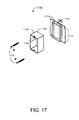
- FIG. 17 is an exploded perspective view of an adjustable plaster ring
- FIG. 18 is a perspective view of a junction box
- FIGS. 19A-D are top, perspective, front and side views, respectively, of a support arm.
- FIGS. 1A-B illustrate a pre-wired power distribution system 100 having an electrical box 120 configured to attach at least one power cable, an adjustable plaster ring 140 , an electrical device 160 mounted to the plaster ring 140 and a ground lanyard 180 pre-wired between the electrical device 160 and the electrical box 120 .
- the electrical box 160 can be any type known in the art.
- the electrical device 160 is a wiring module that is configured to connect to a source of electrical power via a plurality of cables (e.g., hot, neutral, and ground cables).
- the plurality of cables (not shown) are fed through the electrical box 120 and connected to a wiring portion of the wiring module, as disclosed herein.
- the wiring portion of the wiring module is substantially enclosed by the electrical box 120 and the adjustable plaster ring 140 , and is inaccessible to users.
- the wiring module also includes a user-accessible portion that removably accepts a functional module (not shown) that provides a selected electrical power distribution function.
- the functional module may be an outlet receptacle or a switch.
- the user-accessible portion of the wiring module includes shielded connectors, or sockets, that mate with the functional module.
- the shielded connectors help reduce the risk of electrical shock to users when a functional module is not installed in the wiring module.
- the shielded connectors are concealed by a protective cover 161 that protects the connectors from foreign objects, for example, during a rough-in phase of construction.
- the functional module can be installed without accessing the wiring portion of the wiring module or the power cables.
- the electrical device 160 (e.g., a wiring module) is mounted to the adjustable plaster ring 140 .
- the adjustable plaster ring provides for an adjustable distance between the electrical device 160 and the electrical box 120 .
- the adjustable plaster ring may include adjusting screws that can be turned to increase or decrease the distance between the electrical device 160 and the electrical box 120 . In this way, the depth of the electrical device 160 within a wall can be adjusted to result in the desired fit with the wallboard.
- the plaster ring 140 can be releasably attached to the electrical box 120 .
- the plaster ring 140 is movable between an open position FIG. 1A distal the electrical box 120 and a closed position FIG. 1B proximate the electrical box 120 .
- the plaster ring 140 can be releasably attached to the electrical box 120 in the closed position.
- the ground lanyard 180 provides a ground path from the electrical device 160 to the electrical box and mechanically supports the plaster ring in the open position. In some embodiments, however, the ground lanyard 180 does not necessarily support the plaster ring in the open position.
- the ground lanyard 180 is a ground wire connected between a single point ground 222 ( FIG. 2 ) on the electrical box 120 and a ground terminal 252 ( FIG. 2 ) on the electrical device 160 , as described in further detail with respect to FIGS. 2-3 , below.
- the ground lanyard 180 includes multiple ground wires connected between a ground bus bar 450 ( FIG. 4 ) mounted on a multi-gang electrical box 420 ( FIG. 4 ) and the ground terminals 462 ( FIG. 4 ) of multiple electrical devices 460 ( FIG. 4 ) mounted in a multi-gang plaster ring 440 ( FIG. 4 ), as described in further detail with respect to FIG. 4 , below.
- the electrical devices 160 may be wiring modules that are configured to accept various functional modules.
- the electrical box 120 is adapted to utilize various adjustable or fixed stud brackets, and the plaster ring 140 may be adjustable. These aspects facilitate the positioning of the mounted electrical devices during wall installation of the ground wire supporting wiring assembly 100 .
- a pre-wired power distribution system provides a broadly adaptable electrical system component.
- connections between the ground lanyard 180 and the electrical box 120 can be formed using any type of connection known in the art.
- a connection between the ground lanyard 180 and the electrical box 120 or the electrical device 160 may comprise an electrical screw terminal or a push-in connector.
- the electrical screw terminal is treated with a threadlocker material once the connection is made to improve the mechanical reliability of the connection.
- the ground lanyard 180 can also be soldered or clamped to the electrical box 120 or the electrical device 160 .
- the connection between the ground lanyard 180 and the electrical box 120 or the electrical device 160 can be made substantially permanent because the wiring module need not be removed to replace an outlet receptacle, switch, or other similar functional module.
- ground lanyard 180 and the electrical device 160 or the electrical box 120 can be made substantially permanent can also allow the connections to be made stronger (allowing the ground lanyard to support the weight of the electrical device 160 and adjustable plaster ring 140 , as described herein) and more reliable, both from a mechanical and an electrical standpoint.
- the pre-wired ground lanyard 180 can be advantageously tested at the manufacturer.
- the ground lanyard 180 is subjected to a mechanical pull test and an electrical continuity test.
- the pull-test has at least a 20 lb. force.
- the mechanical pull test and the electrical continuity test would otherwise be too cumbersome to perform on ground connections installed by an electrician at a worksite.
- these tests can be performed more efficiently than can be done at a worksite.
- these tests can be performed using equipment that is too expensive or bulky to use at a worksite where the ground connection might otherwise be installed.
- the ground lanyard 180 is not pre-wired but is instead configured to be connected upon installation of the electrical device 160 within the electrical box 120 .
- the plaster ring 140 can be supported in an open position ( FIG. 1A ) by the ground lanyard 180 , advantageously allowing an electrician hands-free access to one or more electrical devices 160 so as to wire these devices to power cables routed to the electrical box 120 .
- the plaster ring 140 is moved to a closed position ( FIG. 1B ) and secured to the electrical box 120 .
- Multiple electrical devices 160 can be pre-attached to the plaster ring 140 because doing so does not block access to the electrical box 120 or impede the wiring process.
- the use of a ground bus bar as the electrical box ground junction 184 advantageously allows the ground wiring of one or more power cables to the bus bar without resorting to ad hoc pigtail junctions or the use of the electrical device connectors.
- FIG. 2 illustrates a pre-wired power distribution system embodiment 200 having a wiring module 260 pre-wired with push-wire connectors 250 .
- a ground wire 280 extends between the wiring module 260 and an electrical box 120 .
- the ground wire 280 includes a push-wire connector at some point along its length to be connected to a ground cable fed into the electrical box 120 along with other power distribution cables.
- the ground wire 280 has a first end 282 attached to a ground push-wire connector 252 and a second end 284 secured to a ground attachment point 222 in the interior of the electrical box 120 .
- the ground attachment point 222 is a screw terminal.
- the push-wire connectors 250 are connected to internal crimp wires of the wiring module 260 and adapted to accept power and ground wires from cables (not shown) routed to the electrical box 120 .
- An electrician can easily and quickly attach the power wires to the appropriate push wire connectors 250 while the plaster ring 140 is supported by the ground wire 280 .
- FIG. 3 illustrates another pre-wired power distribution system embodiment 300 having a wiring module 360 with internal push-wire connectors 350 .
- a ground wire 280 extends between the wiring module 360 and an electrical box 120 .
- the ground wire 280 has a first end 282 attached to a ground push-wire connector 352 and a second end 284 secured to a ground attachment point 222 in the interior of the electrical box 120 .
- the push-wire connectors 350 are adapted to accept power and ground wires from cables (not shown) routed to the electrical box 120 .
- FIG. 4A is a front perspective view of an embodiment of a wiring module 460 having internal push-wire connectors 407 .
- the wiring module 460 has a mounting bracket 406 with an aperture 401 to mount the wiring module 460 to an adjustable plaster ring (e.g., 140 ) and an aperture 402 to attach a protective cover (e.g., 161 ) to the wiring module 460 .
- the wiring module 460 also includes shielded connectors 403 for receiving a functional module (e.g., an outlet receptacle functional module or a switch functional module).
- FIG. 4B is a rear perspective view of the wiring module 460 .
- the wiring module 460 includes a screw terminal ground lanyard connection point 452 .
- the ground lanyard connection point is, for example, an internal push-wire connector, a soldered joint, or a clamped joint.
- the wiring module 460 also includes internal push-wire connectors 407 for receiving power cables (e.g., hot, neutral, and ground power cables) routed to an electrical box (e.g., 120 ).
- the internal push-wire connectors 407 can also be used for creating a ground connection between the wiring module 460 and an electrical box (e.g., 120 ).
- the wiring module 460 could be mechanically and electrically coupled to an electrical box via a pre-wired ground lanyard (e.g., 180 ).
- the internal push-wire connectors 407 can be, for example, any type of push-in connector housed wholly or partially within the wiring module 460 for receiving power cables. In some embodiments, the internal push-wire connectors 407 are stab-in connectors.
- the wiring module 460 also includes a tab 405 that covers screw terminals that are in electrical contact with individual ones of the internal push-wire connectors 407 . The screw terminals can be used as an alternative to the internal push-wire connectors 407 if desired.
- the internal push-wire connectors 407 are particularly advantageous in situations where space within the electrical box 160 is limited or in any other setting where it is desirable to conserve space within the electrical box 160 . This may be true, for example, in relatively shallow walls (e.g., walls measuring less than about 3′′ from the outside edge of a wall stud to the back wall).
- the internal push-wire connectors 407 conserve space within the electrical box 160 (or allow for the usage of a shallower depth electrical box 160 ) because they do not include a length of wire between the wiring module and a connector as is the case for the embodiment illustrated in FIG. 2 having external push-wire connectors 250 . While such external push-wire connectors 250 are desirable under some circumstances, the internal push-wire connectors of FIGS.
- 3-4 can result in space and cost savings due to the elimination of wire joining the connectors (e.g., 250 ) to the wiring module (e.g., 260 ). It should be understood that the wiring module 460 with internal push-wire connectors can be used with or without a pre-wired ground lanyard (e.g., 180 ).
- FIG. 5 illustrates a pre-wired power distribution system embodiment 500 having a 3-gang electrical box 520 , a 3-gang adjustable plaster ring 540 , a ground bus bar 550 mounted directly to the electrical box 520 , three wiring modules 560 attached to the plaster ring 540 and a multiple wire ground lanyard 580 .
- the ground lanyard 580 extends between the bus bar 550 and ground terminals 562 on each of the wiring modules 560 .
- the bus bar 550 is configured to accept additional ground wires from power cables routed to and from the electrical box 520 .
- the ground lanyard 580 supports the plaster ring 540 in the open position shown, providing a wiring platform for the electrician to wire all three wiring modules 560 as a unit without having to handle and hold each of the wiring modules individually during the wiring process.
- the bus bar 550 is configured to allow the attachment of multiple ground wires 580 so as to provide ground connections for not only wiring modules, but also power cables routed in and out of the electrical box 520 .
- the bus bar 550 has a plurality of sections 552 and individual terminals 551 within each section. In an embodiment, there is one section 552 corresponding to each of the wiring modules 560 and multiple terminals 551 in each section. Each of the sections can be in electrical contact or electrically isolated. In this manner, ground wiring capacity increases with the size and electrical device mounting capacity of the electrical box 520 .
- Each terminal 551 is configured to accept a ground wire 580 from either a wiring module 560 or an attached power cable.
- the bus bar 550 has three sections corresponding to three wiring modules, and each section has four terminals configured to accept up to four ground wires, though other numbers of sections and terminals are also possible.
- the bus bar 550 advantageously eliminates the need for pigtail ground connections or the equivalent use of electrical device terminals.
- the bus bar 550 can be configured for use with external push wire connector wiring modules 260 ( FIG. 2 ), internal push wire connector wiring modules 360 ( FIG. 3 ) or any electrical devices having push-wire, screw terminal or similar wire connectors.
- a pre-wired power distribution system can be configured for any number of electrical devices, including 2-gang, 4-gang, and other many-gang embodiments.
- a pre-wired power distribution system has been disclosed in detail in connection with various embodiments. These embodiments are disclosed by way of examples only and are not to limit the scope of the claims that follow.
- One of ordinary skill in art will appreciate many variations and modifications.
- FIG. 6 illustrates a modular integrated wiring system 600 utilizing universal electrical wiring component embodiments 800 - 1100 .
- a floor bracket component 800 , a stud bracket component 900 , a box bracket component 1000 and an extended box bracket 1100 are included, providing adaptability for different electrical power distribution designs.
- Each wiring component 800 - 1100 provides mounting flexibility by adjusting to various wall dimensions, stud configurations, and electrical distribution point locations. Specifically, each component 800 - 1100 has an adjustable depth into the wall, guaranteeing a flush finish with the wall surface at every electrical distribution point.
- the floor bracket component 800 provides an adjustable height.
- the stud bracket component 900 can be positioned at any height and provides an adjustable distance between studs.
- the box bracket component 1000 can be positioned at any height, and the extended box bracket component 1100 can be positioned at any height and at various locations between studs. Further, each wiring component 800 - 1100 accommodates a variety of functional modules, including various outlets, switches, GFCI devices, and motion detectors to name few. Advantageously, the color of the functional modules and even some functionality can be readily changed at anytime without rewiring, as described below.
- the resulting modular integrated wiring system 600 has the labor saving advantages of prefabrication with the design and installation flexibility of individually configured and wired components.
- a universal electrical wiring component combining modular electrical devices and an adjustable, modular mount is described with respect to FIG. 7 , below.
- a floor bracket component 800 is described in further detail with respect to FIG. 8 , below.
- a stud bracket component 900 is described in further detail with respect to FIG. 9 , below.
- a box bracket component 900 is described in further detail with respect to FIG. 9 , below, and an extended box bracket component 1100 is described in further detail with respect to FIG. 11 , below.
- Adjustable mounts are described in detail with respect to FIGS. 12-16 , below.
- FIG. 7 further illustrates a universal electrical wiring component 700 having an adjustable mount 705 combined with a wiring module 701 .
- the adjustable mount 705 includes a bracket 707 and a box assembly 1200 .
- the bracket 707 can be, for example, a vertically adjustable floor bracket 1300 ( FIG. 13 ), a horizontally adjustable stud bracket 1400 ( FIG. 14 ), a box bracket 1500 ( FIG. 15 ), or an extended box bracket 1600 ( FIG. 16 ).
- the box assembly 1200 is mounted to the bracket 707 and the wiring module 701 is mounted in the box assembly 1200 .
- the wiring module 701 may be a regular wiring module 710 or a GFCI wiring module 720 .
- the adjustable mount 705 is configured to position the wiring module 701 at any of various locations within a building wall.
- the wiring module 701 is configured to connect to a source of electrical power and to removably accept a functional module 703 .
- the combination of adjustable mount and wiring module form a universal electrical wiring component that can implement a variety of electrical distribution points of an electrical system.
- a universal electrical wiring component can accept various outlet modules 750 - 760 and can be adjusted to implement a wall outlet.
- a universal electrical wiring component can accept various switch modules 740 and can be adjusted to implement a switch outlet.
- a universal electrical wiring component 200 may be, for example, a floor bracket component 800 ( FIG. 8 ), a stud bracket component 900 ( FIG. 9 ), a box bracket component 1000 ( FIG. 10 ) or an extended box bracket component 1100 ( FIG. 11 ).
- a cover 704 may be used to protect a wiring module 701 from damage prior to functional module installation.
- FIG. 8 illustrates a floor bracket component 800 having a wiring module 701 and an adjustable mount comprising a box assembly 1200 and a floor bracket 1300 .
- the floor bracket 1300 provides the wiring module 701 an adjustable height from the floor and the box assembly 1200 provides the wiring module 701 an adjustable distance from the box assembly 1200 for a flush position with a wall surface.
- FIG. 9 illustrates a stud bracket component 900 having a wiring module 701 and an adjustable mount comprising a box assembly 1200 and a stud bracket 1400 .
- the stud bracket 1400 provides the wiring module 701 an adjustable distance between studs and the box assembly 1200 provides the wiring module 701 an adjustable distance from the box assembly 1200 for a flush position with a wall surface.
- FIG. 10 illustrates a box bracket component 1000 having a wiring module 701 and an adjustable mount comprising a box assembly 1200 and a box bracket 1500 .
- the box bracket 1500 allows positioning of the wiring module 701 along a vertical stud.
- the box assembly 1200 provides the wiring module 701 an adjustable distance from the box assembly 1200 for a flush position with a wall surface.
- FIG. 11 illustrates an extended box bracket component 1100 having a wiring module 701 and an adjustable mount comprising a box assembly 1200 and an extended box bracket 1600 .
- the extended box bracket 1600 allows vertical positioning of the wiring module 701 along a stud and horizontal positioning between studs.
- the box assembly 1200 provides the wiring module 701 an adjustable distance from the box assembly 1200 for a flush position with a wall surface.
- FIG. 12 illustrates a box assembly 1200 having a junction box 1800 , an adjustable plaster ring 1700 and a support arm 1900 .
- the plaster ring 1700 removably attaches to the junction box 1800 and a wiring module 701 ( FIG. 7 ) attaches to the plaster ring 1700 .
- the plaster ring provides the wiring module 701 ( FIG. 7 ) with an adjustable distance from the junction box 1800 , as described in detail with respect to FIG. 17 .
- the junction box 1800 advantageously has an attached ground wire that can be quickly connected to a wiring module 701 ( FIG. 7 ).
- the plaster ring 1700 has slotted fastener apertures so that the plaster ring 1700 along with an attached wiring module can be removed from, and reattached to, the junction box 1800 by merely loosening and tightening, respectively, the fasteners.
- the support arm 1900 attaches to the back of the junction box to provide support against an inside wall surface, as described in further detail with respect to FIGS. 19A-D , below.
- FIG. 13 illustrates a floor bracket 1300 having an open front 1301 and ruled sides 1310 .
- the floor bracket 1300 has tabs 1320 for attaching the bracket 1300 to one or both of a floor joist or a wall stud.
- Side grooves 1330 allow fasteners to attach the junction box 1800 at an adjustable height from the floor.
- Conduit supports 1340 are adapted for attachment to conduits running to the junction box 1800 .
- the plaster ring 1700 is attached to the box 1800 through the open front 1301 so that the plaster ring 1700 can be removed from the box 1800 without removing the box 1800 from the bracket 1300 .
- FIG. 14 illustrates a stud bracket 1400 having a horizontal bar 1401 and ends 1403 .
- the ends 1403 are folded perpendicularly to the bar 1401 and adapted to secure the bracket 1400 horizontally between wall studs.
- the bar 1401 has grooves 1410 and a slot 1420 that extend horizontally to proximate both ends 1403 of the bracket 1400 .
- the grooves 1410 are adapted to slideably retain corresponding box tongues 1812 ( FIG. 18 ).
- the slot 1420 is centered between the grooves 1410 and accommodates a fastener that secures the junction box 1800 to the bracket 1400 while allowing the box to slideably adjust in position along the bar 1401 .
- the plaster ring 1700 is attached to the box 1800 and can be removed from the box 1800 without removing the box 1800 from the bracket 1400 .
- FIG. 15 illustrates a box bracket 1500 having a stud mounting face 1501 and a box mounting face 1503 .
- the stud mounting face 1501 is disposed perpendicular to the box mounting face 1503 and is adapted to fasten to a wall stud. Either side of the junction box 1800 attaches to the box mounting face 1503 .
- the box mounting face 1503 has a keyhole slots 1511 allowing the junction box 1800 to fasten and unfasten to the bracket 1500 without removing the fasteners 1520 .
- the stud mounting face 1501 has a plurality of mounting holes 1610 to accommodate fasteners that allow the junction box 1800 to be positioned along a stud.
- FIG. 16 illustrates an extended box bracket 1600 having an extended stud mounting face 1601 and a box mounting face 1603 .
- the box mounting face 1603 is disposed perpendicular to the extended stud mounting face 1601 and is adapted to fasten to the junction box 1800 .
- the extended stud mounting face 1601 is adapted to fasten to a wall stud.
- the extended stud mounting face 1601 has a plurality of mounting holes 1610 spaced along the length of the bracket 1600 to accommodate fasteners that allows the junction box 1800 to be position vertically along a stud and horizontally between studs.
- FIG. 17 further illustrates an adjustable plaster ring 1700 having a base ring 1710 , an insert ring 1720 and adjusting screws 1730 .
- the insert ring 1720 is slideably retained by the base ring 1710 and secured to the base ring 1710 by the adjusting screws 1730 .
- the insert ring 1720 is adapted to mount a wiring module and to adjust the wiring module position relative to the base ring 1710 in response to turning of the screws 1730 .
- the base ring 1710 has keyhole slots 1714 adapted to accommodate fasteners that attach the plaster ring 1700 to a junction box.
- the keyhole slot 1714 allows the plaster ring 1700 to fasten and unfasten to the Junction box without removing the fasteners.
- FIG. 18 further illustrates a junction box 1800 having a ground wire 1810 , a tongue 1812 and knockouts 1814 .
- the ground wire 1810 being pre-wired to the box, advantageously saves a fabrication step on the job site. Further, the ground wire 1810 is configured to insert into a push-wire connector on a pre-wired wiring module, providing a plug-in function module with a path to ground.
- the tongue 1812 stabilizes the box within a groove on a stud bracket, if used.
- the knockouts 1814 provide attachment points for power cable conduits.
- FIGS. 19A-D further illustrate a support arm 1900 adapted to attach to a back face of the junction box 1800 ( FIG. 18 ) and provide support against an inside wall surface.
- the support arm 1900 has an attachment section 1901 and a support section 1902 extending generally perpendicularly from one end of the attachment section 1901 .
- the attachment section is generally planar having an inside face 1904 that is disposed against the junction box 1800 and an opposite outside face 1905 that is disposed distal the junction box 1800 .
- the support section 1902 has a support face 1907 that is disposed against an inside wall surface.
- the attachment section 1901 has an adjustment slot 1910 , a fastener hole 1920 , and a plurality of bending slots 1930 distributed along and extending perpendicularly across the adjustment slot 1910 .
- the attachment section 1901 is configured to bend along one of the bending slots 1930 so as to provide a variable length support extending generally normal to the junction box back face.
- the support arm 1900 is held to the box 1800 with a fastener that is slideable along the adjustment slot 1910 , providing an adjustable support arm position.
Abstract
Description
Claims (16)
Priority Applications (5)
| Application Number | Priority Date | Filing Date | Title |
|---|---|---|---|
| US12/176,828 US7718893B2 (en) | 2006-07-29 | 2008-07-21 | Adjustable plaster ring cover |
| US12/778,886 US20100218969A1 (en) | 2006-07-29 | 2010-05-12 | Adjustable plaster ring cover |
| US13/405,042 US20120247803A1 (en) | 2006-07-29 | 2012-02-24 | Adjustable plaster ring cover |
| US14/219,643 US20140345933A1 (en) | 2006-07-29 | 2014-03-19 | Adjustable plaster ring cover |
| US14/630,319 US20150236490A1 (en) | 2006-07-29 | 2015-02-24 | Adjustable plaster ring cover |
Applications Claiming Priority (3)
| Application Number | Priority Date | Filing Date | Title |
|---|---|---|---|
| US83396606P | 2006-07-29 | 2006-07-29 | |
| US11/829,796 US20080053698A1 (en) | 2006-07-29 | 2007-07-27 | Pre-wired power distribution system |
| US12/176,828 US7718893B2 (en) | 2006-07-29 | 2008-07-21 | Adjustable plaster ring cover |
Related Parent Applications (1)
| Application Number | Title | Priority Date | Filing Date |
|---|---|---|---|
| US11/829,796 Continuation US20080053698A1 (en) | 2006-07-29 | 2007-07-27 | Pre-wired power distribution system |
Related Child Applications (1)
| Application Number | Title | Priority Date | Filing Date |
|---|---|---|---|
| US12/778,886 Continuation US20100218969A1 (en) | 2006-07-29 | 2010-05-12 | Adjustable plaster ring cover |
Publications (2)
| Publication Number | Publication Date |
|---|---|
| US20090020306A1 US20090020306A1 (en) | 2009-01-22 |
| US7718893B2 true US7718893B2 (en) | 2010-05-18 |
Family
ID=39149937
Family Applications (7)
| Application Number | Title | Priority Date | Filing Date |
|---|---|---|---|
| US11/829,796 Abandoned US20080053698A1 (en) | 2006-07-29 | 2007-07-27 | Pre-wired power distribution system |
| US12/176,828 Expired - Fee Related US7718893B2 (en) | 2006-07-29 | 2008-07-21 | Adjustable plaster ring cover |
| US12/176,980 Abandoned US20090021895A1 (en) | 2006-07-29 | 2008-07-21 | Adjustable plaster ring with attached clip |
| US12/778,886 Abandoned US20100218969A1 (en) | 2006-07-29 | 2010-05-12 | Adjustable plaster ring cover |
| US13/405,042 Abandoned US20120247803A1 (en) | 2006-07-29 | 2012-02-24 | Adjustable plaster ring cover |
| US14/219,643 Abandoned US20140345933A1 (en) | 2006-07-29 | 2014-03-19 | Adjustable plaster ring cover |
| US14/630,319 Abandoned US20150236490A1 (en) | 2006-07-29 | 2015-02-24 | Adjustable plaster ring cover |
Family Applications Before (1)
| Application Number | Title | Priority Date | Filing Date |
|---|---|---|---|
| US11/829,796 Abandoned US20080053698A1 (en) | 2006-07-29 | 2007-07-27 | Pre-wired power distribution system |
Family Applications After (5)
| Application Number | Title | Priority Date | Filing Date |
|---|---|---|---|
| US12/176,980 Abandoned US20090021895A1 (en) | 2006-07-29 | 2008-07-21 | Adjustable plaster ring with attached clip |
| US12/778,886 Abandoned US20100218969A1 (en) | 2006-07-29 | 2010-05-12 | Adjustable plaster ring cover |
| US13/405,042 Abandoned US20120247803A1 (en) | 2006-07-29 | 2012-02-24 | Adjustable plaster ring cover |
| US14/219,643 Abandoned US20140345933A1 (en) | 2006-07-29 | 2014-03-19 | Adjustable plaster ring cover |
| US14/630,319 Abandoned US20150236490A1 (en) | 2006-07-29 | 2015-02-24 | Adjustable plaster ring cover |
Country Status (1)
| Country | Link |
|---|---|
| US (7) | US20080053698A1 (en) |
Cited By (14)
| Publication number | Priority date | Publication date | Assignee | Title |
|---|---|---|---|---|
| US20110005800A1 (en) * | 2009-07-09 | 2011-01-13 | Thomas & Betts International, Inc. | Protective cover |
| US8028408B2 (en) | 2002-05-23 | 2011-10-04 | Protectconnect | Method of manufacturing a wiring module |
| US8105107B2 (en) | 2000-01-05 | 2012-01-31 | Protectconnect, Inc. | Safety electrical outlet and switch system |
| US8598454B2 (en) | 2011-12-15 | 2013-12-03 | Erico International Corporation | Electrical box with fitting flanges, and method of use |
| USRE45430E1 (en) | 2004-03-13 | 2015-03-24 | Protectconnect | Universal electrical wiring component |
| US9397491B2 (en) | 2012-10-15 | 2016-07-19 | Erico International Corporation | Electrical box mounting bracket with rails |
| US9627868B2 (en) | 2012-01-10 | 2017-04-18 | Erico International Corporation | Backless electrical box and method of making |
| US10742011B2 (en) | 2018-09-06 | 2020-08-11 | Eaton Intelligent Power Limited | Quick connect |
| US10971904B2 (en) | 2016-10-19 | 2021-04-06 | Southwire Company, Llc | Junction box with universal fitment articulating cover |
| US11005247B1 (en) | 2020-11-11 | 2021-05-11 | JPoint Innovation LLC | Junction box interface chassis and pluggable modular devices |
| US11050231B2 (en) | 2017-11-02 | 2021-06-29 | Panduit Corp. | Access ports for electrical enclosures |
| USD933020S1 (en) * | 2019-04-15 | 2021-10-12 | Marty Guthmiller | Flush mount electrical box assembly |
| US11557888B2 (en) | 2019-02-14 | 2023-01-17 | Erico International Corporation | Adjustable depth electrical wall mount ring |
| US11631969B2 (en) | 2019-04-15 | 2023-04-18 | Marty Guthmiller | Systems and methods for installing flush mounted electrical devices |
Families Citing this family (39)
| Publication number | Priority date | Publication date | Assignee | Title |
|---|---|---|---|---|
| US7780470B2 (en) | 2003-10-07 | 2010-08-24 | Pass & Seymour, Inc. | Plug tail lighting switch and control system |
| US20080053698A1 (en) * | 2006-07-29 | 2008-03-06 | Steve Purves | Pre-wired power distribution system |
| US20090065248A1 (en) * | 2007-09-07 | 2009-03-12 | Bill Finley | Devices, systems, and/or methods for electrically coupling an electric motor |
| US7847200B2 (en) * | 2006-09-07 | 2010-12-07 | Siemens Industry, Inc. | Devices, systems, and/or methods for electrically coupling a high voltage electric motor |
| US8072736B2 (en) * | 2008-07-28 | 2011-12-06 | Tyco Electronics Brasil Ltda | Movable electrical power distribution assembly |
| US9398717B2 (en) | 2009-05-29 | 2016-07-19 | Rosendin Electric, Inc. | Modular power skid assembled with different electrical cabinets and components mounted on the skid |
| US8681479B2 (en) | 2009-05-29 | 2014-03-25 | Rosendin Electric, Inc. | Various methods and apparatuses for an integrated power distribution platform |
| US9819167B2 (en) | 2009-09-04 | 2017-11-14 | Cantex, Inc. | Electrical accessories and associated methods of use and manufacture |
| DE102009047435A1 (en) * | 2009-12-03 | 2011-06-09 | Robert Bosch Gmbh | Method for generating control signals |
| CA2752301C (en) | 2010-09-14 | 2019-09-03 | Southwire Company | Folded electrical junction boxes and associated methods of use and manufacture |
| US8658894B1 (en) | 2010-09-14 | 2014-02-25 | Cooper Technologies Company | Cover assembly for an electrical box |
| CA2752303C (en) | 2010-09-14 | 2019-09-03 | Southwire Company | Electrical accessories and associated methods of use and manufacture |
| US20120181055A1 (en) * | 2011-01-13 | 2012-07-19 | Mr. William Harrison Holton, III | High Volume Cover |
| US8833013B2 (en) * | 2011-08-18 | 2014-09-16 | Rodney James Harman | Termination collar for air duct |
| WO2013177117A1 (en) * | 2012-05-22 | 2013-11-28 | Erico International Corporation | Electrical box |
| FR3000312B1 (en) * | 2012-12-20 | 2017-02-03 | Legrand France | ELECTRICAL BOX FOR ELECTRICAL EQUIPMENT |
| US10080301B2 (en) * | 2013-10-17 | 2018-09-18 | Cree, Inc. | High voltage power chip module |
| US9431798B2 (en) | 2014-09-17 | 2016-08-30 | Rosendin Electric, Inc. | Various methods and apparatuses for a low profile integrated power distribution platform |
| US10256614B2 (en) | 2014-12-16 | 2019-04-09 | Hubbell Incorporated | Adjustable mud ring assemblies |
| US9793697B1 (en) * | 2015-04-15 | 2017-10-17 | Michael Colao | Junction box and plug-ins |
| US10862285B2 (en) | 2015-09-01 | 2020-12-08 | Chad Fisher | Electrical junction box cover and related assemblies and methods for completing electrical installations |
| US9839146B2 (en) | 2015-10-20 | 2017-12-05 | Cree, Inc. | High voltage power module |
| US10120678B2 (en) * | 2016-11-15 | 2018-11-06 | Dell Products, L.P. | Firmware update control mechanism using organizational groups |
| US10263403B2 (en) | 2017-02-17 | 2019-04-16 | Hubbell Incorporated | Adjustable mud ring assembly |
| US10461482B1 (en) | 2017-06-06 | 2019-10-29 | Robert Perry | Electrically-charged outlet |
| US10622770B2 (en) * | 2017-07-24 | 2020-04-14 | Sapient Industries, Inc. | Custom power outlet socket with integrated wireless functionality |
| US10955096B1 (en) * | 2018-01-23 | 2021-03-23 | The Light Source, Inc. | Electrical connector pipe adapted for structural applications |
| US20190386420A1 (en) * | 2018-06-18 | 2019-12-19 | Monty McDonald | Coaxial Cable Protector |
| US10994966B2 (en) * | 2018-06-25 | 2021-05-04 | Otis Elevator Company | Fixture plate and housing |
| USD908632S1 (en) | 2018-09-17 | 2021-01-26 | Cree Fayetteville, Inc. | Power module |
| JP6820303B2 (en) * | 2018-10-29 | 2021-01-27 | 矢崎総業株式会社 | Electrical junction box and its ground connection structure |
| CN109524805A (en) * | 2018-12-07 | 2019-03-26 | 国家电网公司 | A kind of antidetonation terminal block convenient for being isolated and being shorted ground connection |
| US10777984B1 (en) * | 2019-06-03 | 2020-09-15 | Richard M. Elbert | Pre-wired junction box with quick-connect clip electrical wire connectors |
| USD938920S1 (en) * | 2020-01-15 | 2021-12-21 | BookerLab, LLC | Power and audio adapter box |
| US11915675B2 (en) * | 2020-01-15 | 2024-02-27 | BookerLab, LLC | Communications system, retrofit cabling kit, and retrofit connector interface |
| USD947788S1 (en) * | 2020-01-15 | 2022-04-05 | BookerLab, LLC | Power and audio adapter box |
| USD957348S1 (en) * | 2020-06-17 | 2022-07-12 | Comemso GmbH | Electric outlet |
| CA3123898A1 (en) | 2020-07-06 | 2022-01-06 | Hubbell Incorporated | Multi-gang adjustable mud ring assemblies |
| CN112217165A (en) * | 2020-08-25 | 2021-01-12 | 衡阳和众信息技术有限责任公司 | Junction box for network engineering |
Citations (199)
| Publication number | Priority date | Publication date | Assignee | Title |
|---|---|---|---|---|
| US723866A (en) | 1902-07-19 | 1903-03-31 | Hart Mfg Co | Electric switch. |
| US776855A (en) | 1904-07-30 | 1904-12-06 | Hart Mfg Co | Electric switch. |
| US949123A (en) | 1907-07-25 | 1910-02-15 | Ida S Rosenheim | Electric switch. |
| US1171914A (en) | 1906-08-13 | 1916-02-15 | Gen Electric | Receptacle and plug. |
| US1328224A (en) | 1915-04-01 | 1920-01-13 | Benjamin Electric Mfg Co | Receptacle |
| US2163201A (en) | 1936-03-13 | 1939-06-20 | Kalencik Paul | Analyzer plug |
| US2189251A (en) | 1938-08-16 | 1940-02-06 | Gordon W Potter | Plug connector |
| US2433917A (en) | 1944-07-15 | 1948-01-06 | Mccartney William James | Outlet box and plug-in connections therefor |
| US2447597A (en) | 1945-08-28 | 1948-08-24 | Charles H Reed | Self-locking electric outlet and plug |
| US2477803A (en) | 1946-06-25 | 1949-08-02 | Clarence A Huber | Electrical outlet safety device |
| US2524701A (en) | 1949-08-03 | 1950-10-03 | Charles T Grill | Combination electric plug and socket |
| US2908743A (en) | 1956-11-30 | 1959-10-13 | Robert T Premoshis | Electrical outlet |
| US2969518A (en) | 1959-11-12 | 1961-01-24 | Saul I Slater | Duplex plug receptacle |
| US3189077A (en) | 1962-08-07 | 1965-06-15 | Jr Julian G Willis | Retaining clip for headed fasteners |
| US3214726A (en) | 1962-04-27 | 1965-10-26 | Axial S A | Novel safety plug and receptacle for low-tension installations |
| US3317881A (en) | 1966-04-18 | 1967-05-02 | John C Setecka | Safety device for electrical receptacles |
| US3467941A (en) | 1966-11-03 | 1969-09-16 | Gen Electric | Duplex socket contact with breakoff tab |
| US3489985A (en) | 1967-10-30 | 1970-01-13 | Gen Electric | Contiguous cam contact for convenience outlet |
| US3510822A (en) | 1967-08-03 | 1970-05-05 | Edmund M Patterson | Electrical connectors |
| US3588786A (en) | 1969-11-10 | 1971-06-28 | Joseph A Alfiero | Connector for terminal strips |
| US3609647A (en) | 1968-12-19 | 1971-09-28 | Angelo Castellano | Electrical receptacle |
| US3654663A (en) | 1968-03-06 | 1972-04-11 | Elektroverken I Gavle Ab | Device for closure of boxes, preferentially boxes for enclosure of electrical equipment |
| US3710287A (en) | 1971-07-01 | 1973-01-09 | W Eckert | Insulated plug |
| US3732524A (en) | 1970-11-25 | 1973-05-08 | Woodhead Inc Daniel | Electrical receptacle with safety cover |
| US3868161A (en) | 1973-10-01 | 1975-02-25 | Amp Inc | Electrical component |
| US3879101A (en) | 1973-12-04 | 1975-04-22 | George T Mckissic | Electric Plug-In Module |
| US3930704A (en) | 1973-06-20 | 1976-01-06 | Dinko Dekanic | Wall socket |
| US3972498A (en) | 1975-07-30 | 1976-08-03 | Eaton Corporation | Device for attaching electrical boxes to metal studs |
| US4103125A (en) | 1977-04-15 | 1978-07-25 | Louis Marrero | Modular electrical switch/outlet assembly |
| US4105884A (en) | 1977-04-04 | 1978-08-08 | Damsky Arnold M | Electrical toggle switch lever extender |
| US4117258A (en) | 1976-05-21 | 1978-09-26 | Benjamin Shanker | Modular electric light switch assembly |
| US4148536A (en) | 1976-11-22 | 1979-04-10 | Petropoulsos Nikolaostzakos J | Safety electrical receptacle |
| US4165443A (en) | 1975-07-24 | 1979-08-21 | Figart Earl C | Power distribution system |
| US4166934A (en) | 1978-08-15 | 1979-09-04 | Louis Marrero | Modular electrical switch/outlet assembly |
| US4179175A (en) | 1978-10-02 | 1979-12-18 | Farnworth Ivan A | Safety socket |
| US4196521A (en) | 1978-09-15 | 1980-04-08 | Continental Scale Corporation | Height measuring device |
| US4230386A (en) | 1979-01-12 | 1980-10-28 | Farnworth Ivan A | Self locking safety socket |
| US4263472A (en) | 1979-05-23 | 1981-04-21 | Maheu Joseph S | Electrical box |
| US4343411A (en) | 1981-03-02 | 1982-08-10 | Chesnut Ronald D | Electrical box cover |
| US4372634A (en) | 1981-03-04 | 1983-02-08 | Amp Incorporated | Tilt latch zero insertion force connector assembly |
| US4403824A (en) | 1981-03-02 | 1983-09-13 | The Scott & Fetzer Company | Plug connector and receptacle |
| US4427864A (en) | 1979-07-30 | 1984-01-24 | Oster Stanley M | Electrical outlet switch |
| US4445739A (en) | 1982-05-04 | 1984-05-01 | Wooten Norman W | Male plug with automatic prong cover |
| US4485282A (en) | 1983-01-28 | 1984-11-27 | Lee Long River | Plug-in type of safety wall switch and wall outlet |
| US4493517A (en) | 1980-12-03 | 1985-01-15 | Wkr Limited | Electrical socket connector |
| US4599485A (en) | 1984-12-21 | 1986-07-08 | Smolik Robert A | Electrical receptacle box assembly |
| US4600258A (en) | 1985-07-23 | 1986-07-15 | Andrew Hu | Security socket |
| US4605270A (en) | 1985-01-22 | 1986-08-12 | Nejdeh Aslizadeh | Cover for electrical outlet |
| US4607906A (en) | 1984-12-24 | 1986-08-26 | Eagle Electric Mfg. Co., Inc. | Panel-mounted duplex electrical receptacle and power terminal strip |
| US4612412A (en) | 1984-08-02 | 1986-09-16 | Brand-Rex Company | Electrical outlet box assembly |
| US4617613A (en) | 1985-01-22 | 1986-10-14 | Rice Keith Q | Illuminated electrical outlet cover plate |
| US4626052A (en) | 1984-02-08 | 1986-12-02 | Rumble Clive S | Electrical connectors |
| US4627675A (en) | 1983-08-04 | 1986-12-09 | Taylor Richard D | Wiring system with quick connect wire terminals |
| US4634015A (en) | 1985-07-15 | 1987-01-06 | Taylor Jerald M | Adjustable electric outlet box |
| US4640564A (en) | 1986-03-04 | 1987-02-03 | Hill Joe W | Electrical outlet faceplate with locking closures |
| US4645089A (en) | 1981-09-14 | 1987-02-24 | Martha Willene Horsley | Adjustable outlet box mounting |
| US4664457A (en) | 1986-01-08 | 1987-05-12 | Suchy Leonard J | Outlet assembly for built in vacuum systems |
| US4722693A (en) | 1987-03-30 | 1988-02-02 | Friedhelm Rose | Safety shutters for electrical receptacles |
| US4747506A (en) | 1987-02-06 | 1988-05-31 | Stuchlik Iii Charles F | Adjustable outlet box mounting assembly |
| US4750890A (en) | 1987-06-18 | 1988-06-14 | The J. M. Ney Company | Test socket for an integrated circuit package |
| US4780088A (en) | 1987-08-17 | 1988-10-25 | Means Eugene E | Connecting plug for electrical switches and receptacles |
| US4784614A (en) | 1987-09-30 | 1988-11-15 | Thomas & Betts Corporation | Components having means for keyed interconnectability |
| US4798916A (en) | 1987-08-28 | 1989-01-17 | Engel Stephen M | Safety plate for electrical outlet |
| US4808127A (en) | 1985-10-18 | 1989-02-28 | Arbus, Inc. | Connector assembly |
| US4842551A (en) | 1986-07-11 | 1989-06-27 | Heimann Anthony J | Modular connector assembly for electrical utility box |
| US4871893A (en) | 1988-07-29 | 1989-10-03 | Lightolier, Inc. | Slide control switch |
| US4873469A (en) | 1987-05-21 | 1989-10-10 | Pittway Corporation | Infrared actuated control switch assembly |
| US4880950A (en) | 1988-02-23 | 1989-11-14 | Lightolier, Inc. | Control switch |
| US4914265A (en) | 1988-08-03 | 1990-04-03 | Nicolet Plastique Ltee | Exterior cover for an electrical socket or switch |
| USD308045S (en) | 1987-05-06 | 1990-05-22 | Prescolite Inc. | Combined face plate and control operators for an electrical switch or similar articles |
| US4952164A (en) | 1989-08-16 | 1990-08-28 | Amp Incorporated | Plug-in outlet unit for modular furniture power distribution system |
| USD310814S (en) | 1988-08-11 | 1990-09-25 | Leviton Manufacturing Co., Inc. | Combined sound activated switch and cover plate |
| US4967990A (en) | 1989-01-26 | 1990-11-06 | B-Line Systems, Inc. | Support for an electrical box |
| US4972045A (en) | 1989-01-17 | 1990-11-20 | Groupe Sodepro Inc. | Electrical switch plate cover |
| US4988840A (en) | 1988-02-23 | 1991-01-29 | Lightolier, Inc. | Control switch |
| USD316250S (en) | 1988-03-28 | 1991-04-16 | Nicolet Plastique Ltd. | Combined wall plate and switch |
| US5012043A (en) | 1989-02-21 | 1991-04-30 | Seymour Michael R | Adjustable outlet box assembly and method of application |
| US5030119A (en) | 1989-09-27 | 1991-07-09 | Safe Care Products, Inc. | Safety plug |
| US5042673A (en) | 1989-06-22 | 1991-08-27 | Mcshane William J | Electric box extension |
| US5092787A (en) | 1989-08-16 | 1992-03-03 | Amp Incorporated | Power distribution for modular furniture units |
| US5098046A (en) | 1987-11-09 | 1992-03-24 | Webb Ronald D | Electrical junction box mounting bracket device and method |
| US5178555A (en) | 1991-10-02 | 1993-01-12 | Amp Incorporated | Installation of junction boxes along a raceway |
| US5209444A (en) | 1989-01-26 | 1993-05-11 | B-Line Systems, Inc. | Support for an electrical box |
| US5245507A (en) | 1992-04-17 | 1993-09-14 | Pro-Mark, Inc. | Weather resistant container for timer components of an irrigation system |
| USD341125S (en) | 1990-07-30 | 1993-11-09 | Building Technology Associates | Interfacing portion of an electrical connector |
| US5289934A (en) | 1993-09-02 | 1994-03-01 | Smith Benjamin H | Adjustable mounting assembly for electrical outlet box |
| US5293097A (en) | 1990-11-29 | 1994-03-08 | Novitas, Inc. | Fully automatic energy efficient lighting control and method of making same |
| US5297973A (en) | 1992-09-15 | 1994-03-29 | Gorman Michael P | Safety electrical connection apparatus |
| US5330137A (en) | 1993-01-04 | 1994-07-19 | Oliva John H | Apparatus and method for mounting an electrical box between studs in a wall |
| US5342993A (en) | 1993-01-04 | 1994-08-30 | Siems Steven L | Weather-proof floor outlet and method |
| US5386959A (en) | 1988-12-14 | 1995-02-07 | Erico International Corporation | Box support |
| US5397929A (en) | 1989-01-19 | 1995-03-14 | Building Technology Associates | Integrated outlet for communications and electrical power |
| US5399806A (en) | 1992-02-21 | 1995-03-21 | Olson; Richard A. | Modular electrical wiring system |
| US5415564A (en) | 1992-09-14 | 1995-05-16 | Winter; Craig | Junction box for quick release mounting of electrical circuit components |
| US5448011A (en) | 1993-04-08 | 1995-09-05 | Erico International Corporation | Low voltage mounting plate and method of installation |
| US5466164A (en) | 1993-03-09 | 1995-11-14 | Sumitomo Wiring Systems, Ltd. | Connector having a protective hood |
| US5486121A (en) | 1994-07-07 | 1996-01-23 | The Whitaker Corporation | Electrical connector assembly |
| US5488121A (en) | 1994-10-31 | 1996-01-30 | Siltech Inc. | Di-guerbet esters |
| US5500487A (en) | 1993-10-12 | 1996-03-19 | Commonwealth Of Puerto Rico | Modular pull-out assembly |
| US5516068A (en) | 1992-07-31 | 1996-05-14 | Rice; Frank | Device support bracket |
| US5526952A (en) * | 1995-03-20 | 1996-06-18 | Green; Robert L. | Protective covers for electrical outlet boxes |
| US5551884A (en) | 1995-01-25 | 1996-09-03 | Burkhart, Sr.; Steven A. | Locking electrical outlet |
| US5608196A (en) | 1995-09-08 | 1997-03-04 | The Whitaker Corporation | Normally closed dimmer switch contact assembly separated by rocker actuator interposed insulation plate |
| US5611701A (en) | 1994-02-24 | 1997-03-18 | Asian Micro Sources, Inc. | Collapsible prong plug device for battery charger |
| US5613874A (en) | 1995-05-05 | 1997-03-25 | Ortronics Inc. | Snap-in designation strip for modular information management oulet |
| US5625531A (en) | 1995-10-25 | 1997-04-29 | General Electric Company | Motor control center pilot devices bracket |
| US5639991A (en) | 1995-02-28 | 1997-06-17 | Schuette; Gail D. | Utility box insert |
| USD380452S (en) | 1995-07-13 | 1997-07-01 | The Watt Stopper | Wall-mounted switch |
| USD384643S (en) | 1995-11-14 | 1997-10-07 | Nellcor Puritan Bennett Incorporated | Sensor connector |
| US5730617A (en) | 1993-11-10 | 1998-03-24 | Yazaki Corporation | Guide structure for an electronic unit |
| US5741153A (en) | 1995-07-27 | 1998-04-21 | Ortronics, Inc. | Modular connectors including terminated rear connector designation for insulation displacement connectors |
| US5773757A (en) | 1996-08-12 | 1998-06-30 | Pembroke Properties, Inc. | Retractable electrical power cord apparatus |
| US5775935A (en) | 1996-12-18 | 1998-07-07 | Computer Data Exchange, Inc. | System and method for connecting color coded cables to a device |
| US5786551A (en) | 1995-11-30 | 1998-07-28 | Otis Elevator Company | Closed loop fuzzy logic controller for elevator dispatching |
| US5785551A (en) | 1995-03-28 | 1998-07-28 | Libby; Robert A. | Quick connect electrical box |
| US5807139A (en) | 1994-11-04 | 1998-09-15 | The Siemon Company | Surface mount multimedia outlet |
| USD399495S (en) | 1997-06-24 | 1998-10-13 | Bp Holdings, Llc | Switch plate with voice recorder |
| US5885088A (en) | 1997-07-14 | 1999-03-23 | Molex Incorporated | Electrical connector assembly with polarization means |
| US5906497A (en) | 1997-12-12 | 1999-05-25 | Hewlett Packard Company | Processor retention frame and extraction device |
| US5925850A (en) | 1997-09-05 | 1999-07-20 | Park; Mike K. | Electrical outlet, switch and junction boxs |
| US5931325A (en) | 1998-02-20 | 1999-08-03 | Filipov; Stefan Dimitrov | Adjustable mudring for conventional electrical outlet box |
| US5967354A (en) | 1998-06-30 | 1999-10-19 | Thomas & Betts International, Inc. | Fully adjustable electrical receptacle housing |
| USD415472S (en) | 1998-05-05 | 1999-10-19 | Francis Fredrick Kelso | Toggle/dimmer switch plate |
| US5980279A (en) | 1997-09-25 | 1999-11-09 | Nienkamper Furniture & Accessories Inc. | Recessed electrical receptacle and work surface |
| US5998747A (en) | 1998-05-05 | 1999-12-07 | Kelso; Francis Fredrick | Switch plate assembly |
| US6029581A (en) | 1998-04-23 | 2000-02-29 | Lucent Technologies, Inc. | Pivotable work table |
| US6036516A (en) | 1995-12-11 | 2000-03-14 | Byrne; Norman R. | Electrical interconnection assembly with additional outlet receptacles |
| CN2381040Y (en) | 1999-06-30 | 2000-05-31 | 刘志军 | Multipurpose safety power-supply connection device |
| US6098939A (en) | 1999-01-11 | 2000-08-08 | He; Ping | Electrical junction box supporting bracket |
| USD430114S (en) | 1998-10-01 | 2000-08-29 | Bp Holdings, Llc. | Switch plate with voice recorder |
| US6201187B1 (en) | 1999-10-01 | 2001-03-13 | Theodore B. Burbine | Pre-wired universal junction block |
| US6209836B1 (en) | 1996-09-27 | 2001-04-03 | Hubbell Incorporated | Electrical box mounting bracket |
| US6231358B1 (en) | 2000-01-06 | 2001-05-15 | Angelo Fan Brace Licensing, L.L.C. | Electrical plug and receptacle having safety features |
| US6259351B1 (en) | 1999-10-01 | 2001-07-10 | Pass & Seymour, Inc. | Toggle and slide dimmer switch |
| US6309248B1 (en) | 2000-01-27 | 2001-10-30 | Leviton Manufacturing Co., Inc. | Modular GFCI receptacle |
| US6311229B1 (en) | 1996-06-04 | 2001-10-30 | Elsag International N.V. | Color coding identification system for a block I/O system |
| US6341981B1 (en) | 2000-01-05 | 2002-01-29 | Michael P. Gorman | Safety electrical outlet and switch system |
| US6371790B1 (en) | 2000-12-21 | 2002-04-16 | Hon Hai Precision Ind. Co., Ltd. | Electrical assembly having anti-mismating device |
| US6392140B1 (en) | 2000-04-28 | 2002-05-21 | General Electric Company | Hinged pilot device door and bracket assembly |
| USD461775S1 (en) | 2001-04-12 | 2002-08-20 | Lyall Assemblies, Inc. | Switch adapter |
| US6441304B1 (en) | 2000-05-05 | 2002-08-27 | The Wiremold Company | Electrical outlet assembly |
| US6461189B1 (en) | 2000-12-21 | 2002-10-08 | Compaq Information Technologies Group, L.P. | Connector map |
| US6465735B2 (en) | 1998-02-24 | 2002-10-15 | Lindy Lawrence May | Modular electrical system |
| US6484979B1 (en) | 2000-07-21 | 2002-11-26 | Lewis B. Medlin, Jr. | Adjustable electrical box support |
| US6485336B1 (en) | 1999-01-25 | 2002-11-26 | Weidmuller Interface Gmbh & Co. | Coded electrical device and method |
| US6492591B1 (en) | 2001-06-11 | 2002-12-10 | Kimball International, Inc. | Movable electrical and data services module |
| US20020185296A1 (en) | 2000-01-07 | 2002-12-12 | Schultz James Douglas | Prewired electrical apparatus having quick connect components |
| US6530806B2 (en) | 2000-10-19 | 2003-03-11 | Eric L. Nelson | Electrical outlet fixture recessible in a housing |
| USD472883S1 (en) | 2001-09-10 | 2003-04-08 | Delta Systems, Inc. | Terminal configuration of a three pole plunger switch |
| US6590155B2 (en) | 2001-04-25 | 2003-07-08 | Paul A. Vrame | Floor stand for mounting electrical box and for supporting conduit |
| US6623296B2 (en) | 2001-05-09 | 2003-09-23 | Nichido Kogyo Kabushiki Kaisha | Plug socket |
| US20030178218A1 (en) | 2002-03-22 | 2003-09-25 | Taymac Corporation | Outlet cover |
| US20030189043A1 (en) | 2002-04-04 | 2003-10-09 | Wegner Wesley Gene | Electrical box extension |
| US6642450B1 (en) | 2002-12-06 | 2003-11-04 | Feng-Shen Hsiao | Wall outlet assembly |
| US20030205654A1 (en) | 2002-05-03 | 2003-11-06 | Randy Petak | Universal electrical outlet box mounting bracket |
| US6648678B1 (en) | 1999-08-10 | 2003-11-18 | Yazaki Corporation | Structure of rotatably mounting an electronic unit on an electrical connection box in a removable manner |
| US20030213801A1 (en) * | 2002-05-14 | 2003-11-20 | Bradley Frank H. | Cover plate for electrical box |
| US6653566B2 (en) | 2002-01-28 | 2003-11-25 | Pw Industries, Inc. | Covers for outlet boxes |
| US6686540B2 (en) | 2000-06-08 | 2004-02-03 | Carlo Compagnone, Jr. | Temporary protective cover for an electrical box |
| US6700062B1 (en) | 2003-01-10 | 2004-03-02 | Philip Brown Allen, Jr. | Device for providing access to electrical connections to enclosure |
| US20040048507A1 (en) | 2002-03-05 | 2004-03-11 | George Hage | Quick-release sensor assembly and method |
| US6718674B2 (en) | 2002-03-21 | 2004-04-13 | Panduit Corp. | Apparatus and system for identification labeling |
| US6730845B1 (en) | 2000-05-18 | 2004-05-04 | General Electric Company | Electric component box with removable cover |
| US6747206B1 (en) | 2002-12-03 | 2004-06-08 | Genlyte Thomas Group Llc | Junction box and ballast module assembly |
| US20040129444A1 (en) | 2002-11-01 | 2004-07-08 | Adams Jason O. | Receptacle and plug therefor |
| US6765146B1 (en) | 2003-03-14 | 2004-07-20 | Fabworks, Llc | Adjustable floor bracket article and method |
| US6770814B2 (en) | 1999-12-06 | 2004-08-03 | Michael Shotey | Base for electrical outlet and related method |
| US6774307B2 (en) | 2002-05-07 | 2004-08-10 | Applied Technology And Solutions | Through-wall electrical system |
| US6803521B2 (en) | 2001-04-25 | 2004-10-12 | Illini Electrical Sales, Inc. | Floor stand having parallel uprights of adjustable lengths, for electrical box having plaster ring |
| US6805567B2 (en) | 2002-08-06 | 2004-10-19 | Pent Products, Inc. | Power distribution system |
| US6820760B2 (en) | 2002-04-04 | 2004-11-23 | Wesley Gene Wegner | Electrical box extension |
| US6830477B2 (en) | 2001-10-19 | 2004-12-14 | Pulizzi Engineering Inc. | Nema-type AC power outlet connectors |
| US20050001123A1 (en) | 2003-01-22 | 2005-01-06 | Cheatham James F. | Electrical box mounting brackets |
| US6840785B2 (en) | 2003-03-07 | 2005-01-11 | Thomas & Betts International, Inc. | Cover assembly for an electrical box |
| US6843680B2 (en) | 2002-05-23 | 2005-01-18 | Protectconnect | Electrical distribution terminal guard |
| US6850159B1 (en) | 2001-05-15 | 2005-02-01 | Brian P. Platner | Self-powered long-life occupancy sensors and sensor circuits |
| US6867370B2 (en) | 2000-06-08 | 2005-03-15 | Carlo Compagnone, Jr. | Temporary protective cover for an electrical box |
| US20050067180A1 (en) | 2003-09-29 | 2005-03-31 | Cong Dinh | Combination mounting bracket and adapter plate for mounting electrical boxes |
| US6875922B1 (en) * | 2004-04-22 | 2005-04-05 | Pw Industries, Inc. | Position adjustable outlet box system |
| US6906260B2 (en) | 2003-03-24 | 2005-06-14 | Mark S. Grendahl | Protective cover plate |
| US6908334B2 (en) | 2003-07-02 | 2005-06-21 | Pei-Chin Huang | Interlining panel structure for multiple socket |
| US6923663B2 (en) | 2002-09-17 | 2005-08-02 | Leviton Manufacturing Co., Inc. | Triplex receptacle |
| US6925850B2 (en) | 2000-05-31 | 2005-08-09 | Magus Gmbh | Method and device for calibrating rotary axis |
| US20050176278A1 (en) | 2003-12-31 | 2005-08-11 | Cheatham James F. | Sliding clip electrical connection box mounting bracket |
| US6956169B1 (en) | 2004-03-17 | 2005-10-18 | Taymac Corporation | Flush-mount in-use cover for electrical outlet |
| US6967284B1 (en) | 2004-09-20 | 2005-11-22 | Arlington Industries, Inc. | Electrical box mounting assembly |
| US6986676B1 (en) | 2004-07-29 | 2006-01-17 | James Tronolone | Multi-channel high definition video interconnect |
| US20060021780A1 (en) | 2004-08-02 | 2006-02-02 | Hill Douglas C | Temporary outlet cover |
| US20060065510A1 (en) | 2004-09-03 | 2006-03-30 | Kiko Frederick J | Universal control apparatus and methods |
| US7071414B2 (en) | 2004-01-16 | 2006-07-04 | Kim Kyung T | Cover plate for electrical outlets and switches |
| US7083466B1 (en) | 2005-05-06 | 2006-08-01 | Wayming Hwang | Cover of wiring box for use in telecommunication line |
| US7273392B2 (en) | 2004-07-29 | 2007-09-25 | Dan Fields | Universal electrical module |
| US7312396B1 (en) | 2004-03-13 | 2007-12-25 | Protectconnect, Inc. | Universal electrical wiring component |
| US7323638B1 (en) | 2006-09-13 | 2008-01-29 | Pass & Seymour, Inc. | Wall box receptacle with modular plug-in device |
| US7357652B1 (en) | 2006-10-27 | 2008-04-15 | Leviton Manufacturing Company, Inc. | Modular wiring system with locking elements |
| US7390965B2 (en) * | 2005-11-17 | 2008-06-24 | Daniel Hartwig | Temporary covers for electrical boxes |
| US7442874B2 (en) * | 2000-06-08 | 2008-10-28 | Compagnone Jr Carlo | Temporary protective cover for an electrical box |
| US7468486B2 (en) * | 2006-08-10 | 2008-12-23 | Frank Shaochong Yan | Adjustable mud ring system |
| US7495170B2 (en) * | 2006-06-16 | 2009-02-24 | Thomas & Betts International, Inc. | Adjustable device cover |
Family Cites Families (23)
| Publication number | Priority date | Publication date | Assignee | Title |
|---|---|---|---|---|
| US1758126A (en) * | 1925-04-16 | 1930-05-13 | Peterson Abdel John | Outlet locator |
| US1956196A (en) * | 1931-04-25 | 1934-04-24 | Harry E Korab | Shield for outlet boxes |
| US2397688A (en) * | 1944-04-12 | 1946-04-02 | Stephen B Osinski | Electric outlet box |
| US3087984A (en) * | 1957-08-19 | 1963-04-30 | Waranch Myer | Wiring ficture and forming board |
| US3716651A (en) * | 1971-07-14 | 1973-02-13 | A Werner | Minimum wire box and device adapters |
| GB2156985B (en) * | 1984-04-02 | 1987-06-24 | Teltec Electronic Equip | Apparatus for measuring movable part-structures, eg blood vessels, within a living body |
| JPS6135571A (en) * | 1984-07-27 | 1986-02-20 | Hitachi Ltd | Photoelectric transducer |
| US4585902A (en) * | 1985-02-08 | 1986-04-29 | Eagle Electric Mfg. Co., Inc. | Push-in electrical wire connector |
| US4646052A (en) * | 1985-12-24 | 1987-02-24 | Sumitomo Wiring System, Ltd. | Slow blow fuse |
| US4907711A (en) * | 1988-11-04 | 1990-03-13 | Stuchlik Iii Charles F | Outlet box covers with location indicators for wall covering |
| US5003128A (en) * | 1988-11-08 | 1991-03-26 | Yvan Grondin | Electrical switch and outlets protecting cover for painting |
| US5004432A (en) * | 1989-10-02 | 1991-04-02 | Raychem Corporation | Electrical connector |
| US5002501A (en) * | 1989-10-02 | 1991-03-26 | Raychem Corporation | Electrical plug |
| US4998343A (en) * | 1989-12-12 | 1991-03-12 | Costello Clifford T | Electrical wiring method and apparatus |
| US5285014A (en) * | 1991-12-11 | 1994-02-08 | Gayland Gilchrist | Paint shield for electrical outlets and switches |
| US5503565A (en) * | 1993-07-14 | 1996-04-02 | Mccoy; Phillip A. | Receptacle assembly |
| EP0653501B1 (en) * | 1993-11-11 | 1998-02-04 | Nissin Electric Company, Limited | Plasma-CVD method and apparatus |
| US5599199A (en) * | 1995-05-10 | 1997-02-04 | Osram Sylvania Inc. | Positive latch connector |
| US7501817B1 (en) * | 1998-03-03 | 2009-03-10 | Schlumberger Technology Corporation | Method and apparatus for generating an axisymmetric magnetic field |
| US6979212B1 (en) * | 2000-01-14 | 2005-12-27 | Protect Connect | Safety electrical plug |
| US7653733B2 (en) * | 2003-06-05 | 2010-01-26 | Siemens Communications, Inc. | Method and apparatus for facilitating granting of a permission regarding a stored element |
| US7321120B1 (en) * | 2004-11-26 | 2008-01-22 | Protectconnect, Inc. | Motion detector module |
| US20080053698A1 (en) * | 2006-07-29 | 2008-03-06 | Steve Purves | Pre-wired power distribution system |
-
2007
- 2007-07-27 US US11/829,796 patent/US20080053698A1/en not_active Abandoned
-
2008
- 2008-07-21 US US12/176,828 patent/US7718893B2/en not_active Expired - Fee Related
- 2008-07-21 US US12/176,980 patent/US20090021895A1/en not_active Abandoned
-
2010
- 2010-05-12 US US12/778,886 patent/US20100218969A1/en not_active Abandoned
-
2012
- 2012-02-24 US US13/405,042 patent/US20120247803A1/en not_active Abandoned
-
2014
- 2014-03-19 US US14/219,643 patent/US20140345933A1/en not_active Abandoned
-
2015
- 2015-02-24 US US14/630,319 patent/US20150236490A1/en not_active Abandoned
Patent Citations (214)
| Publication number | Priority date | Publication date | Assignee | Title |
|---|---|---|---|---|
| US723866A (en) | 1902-07-19 | 1903-03-31 | Hart Mfg Co | Electric switch. |
| US776855A (en) | 1904-07-30 | 1904-12-06 | Hart Mfg Co | Electric switch. |
| US1171914A (en) | 1906-08-13 | 1916-02-15 | Gen Electric | Receptacle and plug. |
| US949123A (en) | 1907-07-25 | 1910-02-15 | Ida S Rosenheim | Electric switch. |
| US1328224A (en) | 1915-04-01 | 1920-01-13 | Benjamin Electric Mfg Co | Receptacle |
| US2163201A (en) | 1936-03-13 | 1939-06-20 | Kalencik Paul | Analyzer plug |
| US2189251A (en) | 1938-08-16 | 1940-02-06 | Gordon W Potter | Plug connector |
| US2433917A (en) | 1944-07-15 | 1948-01-06 | Mccartney William James | Outlet box and plug-in connections therefor |
| US2447597A (en) | 1945-08-28 | 1948-08-24 | Charles H Reed | Self-locking electric outlet and plug |
| US2477803A (en) | 1946-06-25 | 1949-08-02 | Clarence A Huber | Electrical outlet safety device |
| US2524701A (en) | 1949-08-03 | 1950-10-03 | Charles T Grill | Combination electric plug and socket |
| US2908743A (en) | 1956-11-30 | 1959-10-13 | Robert T Premoshis | Electrical outlet |
| US2969518A (en) | 1959-11-12 | 1961-01-24 | Saul I Slater | Duplex plug receptacle |
| US3214726A (en) | 1962-04-27 | 1965-10-26 | Axial S A | Novel safety plug and receptacle for low-tension installations |
| US3189077A (en) | 1962-08-07 | 1965-06-15 | Jr Julian G Willis | Retaining clip for headed fasteners |
| US3317881A (en) | 1966-04-18 | 1967-05-02 | John C Setecka | Safety device for electrical receptacles |
| US3467941A (en) | 1966-11-03 | 1969-09-16 | Gen Electric | Duplex socket contact with breakoff tab |
| US3510822A (en) | 1967-08-03 | 1970-05-05 | Edmund M Patterson | Electrical connectors |
| US3489985A (en) | 1967-10-30 | 1970-01-13 | Gen Electric | Contiguous cam contact for convenience outlet |
| US3654663A (en) | 1968-03-06 | 1972-04-11 | Elektroverken I Gavle Ab | Device for closure of boxes, preferentially boxes for enclosure of electrical equipment |
| US3609647A (en) | 1968-12-19 | 1971-09-28 | Angelo Castellano | Electrical receptacle |
| US3588786A (en) | 1969-11-10 | 1971-06-28 | Joseph A Alfiero | Connector for terminal strips |
| US3732524A (en) | 1970-11-25 | 1973-05-08 | Woodhead Inc Daniel | Electrical receptacle with safety cover |
| US3710287A (en) | 1971-07-01 | 1973-01-09 | W Eckert | Insulated plug |
| US3930704A (en) | 1973-06-20 | 1976-01-06 | Dinko Dekanic | Wall socket |
| US3868161A (en) | 1973-10-01 | 1975-02-25 | Amp Inc | Electrical component |
| US3879101A (en) | 1973-12-04 | 1975-04-22 | George T Mckissic | Electric Plug-In Module |
| US4165443A (en) | 1975-07-24 | 1979-08-21 | Figart Earl C | Power distribution system |
| US3972498A (en) | 1975-07-30 | 1976-08-03 | Eaton Corporation | Device for attaching electrical boxes to metal studs |
| US4117258A (en) | 1976-05-21 | 1978-09-26 | Benjamin Shanker | Modular electric light switch assembly |
| US4148536A (en) | 1976-11-22 | 1979-04-10 | Petropoulsos Nikolaostzakos J | Safety electrical receptacle |
| US4105884A (en) | 1977-04-04 | 1978-08-08 | Damsky Arnold M | Electrical toggle switch lever extender |
| US4103125A (en) | 1977-04-15 | 1978-07-25 | Louis Marrero | Modular electrical switch/outlet assembly |
| US4166934A (en) | 1978-08-15 | 1979-09-04 | Louis Marrero | Modular electrical switch/outlet assembly |
| US4196521A (en) | 1978-09-15 | 1980-04-08 | Continental Scale Corporation | Height measuring device |
| US4179175A (en) | 1978-10-02 | 1979-12-18 | Farnworth Ivan A | Safety socket |
| US4230386A (en) | 1979-01-12 | 1980-10-28 | Farnworth Ivan A | Self locking safety socket |
| US4263472A (en) | 1979-05-23 | 1981-04-21 | Maheu Joseph S | Electrical box |
| US4427864A (en) | 1979-07-30 | 1984-01-24 | Oster Stanley M | Electrical outlet switch |
| US4493517A (en) | 1980-12-03 | 1985-01-15 | Wkr Limited | Electrical socket connector |
| US4343411A (en) | 1981-03-02 | 1982-08-10 | Chesnut Ronald D | Electrical box cover |
| US4403824A (en) | 1981-03-02 | 1983-09-13 | The Scott & Fetzer Company | Plug connector and receptacle |
| US4372634A (en) | 1981-03-04 | 1983-02-08 | Amp Incorporated | Tilt latch zero insertion force connector assembly |
| US4645089A (en) | 1981-09-14 | 1987-02-24 | Martha Willene Horsley | Adjustable outlet box mounting |
| US4445739A (en) | 1982-05-04 | 1984-05-01 | Wooten Norman W | Male plug with automatic prong cover |
| US4485282A (en) | 1983-01-28 | 1984-11-27 | Lee Long River | Plug-in type of safety wall switch and wall outlet |
| US4627675A (en) | 1983-08-04 | 1986-12-09 | Taylor Richard D | Wiring system with quick connect wire terminals |
| US4626052A (en) | 1984-02-08 | 1986-12-02 | Rumble Clive S | Electrical connectors |
| US4612412A (en) | 1984-08-02 | 1986-09-16 | Brand-Rex Company | Electrical outlet box assembly |
| US4599485A (en) | 1984-12-21 | 1986-07-08 | Smolik Robert A | Electrical receptacle box assembly |
| US4607906A (en) | 1984-12-24 | 1986-08-26 | Eagle Electric Mfg. Co., Inc. | Panel-mounted duplex electrical receptacle and power terminal strip |
| US4605270A (en) | 1985-01-22 | 1986-08-12 | Nejdeh Aslizadeh | Cover for electrical outlet |
| US4617613A (en) | 1985-01-22 | 1986-10-14 | Rice Keith Q | Illuminated electrical outlet cover plate |
| US4634015A (en) | 1985-07-15 | 1987-01-06 | Taylor Jerald M | Adjustable electric outlet box |
| US4600258A (en) | 1985-07-23 | 1986-07-15 | Andrew Hu | Security socket |
| US4808127A (en) | 1985-10-18 | 1989-02-28 | Arbus, Inc. | Connector assembly |
| US4664457A (en) | 1986-01-08 | 1987-05-12 | Suchy Leonard J | Outlet assembly for built in vacuum systems |
| US4640564A (en) | 1986-03-04 | 1987-02-03 | Hill Joe W | Electrical outlet faceplate with locking closures |
| US4842551A (en) | 1986-07-11 | 1989-06-27 | Heimann Anthony J | Modular connector assembly for electrical utility box |
| US4747506A (en) | 1987-02-06 | 1988-05-31 | Stuchlik Iii Charles F | Adjustable outlet box mounting assembly |
| US4722693A (en) | 1987-03-30 | 1988-02-02 | Friedhelm Rose | Safety shutters for electrical receptacles |
| USD308045S (en) | 1987-05-06 | 1990-05-22 | Prescolite Inc. | Combined face plate and control operators for an electrical switch or similar articles |
| US4873469A (en) | 1987-05-21 | 1989-10-10 | Pittway Corporation | Infrared actuated control switch assembly |
| US4750890A (en) | 1987-06-18 | 1988-06-14 | The J. M. Ney Company | Test socket for an integrated circuit package |
| US4780088A (en) | 1987-08-17 | 1988-10-25 | Means Eugene E | Connecting plug for electrical switches and receptacles |
| US4798916A (en) | 1987-08-28 | 1989-01-17 | Engel Stephen M | Safety plate for electrical outlet |
| US4784614A (en) | 1987-09-30 | 1988-11-15 | Thomas & Betts Corporation | Components having means for keyed interconnectability |
| US5288041A (en) | 1987-11-09 | 1994-02-22 | Webb Ronald D | Electrical junction box mounting bracket device and method |
| US5098046A (en) | 1987-11-09 | 1992-03-24 | Webb Ronald D | Electrical junction box mounting bracket device and method |
| US4988840A (en) | 1988-02-23 | 1991-01-29 | Lightolier, Inc. | Control switch |
| US4880950A (en) | 1988-02-23 | 1989-11-14 | Lightolier, Inc. | Control switch |
| USD316250S (en) | 1988-03-28 | 1991-04-16 | Nicolet Plastique Ltd. | Combined wall plate and switch |
| US4871893A (en) | 1988-07-29 | 1989-10-03 | Lightolier, Inc. | Slide control switch |
| US4914265A (en) | 1988-08-03 | 1990-04-03 | Nicolet Plastique Ltee | Exterior cover for an electrical socket or switch |
| USD310814S (en) | 1988-08-11 | 1990-09-25 | Leviton Manufacturing Co., Inc. | Combined sound activated switch and cover plate |
| US5386959A (en) | 1988-12-14 | 1995-02-07 | Erico International Corporation | Box support |
| US4972045A (en) | 1989-01-17 | 1990-11-20 | Groupe Sodepro Inc. | Electrical switch plate cover |
| US5397929A (en) | 1989-01-19 | 1995-03-14 | Building Technology Associates | Integrated outlet for communications and electrical power |
| US4967990A (en) | 1989-01-26 | 1990-11-06 | B-Line Systems, Inc. | Support for an electrical box |
| US5209444A (en) | 1989-01-26 | 1993-05-11 | B-Line Systems, Inc. | Support for an electrical box |
| US5012043A (en) | 1989-02-21 | 1991-04-30 | Seymour Michael R | Adjustable outlet box assembly and method of application |
| US5042673A (en) | 1989-06-22 | 1991-08-27 | Mcshane William J | Electric box extension |
| US5092787A (en) | 1989-08-16 | 1992-03-03 | Amp Incorporated | Power distribution for modular furniture units |
| US4952164A (en) | 1989-08-16 | 1990-08-28 | Amp Incorporated | Plug-in outlet unit for modular furniture power distribution system |
| US5030119A (en) | 1989-09-27 | 1991-07-09 | Safe Care Products, Inc. | Safety plug |
| USD341125S (en) | 1990-07-30 | 1993-11-09 | Building Technology Associates | Interfacing portion of an electrical connector |
| US5293097A (en) | 1990-11-29 | 1994-03-08 | Novitas, Inc. | Fully automatic energy efficient lighting control and method of making same |
| US5178555A (en) | 1991-10-02 | 1993-01-12 | Amp Incorporated | Installation of junction boxes along a raceway |
| US5399806A (en) | 1992-02-21 | 1995-03-21 | Olson; Richard A. | Modular electrical wiring system |
| US5245507A (en) | 1992-04-17 | 1993-09-14 | Pro-Mark, Inc. | Weather resistant container for timer components of an irrigation system |
| US5516068A (en) | 1992-07-31 | 1996-05-14 | Rice; Frank | Device support bracket |
| US5415564A (en) | 1992-09-14 | 1995-05-16 | Winter; Craig | Junction box for quick release mounting of electrical circuit components |
| US5297973A (en) | 1992-09-15 | 1994-03-29 | Gorman Michael P | Safety electrical connection apparatus |
| US5342993A (en) | 1993-01-04 | 1994-08-30 | Siems Steven L | Weather-proof floor outlet and method |
| US5330137A (en) | 1993-01-04 | 1994-07-19 | Oliva John H | Apparatus and method for mounting an electrical box between studs in a wall |
| US5466164A (en) | 1993-03-09 | 1995-11-14 | Sumitomo Wiring Systems, Ltd. | Connector having a protective hood |
| US5448011A (en) | 1993-04-08 | 1995-09-05 | Erico International Corporation | Low voltage mounting plate and method of installation |
| US5289934A (en) | 1993-09-02 | 1994-03-01 | Smith Benjamin H | Adjustable mounting assembly for electrical outlet box |
| US5500487A (en) | 1993-10-12 | 1996-03-19 | Commonwealth Of Puerto Rico | Modular pull-out assembly |
| US5730617A (en) | 1993-11-10 | 1998-03-24 | Yazaki Corporation | Guide structure for an electronic unit |
| US5611701A (en) | 1994-02-24 | 1997-03-18 | Asian Micro Sources, Inc. | Collapsible prong plug device for battery charger |
| US5486121A (en) | 1994-07-07 | 1996-01-23 | The Whitaker Corporation | Electrical connector assembly |
| US5488121A (en) | 1994-10-31 | 1996-01-30 | Siltech Inc. | Di-guerbet esters |
| US5807139A (en) | 1994-11-04 | 1998-09-15 | The Siemon Company | Surface mount multimedia outlet |
| US5551884A (en) | 1995-01-25 | 1996-09-03 | Burkhart, Sr.; Steven A. | Locking electrical outlet |
| US5639991A (en) | 1995-02-28 | 1997-06-17 | Schuette; Gail D. | Utility box insert |
| US5526952A (en) * | 1995-03-20 | 1996-06-18 | Green; Robert L. | Protective covers for electrical outlet boxes |
| US5785551A (en) | 1995-03-28 | 1998-07-28 | Libby; Robert A. | Quick connect electrical box |
| US5613874A (en) | 1995-05-05 | 1997-03-25 | Ortronics Inc. | Snap-in designation strip for modular information management oulet |
| USD380452S (en) | 1995-07-13 | 1997-07-01 | The Watt Stopper | Wall-mounted switch |
| US5741153A (en) | 1995-07-27 | 1998-04-21 | Ortronics, Inc. | Modular connectors including terminated rear connector designation for insulation displacement connectors |
| US5608196A (en) | 1995-09-08 | 1997-03-04 | The Whitaker Corporation | Normally closed dimmer switch contact assembly separated by rocker actuator interposed insulation plate |
| US5625531A (en) | 1995-10-25 | 1997-04-29 | General Electric Company | Motor control center pilot devices bracket |
| USD384643S (en) | 1995-11-14 | 1997-10-07 | Nellcor Puritan Bennett Incorporated | Sensor connector |
| US5786551A (en) | 1995-11-30 | 1998-07-28 | Otis Elevator Company | Closed loop fuzzy logic controller for elevator dispatching |
| US6036516A (en) | 1995-12-11 | 2000-03-14 | Byrne; Norman R. | Electrical interconnection assembly with additional outlet receptacles |
| US6311229B1 (en) | 1996-06-04 | 2001-10-30 | Elsag International N.V. | Color coding identification system for a block I/O system |
| US5773757A (en) | 1996-08-12 | 1998-06-30 | Pembroke Properties, Inc. | Retractable electrical power cord apparatus |
| US6209836B1 (en) | 1996-09-27 | 2001-04-03 | Hubbell Incorporated | Electrical box mounting bracket |
| US5775935A (en) | 1996-12-18 | 1998-07-07 | Computer Data Exchange, Inc. | System and method for connecting color coded cables to a device |
| USD399495S (en) | 1997-06-24 | 1998-10-13 | Bp Holdings, Llc | Switch plate with voice recorder |
| US5885088A (en) | 1997-07-14 | 1999-03-23 | Molex Incorporated | Electrical connector assembly with polarization means |
| US5925850A (en) | 1997-09-05 | 1999-07-20 | Park; Mike K. | Electrical outlet, switch and junction boxs |
| US5980279A (en) | 1997-09-25 | 1999-11-09 | Nienkamper Furniture & Accessories Inc. | Recessed electrical receptacle and work surface |
| US5906497A (en) | 1997-12-12 | 1999-05-25 | Hewlett Packard Company | Processor retention frame and extraction device |
| US5931325A (en) | 1998-02-20 | 1999-08-03 | Filipov; Stefan Dimitrov | Adjustable mudring for conventional electrical outlet box |
| US6465735B2 (en) | 1998-02-24 | 2002-10-15 | Lindy Lawrence May | Modular electrical system |
| US6029581A (en) | 1998-04-23 | 2000-02-29 | Lucent Technologies, Inc. | Pivotable work table |
| USD415472S (en) | 1998-05-05 | 1999-10-19 | Francis Fredrick Kelso | Toggle/dimmer switch plate |
| US5998747A (en) | 1998-05-05 | 1999-12-07 | Kelso; Francis Fredrick | Switch plate assembly |
| US5967354A (en) | 1998-06-30 | 1999-10-19 | Thomas & Betts International, Inc. | Fully adjustable electrical receptacle housing |
| USD430114S (en) | 1998-10-01 | 2000-08-29 | Bp Holdings, Llc. | Switch plate with voice recorder |
| US6098939A (en) | 1999-01-11 | 2000-08-08 | He; Ping | Electrical junction box supporting bracket |
| US6485336B1 (en) | 1999-01-25 | 2002-11-26 | Weidmuller Interface Gmbh & Co. | Coded electrical device and method |
| CN2381040Y (en) | 1999-06-30 | 2000-05-31 | 刘志军 | Multipurpose safety power-supply connection device |
| US6648678B1 (en) | 1999-08-10 | 2003-11-18 | Yazaki Corporation | Structure of rotatably mounting an electronic unit on an electrical connection box in a removable manner |
| US6201187B1 (en) | 1999-10-01 | 2001-03-13 | Theodore B. Burbine | Pre-wired universal junction block |
| US6259351B1 (en) | 1999-10-01 | 2001-07-10 | Pass & Seymour, Inc. | Toggle and slide dimmer switch |
| US6770814B2 (en) | 1999-12-06 | 2004-08-03 | Michael Shotey | Base for electrical outlet and related method |
| US6341981B1 (en) | 2000-01-05 | 2002-01-29 | Michael P. Gorman | Safety electrical outlet and switch system |
| US6863561B2 (en) | 2000-01-05 | 2005-03-08 | Protectconnect | Safety electrical outlet and switch system |
| US6231358B1 (en) | 2000-01-06 | 2001-05-15 | Angelo Fan Brace Licensing, L.L.C. | Electrical plug and receptacle having safety features |
| US20020185296A1 (en) | 2000-01-07 | 2002-12-12 | Schultz James Douglas | Prewired electrical apparatus having quick connect components |
| US6617511B2 (en) | 2000-01-07 | 2003-09-09 | James Douglas Schultz | Prewired electrical apparatus having quick connect components |
| US6870099B1 (en) | 2000-01-07 | 2005-03-22 | James Douglas Schultz | Prewired electrical apparatus having quick connect components |
| US6767245B2 (en) | 2000-01-27 | 2004-07-27 | Leviton Manufacturing Co., Inc. | Modular GFCI receptacle |
| US6309248B1 (en) | 2000-01-27 | 2001-10-30 | Leviton Manufacturing Co., Inc. | Modular GFCI receptacle |
| US6392140B1 (en) | 2000-04-28 | 2002-05-21 | General Electric Company | Hinged pilot device door and bracket assembly |
| US6441304B1 (en) | 2000-05-05 | 2002-08-27 | The Wiremold Company | Electrical outlet assembly |
| US6730845B1 (en) | 2000-05-18 | 2004-05-04 | General Electric Company | Electric component box with removable cover |
| US6925850B2 (en) | 2000-05-31 | 2005-08-09 | Magus Gmbh | Method and device for calibrating rotary axis |
| US6867370B2 (en) | 2000-06-08 | 2005-03-15 | Carlo Compagnone, Jr. | Temporary protective cover for an electrical box |
| US6686540B2 (en) | 2000-06-08 | 2004-02-03 | Carlo Compagnone, Jr. | Temporary protective cover for an electrical box |
| US7442874B2 (en) * | 2000-06-08 | 2008-10-28 | Compagnone Jr Carlo | Temporary protective cover for an electrical box |
| US6484979B1 (en) | 2000-07-21 | 2002-11-26 | Lewis B. Medlin, Jr. | Adjustable electrical box support |
| US6530806B2 (en) | 2000-10-19 | 2003-03-11 | Eric L. Nelson | Electrical outlet fixture recessible in a housing |
| US6371790B1 (en) | 2000-12-21 | 2002-04-16 | Hon Hai Precision Ind. Co., Ltd. | Electrical assembly having anti-mismating device |
| US6461189B1 (en) | 2000-12-21 | 2002-10-08 | Compaq Information Technologies Group, L.P. | Connector map |
| USD461775S1 (en) | 2001-04-12 | 2002-08-20 | Lyall Assemblies, Inc. | Switch adapter |
| US6590155B2 (en) | 2001-04-25 | 2003-07-08 | Paul A. Vrame | Floor stand for mounting electrical box and for supporting conduit |
| US6803521B2 (en) | 2001-04-25 | 2004-10-12 | Illini Electrical Sales, Inc. | Floor stand having parallel uprights of adjustable lengths, for electrical box having plaster ring |
| US6623296B2 (en) | 2001-05-09 | 2003-09-23 | Nichido Kogyo Kabushiki Kaisha | Plug socket |
| US6850159B1 (en) | 2001-05-15 | 2005-02-01 | Brian P. Platner | Self-powered long-life occupancy sensors and sensor circuits |
| US6492591B1 (en) | 2001-06-11 | 2002-12-10 | Kimball International, Inc. | Movable electrical and data services module |
| USD472883S1 (en) | 2001-09-10 | 2003-04-08 | Delta Systems, Inc. | Terminal configuration of a three pole plunger switch |
| US6830477B2 (en) | 2001-10-19 | 2004-12-14 | Pulizzi Engineering Inc. | Nema-type AC power outlet connectors |
| US6653566B2 (en) | 2002-01-28 | 2003-11-25 | Pw Industries, Inc. | Covers for outlet boxes |
| US20040048507A1 (en) | 2002-03-05 | 2004-03-11 | George Hage | Quick-release sensor assembly and method |
| US6718674B2 (en) | 2002-03-21 | 2004-04-13 | Panduit Corp. | Apparatus and system for identification labeling |
| US20030178218A1 (en) | 2002-03-22 | 2003-09-25 | Taymac Corporation | Outlet cover |
| US7410072B2 (en) * | 2002-04-04 | 2008-08-12 | Wesley Gene Wegner | Electrical box extension |
| US20050224249A2 (en) | 2002-04-04 | 2005-10-13 | Wegner Wesley G | Electrical box extension |
| US6820760B2 (en) | 2002-04-04 | 2004-11-23 | Wesley Gene Wegner | Electrical box extension |
| US20030189043A1 (en) | 2002-04-04 | 2003-10-09 | Wegner Wesley Gene | Electrical box extension |
| US20030205654A1 (en) | 2002-05-03 | 2003-11-06 | Randy Petak | Universal electrical outlet box mounting bracket |
| US6774307B2 (en) | 2002-05-07 | 2004-08-10 | Applied Technology And Solutions | Through-wall electrical system |
| US20030213801A1 (en) * | 2002-05-14 | 2003-11-20 | Bradley Frank H. | Cover plate for electrical box |
| US7081010B2 (en) | 2002-05-23 | 2006-07-25 | Protect Connect | Safety module electrical distribution system |
| US7081009B2 (en) | 2002-05-23 | 2006-07-25 | Protectconnect | Electrical distribution functional module |
| US6843680B2 (en) | 2002-05-23 | 2005-01-18 | Protectconnect | Electrical distribution terminal guard |
| US7052313B2 (en) | 2002-05-23 | 2006-05-30 | Protectconnect | Electrical distribution wiring module |
| US20070072487A1 (en) | 2002-05-23 | 2007-03-29 | Gorman Michael P | Safety module electrical distribution system |
| US20050250378A1 (en) | 2002-05-23 | 2005-11-10 | Gorman Michael P | Safety module electrical distribution system |
| US20070072486A1 (en) | 2002-05-23 | 2007-03-29 | Gorman Michael P | Dimmer switch module |
| US6884111B2 (en) | 2002-05-23 | 2005-04-26 | Protectconnect | Safety module electrical distribution system |
| US6805567B2 (en) | 2002-08-06 | 2004-10-19 | Pent Products, Inc. | Power distribution system |
| US6923663B2 (en) | 2002-09-17 | 2005-08-02 | Leviton Manufacturing Co., Inc. | Triplex receptacle |
| US20040129444A1 (en) | 2002-11-01 | 2004-07-08 | Adams Jason O. | Receptacle and plug therefor |
| US6747206B1 (en) | 2002-12-03 | 2004-06-08 | Genlyte Thomas Group Llc | Junction box and ballast module assembly |
| US6642450B1 (en) | 2002-12-06 | 2003-11-04 | Feng-Shen Hsiao | Wall outlet assembly |
| US6700062B1 (en) | 2003-01-10 | 2004-03-02 | Philip Brown Allen, Jr. | Device for providing access to electrical connections to enclosure |
| US20050001123A1 (en) | 2003-01-22 | 2005-01-06 | Cheatham James F. | Electrical box mounting brackets |
| US6840785B2 (en) | 2003-03-07 | 2005-01-11 | Thomas & Betts International, Inc. | Cover assembly for an electrical box |
| US6765146B1 (en) | 2003-03-14 | 2004-07-20 | Fabworks, Llc | Adjustable floor bracket article and method |
| US6906260B2 (en) | 2003-03-24 | 2005-06-14 | Mark S. Grendahl | Protective cover plate |
| US6908334B2 (en) | 2003-07-02 | 2005-06-21 | Pei-Chin Huang | Interlining panel structure for multiple socket |
| US20050067180A1 (en) | 2003-09-29 | 2005-03-31 | Cong Dinh | Combination mounting bracket and adapter plate for mounting electrical boxes |
| US20050067546A1 (en) | 2003-09-29 | 2005-03-31 | Cong Dinh | Mounting bracket for an electrical box |
| US20050176278A1 (en) | 2003-12-31 | 2005-08-11 | Cheatham James F. | Sliding clip electrical connection box mounting bracket |
| US7071414B2 (en) | 2004-01-16 | 2006-07-04 | Kim Kyung T | Cover plate for electrical outlets and switches |
| US7312396B1 (en) | 2004-03-13 | 2007-12-25 | Protectconnect, Inc. | Universal electrical wiring component |
| US6956169B1 (en) | 2004-03-17 | 2005-10-18 | Taymac Corporation | Flush-mount in-use cover for electrical outlet |
| US6875922B1 (en) * | 2004-04-22 | 2005-04-05 | Pw Industries, Inc. | Position adjustable outlet box system |
| US7273392B2 (en) | 2004-07-29 | 2007-09-25 | Dan Fields | Universal electrical module |
| US6986676B1 (en) | 2004-07-29 | 2006-01-17 | James Tronolone | Multi-channel high definition video interconnect |
| US20060021780A1 (en) | 2004-08-02 | 2006-02-02 | Hill Douglas C | Temporary outlet cover |
| US20060065510A1 (en) | 2004-09-03 | 2006-03-30 | Kiko Frederick J | Universal control apparatus and methods |
| US6967284B1 (en) | 2004-09-20 | 2005-11-22 | Arlington Industries, Inc. | Electrical box mounting assembly |
| US7083466B1 (en) | 2005-05-06 | 2006-08-01 | Wayming Hwang | Cover of wiring box for use in telecommunication line |
| US7390965B2 (en) * | 2005-11-17 | 2008-06-24 | Daniel Hartwig | Temporary covers for electrical boxes |
| US7495170B2 (en) * | 2006-06-16 | 2009-02-24 | Thomas & Betts International, Inc. | Adjustable device cover |
| US7468486B2 (en) * | 2006-08-10 | 2008-12-23 | Frank Shaochong Yan | Adjustable mud ring system |
| US7323638B1 (en) | 2006-09-13 | 2008-01-29 | Pass & Seymour, Inc. | Wall box receptacle with modular plug-in device |
| US7357652B1 (en) | 2006-10-27 | 2008-04-15 | Leviton Manufacturing Company, Inc. | Modular wiring system with locking elements |
Non-Patent Citations (2)
| Title |
|---|
| Cooper Industries, Inc.; Crouse-Hinds Division, Power-Lock Locking Device-Product Specification, 1996, pp. B6. B55, Syracuse, NY. |
| Cooper Industries, Inc.; Crouse-Hinds Division, Power-Lock Locking Device—Product Specification, 1996, pp. B6. B55, Syracuse, NY. |
Cited By (29)
| Publication number | Priority date | Publication date | Assignee | Title |
|---|---|---|---|---|
| US8105107B2 (en) | 2000-01-05 | 2012-01-31 | Protectconnect, Inc. | Safety electrical outlet and switch system |
| US8388371B2 (en) | 2000-01-05 | 2013-03-05 | Protectconnect, Inc. | Safety electrical outlet and switch system |
| US8678856B2 (en) | 2000-01-05 | 2014-03-25 | Protectconnect | Safety electrical outlet and switch system |
| US8028408B2 (en) | 2002-05-23 | 2011-10-04 | Protectconnect | Method of manufacturing a wiring module |
| US8910377B2 (en) | 2002-05-23 | 2014-12-16 | Protectconnect | Method of manufacturing a wiring module |
| USRE45430E1 (en) | 2004-03-13 | 2015-03-24 | Protectconnect | Universal electrical wiring component |
| US8338706B2 (en) * | 2009-07-09 | 2012-12-25 | Thomas & Betts International, Inc. | Protective cover |
| US20110005800A1 (en) * | 2009-07-09 | 2011-01-13 | Thomas & Betts International, Inc. | Protective cover |
| US8598454B2 (en) | 2011-12-15 | 2013-12-03 | Erico International Corporation | Electrical box with fitting flanges, and method of use |
| US9627868B2 (en) | 2012-01-10 | 2017-04-18 | Erico International Corporation | Backless electrical box and method of making |
| US9397491B2 (en) | 2012-10-15 | 2016-07-19 | Erico International Corporation | Electrical box mounting bracket with rails |
| US10971904B2 (en) | 2016-10-19 | 2021-04-06 | Southwire Company, Llc | Junction box with universal fitment articulating cover |
| US11050231B2 (en) | 2017-11-02 | 2021-06-29 | Panduit Corp. | Access ports for electrical enclosures |
| US11677226B2 (en) | 2017-11-02 | 2023-06-13 | Panduit Corp. | Access ports for electrical enclosures |
| US10742011B2 (en) | 2018-09-06 | 2020-08-11 | Eaton Intelligent Power Limited | Quick connect |
| US11749979B2 (en) | 2018-09-06 | 2023-09-05 | Eaton Intelligent Power Limited | Quick connect |
| US11264785B2 (en) | 2018-09-06 | 2022-03-01 | Eaton Intelligent Power Limited | Quick connect |
| US11705704B2 (en) | 2018-09-06 | 2023-07-18 | Eaton Intelligent Power Limited | Quick connect |
| US11557888B2 (en) | 2019-02-14 | 2023-01-17 | Erico International Corporation | Adjustable depth electrical wall mount ring |
| USD951205S1 (en) | 2019-04-15 | 2022-05-10 | Marty Guthmiller | Flush mount electrical box assembly |
| USD955998S1 (en) | 2019-04-15 | 2022-06-28 | Marty Guthmiller | Flush mount electrical box assembly |
| USD955999S1 (en) | 2019-04-15 | 2022-06-28 | Marty Guthmiller | Flush mount electrical box assembly |
| USD955997S1 (en) | 2019-04-15 | 2022-06-28 | Marty Guthmiller | Flush mount electrical box assembly |
| US11631969B2 (en) | 2019-04-15 | 2023-04-18 | Marty Guthmiller | Systems and methods for installing flush mounted electrical devices |
| USD951206S1 (en) | 2019-04-15 | 2022-05-10 | Marty Guthmiller | Flush mount electrical box assembly |
| USD933020S1 (en) * | 2019-04-15 | 2021-10-12 | Marty Guthmiller | Flush mount electrical box assembly |
| US11411380B2 (en) | 2020-11-11 | 2022-08-09 | JPoint Innovation LLC | Junction box interface chassis and pluggable modular devices |
| US11005247B1 (en) | 2020-11-11 | 2021-05-11 | JPoint Innovation LLC | Junction box interface chassis and pluggable modular devices |
| US11811207B2 (en) | 2020-11-11 | 2023-11-07 | JPoint Innovation LLC | Junction box interface chassis and pluggable modular devices |
Also Published As
| Publication number | Publication date |
|---|---|
| US20090020306A1 (en) | 2009-01-22 |
| US20150236490A1 (en) | 2015-08-20 |
| US20090021895A1 (en) | 2009-01-22 |
| US20140345933A1 (en) | 2014-11-27 |
| US20080053698A1 (en) | 2008-03-06 |
| US20100218969A1 (en) | 2010-09-02 |
| US20120247803A1 (en) | 2012-10-04 |
Similar Documents
| Publication | Publication Date | Title |
|---|---|---|
| US7718893B2 (en) | Adjustable plaster ring cover | |
| USRE45430E1 (en) | Universal electrical wiring component | |
| US6207895B1 (en) | Device box for wall mounted communications apparatus | |
| US5285009A (en) | Electrical floor box | |
| CN101971447B (en) | Field rephaseable modular metering device | |
| US4308418A (en) | Arrangement for hard wiring movable room divider panels | |
| US5967354A (en) | Fully adjustable electrical receptacle housing | |
| US7825336B2 (en) | Electrical outlet box having high and low voltage compartments | |
| US6955559B2 (en) | Multiplex electrical receptacle | |
| US20020020542A1 (en) | Electrical outlet box | |
| US7804026B2 (en) | Enclosure for wiring devices | |
| US6333464B1 (en) | Electric wire splice connector | |
| US20200220293A1 (en) | Modular Electrical Connector Unit | |
| US4720953A (en) | Partition with built-in floor-cable riser | |
| EP3104470B1 (en) | Socket assembly with multiple flush-mounting boxes | |
| JPH0287920A (en) | Wiring system for power below carpet, and adaptor | |
| GB2430087A (en) | Mounting box for electrical wiring accessories with pluggable connector | |
| CA2243735A1 (en) | Connecting accessory for fluorescent lamps | |
| EP2073313A2 (en) | Electrical connector, and contact arrangements therefor | |
| JP3222557B2 (en) | Wiring device | |
| US9941648B2 (en) | Angle bracket system with integral ground attachment | |
| JP3468071B2 (en) | Wiring system for raised floor | |
| JPH0913553A (en) | Wall panel device | |
| WO2021024089A1 (en) | Multiple socket | |
| JPH11164455A (en) | Underfloor advance wiring system and underfloor advance wiring apparatus |
Legal Events
| Date | Code | Title | Description |
|---|---|---|---|
| AS | Assignment |
Owner name: PROTECTCONNECT, NORTH CAROLINA Free format text: ASSIGNMENT OF ASSIGNORS INTEREST;ASSIGNORS:PURVES, STEVE;GRUDT, DENNIS L.;KARNS, JOHN;REEL/FRAME:021620/0499;SIGNING DATES FROM 20070131 TO 20070208 Owner name: PROTECTCONNECT,NORTH CAROLINA Free format text: ASSIGNMENT OF ASSIGNORS INTEREST;ASSIGNORS:PURVES, STEVE;GRUDT, DENNIS L.;KARNS, JOHN;SIGNING DATES FROM 20070131 TO 20070208;REEL/FRAME:021620/0499 |
|
| AS | Assignment |
Owner name: KNOBBE, MARTENS, OLSON & BEAR, LLP, CALIFORNIA Free format text: SECURITY INTEREST;ASSIGNOR:PROTECTCONNECT, INC.;REEL/FRAME:025901/0546 Effective date: 20100122 Owner name: KNOBBE, MARTENS, OLSON & BEAR, LLP, CALIFORNIA Free format text: SECURITY INTEREST;ASSIGNOR:PROTECTONNECT, INC.;REEL/FRAME:025901/0546 Effective date: 20100122 |
|
| REMI | Maintenance fee reminder mailed | ||
| AS | Assignment |
Owner name: PROTECTCONNECT, CALIFORNIA Free format text: RELEASE BY SECURED PARTY;ASSIGNOR:SMC MULTI-MEDIA PRODUCTS LIMITED, A BVI CORPORATION;REEL/FRAME:032007/0001 Effective date: 20101228 |
|
| AS | Assignment |
Owner name: PROTECTCONNECT, INC., CALIFORNIA Free format text: SECURITY INTEREST TERMINATION;ASSIGNOR:KNOBBE, MARTENS, OLSON & BEAR, LLP;REEL/FRAME:032836/0270 Effective date: 20140328 |
|
| FPAY | Fee payment |
Year of fee payment: 4 |
|
| SULP | Surcharge for late payment | ||
| AS | Assignment |
Owner name: NORMAN M ESTIN TRUST, HAWAII Free format text: ASSIGNMENT OF ASSIGNORS INTEREST;ASSIGNOR:PROTECTCONNECT;REEL/FRAME:044870/0154 Effective date: 20171106 Owner name: WARREN & ROBIN COHEN, NEW YORK Free format text: ASSIGNMENT OF ASSIGNORS INTEREST;ASSIGNOR:PROTECTCONNECT;REEL/FRAME:044870/0154 Effective date: 20171106 Owner name: GARY & LINDSEY BLOCK, CALIFORNIA Free format text: ASSIGNMENT OF ASSIGNORS INTEREST;ASSIGNOR:PROTECTCONNECT;REEL/FRAME:044870/0154 Effective date: 20171106 Owner name: BAUM FAMILY TRUST DTD 1/11/2001, MICHIGAN Free format text: ASSIGNMENT OF ASSIGNORS INTEREST;ASSIGNOR:PROTECTCONNECT;REEL/FRAME:044870/0154 Effective date: 20171106 Owner name: VINCENT GUZZETTA VASCULAR ASSOC. PENSION PLAN, CAL Free format text: ASSIGNMENT OF ASSIGNORS INTEREST;ASSIGNOR:PROTECTCONNECT;REEL/FRAME:044870/0154 Effective date: 20171106 Owner name: WAY, DAN, CALIFORNIA Free format text: ASSIGNMENT OF ASSIGNORS INTEREST;ASSIGNOR:PROTECTCONNECT;REEL/FRAME:044870/0154 Effective date: 20171106 Owner name: JOHNSON, BRUCE, CALIFORNIA Free format text: ASSIGNMENT OF ASSIGNORS INTEREST;ASSIGNOR:PROTECTCONNECT;REEL/FRAME:044870/0154 Effective date: 20171106 Owner name: MUNDY, SEAN, CALIFORNIA Free format text: ASSIGNMENT OF ASSIGNORS INTEREST;ASSIGNOR:PROTECTCONNECT;REEL/FRAME:044870/0154 Effective date: 20171106 Owner name: S. STEVEN PODSTRELENY AND/OR HIS IRA, CALIFORNIA Free format text: ASSIGNMENT OF ASSIGNORS INTEREST;ASSIGNOR:PROTECTCONNECT;REEL/FRAME:044870/0154 Effective date: 20171106 Owner name: CARL A LARSON, TRUSTEE LARSON 1995 REVOCABLE TRUST Free format text: ASSIGNMENT OF ASSIGNORS INTEREST;ASSIGNOR:PROTECTCONNECT;REEL/FRAME:044870/0154 Effective date: 20171106 Owner name: CHRISTY L. HENDRICKSON TRUST DTD 3/22/2011, CALIFO Free format text: ASSIGNMENT OF ASSIGNORS INTEREST;ASSIGNOR:PROTECTCONNECT;REEL/FRAME:044870/0154 Effective date: 20171106 Owner name: CARL KOBAYASHI & MISHELLE NISHIDA, HAWAII Free format text: ASSIGNMENT OF ASSIGNORS INTEREST;ASSIGNOR:PROTECTCONNECT;REEL/FRAME:044870/0154 Effective date: 20171106 Owner name: JEFFREY TEZA AND/OR HIS IRA, CALIFORNIA Free format text: ASSIGNMENT OF ASSIGNORS INTEREST;ASSIGNOR:PROTECTCONNECT;REEL/FRAME:044870/0154 Effective date: 20171106 Owner name: KASHAN PIRACHA (KPN, LLC), CALIFORNIA Free format text: ASSIGNMENT OF ASSIGNORS INTEREST;ASSIGNOR:PROTECTCONNECT;REEL/FRAME:044870/0154 Effective date: 20171106 Owner name: MCDONALD, MARK, CALIFORNIA Free format text: ASSIGNMENT OF ASSIGNORS INTEREST;ASSIGNOR:PROTECTCONNECT;REEL/FRAME:044870/0154 Effective date: 20171106 Owner name: MAHONEY, ANNE M., CALIFORNIA Free format text: ASSIGNMENT OF ASSIGNORS INTEREST;ASSIGNOR:PROTECTCONNECT;REEL/FRAME:044870/0154 Effective date: 20171106 Owner name: DEWITT, MICHAEL C/O JOHN DEWITT, CALIFORNIA Free format text: ASSIGNMENT OF ASSIGNORS INTEREST;ASSIGNOR:PROTECTCONNECT;REEL/FRAME:044870/0154 Effective date: 20171106 Owner name: WHITE, DANIEL, HAWAII Free format text: ASSIGNMENT OF ASSIGNORS INTEREST;ASSIGNOR:PROTECTCONNECT;REEL/FRAME:044870/0154 Effective date: 20171106 Owner name: RANDY & LONA KENT, CALIFORNIA Free format text: ASSIGNMENT OF ASSIGNORS INTEREST;ASSIGNOR:PROTECTCONNECT;REEL/FRAME:044870/0154 Effective date: 20171106 Owner name: GREG A. JIRAK & LORI HUBBART, CALIFORNIA Free format text: ASSIGNMENT OF ASSIGNORS INTEREST;ASSIGNOR:PROTECTCONNECT;REEL/FRAME:044870/0154 Effective date: 20171106 Owner name: LEWIS, LAURA, CALIFORNIA Free format text: ASSIGNMENT OF ASSIGNORS INTEREST;ASSIGNOR:PROTECTCONNECT;REEL/FRAME:044870/0154 Effective date: 20171106 Owner name: MANAGEMENT SYSTEMS LIMITED C/O SMC MULTI-MEDIA, HO Free format text: ASSIGNMENT OF ASSIGNORS INTEREST;ASSIGNOR:PROTECTCONNECT;REEL/FRAME:044870/0154 Effective date: 20171106 Owner name: BLOCK, ALEXANDRA, CALIFORNIA Free format text: ASSIGNMENT OF ASSIGNORS INTEREST;ASSIGNOR:PROTECTCONNECT;REEL/FRAME:044870/0154 Effective date: 20171106 Owner name: GREGORY A. BLOCK AND/OR HIS IRA, CALIFORNIA Free format text: ASSIGNMENT OF ASSIGNORS INTEREST;ASSIGNOR:PROTECTCONNECT;REEL/FRAME:044870/0154 Effective date: 20171106 Owner name: MARION J. BAUER ROSIDUARY TRUST C/O BLOCK, GAUNCE Free format text: ASSIGNMENT OF ASSIGNORS INTEREST;ASSIGNOR:PROTECTCONNECT;REEL/FRAME:044870/0154 Effective date: 20171106 Owner name: HATARIA, PERSIS, HAWAII Free format text: ASSIGNMENT OF ASSIGNORS INTEREST;ASSIGNOR:PROTECTCONNECT;REEL/FRAME:044870/0154 Effective date: 20171106 Owner name: BERNETT, GREGORY, ARIZONA Free format text: ASSIGNMENT OF ASSIGNORS INTEREST;ASSIGNOR:PROTECTCONNECT;REEL/FRAME:044870/0154 Effective date: 20171106 Owner name: LINDA MOORE INDIVIDUALLY & AS TRUSTEE LINDA B. MOO Free format text: ASSIGNMENT OF ASSIGNORS INTEREST;ASSIGNOR:PROTECTCONNECT;REEL/FRAME:044870/0154 Effective date: 20171106 Owner name: MEGAN MALLOY AND/OR HER ROTH IRA, CALIFORNIA Free format text: ASSIGNMENT OF ASSIGNORS INTEREST;ASSIGNOR:PROTECTCONNECT;REEL/FRAME:044870/0154 Effective date: 20171106 Owner name: ALLEN, DANIEL, CALIFORNIA Free format text: ASSIGNMENT OF ASSIGNORS INTEREST;ASSIGNOR:PROTECTCONNECT;REEL/FRAME:044870/0154 Effective date: 20171106 Owner name: KENNETH & JANET SHANER, HAWAII Free format text: ASSIGNMENT OF ASSIGNORS INTEREST;ASSIGNOR:PROTECTCONNECT;REEL/FRAME:044870/0154 Effective date: 20171106 Owner name: CHUNG, CHEA, HAWAII Free format text: ASSIGNMENT OF ASSIGNORS INTEREST;ASSIGNOR:PROTECTCONNECT;REEL/FRAME:044870/0154 Effective date: 20171106 Owner name: DINOTO, BRANDON, CALIFORNIA Free format text: ASSIGNMENT OF ASSIGNORS INTEREST;ASSIGNOR:PROTECTCONNECT;REEL/FRAME:044870/0154 Effective date: 20171106 Owner name: JOHN & LYNN BOWEN, TRUSTEES BOWN FAMILY TRUST DTD Free format text: ASSIGNMENT OF ASSIGNORS INTEREST;ASSIGNOR:PROTECTCONNECT;REEL/FRAME:044870/0154 Effective date: 20171106 Owner name: MARC CAHAL AND/OR HIS IRA, ARIZONA Free format text: ASSIGNMENT OF ASSIGNORS INTEREST;ASSIGNOR:PROTECTCONNECT;REEL/FRAME:044870/0154 Effective date: 20171106 Owner name: TERRILL STEWART AND/OR HIS IRA, CALIFORNIA Free format text: ASSIGNMENT OF ASSIGNORS INTEREST;ASSIGNOR:PROTECTCONNECT;REEL/FRAME:044870/0154 Effective date: 20171106 Owner name: JAMES & ROBYN CARBAUGH, CALIFORNIA Free format text: ASSIGNMENT OF ASSIGNORS INTEREST;ASSIGNOR:PROTECTCONNECT;REEL/FRAME:044870/0154 Effective date: 20171106 Owner name: PURVES, STEVEN, OREGON Free format text: ASSIGNMENT OF ASSIGNORS INTEREST;ASSIGNOR:PROTECTCONNECT;REEL/FRAME:044870/0154 Effective date: 20171106 Owner name: DANIEL & KIMBERLY DOTSON, CALIFORNIA Free format text: ASSIGNMENT OF ASSIGNORS INTEREST;ASSIGNOR:PROTECTCONNECT;REEL/FRAME:044870/0154 Effective date: 20171106 Owner name: PANDOLFI, DOMINIQUE, HAWAII Free format text: ASSIGNMENT OF ASSIGNORS INTEREST;ASSIGNOR:PROTECTCONNECT;REEL/FRAME:044870/0154 Effective date: 20171106 Owner name: KITCHENS, MELODY, CALIFORNIA Free format text: ASSIGNMENT OF ASSIGNORS INTEREST;ASSIGNOR:PROTECTCONNECT;REEL/FRAME:044870/0154 Effective date: 20171106 Owner name: CALDWELL, DAVID, IDAHO Free format text: ASSIGNMENT OF ASSIGNORS INTEREST;ASSIGNOR:PROTECTCONNECT;REEL/FRAME:044870/0154 Effective date: 20171106 Owner name: KATHERINE WILLIAMS C/O JOHN DEWITT, CALIFORNIA Free format text: ASSIGNMENT OF ASSIGNORS INTEREST;ASSIGNOR:PROTECTCONNECT;REEL/FRAME:044870/0154 Effective date: 20171106 Owner name: GARY & BARBARA A. GENTZKOW AND/OR BARBARA GENTZKOW Free format text: ASSIGNMENT OF ASSIGNORS INTEREST;ASSIGNOR:PROTECTCONNECT;REEL/FRAME:044870/0154 Effective date: 20171106 Owner name: WALTER & REBECCA HICKEL C/O CALWEST PROPERTIES, CA Free format text: ASSIGNMENT OF ASSIGNORS INTEREST;ASSIGNOR:PROTECTCONNECT;REEL/FRAME:044870/0154 Effective date: 20171106 Owner name: MICHAEL MCLOUGHLIN, TRUSTEE MCLOUGHLIN FAMILY TRUS Free format text: ASSIGNMENT OF ASSIGNORS INTEREST;ASSIGNOR:PROTECTCONNECT;REEL/FRAME:044870/0154 Effective date: 20171106 Owner name: IVAN & LORI MENDELSON, CALIFORNIA Free format text: ASSIGNMENT OF ASSIGNORS INTEREST;ASSIGNOR:PROTECTCONNECT;REEL/FRAME:044870/0154 Effective date: 20171106 Owner name: JAMES & KIM WEINBERGER, CALIFORNIA Free format text: ASSIGNMENT OF ASSIGNORS INTEREST;ASSIGNOR:PROTECTCONNECT;REEL/FRAME:044870/0154 Effective date: 20171106 Owner name: DAVIS, JAMES P, COLORADO Free format text: ASSIGNMENT OF ASSIGNORS INTEREST;ASSIGNOR:PROTECTCONNECT;REEL/FRAME:044870/0154 Effective date: 20171106 Owner name: DAVID & BONNIC AUSTIN INDIVIDUALLY AND AS TRUSTEES Free format text: ASSIGNMENT OF ASSIGNORS INTEREST;ASSIGNOR:PROTECTCONNECT;REEL/FRAME:044870/0154 Effective date: 20171106 Owner name: FRIEDER, WENDY, CALIFORNIA Free format text: ASSIGNMENT OF ASSIGNORS INTEREST;ASSIGNOR:PROTECTCONNECT;REEL/FRAME:044870/0154 Effective date: 20171106 Owner name: BRIAN DRISCOLL AND/OR DRISCOLL INVESTMENTS INC., C Free format text: ASSIGNMENT OF ASSIGNORS INTEREST;ASSIGNOR:PROTECTCONNECT;REEL/FRAME:044870/0154 Effective date: 20171106 Owner name: DONALD D. LEARNED, TRUSTEE DONALD LEARNED TRUST C/ Free format text: ASSIGNMENT OF ASSIGNORS INTEREST;ASSIGNOR:PROTECTCONNECT;REEL/FRAME:044870/0154 Effective date: 20171106 Owner name: SCHOTT, JEFF, NORTH CAROLINA Free format text: ASSIGNMENT OF ASSIGNORS INTEREST;ASSIGNOR:PROTECTCONNECT;REEL/FRAME:044870/0154 Effective date: 20171106 Owner name: LAI, MAN-LING, CALIFORNIA Free format text: ASSIGNMENT OF ASSIGNORS INTEREST;ASSIGNOR:PROTECTCONNECT;REEL/FRAME:044870/0154 Effective date: 20171106 Owner name: SERPE, DANIEL C, ARIZONA Free format text: ASSIGNMENT OF ASSIGNORS INTEREST;ASSIGNOR:PROTECTCONNECT;REEL/FRAME:044870/0154 Effective date: 20171106 Owner name: CRAIG HILLEGAS AND/OR HIS IRA, CALIFORNIA Free format text: ASSIGNMENT OF ASSIGNORS INTEREST;ASSIGNOR:PROTECTCONNECT;REEL/FRAME:044870/0154 Effective date: 20171106 Owner name: MALLOY, HOWARD BRIAN AND/OR HIS IRA, CALIFORNIA Free format text: ASSIGNMENT OF ASSIGNORS INTEREST;ASSIGNOR:PROTECTCONNECT;REEL/FRAME:044870/0154 Effective date: 20171106 Owner name: RUBIN, KEN, CALIFORNIA Free format text: ASSIGNMENT OF ASSIGNORS INTEREST;ASSIGNOR:PROTECTCONNECT;REEL/FRAME:044870/0154 Effective date: 20171106 Owner name: BLOCK, PAUL AND/OR HIS IRA, CALIFORNIA Free format text: ASSIGNMENT OF ASSIGNORS INTEREST;ASSIGNOR:PROTECTCONNECT;REEL/FRAME:044870/0154 Effective date: 20171106 Owner name: BLOCK, NICHOLAS AND/OR HIS IRA, CALIFORNIA Free format text: ASSIGNMENT OF ASSIGNORS INTEREST;ASSIGNOR:PROTECTCONNECT;REEL/FRAME:044870/0154 Effective date: 20171106 Owner name: ALBROW, ROBERT C., CALIFORNIA Free format text: ASSIGNMENT OF ASSIGNORS INTEREST;ASSIGNOR:PROTECTCONNECT;REEL/FRAME:044870/0154 Effective date: 20171106 Owner name: CLIFF & MAKOTO MCQUEEN, CALIFORNIA Free format text: ASSIGNMENT OF ASSIGNORS INTEREST;ASSIGNOR:PROTECTCONNECT;REEL/FRAME:044870/0154 Effective date: 20171106 Owner name: TIMOTHY KARIS SIRAK LLC, ARIZONA Free format text: ASSIGNMENT OF ASSIGNORS INTEREST;ASSIGNOR:PROTECTCONNECT;REEL/FRAME:044870/0154 Effective date: 20171106 Owner name: NABAVI, PARVIS, HAWAII Free format text: ASSIGNMENT OF ASSIGNORS INTEREST;ASSIGNOR:PROTECTCONNECT;REEL/FRAME:044870/0154 Effective date: 20171106 Owner name: ODENWELLER, MARC, CALIFORNIA Free format text: ASSIGNMENT OF ASSIGNORS INTEREST;ASSIGNOR:PROTECTCONNECT;REEL/FRAME:044870/0154 Effective date: 20171106 Owner name: CLIFFORD, JAMES, TEXAS Free format text: ASSIGNMENT OF ASSIGNORS INTEREST;ASSIGNOR:PROTECTCONNECT;REEL/FRAME:044870/0154 Effective date: 20171106 Owner name: DAVID FERREBEE & JEANNE HARDIE, HAWAII Free format text: ASSIGNMENT OF ASSIGNORS INTEREST;ASSIGNOR:PROTECTCONNECT;REEL/FRAME:044870/0154 Effective date: 20171106 Owner name: MARLETTE, STEVE, HAWAII Free format text: ASSIGNMENT OF ASSIGNORS INTEREST;ASSIGNOR:PROTECTCONNECT;REEL/FRAME:044870/0154 Effective date: 20171106 Owner name: VALEO PARTNERS LLC, NEW YORK Free format text: ASSIGNMENT OF ASSIGNORS INTEREST;ASSIGNOR:PROTECTCONNECT;REEL/FRAME:044870/0154 Effective date: 20171106 Owner name: BENSHOOF, STEVE, CALIFORNIA Free format text: ASSIGNMENT OF ASSIGNORS INTEREST;ASSIGNOR:PROTECTCONNECT;REEL/FRAME:044870/0154 Effective date: 20171106 Owner name: HARDEY, JULIE E. AKA JULIE HELLUM FBO BREE DIXON, Free format text: ASSIGNMENT OF ASSIGNORS INTEREST;ASSIGNOR:PROTECTCONNECT;REEL/FRAME:044870/0154 Effective date: 20171106 Owner name: NGUYEN, PETER (KPN, LLC), CALIFORNIA Free format text: ASSIGNMENT OF ASSIGNORS INTEREST;ASSIGNOR:PROTECTCONNECT;REEL/FRAME:044870/0154 Effective date: 20171106 Owner name: STEVEN SREB AND/OR HIS IRA, NORTH CAROLINA Free format text: ASSIGNMENT OF ASSIGNORS INTEREST;ASSIGNOR:PROTECTCONNECT;REEL/FRAME:044870/0154 Effective date: 20171106 Owner name: THOMAS DINOTO, TRUSTEE DINOTO FAMILY TRUST DTD 1/1 Free format text: ASSIGNMENT OF ASSIGNORS INTEREST;ASSIGNOR:PROTECTCONNECT;REEL/FRAME:044870/0154 Effective date: 20171106 Owner name: JULIUS & MARRIETTA ZOLEZZI, CALIFORNIA Free format text: ASSIGNMENT OF ASSIGNORS INTEREST;ASSIGNOR:PROTECTCONNECT;REEL/FRAME:044870/0154 Effective date: 20171106 Owner name: DAMEROW, MILTON F., CALIFORNIA Free format text: ASSIGNMENT OF ASSIGNORS INTEREST;ASSIGNOR:PROTECTCONNECT;REEL/FRAME:044870/0154 Effective date: 20171106 Owner name: CARROLL, SAMANTHA, CALIFORNIA Free format text: ASSIGNMENT OF ASSIGNORS INTEREST;ASSIGNOR:PROTECTCONNECT;REEL/FRAME:044870/0154 Effective date: 20171106 Owner name: RICHARD & DEBRA MYTKO, ARIZONA Free format text: ASSIGNMENT OF ASSIGNORS INTEREST;ASSIGNOR:PROTECTCONNECT;REEL/FRAME:044870/0154 Effective date: 20171106 Owner name: BOSWORTH, MICHAEL, WASHINGTON Free format text: ASSIGNMENT OF ASSIGNORS INTEREST;ASSIGNOR:PROTECTCONNECT;REEL/FRAME:044870/0154 Effective date: 20171106 Owner name: MAUI PREPARATORY ACADEMY PMB #186, HAWAII Free format text: ASSIGNMENT OF ASSIGNORS INTEREST;ASSIGNOR:PROTECTCONNECT;REEL/FRAME:044870/0154 Effective date: 20171106 Owner name: JENKINS, ANDREW M, COLORADO Free format text: ASSIGNMENT OF ASSIGNORS INTEREST;ASSIGNOR:PROTECTCONNECT;REEL/FRAME:044870/0154 Effective date: 20171106 Owner name: WILLIS, ELIZABETH, NORTH CAROLINA Free format text: ASSIGNMENT OF ASSIGNORS INTEREST;ASSIGNOR:PROTECTCONNECT;REEL/FRAME:044870/0154 Effective date: 20171106 Owner name: LYON, DAVID, CALIFORNIA Free format text: ASSIGNMENT OF ASSIGNORS INTEREST;ASSIGNOR:PROTECTCONNECT;REEL/FRAME:044870/0154 Effective date: 20171106 Owner name: ORNDORFF, WILLIAM, OHIO Free format text: ASSIGNMENT OF ASSIGNORS INTEREST;ASSIGNOR:PROTECTCONNECT;REEL/FRAME:044870/0154 Effective date: 20171106 Owner name: JAGEMAN, JERRY E., CALIFORNIA Free format text: ASSIGNMENT OF ASSIGNORS INTEREST;ASSIGNOR:PROTECTCONNECT;REEL/FRAME:044870/0154 Effective date: 20171106 Owner name: TIM WALKER, TRUSTEE WALKER FAMILY TRUST DTD 7/21// Free format text: ASSIGNMENT OF ASSIGNORS INTEREST;ASSIGNOR:PROTECTCONNECT;REEL/FRAME:044870/0154 Effective date: 20171106 Owner name: MARVIEW HOLDINGS INC., CALIFORNIA Free format text: ASSIGNMENT OF ASSIGNORS INTEREST;ASSIGNOR:PROTECTCONNECT;REEL/FRAME:044870/0154 Effective date: 20171106 Owner name: GLENN FRIEDER AND/OR HIS IRA AD/OR HIS RETIREMENT Free format text: ASSIGNMENT OF ASSIGNORS INTEREST;ASSIGNOR:PROTECTCONNECT;REEL/FRAME:044870/0154 Effective date: 20171106 Owner name: LUBIN, JEFFREY, CALIFORNIA Free format text: ASSIGNMENT OF ASSIGNORS INTEREST;ASSIGNOR:PROTECTCONNECT;REEL/FRAME:044870/0154 Effective date: 20171106 Owner name: JANELL SKOMER AKA JANELL SOHMER-BLOCK C/O GREGORY Free format text: ASSIGNMENT OF ASSIGNORS INTEREST;ASSIGNOR:PROTECTCONNECT;REEL/FRAME:044870/0154 Effective date: 20171106 Owner name: DON FARRIS INC RETIREMENT TRUST, ARIZONA Free format text: ASSIGNMENT OF ASSIGNORS INTEREST;ASSIGNOR:PROTECTCONNECT;REEL/FRAME:044870/0154 Effective date: 20171106 Owner name: BAKER KEN AND/OR HIS IRA, CALIFORNIA Free format text: ASSIGNMENT OF ASSIGNORS INTEREST;ASSIGNOR:PROTECTCONNECT;REEL/FRAME:044870/0154 Effective date: 20171106 Owner name: NAUSNER, IAN, CALIFORNIA Free format text: ASSIGNMENT OF ASSIGNORS INTEREST;ASSIGNOR:PROTECTCONNECT;REEL/FRAME:044870/0154 Effective date: 20171106 Owner name: ODENWELLER, LISA, CALIFORNIA Free format text: ASSIGNMENT OF ASSIGNORS INTEREST;ASSIGNOR:PROTECTCONNECT;REEL/FRAME:044870/0154 Effective date: 20171106 Owner name: CHU, JOHN, CALIFORNIA Free format text: ASSIGNMENT OF ASSIGNORS INTEREST;ASSIGNOR:PROTECTCONNECT;REEL/FRAME:044870/0154 Effective date: 20171106 Owner name: JOHN & LAUARIE DEWITT AND/OR THIEIR IRAS, CALIFORN Free format text: ASSIGNMENT OF ASSIGNORS INTEREST;ASSIGNOR:PROTECTCONNECT;REEL/FRAME:044870/0154 Effective date: 20171106 Owner name: JAMES GAMMILL AND/OR HIS IRA, NORTH CAROLINA Free format text: ASSIGNMENT OF ASSIGNORS INTEREST;ASSIGNOR:PROTECTCONNECT;REEL/FRAME:044870/0154 Effective date: 20171106 Owner name: ZOLEZZI, JOHN F., CALIFORNIA Free format text: ASSIGNMENT OF ASSIGNORS INTEREST;ASSIGNOR:PROTECTCONNECT;REEL/FRAME:044870/0154 Effective date: 20171106 Owner name: SMC MULTI-MEDIA, HONG KONG Free format text: ASSIGNMENT OF ASSIGNORS INTEREST;ASSIGNOR:PROTECTCONNECT;REEL/FRAME:044870/0154 Effective date: 20171106 Owner name: UTMA, BRANDON MOORE, CALIFORNIA Free format text: ASSIGNMENT OF ASSIGNORS INTEREST;ASSIGNOR:PROTECTCONNECT;REEL/FRAME:044870/0154 Effective date: 20171106 Owner name: COX, DOUG, CALIFORNIA Free format text: ASSIGNMENT OF ASSIGNORS INTEREST;ASSIGNOR:PROTECTCONNECT;REEL/FRAME:044870/0154 Effective date: 20171106 Owner name: GREG BLOCK, TRUSTEE, BLOCK FAMILY TRUST DTD 6/22/1 Free format text: ASSIGNMENT OF ASSIGNORS INTEREST;ASSIGNOR:PROTECTCONNECT;REEL/FRAME:044870/0154 Effective date: 20171106 Owner name: CHRISTOPHER MOORE INDIVIDUALLY & AS TRUSTEE MOORE Free format text: ASSIGNMENT OF ASSIGNORS INTEREST;ASSIGNOR:PROTECTCONNECT;REEL/FRAME:044870/0154 Effective date: 20171106 Owner name: DINOTO, KRISTOPHER, CALIFORNIA Free format text: ASSIGNMENT OF ASSIGNORS INTEREST;ASSIGNOR:PROTECTCONNECT;REEL/FRAME:044870/0154 Effective date: 20171106 Owner name: COX, NICOLE, CALIFORNIA Free format text: ASSIGNMENT OF ASSIGNORS INTEREST;ASSIGNOR:PROTECTCONNECT;REEL/FRAME:044870/0154 Effective date: 20171106 Owner name: THOMAS GOERGEN AND/OR HIS IRA, CALIFORNIA Free format text: ASSIGNMENT OF ASSIGNORS INTEREST;ASSIGNOR:PROTECTCONNECT;REEL/FRAME:044870/0154 Effective date: 20171106 Owner name: MARK & DIANA KENNEY, TRUSTEES KENNEY FAMILY TRUST Free format text: ASSIGNMENT OF ASSIGNORS INTEREST;ASSIGNOR:PROTECTCONNECT;REEL/FRAME:044870/0154 Effective date: 20171106 Owner name: BINKLEY FAMILY TRUST DTD 2/9/2000, CALIFORNIA Free format text: ASSIGNMENT OF ASSIGNORS INTEREST;ASSIGNOR:PROTECTCONNECT;REEL/FRAME:044870/0154 Effective date: 20171106 Owner name: JON HILLEGAS AND/OR HIS IRA, ARIZONA Free format text: ASSIGNMENT OF ASSIGNORS INTEREST;ASSIGNOR:PROTECTCONNECT;REEL/FRAME:044870/0154 Effective date: 20171106 Owner name: ROBERT W. DUDLEY TRUST, CALIFORNIA Free format text: ASSIGNMENT OF ASSIGNORS INTEREST;ASSIGNOR:PROTECTCONNECT;REEL/FRAME:044870/0154 Effective date: 20171106 Owner name: CLAUDE KORDUS TRUSTEE KORDUS FAMILY TRUST, CALIFOR Free format text: ASSIGNMENT OF ASSIGNORS INTEREST;ASSIGNOR:PROTECTCONNECT;REEL/FRAME:044870/0154 Effective date: 20171106 Owner name: RICHARD & JACQUELINE SMITH, IOWA Free format text: ASSIGNMENT OF ASSIGNORS INTEREST;ASSIGNOR:PROTECTCONNECT;REEL/FRAME:044870/0154 Effective date: 20171106 Owner name: ZOLEZZI, THOMAS H., CALIFORNIA Free format text: ASSIGNMENT OF ASSIGNORS INTEREST;ASSIGNOR:PROTECTCONNECT;REEL/FRAME:044870/0154 Effective date: 20171106 Owner name: RICHARD BABCOCK AND/OR HIS IRA, NEW MEXICO Free format text: ASSIGNMENT OF ASSIGNORS INTEREST;ASSIGNOR:PROTECTCONNECT;REEL/FRAME:044870/0154 Effective date: 20171106 Owner name: TERRENCE E. LEE, TRUSTEE TERRENCE E. LEE TRUST, CA Free format text: ASSIGNMENT OF ASSIGNORS INTEREST;ASSIGNOR:PROTECTCONNECT;REEL/FRAME:044870/0154 Effective date: 20171106 Owner name: STUART & KAREN SHAFER, CALIFORNIA Free format text: ASSIGNMENT OF ASSIGNORS INTEREST;ASSIGNOR:PROTECTCONNECT;REEL/FRAME:044870/0154 Effective date: 20171106 Owner name: RAWA, ERIC, CALIFORNIA Free format text: ASSIGNMENT OF ASSIGNORS INTEREST;ASSIGNOR:PROTECTCONNECT;REEL/FRAME:044870/0154 Effective date: 20171106 Owner name: PHYLLIS ORNDORFF, TRUSTEE PHYLLIS ORNDORFF TRUST D Free format text: ASSIGNMENT OF ASSIGNORS INTEREST;ASSIGNOR:PROTECTCONNECT;REEL/FRAME:044870/0154 Effective date: 20171106 Owner name: MACDONALD, GREG, CALIFORNIA Free format text: ASSIGNMENT OF ASSIGNORS INTEREST;ASSIGNOR:PROTECTCONNECT;REEL/FRAME:044870/0154 Effective date: 20171106 Owner name: DONALD & MARY SPENCER, CALIFORNIA Free format text: ASSIGNMENT OF ASSIGNORS INTEREST;ASSIGNOR:PROTECTCONNECT;REEL/FRAME:044870/0154 Effective date: 20171106 Owner name: BONNIE AUSTIN AND/OR HER ROTH IRA, CALIFORNIA Free format text: ASSIGNMENT OF ASSIGNORS INTEREST;ASSIGNOR:PROTECTCONNECT;REEL/FRAME:044870/0154 Effective date: 20171106 Owner name: SKOMER, ROBERT M, CALIFORNIA Free format text: ASSIGNMENT OF ASSIGNORS INTEREST;ASSIGNOR:PROTECTCONNECT;REEL/FRAME:044870/0154 Effective date: 20171106 Owner name: KEVIN THOMAS DINOTO AND/OR HIS ROTH IRA, CALIFORNI Free format text: ASSIGNMENT OF ASSIGNORS INTEREST;ASSIGNOR:PROTECTCONNECT;REEL/FRAME:044870/0154 Effective date: 20171106 Owner name: YAN, SHAOCHONG, CALIFORNIA Free format text: ASSIGNMENT OF ASSIGNORS INTEREST;ASSIGNOR:PROTECTCONNECT;REEL/FRAME:044870/0154 Effective date: 20171106 Owner name: BRUCE & SANDY BRANDENBURG, CALIFORNIA Free format text: ASSIGNMENT OF ASSIGNORS INTEREST;ASSIGNOR:PROTECTCONNECT;REEL/FRAME:044870/0154 Effective date: 20171106 Owner name: BLOCK, GEORGE AND/OR HIS IRA, CALIFORNIA Free format text: ASSIGNMENT OF ASSIGNORS INTEREST;ASSIGNOR:PROTECTCONNECT;REEL/FRAME:044870/0154 Effective date: 20171106 Owner name: DAVIS, TERRY, CALIFORNIA Free format text: ASSIGNMENT OF ASSIGNORS INTEREST;ASSIGNOR:PROTECTCONNECT;REEL/FRAME:044870/0154 Effective date: 20171106 Owner name: RYAN & SUSAN BOWERS, CALIFORNIA Free format text: ASSIGNMENT OF ASSIGNORS INTEREST;ASSIGNOR:PROTECTCONNECT;REEL/FRAME:044870/0154 Effective date: 20171106 Owner name: BRUCE & LORENE BOWERS, ARIZONA Free format text: ASSIGNMENT OF ASSIGNORS INTEREST;ASSIGNOR:PROTECTCONNECT;REEL/FRAME:044870/0154 Effective date: 20171106 Owner name: HALL, SCOT, ARIZONA Free format text: ASSIGNMENT OF ASSIGNORS INTEREST;ASSIGNOR:PROTECTCONNECT;REEL/FRAME:044870/0154 Effective date: 20171106 Owner name: CHAPMAN, RONALD S., FLORIDA Free format text: ASSIGNMENT OF ASSIGNORS INTEREST;ASSIGNOR:PROTECTCONNECT;REEL/FRAME:044870/0154 Effective date: 20171106 Owner name: ANDREW KALANI NIHEU & JAY DEEP CHITNIS, NEW YORK Free format text: ASSIGNMENT OF ASSIGNORS INTEREST;ASSIGNOR:PROTECTCONNECT;REEL/FRAME:044870/0154 Effective date: 20171106 Owner name: WILSON, COURT, CALIFORNIA Free format text: ASSIGNMENT OF ASSIGNORS INTEREST;ASSIGNOR:PROTECTCONNECT;REEL/FRAME:044870/0154 Effective date: 20171106 Owner name: MICHAEL & ANASTASIA FARRELL AND/OR STERLING TRUST Free format text: ASSIGNMENT OF ASSIGNORS INTEREST;ASSIGNOR:PROTECTCONNECT;REEL/FRAME:044870/0154 Effective date: 20171106 Owner name: GAMMILL, GLORIA MARIE, NORTH CAROLINA Free format text: ASSIGNMENT OF ASSIGNORS INTEREST;ASSIGNOR:PROTECTCONNECT;REEL/FRAME:044870/0154 Effective date: 20171106 Owner name: MOORE, PHILLIP C/O TERRY DAVIS, CALIFORNIA Free format text: ASSIGNMENT OF ASSIGNORS INTEREST;ASSIGNOR:PROTECTCONNECT;REEL/FRAME:044870/0154 Effective date: 20171106 Owner name: BALTER, LAURENCE, HAWAII Free format text: ASSIGNMENT OF ASSIGNORS INTEREST;ASSIGNOR:PROTECTCONNECT;REEL/FRAME:044870/0154 Effective date: 20171106 Owner name: LORI SHOOK AND/OR HER IRA, CALIFORNIA Free format text: ASSIGNMENT OF ASSIGNORS INTEREST;ASSIGNOR:PROTECTCONNECT;REEL/FRAME:044870/0154 Effective date: 20171106 Owner name: BLOCK, SYDNEY, CALIFORNIA Free format text: ASSIGNMENT OF ASSIGNORS INTEREST;ASSIGNOR:PROTECTCONNECT;REEL/FRAME:044870/0154 Effective date: 20171106 Owner name: JAMES GEVARGES & DOMINIQUE BEITKANOUN, CALIFORNIA Free format text: ASSIGNMENT OF ASSIGNORS INTEREST;ASSIGNOR:PROTECTCONNECT;REEL/FRAME:044870/0154 Effective date: 20171106 Owner name: ESTATE OF GARY W DIXON, HAWAII Free format text: ASSIGNMENT OF ASSIGNORS INTEREST;ASSIGNOR:PROTECTCONNECT;REEL/FRAME:044870/0154 Effective date: 20171106 Owner name: PHILIP BURKHARDT, TRUSTEE BURKHARDT 2005 FAMILY TR Free format text: ASSIGNMENT OF ASSIGNORS INTEREST;ASSIGNOR:PROTECTCONNECT;REEL/FRAME:044870/0154 Effective date: 20171106 Owner name: R/COM RETAIL SERVICES, LLC, CALIFORNIA Free format text: ASSIGNMENT OF ASSIGNORS INTEREST;ASSIGNOR:PROTECTCONNECT;REEL/FRAME:044870/0154 Effective date: 20171106 |
|
| FEPP | Fee payment procedure |
Free format text: MAINTENANCE FEE REMINDER MAILED (ORIGINAL EVENT CODE: REM.) |
|
| LAPS | Lapse for failure to pay maintenance fees |
Free format text: PATENT EXPIRED FOR FAILURE TO PAY MAINTENANCE FEES (ORIGINAL EVENT CODE: EXP.) |
|
| STCH | Information on status: patent discontinuation |
Free format text: PATENT EXPIRED DUE TO NONPAYMENT OF MAINTENANCE FEES UNDER 37 CFR 1.362 |
|
| FP | Lapsed due to failure to pay maintenance fee |
Effective date: 20180518 |