US7718896B1 - Communication cable of high capacity - Google Patents
Communication cable of high capacity Download PDFInfo
- Publication number
- US7718896B1 US7718896B1 US12/443,774 US44377408A US7718896B1 US 7718896 B1 US7718896 B1 US 7718896B1 US 44377408 A US44377408 A US 44377408A US 7718896 B1 US7718896 B1 US 7718896B1
- Authority
- US
- United States
- Prior art keywords
- communication cable
- diameter
- pitch
- pairs
- conductor
- Prior art date
- Legal status (The legal status is an assumption and is not a legal conclusion. Google has not performed a legal analysis and makes no representation as to the accuracy of the status listed.)
- Active
Links
Images


Classifications
-
- H—ELECTRICITY
- H01—ELECTRIC ELEMENTS
- H01B—CABLES; CONDUCTORS; INSULATORS; SELECTION OF MATERIALS FOR THEIR CONDUCTIVE, INSULATING OR DIELECTRIC PROPERTIES
- H01B11/00—Communication cables or conductors
- H01B11/02—Cables with twisted pairs or quads
-
- H—ELECTRICITY
- H01—ELECTRIC ELEMENTS
- H01B—CABLES; CONDUCTORS; INSULATORS; SELECTION OF MATERIALS FOR THEIR CONDUCTIVE, INSULATING OR DIELECTRIC PROPERTIES
- H01B11/00—Communication cables or conductors
- H01B11/02—Cables with twisted pairs or quads
- H01B11/06—Cables with twisted pairs or quads with means for reducing effects of electromagnetic or electrostatic disturbances, e.g. screens
-
- H—ELECTRICITY
- H01—ELECTRIC ELEMENTS
- H01B—CABLES; CONDUCTORS; INSULATORS; SELECTION OF MATERIALS FOR THEIR CONDUCTIVE, INSULATING OR DIELECTRIC PROPERTIES
- H01B11/00—Communication cables or conductors
- H01B11/002—Pair constructions
-
- H—ELECTRICITY
- H01—ELECTRIC ELEMENTS
- H01B—CABLES; CONDUCTORS; INSULATORS; SELECTION OF MATERIALS FOR THEIR CONDUCTIVE, INSULATING OR DIELECTRIC PROPERTIES
- H01B11/00—Communication cables or conductors
- H01B11/02—Cables with twisted pairs or quads
- H01B11/04—Cables with twisted pairs or quads with pairs or quads mutually positioned to reduce cross-talk
-
- H—ELECTRICITY
- H01—ELECTRIC ELEMENTS
- H01B—CABLES; CONDUCTORS; INSULATORS; SELECTION OF MATERIALS FOR THEIR CONDUCTIVE, INSULATING OR DIELECTRIC PROPERTIES
- H01B11/00—Communication cables or conductors
- H01B11/02—Cables with twisted pairs or quads
- H01B11/06—Cables with twisted pairs or quads with means for reducing effects of electromagnetic or electrostatic disturbances, e.g. screens
- H01B11/08—Screens specially adapted for reducing cross-talk
-
- H—ELECTRICITY
- H01—ELECTRIC ELEMENTS
- H01B—CABLES; CONDUCTORS; INSULATORS; SELECTION OF MATERIALS FOR THEIR CONDUCTIVE, INSULATING OR DIELECTRIC PROPERTIES
- H01B7/00—Insulated conductors or cables characterised by their form
- H01B7/0009—Details relating to the conductive cores
Definitions
- the present invention relates to communication cable of high capacity, more specifically communication cable of high capacity which has impedance value enabling high speed transmission and lower return loss and high productivity.
- UTP Unshielded Twisted Pair
- electric wires consist of conductor such as copper or etc. coated by insulation coating are twisted to form twisted pairs, then four twisted pairs are collected and coated by insulation coating.
- the communication cable are classified by the identification characters such as category (or Cat.) and number in accordance with its signal transmitting capacity under international agreement, wherein the bigger number means the higher transmitting capacity.
- communication of Cat.3 can transmit signal of 16 MHz
- Cat.4 can 20 MHz
- Cat.5 can 100 MHz, wherein the higher modulation frequency is used, the more informations can be transmitted.
- band of frequency is expanded to at least 400 MHz, particularly 500-650 MHz, band of high frequency is used for high transmission capacity more than 20 Gbps in theoretical transmission capacity (Shannon Capacity), in practical transmission capacity 10 Gbps.
- the purpose of the present invention is to solve above-described problems, and is to provide communication cable with impedance value enabling high speed transmission of data.
- Another purpose of the present invention is to provide communication cable with impedance value around 100 ohm and enabling decreasing return loss.
- Another purpose of the present invention is to provide communication cable with high productivity, and impedance value and return loss enabling high speed transmission of data.
- conductor of diameter d is coated by insulation material to form wire of diameter D, plural number of wires are twisted by pitch p to form pairs, plural number of said pairs are twisted by collective pitch P, and said communication cable of high capacity comprise sheath wrapping said pairs, and the relationship among diameter (d) of said conductor and diameter (D) of said wire and pitch (p) and collective pitch (P) and impedance of said wires is,
- A compensation coefficient by dielectric constant of insulation material and magnetic permeability of conductor (81 ⁇ A ⁇ 83)
- the impedance (Z) of said wire is from 90 to 110, and Did is from 1.625 to 1.835.
- pitch (p) of said plural pairs and diameter (D) of said wire is, if p 1 is larger than p 2 (p 1 >p 2 ), then D 2 is larger than D 1 (D 1 ⁇ D 2 ).
- pitches (p) of said plural pairs are different from one another.
- diameter (d) of said conductor is from 0.53 mm to 0.65 mm.
- pitches of said pairs are from 8 mm to 25 mm.
- said collective pitch is from 40 mm to 150 mm.
- diameter (D) of said wire is from 0.9 mm to 1.1 mm.
- said communication cable further comprises separator for separating said plural pairs.
- said separator has cross shape of cross section.
- communication cable with impedance value enabling high speed transmission of data can be constituted.
- communication cable with impedance value around 100 ohm and enabling decreasing return loss can be constituted.
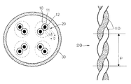
- FIG. 1 is cross sectional view of communication cable according to present invention.
- FIG. 2 is plane view of pairs ( 20 ) in communication cable according to present invention.
- FIG. 3 cross sectional view of communication cable according to example of present invention which comprise separator.
- FIG. 4 is chart showing characteristic value of communication cable according to example of present invention and comparative example.
- FIG. 1 is cross sectional view of communication cable according to present invention
- FIG. 2 is plane view of pairs ( 20 ) in communication cable according to present invention.
- communication cable according to present invention comprises wire ( 10 ) which is constituted by conductor ( 11 ) coated by insulation material ( 12 ) and pairs ( 20 ) which is constituted by twisting said wires ( 10 ) and sheath ( 30 ) wrapping said pairs ( 20 ).
- said electric wires ( 10 ) with diameter D are formed by straight conductor ( 11 ) with diameter d such as copper coated by insulation member ( 12 ) to transmit data transformed into electric signal.
- Said insulation member ( 12 ) are formed by high molecular resin LDPE (Low Density Polyethylene), HDPE (High Density Polyethylene), FEP (Fluorinated Ethylene Propylene), etc which has low dielectric constant and are easy to handle.
- LDPE Low Density Polyethylene
- HDPE High Density Polyethylene
- FEP Fluorinated Ethylene Propylene
- Said pairs ( 20 ) are formed by twisting the electric wires ( 10 ) by constant pitch p, generally as seen in FIG. 1 , two electric wires are twisted, but not limited to this and various modifications can be done.
- the pairs ( 20 ) can be coated on its outer surface of the electric wires ( 10 ) to improve transmitting characteristic by decreasing signal interference by shielding electromagnetic wave.
- the pairs ( 20 ) are comprised in the communication cable of high capacity at least two, generally as seen in FIG. 1 , four pairs ( 14 ) are comprised in the sheath ( 30 ), not limited to this and various modifications can be done.
- the pairs are twisted by different pitch p from one another, preferably by different pitch more than 0.2 mm.
- the total pairs ( 20 ) are twisted by constant pitch, and this twisted pitch of total pairs ( 20 ) is called “collective pitch” P.
- the cable comprises sheath ( 30 ) to form external appearance wrapping the twisted total pairs ( 20 ).
- the sheath ( 30 ) protect the pairs ( 20 ) mechanically and shielding alien cross talk generated by electromagnetic wave from adjacent other cable or electric equipment.
- the sheath ( 30 ) is formed by insulation material such as high molecular resin for example, polyethylene, PVC, or Olefin system and preferably by 0.3 ⁇ 1.5 mm thickness.
- the thickness of the sheath ( 30 ) is under 0.3 mm, the electric wires ( 10 ) can not be protected from the alien crosstalk, and the thickness is over 1.5 mm, the weight of the cable is increased by the thickness and the flexibility of the cable is decreased.
- electromagnetic wave shielding sheath (not illustrated) formed by conductive material can be comprised in the sheath ( 30 ).
- Communication cable of high capacity comprise said elements, and to form communication cable which is proper to high speed transmission, impedance of wires ( 10 ) in cable and impedance of equipment are matched for high speed transmission of data, so return loss of cable can be minimized.
- R, L, G are resistance (R), inductance (L), conductance (G), capacitance (C) of wire ( 10 ) in cable.
- impedance (Z) of said formula (1) at first resistance (R), inductance (L), conductance (G), capacitance (C) should be calculated, about wire ( 10 ) in FIG. 1 comprising conductor ( 11 ) and insulation member ( 12 ), said values can be calculated by following numerical formula.
- ⁇ 0 ⁇ r is dielectric constant of insulation member ( 12 ) ( ⁇ 0 : dielectric constant at vacuum state, ⁇ r : relative dielectric constant), ⁇ 0 ⁇ r is magnetic permeability constant of conductor ( 11 ) ( ⁇ 0 : magnetic permeability constant at vacuum state, ⁇ r : relative magnetic permeability constant), ⁇ is dielectric loss ratio constant.
- impedance of wire ( 10 ) comprising conductor ( 11 ) and insulation member ( 12 ) is determined by diameter of conductor (d) and diameter of wire ( 10 ) (D).
- dielectric constant ( ⁇ 0 ⁇ r ) error generally insulation member ( 12 ) such as HDPE (High Density Polyethylene), FEP etc has dielectric constant from 2.1 to 2.3 and dielectric constant of air is 1, said dielectric constant from said conductors ( 11 ) effect from dielectric of said insulation member and air complexly, so said dielectric constant can not be define exactly.
- dielectric constant ( ⁇ 0 ⁇ r ) error generally insulation member ( 12 ) such as HDPE (High Density Polyethylene), FEP etc has dielectric constant from 2.1 to 2.3 and dielectric constant of air is 1, said dielectric constant from said conductors ( 11 ) effect from dielectric of said insulation member and air complexly, so said dielectric constant can not be define exactly.
- HDPE High Density Polyethylene
- capacitance value is inverse proportional to distance between wires and proportional to size of cross section of wires, increase/decrease of said length increasing rate by twisting wires by pitch (p) and collective pitch (P) make size of cross section of wires increase/decrease in specific area so it effects the capacitance value and varies the impedance value (Z).
- cable according to present invention introduce compensation factor to compensate said errors, and by said formulas following formula can be resulted.
- compensation coefficient A is by dielectric constant of insulation member ( 12 ) ( ⁇ 0 ⁇ r ), magnetic permeability of conductor ( ⁇ 0 ⁇ r ), skin effect, proximity effect, and is from 81 to 83.
- compensation coefficient B is by length increasing rate resulted from capacitance compensated by pitch, collective pitch, and is from 0.005 to 0.007.
- calculation formula for said compensation coefficient A, B is as followings, and a, b is constant.
- said impedance is formed to have range from 90 ⁇ to 110 ⁇ for conforming Cat.6 or Cat.6A which are standard of UTP cable.
- pitches (p) of said pairs ( 20 ) are formed to have range from 8 mm to 25 mm.
- pitches is under 8 mm, total length of wires ( 10 ) are increased by short pitch, so material consumption and transmission loss of data increase, if said pitches are over 25 mm, structure is not stable so it is difficult to keep the structure of pairs ( 20 ).
- relative ratio of diameter of wires ( 10 ) (D) to diameter of conductor (d) D/d is formed to have range from 1.625 to 1.835.
- the range of collective pitch (P) can be set up by pitch (p), ratio of diameter D/d, and numerical formula ( 6 ), and the range of collective pitch (P) is from 40 mm to 150 mm.
- diameter (d) of said conductor is formed to have range from 0.53 mm to 0.65 mm.
- diameter (D) of wire is determined relative to diameter (d) of conductor, 0.53 ⁇ d ⁇ 0.65, in this case, diameter (D) of wire is from 0.9 mm to 1.1 mm.
- said diameter (D) of wire can be different in every pair ( 20 ), in this case if said pitch (p) increase, then diameter (D) of wire is formed to be decreased.
- FIG. 3 cross sectional view of communication cable according to one example of present invention which comprise separator ( 40 ) to separate said plural pairs ( 20 ) from one another.
- said separator ( 40 ) comprises cross separation walls ( 42 , 44 , 46 , 48 ) to separate said pairs ( 20 ).
- said separator ( 40 ) is formed to have helical structure and same pitch with said collective pitch (P) for said plural pairs ( 20 ) being twisted fowling collective pitch (P).
- said separator ( 40 ) can be form in various structure according to the number of said pairs ( 20 ) to separate the same, in case said pairs ( 20 ) is four, preferably as seen in FIG. 3 , the separator ( 40 ) can be formed to have cross structure.
- said cross structure By said cross structure, it can widen distance between each pairs ( 20 ), so can suppress interference between pairs ( 20 ).
- FIG. 4 is chart showing characteristic value of communication cable according to example of present invention and comparative example.
- communication cable according to example of present invention which has conductor of diameter d, wire diameter of D, pitch p, collective pitch P and comparative example are compared with each other.
- two wires ( 10 ) of diameter D which have conductor ( 11 ) of diameter d are twisted with each other by pitch p to form pair ( 20 ), and four pairs are twisted helically by collective pitch P.
- diameter d of conductor is 0.56 mm
- diameter D of wire is 0.99 mm
- pitches p are 12.0 mm, 14.0 mm, 13.0 mm, 15.0 mm respectively
- collective pitch P is 100 mm.
- Did is 1.77, and this value is comprised in the range from 1.625 to 1.835.
- each pair ( 20 ) had 101.5 ⁇ , 102.3 ⁇ , 101.9 ⁇ , 102.7 ⁇ respectively.
- Said impedance is near 100 ⁇ which is suggested by IEEE 802.3 committee and is matching impedance of Cat.6, Cat.6A which enable 10 Gbps rate data transmission, and that means communication cable most suitable for data transmission.
- return loss in network of communication cable according to first example of present invention was 6.5 dB which is excellent.
- comparative example 1 conventional cable is shown in comparative example 1 compared with communication cable according to first example of present invention, and in comparative example 1, diameter of conductor d is 0.56 mm, diameter of wire D is 0.8 mm, pitches p are 12.0 mm, 14.0 mm, 13.0 mm, 15.0 min respectively, and collective pitch P is 100 mm.
- each pair ( 20 ) had 78.9 ⁇ , 79.7 ⁇ , 79.4 ⁇ , 80.1 ⁇ respectively, and these have difference with matching impedance 100 ⁇ of Cat.6, Cat.6A.
- return loss in network of communication cable according to first comparative example was ⁇ 1.0 dB which is inferior to first example of present invention.
- two wires ( 10 ) of diameter D which have conductor ( 11 ) of diameter d are twisted with each other by pitch p to form pair ( 20 ), and four pairs are twisted helically by collective pitch P.
- diameter d of conductor is 0.56 mm
- diameter D of wire is 0.99 mm, 0.97 mm, 0.98 mm, 0.96 mm respectively
- pitches p are 12.0 mm, 14.0 mm, 13.0 mm, 15.0 mm respectively
- collective pitch P is 100 mm.
- each pair ( 20 ) had 101.5 ⁇ , 100.3 ⁇ , 100.9 ⁇ , 99.6 ⁇ respectively.
- Said impedance is near 100 ⁇ which is suggested by IEEE 802.3 committee and is matching impedance of Cat.6, Cat.6A which enable 10 Gbps rate data transmission, and that means communication cable most suitable for data transmission.
- return loss in network of communication cable according to second example of present invention was 7.0 dB which is excellent.
- comparative example 2 conventional cable is shown in comparative example 2, comparative example 3 compared with communication cable according to second example of present invention, and in comparative example 2, diameter of conductor d is 0.56 mm, diameter of wire D is 1.2 mm, pitches p are 12.0 mm, 14.0 mm, 13.0 mm, 15.0 mm respectively, and collective pitch P is 100 mm.
- each pair ( 20 ) had 119.9 ⁇ , 120.7 ⁇ , 120.3 ⁇ , 121.1 ⁇ respectively, and these have difference with matching impedance 100 ⁇ of Cat.6, Cat.6A.
- diameter of conductor d is 0.50 mm
- diameter of wire D is 1.2 mm, 1.5 mm, 1.2 mm, 1.5 mm
- pitches p are 30.0 mm, 30.0 mm, 20.0 mm, 20.0 mm respectively
- collective pitch P is 160 mm.
- each pair ( 20 ) had 137.2 ⁇ , 156.9 ⁇ , 133.7 ⁇ , 153.5 ⁇ respectively, and these have difference with matching impedance 100 ⁇ of Cat.6, Cat.6A.
- return loss in network of communication cable according to second comparative example and third comparative example were ⁇ 1.0 dB, ⁇ 3.0 dB which are inferior to second example of present invention.
- two wires ( 10 ) of diameter D which have conductor ( 11 ) of diameter d are twisted with each other by pitch p to form pair ( 20 ), and four pairs are twisted helically by collective pitch P.
- diameter d of conductor is 0.64 mm
- diameters D of wires are 1.05 mm, 1.05 mm, 1.10 mm, 1.10 mm
- pitches p are 25.0 mm, 20.0 mm, 23.0 mm, 21.0 mm respectively
- collective pitch P is 140 mm.
- Did are 1.64, 1.64, 1.72, 1.72 respectively and this values are comprised in the range from 1.625 to 1.835.
- each pair ( 20 ) had 99.0 ⁇ , 97.3 ⁇ , 103.1 ⁇ , 102.4 ⁇ respectively.
- Said impedance is near 100 ⁇ which is suggested by IEEE 802.3 committee and is matching impedance of Cat.6, Cat.6A which enable 10 Gbps rate data transmission, and that means communication cable most suitable for data transmission.
- return loss in network of communication cable according to third example of present invention was 6.1 dB which is excellent.
- comparative example 4 conventional cable is shown in comparative example 4 compared with communication cable according to third example of present invention, and in comparative example 4, diameter of conductor d is 0.69 mm, diameters of wires D are 0.85 mm, 0.75 mm, 0.80 mm, 0.70 mm respectively, pitch p is 6.0 mm, and collective pitch P is 180 mm.
- each pair ( 20 ) had 57.8 ⁇ , 37.0 ⁇ , 48.7 ⁇ , 17.0 ⁇ respectively, and these have difference with matching impedance 100 ⁇ of Cat.6, Cat.6A.
- two wires ( 10 ) of diameter D which have conductor ( 11 ) of diameter d are twisted with each other by pitch p to form pair ( 20 ), and four pairs are twisted helically by collective pitch P.
- diameter d of conductor is 0.56 mm
- diameter D of wire is 0.91 mm
- pitches p are 12.0 mm, 14.0 mm, 13.0 mm, 15.0 mm respectively
- collective pitch P is 100 mm.
- Did are 1.625 and this value is comprised in the range from 1.625 to 1.835.
- each pair ( 20 ) had 93.0 ⁇ , 93.7 ⁇ , 93.4 ⁇ , 94.1 ⁇ respectively.
- Said impedance is near 100 ⁇ which is suggested by IEEE 802.3 committee and is matching impedance of Cat.6, Cat.6A which enable 10 Gbps rate data transmission, and that means communication cable most suitable for data transmission.
- return loss in network of communication cable according to fourth example of present invention was 5.2 dB which is excellent.
- comparative example 5 conventional cable is shown in comparative example 5 compared with communication cable according to fourth example of present invention, and in comparative example 5, diameter of conductor d is 0.56 mm, diameters of wires D are 0.85 mm, 0.83 mm, 0.84 mm, 0.82 mm respectively, pitches p are 12.0 mm, 14.0 mm, 13.0 mm, 15.0 mm respectively, and collective pitch P is 100 mm.
- each pair ( 20 ) had 85.7 ⁇ , 83.9 ⁇ , 84.8 ⁇ , 82.9 ⁇ respectively, and these approach to 100 ⁇ more than other comparative examples but have difference with matching impedance 100 ⁇ compared with examples of present invention.
- return loss in network of communication cable according to comparative example 5 was 1.0 dB which is superior than other comparative examples but inferior to other examples of present invention.
- two wires ( 10 ) of diameter D which have conductor ( 11 ) of diameter d are twisted with each other by pitch p to form pair ( 20 ), and four pairs are twisted helically by collective pitch P.
- diameter d of conductor is 0.60 mm
- diameter D of wire is 1.10 mm
- pitches p are 12.0 mm, 14.0 mm, 13.0 mm, 15.0 mm respectively
- collective pitch P is 100 mm.
- D/d is 1.833 and this value is comprised in the range from 1.625 to 1.835.
- each pair ( 20 ) had 105.1 ⁇ , 105.9 ⁇ , 105.5 ⁇ , 106.3 ⁇ respectively.
- Said impedance is near 100 ⁇ which is suggested by IEEE 802.3 committee and is matching impedance of Cat.6, Cat.6A which enable 10 Gbps rate data transmission, and that means communication cable most suitable for data transmission.
- return loss in network of communication cable according to fifth example of present invention was 4.3 dB which is excellent.
- comparative example 6 conventional cable is shown in comparative example 6 compared with communication cable according to fifth example of present invention, and in comparative example 6, diameter of conductor d is 0.53 mm, diameters of wires D are 1.15 mm, 1.17 mm, 1.16 mm, 1.17 mm respectively, pitches p are 14.0 mm, 12.0 mm, 15.0 mm, 13.0 mm respectively, and collective pitch P is 90 mm.
- each pair ( 20 ) had 121.8 ⁇ , 122.6 ⁇ , 129.9 ⁇ , 123.0 ⁇ respectively, and these have difference with matching impedance 100 ⁇ of Cat.6, Cat.6A.
- first to fifth examples of communication cable according to present invention have nearer impedance characteristic to 100 ⁇ which enable 10 Gbps data transmission than conventional comparative examples 1 to 6, and shows superior network characteristic to the sames.
Abstract
Description
into formula (1), it should be understandable that impedance of wire (10) comprising conductor (11) and insulation member (12) is determined by diameter of conductor (d) and diameter of wire (10) (D).
increases, and generally collective pitch (P) is bigger than pitch (p), P>p,
. then p must approach to P, so consequently p must be bigger.
Claims (10)
Priority Applications (1)
| Application Number | Priority Date | Filing Date | Title |
|---|---|---|---|
| US12/762,355 US8357855B2 (en) | 2007-04-13 | 2010-04-18 | Communication cable of high capacity |
Applications Claiming Priority (3)
| Application Number | Priority Date | Filing Date | Title |
|---|---|---|---|
| KR1020070036264A KR100825408B1 (en) | 2007-04-13 | 2007-04-13 | Communication cable of high capacity |
| KR10-2007-0036264 | 2007-04-13 | ||
| PCT/KR2008/001587 WO2008126991A1 (en) | 2007-04-13 | 2008-03-21 | Communication cable of high capacity |
Related Parent Applications (1)
| Application Number | Title | Priority Date | Filing Date |
|---|---|---|---|
| PCT/KR2008/001587 A-371-Of-International WO2008126991A1 (en) | 2007-04-13 | 2008-03-21 | Communication cable of high capacity |
Related Child Applications (1)
| Application Number | Title | Priority Date | Filing Date |
|---|---|---|---|
| US12/762,355 Continuation-In-Part US8357855B2 (en) | 2007-04-13 | 2010-04-18 | Communication cable of high capacity |
Publications (2)
| Publication Number | Publication Date |
|---|---|
| US20100108349A1 US20100108349A1 (en) | 2010-05-06 |
| US7718896B1 true US7718896B1 (en) | 2010-05-18 |
Family
ID=39572648
Family Applications (2)
| Application Number | Title | Priority Date | Filing Date |
|---|---|---|---|
| US12/443,774 Active US7718896B1 (en) | 2007-04-13 | 2008-03-21 | Communication cable of high capacity |
| US12/762,355 Active 2029-02-24 US8357855B2 (en) | 2007-04-13 | 2010-04-18 | Communication cable of high capacity |
Family Applications After (1)
| Application Number | Title | Priority Date | Filing Date |
|---|---|---|---|
| US12/762,355 Active 2029-02-24 US8357855B2 (en) | 2007-04-13 | 2010-04-18 | Communication cable of high capacity |
Country Status (3)
| Country | Link |
|---|---|
| US (2) | US7718896B1 (en) |
| KR (1) | KR100825408B1 (en) |
| WO (1) | WO2008126991A1 (en) |
Cited By (3)
| Publication number | Priority date | Publication date | Assignee | Title |
|---|---|---|---|---|
| US20090308634A1 (en) * | 2007-05-17 | 2009-12-17 | Jong-Seb Baeck | Communication cable of high capacity |
| US20100200267A1 (en) * | 2007-04-13 | 2010-08-12 | Ls Cable Ltd. | Communication cable of high capacity |
| US20230060912A1 (en) * | 2021-08-25 | 2023-03-02 | Panduit Corp. | Optimized wire separator for twisted wire-pair applications |
Families Citing this family (15)
| Publication number | Priority date | Publication date | Assignee | Title |
|---|---|---|---|---|
| US8907211B2 (en) | 2010-10-29 | 2014-12-09 | Jamie M. Fox | Power cable with twisted and untwisted wires to reduce ground loop voltages |
| CN103065719A (en) * | 2012-12-10 | 2013-04-24 | 浙江一舟电子科技股份有限公司 | Improvement structure with more than six types of cables |
| US9117566B2 (en) * | 2013-03-14 | 2015-08-25 | Teledyne Instruments, Inc. | Impedance controlled subsea ethernet oil filled hose |
| US20140262411A1 (en) * | 2013-03-15 | 2014-09-18 | Commscope, Inc. Of North Carolina | Extended curl s-shield |
| CN108780680B (en) * | 2016-03-31 | 2020-11-13 | 株式会社自动网络技术研究所 | Electric wire for communication |
| JP6075490B1 (en) | 2016-03-31 | 2017-02-08 | 株式会社オートネットワーク技術研究所 | Shield wire for communication |
| JP2018078007A (en) * | 2016-11-09 | 2018-05-17 | 矢崎総業株式会社 | Aluminum twisted-wire and wire harness |
| DE112017006006T5 (en) * | 2016-11-28 | 2019-08-29 | Autonetworks Technologies, Ltd. | Shielded communication cable |
| CN112614618B (en) * | 2017-02-01 | 2022-12-09 | 株式会社自动网络技术研究所 | Wire for communication |
| US10410768B2 (en) * | 2017-02-28 | 2019-09-10 | Greganna Unlimited Company | Probe assembly having cable assembly with wire pairs |
| WO2020171358A1 (en) * | 2019-02-19 | 2020-08-27 | 엘에스전선 주식회사 | Ethernet cable |
| KR102181049B1 (en) * | 2019-02-19 | 2020-11-19 | 엘에스전선 주식회사 | Ethernet cable |
| JP6955530B2 (en) * | 2019-05-20 | 2021-10-27 | 矢崎総業株式会社 | Bending resistant communication cable and wire harness |
| US20230335314A1 (en) * | 2020-09-01 | 2023-10-19 | Ls Cable & System Ltd. | Poe cable |
| US11682501B2 (en) * | 2020-09-22 | 2023-06-20 | Belden Inc. | Hybrid high frequency separator with parametric control ratios of conductive components |
Citations (12)
| Publication number | Priority date | Publication date | Assignee | Title |
|---|---|---|---|---|
| US5253317A (en) * | 1991-11-21 | 1993-10-12 | Cooper Industries, Inc. | Non-halogenated plenum cable |
| US5298680A (en) * | 1992-08-07 | 1994-03-29 | Kenny Robert D | Dual twisted pairs over single jacket |
| US5378856A (en) * | 1992-12-11 | 1995-01-03 | Belden Wire & Cable Company | Transmission cable having a nonhalogenated jacket formulation |
| US5493071A (en) * | 1994-11-10 | 1996-02-20 | Berk-Tek, Inc. | Communication cable for use in a plenum |
| US5619016A (en) * | 1995-01-31 | 1997-04-08 | Alcatel Na Cable Systems, Inc. | Communication cable for use in a plenum |
| US5883334A (en) * | 1995-06-13 | 1999-03-16 | Alcatel Na Cable Systems, Inc. | High speed telecommunication cable |
| US5936205A (en) * | 1994-11-10 | 1999-08-10 | Alcatel | Communication cable for use in a plenum |
| JP2000195346A (en) | 1998-12-25 | 2000-07-14 | Fujikura Ltd | Communication cable |
| US6333465B1 (en) * | 1997-11-27 | 2001-12-25 | Alcatel | Data transmission cable |
| KR20020044110A (en) | 1999-05-28 | 2002-06-14 | 토드 엠. 뒤센 | Optimized lan cable and method for manufacturing the same |
| JP2003036739A (en) | 2001-07-19 | 2003-02-07 | Fujikura Ltd | Communication cable |
| KR20070023636A (en) | 2003-10-31 | 2007-02-28 | 에이디씨 인코포레이티드 | Cable with Eccentric Filler |
Family Cites Families (6)
| Publication number | Priority date | Publication date | Assignee | Title |
|---|---|---|---|---|
| US3546357A (en) * | 1969-01-03 | 1970-12-08 | Bell Telephone Labor Inc | Cable with fully controllable pair twist length |
| US4697051A (en) * | 1985-07-31 | 1987-09-29 | At&T Technologies Inc., At&T Bell Laboratories | Data transmission system |
| US5162609A (en) * | 1991-07-31 | 1992-11-10 | At&T Bell Laboratories | Fire-resistant cable for transmitting high frequency signals |
| US6194663B1 (en) * | 1997-02-28 | 2001-02-27 | Lucent Technologies Inc. | Local area network cabling arrangement |
| CN100505520C (en) * | 2004-07-23 | 2009-06-24 | 罗姆股份有限公司 | Amplifier circuit, semiconductor device and electronic apparatus |
| KR100825408B1 (en) * | 2007-04-13 | 2008-04-29 | 엘에스전선 주식회사 | Communication cable of high capacity |
-
2007
- 2007-04-13 KR KR1020070036264A patent/KR100825408B1/en active IP Right Review Request
-
2008
- 2008-03-21 WO PCT/KR2008/001587 patent/WO2008126991A1/en active Application Filing
- 2008-03-21 US US12/443,774 patent/US7718896B1/en active Active
-
2010
- 2010-04-18 US US12/762,355 patent/US8357855B2/en active Active
Patent Citations (12)
| Publication number | Priority date | Publication date | Assignee | Title |
|---|---|---|---|---|
| US5253317A (en) * | 1991-11-21 | 1993-10-12 | Cooper Industries, Inc. | Non-halogenated plenum cable |
| US5298680A (en) * | 1992-08-07 | 1994-03-29 | Kenny Robert D | Dual twisted pairs over single jacket |
| US5378856A (en) * | 1992-12-11 | 1995-01-03 | Belden Wire & Cable Company | Transmission cable having a nonhalogenated jacket formulation |
| US5493071A (en) * | 1994-11-10 | 1996-02-20 | Berk-Tek, Inc. | Communication cable for use in a plenum |
| US5936205A (en) * | 1994-11-10 | 1999-08-10 | Alcatel | Communication cable for use in a plenum |
| US5619016A (en) * | 1995-01-31 | 1997-04-08 | Alcatel Na Cable Systems, Inc. | Communication cable for use in a plenum |
| US5883334A (en) * | 1995-06-13 | 1999-03-16 | Alcatel Na Cable Systems, Inc. | High speed telecommunication cable |
| US6333465B1 (en) * | 1997-11-27 | 2001-12-25 | Alcatel | Data transmission cable |
| JP2000195346A (en) | 1998-12-25 | 2000-07-14 | Fujikura Ltd | Communication cable |
| KR20020044110A (en) | 1999-05-28 | 2002-06-14 | 토드 엠. 뒤센 | Optimized lan cable and method for manufacturing the same |
| JP2003036739A (en) | 2001-07-19 | 2003-02-07 | Fujikura Ltd | Communication cable |
| KR20070023636A (en) | 2003-10-31 | 2007-02-28 | 에이디씨 인코포레이티드 | Cable with Eccentric Filler |
Cited By (5)
| Publication number | Priority date | Publication date | Assignee | Title |
|---|---|---|---|---|
| US20100200267A1 (en) * | 2007-04-13 | 2010-08-12 | Ls Cable Ltd. | Communication cable of high capacity |
| US8357855B2 (en) * | 2007-04-13 | 2013-01-22 | Ls Cable & System Ltd. | Communication cable of high capacity |
| US20090308634A1 (en) * | 2007-05-17 | 2009-12-17 | Jong-Seb Baeck | Communication cable of high capacity |
| US7910835B2 (en) * | 2007-05-17 | 2011-03-22 | Ls Cable Ltd. | Communication cable of high capacity |
| US20230060912A1 (en) * | 2021-08-25 | 2023-03-02 | Panduit Corp. | Optimized wire separator for twisted wire-pair applications |
Also Published As
| Publication number | Publication date |
|---|---|
| US8357855B2 (en) | 2013-01-22 |
| KR100825408B9 (en) | 2022-02-14 |
| KR100825408B1 (en) | 2008-04-29 |
| US20100200267A1 (en) | 2010-08-12 |
| WO2008126991A1 (en) | 2008-10-23 |
| US20100108349A1 (en) | 2010-05-06 |
Similar Documents
| Publication | Publication Date | Title |
|---|---|---|
| US7718896B1 (en) | Communication cable of high capacity | |
| CN104616822B (en) | Differential signaling cable and transmission cable assembly using the same, and production method for differential signaling cable | |
| US6150612A (en) | High performance data cable | |
| US8785782B2 (en) | UTP cable of improved alien crosstalk characteristic | |
| KR100690117B1 (en) | Communication cables with outside spacer and method for producing the same | |
| US20030150633A1 (en) | Data transmission cable | |
| CN102054544A (en) | Differential signal transmission cable | |
| US20190080823A1 (en) | Cable for transmitting electrical signals | |
| US10950368B2 (en) | I-shaped filler | |
| US20070026742A1 (en) | UTP cable for transmitting high frequency signal | |
| CN107170525B (en) | Differential transmission cable and multi-pair differential transmission cable | |
| US7910835B2 (en) | Communication cable of high capacity | |
| KR101387241B1 (en) | Data cable for high speed communication except for cross-filler | |
| EP4280231A1 (en) | Data transmission cable | |
| CN212907226U (en) | Computer cable for automatic identification system | |
| KR20110082341A (en) | Data communication cable | |
| WO2010018890A1 (en) | Unshielded twisted pair cable | |
| KR100969275B1 (en) | Utp cable | |
| US10049791B2 (en) | Differential transmission cable and multipair differential transmission cable | |
| EP3422368A1 (en) | Channeled insulation for conductor of telecommunication cable | |
| JP2000195346A (en) | Communication cable | |
| KR20180108524A (en) | Electromagnetic Wave Shield Tape and Communication Cable Having The Same | |
| Bell | Different types of transmission lines used in communications: applications and uses. |
Legal Events
| Date | Code | Title | Description |
|---|---|---|---|
| AS | Assignment |
Owner name: LS CABLE LTD.,KOREA, REPUBLIC OF Free format text: ASSIGNMENT OF ASSIGNORS INTEREST;ASSIGNORS:BAECK, JONG-SEB;OK, SOO-GON;REEL/FRAME:022888/0519 Effective date: 20090610 |
|
| STCF | Information on status: patent grant |
Free format text: PATENTED CASE |
|
| FEPP | Fee payment procedure |
Free format text: PAYOR NUMBER ASSIGNED (ORIGINAL EVENT CODE: ASPN); ENTITY STATUS OF PATENT OWNER: LARGE ENTITY |
|
| FPAY | Fee payment |
Year of fee payment: 4 |
|
| MAFP | Maintenance fee payment |
Free format text: PAYMENT OF MAINTENANCE FEE, 8TH YEAR, LARGE ENTITY (ORIGINAL EVENT CODE: M1552) Year of fee payment: 8 |
|
| AS | Assignment |
Owner name: LS CORPORATION, KOREA, REPUBLIC OF Free format text: CHANGE OF NAME;ASSIGNOR:LS CABLE LTD;REEL/FRAME:056556/0718 Effective date: 20080711 Owner name: LS CABLE & SYSTEM LTD., KOREA, REPUBLIC OF Free format text: ASSIGNMENT OF ASSIGNORS INTEREST;ASSIGNOR:LS CORPORATION;REEL/FRAME:056510/0810 Effective date: 20210609 |
|
| MAFP | Maintenance fee payment |
Free format text: PAYMENT OF MAINTENANCE FEE, 12TH YEAR, LARGE ENTITY (ORIGINAL EVENT CODE: M1553); ENTITY STATUS OF PATENT OWNER: LARGE ENTITY Year of fee payment: 12 |