US7719981B2 - Adaptive transmission in multi-access asynchronous channels - Google Patents
Adaptive transmission in multi-access asynchronous channels Download PDFInfo
- Publication number
- US7719981B2 US7719981B2 US10/884,641 US88464104A US7719981B2 US 7719981 B2 US7719981 B2 US 7719981B2 US 88464104 A US88464104 A US 88464104A US 7719981 B2 US7719981 B2 US 7719981B2
- Authority
- US
- United States
- Prior art keywords
- network
- transmission
- channel
- network entity
- channels
- Prior art date
- Legal status (The legal status is an assumption and is not a legal conclusion. Google has not performed a legal analysis and makes no representation as to the accuracy of the status listed.)
- Expired - Lifetime, expires
Links
- 230000005540 biological transmission Effects 0.000 title claims abstract description 293
- 230000003044 adaptive effect Effects 0.000 title claims abstract description 33
- 238000000034 method Methods 0.000 claims description 26
- 238000004891 communication Methods 0.000 claims description 16
- 238000001514 detection method Methods 0.000 claims description 9
- 101100172132 Mus musculus Eif3a gene Proteins 0.000 abstract description 12
- 238000004364 calculation method Methods 0.000 abstract description 2
- 230000007704 transition Effects 0.000 description 16
- 238000004422 calculation algorithm Methods 0.000 description 15
- 108700026140 MAC combination Proteins 0.000 description 14
- 238000004088 simulation Methods 0.000 description 14
- 239000003795 chemical substances by application Substances 0.000 description 13
- 238000010586 diagram Methods 0.000 description 12
- 230000008569 process Effects 0.000 description 12
- 230000001965 increasing effect Effects 0.000 description 7
- 230000000694 effects Effects 0.000 description 6
- 230000007246 mechanism Effects 0.000 description 6
- 239000000203 mixture Substances 0.000 description 6
- 230000008901 benefit Effects 0.000 description 4
- 230000015654 memory Effects 0.000 description 4
- 230000009471 action Effects 0.000 description 3
- 230000015556 catabolic process Effects 0.000 description 3
- 238000006731 degradation reaction Methods 0.000 description 3
- 238000012545 processing Methods 0.000 description 3
- 230000001934 delay Effects 0.000 description 2
- 238000005457 optimization Methods 0.000 description 2
- 230000008447 perception Effects 0.000 description 2
- 230000000737 periodic effect Effects 0.000 description 2
- 230000011664 signaling Effects 0.000 description 2
- 125000002015 acyclic group Chemical group 0.000 description 1
- 230000003466 anti-cipated effect Effects 0.000 description 1
- 238000013459 approach Methods 0.000 description 1
- 230000008859 change Effects 0.000 description 1
- 230000001186 cumulative effect Effects 0.000 description 1
- 230000003111 delayed effect Effects 0.000 description 1
- 230000001419 dependent effect Effects 0.000 description 1
- 239000000284 extract Substances 0.000 description 1
- 230000002349 favourable effect Effects 0.000 description 1
- 239000000835 fiber Substances 0.000 description 1
- 230000006870 function Effects 0.000 description 1
- 238000009396 hybridization Methods 0.000 description 1
- 230000006872 improvement Effects 0.000 description 1
- 230000001939 inductive effect Effects 0.000 description 1
- 230000004048 modification Effects 0.000 description 1
- 238000012986 modification Methods 0.000 description 1
- 230000002085 persistent effect Effects 0.000 description 1
- 238000009877 rendering Methods 0.000 description 1
- 230000003252 repetitive effect Effects 0.000 description 1
- 230000000717 retained effect Effects 0.000 description 1
- 238000001228 spectrum Methods 0.000 description 1
- 238000010561 standard procedure Methods 0.000 description 1
- 230000002459 sustained effect Effects 0.000 description 1
- 208000024891 symptom Diseases 0.000 description 1
- 230000001360 synchronised effect Effects 0.000 description 1
- 238000012360 testing method Methods 0.000 description 1
- 239000002699 waste material Substances 0.000 description 1
Images


Classifications
-
- H—ELECTRICITY
- H04—ELECTRIC COMMUNICATION TECHNIQUE
- H04L—TRANSMISSION OF DIGITAL INFORMATION, e.g. TELEGRAPHIC COMMUNICATION
- H04L12/00—Data switching networks
- H04L12/28—Data switching networks characterised by path configuration, e.g. LAN [Local Area Networks] or WAN [Wide Area Networks]
- H04L12/40—Bus networks
- H04L12/407—Bus networks with decentralised control
- H04L12/413—Bus networks with decentralised control with random access, e.g. carrier-sense multiple-access with collision detection (CSMA-CD)
-
- H—ELECTRICITY
- H04—ELECTRIC COMMUNICATION TECHNIQUE
- H04L—TRANSMISSION OF DIGITAL INFORMATION, e.g. TELEGRAPHIC COMMUNICATION
- H04L12/00—Data switching networks
- H04L12/28—Data switching networks characterised by path configuration, e.g. LAN [Local Area Networks] or WAN [Wide Area Networks]
- H04L12/40—Bus networks
- H04L12/403—Bus networks with centralised control, e.g. polling
- H04L12/4035—Bus networks with centralised control, e.g. polling in which slots of a TDMA packet structure are assigned based on a contention resolution carried out at a master unit
Definitions
- the present invention relates generally to communication between multiple devices over a single, shared transmission medium, and more specifically to employing an adaptive medium access control protocol together with a corresponding logical link control protocol supporting adaptive channel allocation to improve device communication over a shared transmission medium.
- Token ring and token bus schemes control access to the transmission medium in an orderly fashion designed to maximize bandwidth utilization and to maintain fairness (priorities) and determinism.
- Token ring and token bus schemes may be viewed as forms of multiplexing (MUXing), which may be loosely defined as combining two or more information channels onto a common transmission medium.
- MUXing multiplexing
- Each timeslot is then uniquely assigned to a single transmitting entity, which owns the medium for the full duration of the timeslot and may transmit on the medium only during that assigned portion of time, and is the only transmitting entity permitted to transmit during that assigned portion of time.
- Time division multiplexing thus achieves shared access to a single transmission medium by defined division of transmission time among the transmitting entities.
- STDM statistical time division multiplexing
- Ethernet-type medium access control schemes generally allow a network element to transmit at will on the transmission medium. While non-deterministic in nature, this system possesses several attractive characteristics, including simplicity, support for dynamic changes in network element population, autonomous network element operation, low transmission latency at low utilization levels, and acceptable throughput under average loading conditions. Drawbacks of Ethernet include degradation of throughput under heavy traffic loading, non-determinism, and absence of priority assurance. Ethernet throughput rates are typically in the range of 20% to 50% depending on the specific implementation, and drop drastically from those levels when the transmission medium is heavily loaded.
- Current Ethernet transmission medium access control utilizes the truncated binary exponential back-off algorithm, a simple algorithm by which a transmission controller chip may adapt access to the medium according to the medium loading condition. The basic outcome of the algorithm is minimal latency and acceptable throughput and utilization under light loading conditions, with increased latency and acceptable throughput and bandwidth utilization as traffic increases towards heavy traffic conditions.
- a hybrid transmission cycle (HTC) unit of bandwidth on a shared transmission medium is defined to include an adaptive, time division multiplexing transmission cycle (ATTC), which is allocated in portions sequentially among all participating network entities, and a residual transmission cycle (RTC), which is allocated in portions, as available, to the first network entity requesting access to the shared medium during each particular portion.
- TTC time division multiplexing transmission cycle
- RTC residual transmission cycle
- the ratio of logical link virtual channels, or D-Channels, to data payload virtual channels, or B-Channels, within the ATTC is adaptive depending on loading conditions. Based on transmission profiles transmitted on the D-Channels during the ATTC, each network entity determines how many B-Channels it will utilize within the current HTC.
- This calculation may be based on any decision network, such as a decision network modelling the transmission medium as a marketplace and employing microeconomic principles to determine utilization.
- the ratio of the duration of the ATTC segment to the duration of the RTC segment is also adaptive depending on loading conditions, to prevent unacceptable latency for legacy network entities employing the shared transmission medium.
- utilization of the shared medium preferably reverts to IEEE 802.3 compliant CSMA/CD transmission, including transmissions by HTC-compliant network entities.
- FIG. 1 depicts a block diagram of a network in which a preferred embodiment of the present invention may be implemented
- FIG. 2 is a system architecture diagram for a network element in accordance with a preferred embodiment of the present invention
- FIGS. 3A-3C depict a hybrid transmission cycle employed for transmission on a shared medium in accordance with a preferred embodiment of the present invention
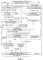
- FIG. 4 is a state diagram for the medium access control (MAC) transmission protocol within a network entity in accordance with a preferred embodiment of the present invention
- FIG. 5 depicts a protocol hierarchy diagram for adaptive channel allocation in accordance with a preferred embodiment of the present invention
- FIG. 6 is a high level flow chart summarizing a process of adaptive channel allocation in accordance with a preferred embodiment of the present invention.
- FIG. 7 depicts a decision network for adaptive channel allocation in accordance with an exemplary embodiment of the present invention.
- FIGS. 8A-8K are plots from simulations of a shared transmission medium utilizing standard 802.3 compliant and/or HTC-compliant network communications under various conditions and combinations of network elements.
- Network 102 includes a plurality of network entities 104 a - 104 n coupled to a shared transmission medium 106 .
- Network entities 104 a - 104 n may be data processing systems including network interface cards or adapters, or may be communications devices such as telephone handsets or the like.
- Shared transmission medium 106 may be coaxial cable, RJ-11 wiring, line-of-sight radio frequency (RF) spectrum, or some similar wired or wireless transmission medium. While not limited, the number of network entities 104 a - 104 n which share a single network transmission medium 106 , should be reasonable. An excessive number (e.g., 500 or more) of network entities 104 a - 104 n within a single network 102 will, even when they have nothing to transmit, waste significant bandwidth in the present invention.
- RF radio frequency
- network entity 104 includes an Ethernet controller chip 204 which interfaces directly with the Ethernet transceiver 206 and the shared transmission medium (e.g., wire) 106 .
- Ethernet controller chip 204 generally conforms to the Ethernet standard, with the exception of differences specifically noted below, and is controlled by an Ethernet software driver 208 , which interfaces with controller chip 204 by Direct Memory Access (DMA) and interrupt processing, a standard technique for implementing Ethernet controllers and corresponding driver software.
- DMA Direct Memory Access
- Ethernet controller chip 204 and Ethernet software driver 208 utilize the IEEE 802.3 Carrier Sense Multiple Access with Collision Detect (CSMA/CD) mechanism for controlling access to shared transmission medium 106 .
- CSMA/CD Carrier Sense Multiple Access with Collision Detect
- Any transmission medium employed by several transmitting entities requires a method of controlling access to the shared medium to ensure that only one transmitting entity transmits on the medium at a given time in order to prevent interference between competing transmissions.
- “Contention” refers to the circumstance in which two or more transmitting entities seek access to the shared medium at the same time. In general, contention does not necessarily implicate “collision,” or interference of competing signals on the shared physical medium, but collision does indicate contention.
- CSMA/CD is a contention resolution protocol which utilizes collision detection to infer contention, and is employed by Ethernet and the present invention to control access to the shared transmission medium.
- Ethernet controller 204 obeys the CSMA/CD protocol transmission state machine which, before transmitting, monitors the carrier sense and collision signals on shared transmission medium 106 for network activity. If another network entity (also referred to as “node”) is currently transmitting on the shared medium 106 , the controller 204 defers transmission until the network is quiet, and then transmits.
- the Ethernet controller 204 detects that the shared medium 106 is idle, it begins transmission. If a collision is detected because another controller had also detected the medium to be idle and began transmission at the same time, both controllers will abort the transmission.
- the controller 204 switches from transmitting data to transmitting a 4-byte JAM pattern (4-bytes, all logical 1's) before ceasing transmission.
- the controller 204 then randomly selects a time duration to back-off before attempting to transmit again. That is, the controller 204 waits a random number of slot times (51.2 ⁇ s) determined by the “truncated binary exponential back-off algorithm” before reattempting another transmission.
- the controller 204 will randomly select a back-off time duration rt, where t is the slot time and r is a random integer selected from the interval 0 ⁇ r ⁇ 2 1 . If, after the selected back-off duration t has expired, the controller 204 still encounters a collision, then the controller 204 selects a new random back-off duration slot time multiple from the interval 0 ⁇ r ⁇ 2 2 .
- the process continues expanding the range of selection by increasing the exponent of the upper limit for the selected slot time multiple for each collision detected. Under the current standard specified in IEEE 802.3, the exponent may reach a maximum of 10.
- the upper limit of the exponent k employed in selecting a back-off duration, and whether or not to employ a backoff algorithm is determined by controller 204 .
- the value of exponent k is configurable, and is set in accordance with standard 802.3 requirements only during the RTC (Residual Transmission Cycle).
- the exponent k value is set to a maximum of 6 when the ethernet controller is attempting transmission of a Join D-Channel frame, a value selected to accommodate a worst case scenario when 2 6 (64) network entities are attempting simultaneous Join D-Channel frame transmissions.
- the ethernet controller does not back off and immediately retransmits during the ATTC phase.
- the paramount benefit of conventional Ethernet controllers which employ a maximum value of 10 for the exponent k within the back-off algorithm is that collisions occurring under low traffic loads will be reattempted shortly after the collision occurs since the back-off duration is initially selected from a shorter interval t, e.g., 0 ⁇ t ⁇ 2 3 (51.2 ⁇ s) for the first three collisions.
- the back-off duration is selected from a wider range, thus delaying transmission attempts and increasing latency. Latency may be defined as the amount of time which a transmitter entity must wait before gaining access to a shared transmission medium.
- latency increase with traffic load is less predictable.
- the conventional Ethernet controller effectively achieves a wider spread of transmission attempts as the shared medium becomes more heavily loaded. The result is automatic and deliberate increase in latency as the number of consecutive collisions increases.
- the present invention effectively neuters the Ethernet truncated binary back-off algorithm during the ATTC and renders the controller 204 aggressive in the event of collision detection.
- the controller 204 does not back off; after sixteen transmission attempts, however, the controller 204 will abort transmission of the packet and report an “excessive collisions” error message to driver 208 .
- Software driver 208 receives data frames from medium access control (MAC) protocol layer 210 .
- MAC medium access control
- the layer two entity submits all of the frames which it has to transmit to the driver at once, and the driver may, in turn, buffer several or all of these frames in the DMA area before issuing a transmit command to the Ethernet controller chip
- the MAC layer 210 controls when and how many frames are submitted to driver 208 , although driver 208 may still buffer frames.
- MAC layer 210 provides intelligent control over when and what is transmitted on shared medium 106 , a feature made possible by advances in processor speeds and memory availability.
- MAC layer 210 employs elastic time division multiplexing (TDM) over an asynchronous multi access channel.
- TDM elastic time division multiplexing
- an adaptive channel allocation protocol (ACAP) layer 212 is implemented as a logical link control (LLC) protocol.
- ACAP layer 212 serves as a decision theoretic agent utilizing a decision network (influence diagram) 214 to process current network loading conditions and, after determining allocation requirements and optimizing the decision network, adapting the bearer channel transmission profile by changing its transmission concentration ratio and its transmission cycle component ratios.
- ACAP layer 212 issues instructions in the form of primitives to MAC layer 210 to execute the results of the decision network optimization.
- ACAP agent 212 modifies these two values (TCR and ATTC:RTC ratio) to maximize transmission success within current network conditions.
- ACAP API 218 is a set of routines which access the requisite methods within ACAP agent 212 , preferably maintained to a minimum of “transmit” and “receive” routines, and an optional “submit” routine providing a suggestion mechanism for user applications 216 to communicate respective future data transmission requirements.
- FIG. 3A is a hybrid transmission cycle (HTC) 302 , the format by which network entities perceive the shared transmission medium.
- the medium is available for transmission only to the extent that virtual channels (VC) within the HTC 302 are idle.
- HTC 302 is a unit of bandwidth which is variable in size and decomposes into several virtual channels of varying sizes.
- the bandwidth sum of the virtual channels contained in an HTC 302 equals the total bandwidth of the HTC 302 . Transmission by a network entity during an HTC 302 may only occur at the boundary of a virtual channel.
- Virtual channels 304 are of two types: data link channels (“D-Channels”) 306 and data bearer channels (“B-Channels”) 308 .
- D-Channels 306 serve as control and signaling channels while B-Channels 308 are payload data channels.
- Negotiation for B-Channel acquisition and relinquishing by a particular network entity is conducted utilizing a protocol over the D-Channel for that network entity.
- HTC 302 is a repeating format of virtual transmission channels which may be assigned differently from one cycle to the next based on control information exchanged over the D-Channels.
- Each HTC 302 includes an adaptive TDM transmission cycle (ATTC) 310 followed by a residual transmission cycle (RTC) 312 .
- Each ATTC 310 includes many virtual channels, and begins with one D-Channel followed by zero or more B-Channels, followed by a second D-Channel and zero of more B-Channels, and so on. D-Channels are dedicated to the exchange of control information, and each network element on the shared transmission medium will have a reserved D-Channel in the ATTC 310 of each HTC 302 .
- a network entity wishing to retain ownership of its B-Channel position within the ATTC 310 must mandatorily transmit a transmission profile on its D-Channel.
- a network entity which fails to transmit a transmission profile on its assigned D-Channel is deemed to no longer exist, and its D-Channel slot is assumed by the next higher network entity.
- a shift left operation is performed on subsequent D-Channel slots such that the resulting ATTC 310 includes sequentially incrementing D-Channel numbers.
- FIGS. 3B and 3C depict the ATTC 310 and the RTC 312 , respectively, in greater detail.
- the designation “D 1 ” is employed to indicate D-Channel 1 , “D 2 ” to identify D-Channel 2 , and so on.
- the designation “D nX ” indicates the nth D-Channel of the transmission cycle, and also indicates that the network entity owning that virtual channel does not wish to transmit any B-Channel data at this time.
- the designation “D nF ” identifies the nth D-Channel in the cycle as the final D-Channel for the cycle. A designation of “D nXF ” is therefore possible.
- B 1 identifies the first B-Channel for a given network entity
- B nF indicates that the identified B-Channel is the final B-Channel for the network entity owning the transmission sub-cycle (identified by 310 a , 310 b , and 310 n in FIG. 3 ).
- B-Channel identifiers do not include the sub-cycle identifier (e.g., as belonging to network entity “ 3 ”) since that may be inferred from the context of the transmission time.
- the designation “D 1R ” indicates the beginning of the RTC 312 , and that network entity “ 1 ” is transmitting the synchronization signal described in further detail below.
- the designation “D 3RF ” identifies the final synchronization signal in the RTC 312 portion of HTC 302 .
- the maximum transmission concentration ratio is the ratio of B-Channel to D-Channel quantities. For instance, an MTCR of 50:1 means that every D-Channel may be immediately followed by a maximum of up to fifty B-Channels.
- the MTCR ensures a certain level of granularity in the transmission cycle which has acceptable performance characteristics. It would be inefficient, for example, to have 10 D-Channels (corresponding to 10 network entities) and only 10 B-Channels, at most, per D-channel, a granularity which could result in half the bandwidth being allocated to data link signaling and half allocation to payload traffic, a poor allocation scheme.
- the MTCR is a fixed ratio serving as a limit for a transmission concentration ratio (TCR), which is the actual concentration ratio employed by a network entity.
- TCR transmission concentration ratio
- the TCR is adaptive to network loading conditions and other factors. Run time adaption of the TCR is fundamental to adaptive transmission.
- the MTCR ensures that a network entity assigned a late sub-cycle in the HTC 302 is not excessively delayed in gaining access to the shared medium. Additionally, the MAC protocol is capable of coexisting with conventional 802.3 Ethernet implementations (normal 802.3 Ethernet transmission is conducted during the RTC 312 ). It is necessary, therefore, that the RTC 312 appear quickly enough within the HTC 302 to avoid inducing unacceptable latency in conventional 802.3 Ethernet implementations sharing the same transmission medium.
- the MTCR places a maximum limit on duration of the ATTC 310 .
- the MTCR also ensures correct acquisition of a sub-cycle by new network entities, and specifies the maximum number of network entities permitted on the network, which may be obtained from:
- the MTCR is a preconfigured quantity, much like the maximum transmission unit (MTU) and minimum frame length employed by conventional 802.3 Ethernet implementations. However, the MTCR serves as a boundary value, with the actual TCR fluctuating at run time.
- the open 802.3 transmission time within the RTC 312 should be set to a ratio of the pre-configured MTCR; for an open transmission time/MTCR ratio of 1 and for an MTCR of 50, the open 802.3 transmission time will be 50 MTU transmission time.
- the RTC 312 should also be required to have an overall minimum length of one MTCR. No length restriction need be imposed on the length of a B-Channel save the standard 802.3 minimum frame length of 64 bytes and the maximum of 1,518 bytes.
- a D-Channel within the ATTC 310 is identified by an integer number, with the first D-Channel having the identifier 1 and the second D-Channel having the identifier 2, etc.
- This identifier is also assigned to the network entity which acquires that D-Channel. For instance, when the shared medium is idle, as in the case of an inactive network, a network element connecting to the medium will enter a listen mode and attempt to detect D-Channel transmissions. If no D-Channel is detected, the network entity assumes itself to be the first to appear on the identifier and assigns itself an identifier of 1, claiming the first sub-cycle within the ATTC 310 . Thereafter the network entity initiates an HTC 302 by transmitting a D-Channel transmission profile.
- the sole network entity transmitting according to the adaptive MAC protocol of the present invention will result in an HTC 302 having only one transmission sub-cycle within the ATTC 310 , with one D-Channel and 50 B-Channel under a default MTCR of 50 and a RTC 312 of 50 MTU, assuming a 1:1 ratio of ATTC 310 to RTC 312 .
- HTC 302 is a repetitive transmission lifetime consisting of one or more transmission sub-cycles within the ATTC 310 followed by the RTC 312 .
- a sub-cycle in an ATTC 310 belongs to a particular network entity, and at the beginning of each sub-cycle a network element will declare its B-Channel allocation requirements and assignments over the D-Channel, then proceed to utilize the B-Channels accordingly.
- a sub-cycle thus consists of only one D-Channel and zero or more B-Channels.
- the B-Channels should be significantly greater in number and bandwidth that the D-Channels.
- the concentration ratio should not be excessive such that network entities wishing to change an allocation scheme are prevented from doing so within a reasonable amount of time.
- D-Channels and B-Channels are interleaved over the full ATTC 310 , each interleaved set consisting of one D-Channel and zero or more B-Channels all belonging to a particular network entity.
- Such interleaving improves latency for the network entities, allowing a network entity to transmit immediately after performing the transmission profile broadcast over its D-Channel and permitting other network entities to perform computation of current network conditions and belief updating in corresponding decision networks.
- Transmission priorities are configurable by software. When priorities are not otherwise assigned to network entities, each network entity will have a priority equivalent to its D-Channel sub-cycle number within the ATTC 310 , with 1 being the highest priority.
- Network entities are assigned a unique integer identification number, starting from 1, when joining the transmission protocol, an assignment made by the network entity itself after observing what other network entities are transmitting on the medium over the D-Channel.
- the network entity identifier specifies the sub-cycle within the ATTC 310 which is owned by the respective network entity.
- the run time network-entity identifier also serves as the network entity priority in the event that no configuration of priority is performed for the network entity. Under this default system, a network entity identifier value of 1 indicates the highest priority network entity and also means that the corresponding network entity was the first, or earliest, to appear on the medium.
- Network entity priority is computed as follows:
- R i 1 id where R i is the priority and “id” is the network entity identifier.
- a network entity When a network entity wishes to join the medium for the first time, after power up, for example, that network entity listens for D-Channel transmissions on the shared medium. Upon detecting a D-Channel transmission, the highest currently-assigned network entity identifier may be read from the transmission profile. The network entity then assigns itself the next higher network entity identifier, as described below. the network entity with an identifier value of 1 transmits on D-Channel D 1 , the network entity with an identifier value of 2 transmits on D-Channel D 2 , etc. Additionally, the B-Channels immediately follow the D-Channel owned by a network entity. As a result, the first transmission sub-cycle within the ATTC 310 is owned by network entity 1 , the second sub-cycle is owned by network entity 2 , and so on.
- the RTC 312 is included, providing a duration of time occurring immediately following the ATTC 310 during which normal 802.3 Ethernet CSMA/CD compliant transmission occurs.
- the shared medium reverts to be a free-for-all just as in conventional 802.3 Ethernet implementations, and network entities employing the adaptive MAC protocol of the present invention also revert to this mode for the duration of the RTC 312 .
- Network entities employing the adaptive MAC protocol of the present invention utilize a non-back off transmission mode during the ATTC.
- the adaptive MAC layer of network entities in accordance with the present invention implements the 802.3 Ethernet transmission state machine during the RTC, as described in further detail below, giving the illusion of a compliant 802.3 chipset.
- Every network element on the shared medium will have a run-time designated D-Channel on which that network element is obligated to transmit.
- This D-Channel is employed to carry transmission profile information constructed by the network entity.
- the network entity assigned to that sub-cycle constructs and transmits a transmission profile over the D-Channel, which is therefore a datalink or control information carrier over which network entities exchange transmission profile information.
- the transmission profile content is employed by each network entity to inform the network population of its B-Channel allocation, mainly represented by two quantities: its current TCR and its ATTC:RTC ratio. Every transmission on a virtual channel is tagged with the identity of the virtual channel in order to ensure continuous global synchronization of participating network entities. Therefore, Ethernet controller chipsets within the compliant network entities should be configured either to operate in the promiscuous mode or to accept multicast MAC addresses.
- Table I describes the format of a D-Channel frame in accordance with the present invention.
- the D-Channel frame is distinguished from conventional 802.3 Ethernet frames by the length (or “Type”) field, common to both frame formats, which may contain a type identifier value, currently-unassigned (see RFC-1700), of decimal 2,047, hexadecimal 7FF.
- the FrameId number is placed after the type field in the D-Channel frame format, containing an encoded value indicating the D-Channel identification.
- the Transmission Profile is placed in the payload data area. The sequence and structure of the FrameId and Transmission Profile fields is described in Tables II and III, respectively.
- the most significant bit of the FrameId field is asserted if the D-Channel is a final D-Channel, with the second most significant bit being asserted if the D-Channel is a sync D-Channel transmitted during an RTC.
- the B-Channel (the data bearer channel) is up to MTU bytes in size, and therefore for most implementations will be up to 1,518 bytes in length.
- the B-Channel is identified within the sub-cycle during which it is being transmitted, and will therefore be uniquely identified since sub-cycles are unique.
- B-Channels appearing at the end of a transmission sub-cycle are also identified as final B-Channels, but there are no residual B-Channels (i.e., B-Channels transmitted during an RTC) since transmission during the RTC is fully compliant, standard 802.3 Ethernet CSMA/CD transmission.
- B-Channels are owned by and indirectly exchanged among network entities.
- a newly arrived network entity is initially assigned 50 (MTCR) B-Channels along with a D-Channel and network entity identifier at the time it joins the network.
- MTCR 50
- D-Channel D-Channel
- network entity identifier 50
- a new network entity is initially assigned a full transmission sub-cycle worth of bandwidth.
- the B-Channel frame format is also identified by the Length field of conventional 802.3 Ethernet frames, with a type id value (currently unassigned) of decimal 2,046 (Hexadecimal 7FE) preferably being selected.
- the B-Channel is essentially an 802.3 Ethernet frame with source and destination MAC addresses. Since the destination MAC address is not a multicast address as in the D-Channel's case, all network entity driver software must be initialized either to operate in the promiscuous mode or to enable multicast reception so that B-Channel transmission may be visible to those entities. This is important to maintain synchronization.
- the FrameId field indicates the physical space in which the B-Channel is being transmitted, an important distinction from the actual owner of the B-Channel.
- the most significant bit is asserted if the B-Channel is a final B-Channel.
- a network entity Upon connecting to the network, a network entity enters a mode in which it attempts to ascertain the status of on-going communication. Essentially, the network entity will listen for a D-Channel transmission, for a period of 50 (MTCR) MTUs in the event that the default MTCR is 50. If a D-Channel transmission is detected, then the network entity will conclude that it is not the first network entity to appear on this medium and that it must determine the global network entity identifier which it may assume. This is the lowest available network entity identifier, which is easily determined since the transmission profile allows a new network entity to determine the highest assigned D-Channel number and may then assign itself the maximum D-Channel number assigned plus 1.
- the new network entity will make itself known to the remaining network entities by transmitting a “Join-D-Channel” frame, indicating the network identifier which it has assigned itself. Since a collision may occur if another network entity happened to join the network during the same HTC, so this contention is resolved by implementing a back-off algorithm which is in effect during the RTC.
- the back-off algorithm selected differs from the standard 802.3 CSMA/CD contention resolution to gain access to the medium, since it is desirable for the network entity to access the medium in a more persistent manner.
- Every network entity transmitting a transmission profile on the D-Channel must include the total number of network entities known to be on the network, which is also the total number of D-Channels in the ATC.
- Every network entity transmitting a transmission profile on the D-Channel must include the total number of network entities known to be on the network, which is also the total number of D-Channels in the ATC.
- all network entities transition to the RTC phase in which new network entities may join the network.
- a new member network entity makes its presence known by transmitting a D-Channel during the RTC phase, it continues to utilize the RTC on an 802.3 CSMA/CD basis and does not get to transmit a sync D-Channel until the next RTC.
- a network entity may also disappear from the network, a situation handled by timing.
- every network entity starts a D-Channel wait timer in order to determine whether the network entity which owns the next D-Channel is still active. If the timer expires with no transmission, the network entity which owns the next subsequent D-Channel assumes the newly disappeared network entity's identifier and will begin transmission of the D-Channel sub-cycle. The transmission wealth of the newly disappeared network entity is not assumed by any particular network entity, but is inherently allocated to the network as a whole. Dynamic D-Channel identifier reassignment requires that a shift operation be performed on the D-Channel identifier assignments.
- network entity six assumes the identifier five
- network entity seven assumes the identifier six
- an inadvertent condition occurs whereby two or more network entities assume the identifier of a disappeared network entity, then the first network entity to capture the medium assumes the identifier of the disappeared network entity while the remaining network entities are bounced out to the RTC join mechanism.
- FIG. 4 a state diagram for the MAC transmission protocol within a network entity in accordance with a preferred embodiment of the present invention is illustrated.
- the diagram shown illustrates a happy day scenario, showing the general flow of the transmission cycle detection mechanism as well as transmission within a cycle and the startup scenario with acquisition of an identifier by a network entity, but not including error conditions.
- an network entity Upon startup, an network entity enters the listen state 402 , in which detection of an HTC is attempted utilizing a timeout value of at least one full ATTC to ensure that sufficient time is given to account for the situation in which an HTC exists but the network entity which was supposed to be transmitting suddenly drops out of the transmission cycle. For this reason, the maximum number of network entities in the MAC protocol of the present invention is also computed to conform to the medium data rate.
- the network entity While in listen state 402 , the network entity attempts to identify D-Channel or B-Channel transmissions, which may be easily performed by examining the Ethernet type field specified to be decimal 2,047 for a D-Channel and decimal 2,046 for a B-Channel. If the network entity detects a frame of either the D-Channel or B-Channel type, then it transitions to the read D-Channel state 404 . If, however, a timeout occurs without detection of a D-Channel or B-Channel transmission, then the network entity transitions instead to transmit D-Channel state 406 .
- the network entity attempts to synchronize on the full HTC, meaning the network entity attempts to synchronize with the ATTC phase by identifying the D-Channel transmission sequence and reading the profiles being transmitted on the D-Channels.
- the network entity is informed of the current status of the network by the D-Channels transmitted by other network entities and, upon failure to synchronize onto the ATTC within a timeout period, transitions back to listen state 402 .
- transmit-D-Channel state 406 the network entity formulates and transmits a D-Channel transmission profile, thus starting a transmission sub-cycle within the ATTC. If the network entity has entered the transmit D-Channel state 406 from the listen state 402 , the D-Channel transmission would be the beginning of a completely new ATTC. Otherwise, the D-Channel transmission during the transmit D-Channel state 406 is merely a normal in-sequence sub-cycle transmission.
- the network entity When in the read D-Channel state 404 , the network entity monitors the ATTC phase transmission and, upon detection of a final D-Channel transmission, transitions to the assign identifier state 408 .
- the assign identifier state 408 the network entity assigns itself an identifier which is one greater than the maximum D-Channel identifier currently in the ATTC, and then awaits the final B-Channel transmission of the final sub-cycle for the current ATTC (a description of the usage of timers for this purpose, which will be understood by those in the art, is omitted for brevity).
- the network entity Upon detecting transmission of the final B-Channel for the last sub-cycle within the detected ATTC, the network entity transitions to the transmit join D-Channel state 410 .
- the network is now in the RTC phase and the network entity is ready to transmit a “join” D-Channel as described above to gain membership in the HTC.
- the ATTC is the interleaved transmission of one D-Channel followed by zero or more B-Channels, all originating from one network entity, then another D-Channel followed by zero or more B-Channels, all from a second network entity, and so forth.
- the network entity may be in one of four possible states.
- the network entity In the transmit D-Channel state 406 , the network entity has determined that it is now time to transmit its D-Channel frame, either because (1) no other participating network entity was detected transmitting on the shared medium or because (2) the network entity, having already gained membership and begun participating with other network entities in the HTC, detects completion of the transmission of the final B-Channel for the network entity having an identifier value which is one less than that of the subject network entity.
- the network entity formulates and transmits a D-Channel frame and, upon successful transmission of the D-Channel frame, transitions to the transmit B-Channel state 412 .
- the network entity formulates and transmits payload data embedded within B-Channel frames.
- the network entity may transmit as many B-Channels as it physically owns, up to MTCR, but should conform to the declared TCR in the D-Channel and preferably may not exceed this limit.
- the protocol may not accommodate situations where a network entity violates these rules and exceeds either the physical B-Channel allocation or the declared TCR.
- the network entity If the network entity has no payload data to transmit, then it is obliged to transmit a D-Channel while in transmit D-Channel state 406 which indicated that no payload data (i.e., no B-Channels) are forthcoming, and transitions directly through transmit B-Channel state 412 to receive D-Channel state 414 . However, if payload data is available for transmission, then the network entity transmits up to the number of physical B-Channels designated by the declared TCR in the D-Channel while in transmit B-Channel state 412 . The network entity further ensures that the last B-Channel transmitted is of the type “final,” which provides the go-ahead indication to the next network entity whose turn it is to transmit.
- the network entity Upon completing transmission of the final B-Channel, the network entity transitions to the receive D-Channel state 414 in which the network entity awaits the D-Channel transmission by the next network entity. Not only the subject network entity is expecting and awaiting the D-Channel transmission by the next participating network entity, but all other participating network entities other than that whose turn it is to transmit are expecting and awaiting the D-Channel transmission.
- the network entity transitions to receive B-Channel state 416 , in which the network entity expects and awaits B-Channel transmissions which end with a final B-Channel. Usage of timers for these purposes in accordance with the known art is again omitted for simplicity.
- the network entity alternates primarily between receive D-Channel state 414 and receive B-Channel state 416 , except when its turn to transmit is reached, at which time it will transition to transmit D-Channel state 406 to or through transmit B-Channel state 412 and then, generally, back to receive D-Channel state 414 and receive B-Channel state 416 .
- the network entity transitions out of the receive D-Channel and receive B-Channel pair of states 414 and 416 in two situations: First, if the network entity transmitting the B-Channels has an identifier one less that the identifier of the subject network entity and completes transmission of a final B-Channel, making it the subject network entity's turn to transmit a D-Channel, the network entity transitions to transmit D-Channel state 406 described earlier. Second, if a final B-Channel was received for the last sub-cycle within the ATTC (i.e., the last D-Channel transmitted was the final D-Channel for the ATTC), the network entity transitions to the transmit residual cycle D-Channel state 418 .
- the participating network entities transmit sequential and periodic sync D-Channels, which serve to demarcate the progress of time in the RTC.
- New network entities desiring membership in the HTC transmit their join D-Channel frames during the open 802.3 transmission time, while in the transmit join D-Channel state 410 , a deliberate violation of 802.3 CSMA/CD is conducted that is intended to ensure that the new network entity gains membership within the current RTC and does not have to wait until the next RTC.
- the network entity backs off in a manner similar to, but not identical with, the 802.3 back-off algorithm.
- the back-off algorithm for joining the HTC should preferably be far more aggressive than the standard 802.3 back-off algorithm so as to ensure successful transmission of the join D-Channel frame by the new network entity.
- the network entity transitions to the transmit residual cycle D-Channel state 418 , where it simply monitors the RTC progress and joins in the open 802.3 transmission method.
- the newly joined network entity will have an opportunity to utilize its newly acquired membership in the HTC.
- the adaptive MAC protocol of the present invention is relaxed and all network entities revert to normal 802.3 transmission.
- those network entities which are not participating in the HTC may transmit on the shared medium utilizing standard 802.3 transmission.
- a membership grace period the duration of time when new HTC-compliant network entities are expected to assign themselves the next higher network entity identifier value and transmit a join D-Channel frame during the open 802.3 transmission sub-cycle, spans the RTC.
- Several new network entities may join the HTC during the membership grace period. If a collision occurs, the colliding network entities will utilize the back-off algorithm implemented within the MAC layer and try again at different times within the current grace period.
- the back-off algorithm employed in resolving collisions of join D-Channel frames should be sufficiently aggressive to allow all new network entities to join the HTC during the current grace period, even if multiple attempts are required.
- the RTC is similar in structure to the ATTC, but differs in that there is no logical control of access such as the adaptive MAC protocol. Access to the shared medium for portions (or transmission sub-cycles) of the RTC are granted, as available, to the first network entity requesting access during a specific transmission sub-cycle, with contention resolution conforming to standard 802.3 CSMA/CD, including the exponent k value.
- the only interference to gaining access during the RTC from HTC-compliant network entities is-the transmission of periodic synchronization D-Channels, or “sync D-Channels.”
- Compliant network entities are expected to be fairly well synchronized in their timer functions after having completed the ATTC, and synchronization during the RTC is relied upon to control the transition into and out of the RTC.
- the first sync D-Channel is transmitted by the compliant network entity having an identifier value of 1, with all other compliant network entities starting timers for the following 802.3 transmission sub-cycle.
- the duration of the 802.3 transmission sub-cycle will be proportional to an MTCR B-Channel transmission time (a multiple of the duration of 50 B-Channels if the default MTCR of 50 is utilized), and is determined by the ATTC:RTC ratio set within the decision network by the network entity transmitting the synch D-Channel.
- the network entity having the highest identifier value will transmit the final sync D-Channel, indicating that the next 802.3 transmission sub-cycle will be the final transmission period of the RTC and that, immediately following the TCR-based RTC duration, the network entity having the identifier value of 1 is expected to initiate a new ATTC by transmitting its D-Channel frame. Transmission of a Sync D-Channel is aggressive and is not subject to back off. The HTC network entity transmitting the Sync D-Channel will retransmit immediately upon collision detection and will not back off. Excessive collisions of the Sync D-Channel will cause loss of membership and reset to the Listen state.
- the scheme described allows network entities to disappear, or unexpectedly drop out, from the RTC. If a network entity does drop out, then the timers within all other network entities, which are initially set according to the ATTC:RTC declared over the D-Channel in the ATTC by the current owner of the RTC sub-cycle, will detect the drop-out and the next network entity following the missing network entity will assume its identity. A shift operation on all network entity identifiers above the identifier of the network entity which disappeared will be performed, similar to the drop-out scenarios which may happen during the ATTC.
- the HTC-compliant network entities are intended to coexist on the shared medium with standard 802.3 Ethernet network entities (that is, not every network entity connected to the network need be running the adaptive MAC protocol and ACAP stack of the present invention), collisions may occur with “rogue” (standard 802.3 only) network entities.
- a network entity detecting a collision while transmitting over the D-Channel or B-Channel during the ATTC does not back off and will reattempt transmission immediately. Excessive collisions, however, will cause loss of HTC cycle membership and a reset to the Listen state for the network element.
- HTC-compliant network entities will always gain access to the medium over non-HTC-compliant network entities during the ATTC, with “rogue” (non-HTC-compliant) network entities being effectively deferred until the RTC, when 802.3 compliant network entities employ the truncated binary exponential back-off algorithm in full compliance with the 802.3 standard.
- the adaptive channel allocation protocol (ACAP) is implemented to efficiently utilize the B-Channels of the MAC protocol described above by exchanging messages with peer ACAPs over the D-Channels.
- the B-Channel resources of the MAC protocol may be viewed as network resources which, although belonging to a specific network entity at any instance in time, should not remain idle when they could be utilized by other network entities in order to optimize the efficiency of the network as a whole. Therefore, the concept of “residual” B-Channels, defined as the amount of unused B-Channels at any point within the ATTC representing excess bandwidth available to network entities transmitting within the ATTC, is introduced.
- the ACAP provides a framework for manipulating the allocation of B-Channels, and is concerned with implementation of decisions about which B-Channels to allocate and which to de-allocate.
- the ACAP may employ a Bayesian decision network utilizing microeconomic quantities to model network conditions and aid in optimization of decision making. While concepts from microeconomics are borrowed for the exemplary embodiment, the ACAP provides a framework allowing any decision network based on other principles to be employed.
- the protocol hierarchy is depicted in FIG. 5 as a communication stack 502 , with layers at or above the user application layer being omitted for clarity.
- the ACAP layer 504 is depicted as a layer two logical link control (LLC) protocol since it manages the allocation of virtual channel access among network entities.
- the ACAP layer 504 overlies the MAC layer 506 previously described and includes, in the exemplary embodiment, a Bayesian decision network 504 a .
- User applications 508 a - 508 n are also depicted and may represent entities at or above layer three.
- An application program interface (API) 510 is defined for the ACAP layer 504 to standardize calls between the user applications 508 a - 508 n and the ACAP layer 504 .
- API application program interface
- the ACAP interface 510 preferably provides a “submit” facility which may be utilized to inform the ACAP layer 504 of impending transmission requirements should such information be available to the user application. Provision of such transmission requirements beforehand is in the interest of the user application, to assist the ACAP layer 504 in negotiating for and acquiring B-Channel bandwidth in anticipation of the transmission load.
- the exemplary embodiment employs an approach to channel allocation based on the notion of pareto optimality, as generally defined in microeconomics literature, with network bandwidth supply and demand modelled to yield a B-Channel allocation process which seeks to achieve pareto optimality.
- a performance level is considered pareto optimal herein if, and only if, there is no other achievable performance level in which the performance of one set of agents can be increased without a concomitant performance degradation for another set of agents.
- the key concept of pareto optimality is that network entities will only allocate B-Channels if the allocation yields a win-win situation for both the network entity and the network as a whole.
- a network entity will not submit to an allocation unless the resulting transmission yields a higher utility for the network entity and consequently for the network as a whole, since the subject network entity will only be able to utilize residual B-Channels in the ATTC to the extent that other network entities have not utilized their B-Channel concentration ratio.
- Performance must be defined and measured on a network element basis to achieve network wide performance optimality. Performance is defined as a combination of throughput and medium utilization. Throughput is the success rate of a transmitter entity determined by the ratio of the number of successfully transmitted packets divided by the cumulative number of attempts made to transmit those packets. Utilization is the proportion of the available bandwidth which is utilized by the network entities (that is, which is not wasted to collisions). Latency, the amount of time which a transmitter entity must wait before gaining access to the medium, may also be considered as a performance measure. Optimal network performance is viewed as the performance level in which all individual network entities achieve their highest possible performance level given that they coexist in a network with other network entities, an important concept since optimal network performance does not necessarily provide the highest throughput from the medium perspective. If only 20% of all network entities are utilizing all of the medium's bandwidth capacity, medium performance may be high but network performance is obviously not optimal.
- Bayesian decision network 504 a provides a mechanism to instill prior knowledge in the network and permits random variable (decision network node) values to be updated at run time according to fictitious transmission economy conditions. To the extent that the decision network 504 a accurately depicts true economic marketplace dynamics, pareto optimality is achievable.
- the transmission “marketplace” is modelled using B-Channel bandwidth and network entity bandwidth requirements to compute excess demand and B-Channel price.
- the ACAP layer 504 utilizes the Bayesian decision network 504 a when making allocation decisions regarding B-Channel bandwidth, incorporating probabilistic estimates of current marketplace conditions and transmission requirements of the subject network entity and other network entities.
- the “goods” in the transmission marketplace are B-Channels, with the medium transmission speed (e.g., 10BaseT, 100BaseT, or Fiber) decoupled from the total bandwidth available using the HTC.
- the total bandwidth of the network is the total number of B-Channels available in a transmission lifetime, allowing network entities to measure the capacity of the shared medium by the number of B-Channels which may exist within an HTC.
- the value assigned to MTCR is subject to the physical characteristics of the transmission medium and may be higher on high speed transmission media than for lower speed transmission media.
- Virtual B-Channels, V i may be thought of as accumulated wealth of a network entity as a result of not transmitting on its ATTC sub-cycle, which in effect simulates a trade of B-Channels by the network entity to the network, where the network entity is paid by building up virtual B-Channels wealth.
- the virtual B-Channels which a network entity owns may be converted to physical B-Channels when the network entity executes an allocation decision, so:
- V i P b Number ⁇ ⁇ of ⁇ ⁇ ⁇ B ⁇ - ⁇ Channels ⁇ ⁇ which ⁇ ⁇ may ⁇ ⁇ be ⁇ ⁇ allocated where P b is the current market price (in B-Channel multiples) of a B-Channel. It is noteworthy that the transmission probability is always 1.0. Since a TDM scheme is implemented over an asynchronous channel, when attempting transmission on the channel that channel is expected to be available to the network element. Furthermore, the adaptive MAC protocol of the present invention is aggressive and will not back-off exponentially as would a standard 802.3 compliant network entity.
- Price in the transmission marketplace of the exemplary embodiment is defined in terms of B-Channel multiples, with a single B-Channel having a price multiple of 1.0 at startup time.
- P i 1.0 is the initial price multiple of a B-Channel At run time this multiple fluctuates up or down as determined by the excess demand in the network transmission economy.
- a network entity computes its perception of the value of a B-Channel in terms of B-Channel multiples or B-Channel price.
- a network entity which is assigned membership in the HTC is allocated MTCR (default 50) B-Channels. This allocation of bandwidth has no explicit impact on existing members of the HTC, but results in an inherent redistribution of wealth. Before the newly arrived network entity joined the HTC, the total relative ownership of any particular network entity is:
- Network-wide total demand D NET for B-Channels may be computed by:
- ⁇ i the frame generation rate of network entity i.
- Network-wide excess demand is computed from:
- Network-wide total B-Channel supply of unused B-Channels is computed as:
- the money supply in the transmission marketplace of the exemplary embodiment maps directly to virtual B-Channels.
- a network entity which de-allocates (does not utilize) physical B-Channels is paid in virtual B-Channels, such that V i for a network entity i is the amount of money which that network entity owns.
- V i for a network entity i is the amount of money which that network entity owns.
- a network entity allocates B-Channels that are not assigned to it, it pays virtual B-Channels to the network, although the allocating network entity will recover costs by providing transport service to some applications residing within the network entity by requiring compensation (income) in return for transport services rendered.
- Applications need not be aware of this scheme, since the ACAP layer may be required to compensate itself periodically based on transport services provided to user applications.
- the amount of transport service income I i for a network entity is computed as:
- I i ( R i + ( R a 10 ) ) * ⁇ ⁇ ⁇ B a
- R i the priority of the network entity
- R a the priority of the user application
- B a the B-Channel utilized for the application.
- network entities must be assigned priorities and that applications within a network entity must also be assigned priorities.
- a network entity may have a network-wide priority of 5, and an application within that network entity may have a priority of 2, for a combined priority of that specific application within that-particular network entity of 5.2. This translates to more income for the ACAP than if the ACAP were servicing an application with a combined priority of, say, 5.1.
- a history of network entity wealth may be retained to permit a network entity to exit the HTC and retain its wealth for use as its initial wealth upon rejoining the HTC.
- the network entity's total worth consists of its physical B-Channels and the number of B-Channels which it is able to allocate utilizing the current market price principle:
- each network entity computes the marketplace values as described above and then proceeds to update the decision network, which may be designed and built off-line with prior probabilistic information but is updated at run time. After the network entity retrieves the optimal decision from the decision network, directives are issued to the MAC layer in the form of a D-Channel transmission profile.
- step 602 depicts start up of the network entity and/or the network entities communications with the network.
- step 604 depicts loading the decision network
- step 606 depicts detecting and acquiring membership in the HTC. If the HTC is not detected, then an HTC is initiated by the network entity. Until HTC membership is acquired, the network entity continues to transmit according to the standard 802.3 CSMA/CD protocol.
- step 608 which illustrates the network entity perceiving the transmission marketplace conditions from the D-Channel transmission profiles from other network entities
- step 610 which depicts the network entity computing marketplace values for B-Channels as described above.
- step 612 which illustrates the network entity updating the decision network based with the perceived probabilistic estimates for marketplace values
- step 614 which depicts the network entity optimizing the decision network and retrieving the decision—that is, the best TCR—from the decision network.
- step 616 which illustrates incorporating the result of the decision into the transmission profile for the network entity, which will then be transmitting during the network entity's assigned sub-cycle within the ATTC.
- the process then returns, for the next HTC, to step 608 , and repeats the processes of steps 608 through 616 for each HTC until the network entity leaves the network.
- the decision network may be generated off-line utilizing off-the-shelf tools, and represents the transmission marketplace as it relates to B-Channel allocation.
- the objective of the decision network is to decide on behalf of the ACAP agent what would be the optimal setting for the TCR and the ATTC:RTC ratio. Every network entity performs the necessary channel allocation computation, which must be implemented, updated, and optimized honestly within each network entity although the decision network gives network entities a significant degree of autonomy in reaching a decision.
- the decision network of the exemplary embodiment models the transmission medium activities as marketplace quantities and is updated at run time with total supply, excess demand, and other measured (perceived) values by the ACAP agent, which then proceeds to optimize the decision network to obtain the optimal TCR and ATTC:RTC ratio for the network entity under current loading conditions. While the MAC protocol permits exchange of explicit information among network elements, this facility is not utilized in order to maintain autonomy in the network entities.
- Decision networks are belief networks with additional node types for actions and utilities.
- Belief networks employ nodes to represent random variables in a domain, a quantity which represents some characteristic or entity within the domain which may have a random value yet to be determined.
- a node in a belief network represents a random variable, and specifically the random variable's values and the probability of the correctness of that value.
- Nodes are linked in influence diagrams to represent dependencies between the random variables, with the absence of a link (arc) between nodes representing conditional independence of the nodes from each other. Using Bayes' rule, this can simplify the computation for the results of a query.
- An arc from one node to another in a belief network signifies that the first node has a direct influence on the second, with each node including a conditional probability table quantifying the effects of the parent node(s) on the child.
- Belief networks are directed acyclic graphs (DAGs).
- DAGs directed acyclic graphs
- the decision network 702 of the present invention includes Ethernet Station Count node 704 , which represents the “rogue” network entities (standard 802.3 compliant) which may be residing and transmitting on the network.
- Standard 802.3 compliant network entities are not compliant with the ATTC, which implies that HTC-compliant network entities are unable to explicitly monitor D-Channel type information generated by the rogue Ethernet stations.
- HTC-compliant network entities may perceive the existence of rogue Ethernet stations by observing the number of collisions occurring during the ATTC or by tracking source MAC addresses.
- the number of 802.3 compliant Ethernet stations affects the collision rate in the ATTC, represented by Atc Collision Rate node 706 , and the success rate in the RTC, represented by Rtc Success Rate node 708 .
- the effect is typically expected to be negative, meaning that more rogue Ethernet stations results in a greater number of collisions which HTC-compliant network entities may anticipate in both phases of the HTC.
- HTC Station Count node 710 represents the current count of HTC compliant network entities, which will typically but not necessarily be known for certain (new arrivals or an error in D-Channel transmissions could affect the accuracy of this value).
- the HTC station count directly affects how successful transmission will be in the RTC, represented by Rtc Success Rate node 708 , since the HTC compliant network entities revert to standard 802.3 transmission during the RTC.
- the number of HTC stations affects the length of the RTC, represented by Rtc Bandwidth node 712 , since the duration of the RTC is a proportion of the current TCR.
- Modify TCR node 714 is a decision node.
- the main objective of decision network 702 is to determine whether to modify the current TCR and, if so, by how much.
- modification of the value in node 714 directly affects the value of TCR node 716 , which represents the current TCR, and also affects the RTC bandwidth, represented by Rtc Bandwidth node 712 , since the RTC duration is a proportion of the ATTC which is based, in turn, on the current TCR.
- TCR node 716 also affects the success rate in the ATTC, represented by Atc Success Rate node 718 , since a higher TCR results in more time and sub-cycles in the ATTC and more opportunities to transmit B-Channels as opposed to 802.3 frames during the RTC.
- Rtc Bandwidth node 712 which represents the duration of the RTC affects the success rate within the RTC, represented by the Rtc Success Rate node 708 , since a longer duration RTC, or more bandwidth allocated to the RTC, provides more opportunity to successfully transmit within the RTC.
- Rtc Success Rate node 708 represents how successful the network entities will be during the RTC, where success rate is measured by throughput, defined as the number of successful transmissions divided by the number of attempted transmissions.
- the RTC success rate directly affects the utilization rate within the RTC, represented by Rtc Utilization node 720 , and also affects the excess demand in the network, represented by Excess Demand node 722 , since a low success rate will cause traffic build up in the network entity and thus create a differential between queued traffic and available bandwidth for growth.
- Atc Success Rate node 718 represent success (throughput) during the ATTC phase. Although all D-Channel and B-Channel transmissions will eventually prevail due to the aggressive contention resolution policy, they may be hindered by the existence of rogue 802.3 Ethernet stations. Thus, the success rate in the ATTC is affected by the collision rate due to 802.3 entities. The success rate also affects utilization of the medium during the ATTC phase, represented by Atc Utilization node 724 , and the excess demand, represented by Excess Demand node 722 , since a low success rate translates to queued traffic causing the differential discussed earlier.
- the Application Generation Rate node 726 represents the message generation rate of local applications on the network entity, an estimate at best when the application itself submits the future anticipated message generation rate.
- the message generation rate affects: ATC utilization, node 724 ; RTC utilization, node 720 ; excess demand, node 722 ; and also, indirectly, virtual channel wealth, represented by Virtual Channels node 728 .
- ATC utilization is affected since excessively low generation rates will not provide sufficient messages queued or available for transmission during the ATTC, a symptom observed during simulation testing described below.
- RTC utilization is affected for the same reason. Excess demand is affected since very high generation rates may, depending on the success rates in the ATTC and RTC, cause a backlog of messages for transmission, rendering existing bandwidth insufficient.
- Virtual channel wealth is affected since the message generation rate will consume the existing, available virtual channel wealth, although the relationship is not explicitly shown since it is implicit from utilization nodes.
- ATC utilization is the bandwidth employed by successful transmissions during the ATTC, a ratio measure of successful bandwidth usage to total available bandwidth.
- ATC utilization represented by node 724 , affects virtual channel wealth, node 728 , since higher utilization levels make it more likely that the network entity is accumulating income in the form of virtual channels from resident applications.
- RTC utilization is the bandwidth utilized for successful transmission during an RTC phase. This affects virtual channels wealth, node 728 , since more utilization increases the likelihood that the network entity is receiving virtual channels from local applications as compensation for transport services.
- Virtual channels wealth, node 728 represents the amount of virtual B-Channels owned by the network entity at any given time. Together with the value of B-Channel Price node 732 , which represents the cost, in B-Channel multiples, of physical B-Channels at any given time, the value of node 728 determines the costs to the network entity of providing transport services to the resident application, thus affecting Net Income node 730 .
- Excess Demand node 722 which represents the network entity's excess demand value in terms of B-Channel requirement, is affected by the network entity's message generation rate and by success rates in both the ATTC and RTC. Excess demand causes the network entity to formulate a perception of current market price.
- Net Income node 730 represents the compensation which the network entity may expect from local applications for transport services, income in the form of virtual B-Channels. This value provides a measure of how profitable the network entity is in providing services to resident applications on a virtual channels measure at the current B-Channel price.
- node 730 The value of node 730 is affected by Priority node 734 , which represents the network entities priority within the network, and Application Priority node 736 , which represents the priority of the application requesting transport services within the network entity.
- Node 730 serves as a utility node.
- This utility measure is a reflection of the value of Net Income node 730 .
- the network entity achieves maximum utility when income is high, and income is a reflection of the level of payment, or priority, of resident applications and the virtual channel repository, which reflects cost, of the network entity. Experimentation with the decision network indicates that updating nodes in the network causes the TCR ratio to be changed favorably to the utility of the network entity.
- FIGS. 8A through 8K plots from simulations of a shared transmission medium utilizing standard 802.3 compliant and/or HTC-compliant network communications under various conditions and combinations of network entities are illustrated. These simulations were run utilizing the source code listed in Appendix I and II under the well-known Netica (Netica is a trademark of Norsys Corporation) application, a product of Norsys Corporation, and Maisie, an off-the-shelf C-based discrete-event simulation tool developed by the UCLA Parallel Computing Lab.
- Netica Netica is a trademark of Norsys Corporation
- Maisie an off-the-shelf C-based discrete-event simulation tool developed by the UCLA Parallel Computing Lab.
- FIG. 8A is a standard 802.3 compliant only simulation providing a base performance against which to compare other simulation results.
- the highest throughput determined in this simulation is about 0.70, with the intersection of utilization and throughput at approximately (38, 0.45) being a reasonable operating condition. In fact, 30 is the maximum number of active stations permitted under 10Base2.
- FIG. 8B is an HTC-compliant only simulation showing that throughput remains relatively high at increased network entity populations. Better throughput and utilization is reflected, with the utilization measure far exceeding the 802.3 only simulation. Throughput is actually degraded because of the RTC phase during which network entities revert to pure 802.3 transmission. Latency increases linearly with network entity population.
- FIGS. 8C , 8 D, and 8 E are a mixed simulation with low HTC population and high 802.3 population.
- FIG. 8C simulates performance of the 802.3 components, demonstrating that 802.3 entities may perform almost as well in an HTC transmission environment as in a pure 802.3 environment. This suggests that implementing TDM sub-cycles utilizes medium bandwidth which otherwise would have found only minimal additional usage. For example, the point (21-49, 0.36) exhibits substantially the same metrics as 50 network entities in the 802.3 only simulation of FIG. 8A .
- FIG. 8D simulates performance of the HTC-compliant components, and shows that HTC-compliant network entities perform very well relative to an HTC-compliant only environment.
- FIG. 8E shows combined performance, and exhibits throughput comparable to pure 802.3 transmission and utilization similar to that of HTC-compliant only transmission, a favorable result indicating that TDM transmission during the ATTC extracts slack in bandwidth from 802.3 only transmission environments.
- FIGS. 8F , 8 G and 8 H are a mixed simulation with high HTC-compliant population and low 802.3 population.
- Performance of 802.3 entities, shown in FIG. 8F remains comparable to but slightly lower than the 802.3 only environment and is almost identical to the mixed environment with low HTC-compliant and high 802.3 entities shown in FIG. 8C .
- the performance of HTC-complaint entities, shown in FIG. 8G improves with a higher population of HTC-compliant entities, as seen by comparing FIG. 8G with FIG. 8D .
- FIGS. 8I , 8 J, and 8 K are a mixed simulation with equal HTC-compliant and 802.3 populations.
- Performance of 802.3 entities, shown in FIG. 8I is similar to high:low and low:high mixes of FIGS. 8C and 8F , respectively, with metrics being almost equal on a point by point basis.
- Performance of HTC-compliant entities, illustrated in FIG. 8J is better than that in the low:high mix of FIG. 8D but worse than that in the high:low mix of FIG. 8G , an expected result since HTC transmissions will increasingly dominate under larger percentages of entities which are HTC-compliant.
- Combined performance, shown in FIG. 8K indicates that network performance is not as good as under the high:low mix of FIG. 8H but better that the low:high mix of FIG. 8E , an expected result supporting the assertion that HTC transmission adds value to overall network performance.
- the present invention provides a framework for implementing time division multiplexing at the medium access control layer of a network entity, a framework which interfaces with the logical link control layer in which the controlling agent resides.
- the agent guides the MAC in optimally accessing the medium.
- a decision theoretic agent employing a decision network modelling the transmission network on microeconomic principles was selected, but other agents may be substituted.
- the exemplary embodiment implements a microeconomic based decision network on the principle of pareto optimality under which the network entity allocates B-Channels for transmission only if the resulting state after the allocation is utility maximizing to the network entity and the network.
Abstract
Description
where the medium data rate is specified in bytes per second and 1,518 is the maximum byte length of a conventional 802.3 Ethernet frame, while (1+MTCR) specifies one D-Channel and MTCR B-Channels per sub-cycle.
where Ri is the priority and “id” is the network entity identifier.
| TABLE I | ||||
| Type | Name | Count | Description | |
| byte | SourceMacAddr | 6 | Sender's physical | |
| address | ||||
| byte | DestinationMacAddr | 6 | Multicast | |
| destination address, | ||||
| implementation | ||||
| dependent | ||||
| word | Length/ |
1 | 802.3 length, or | |
| Ethernet type, | ||||
| 0x7FF (2047) | ||||
| | FrameId | 1 | Identifies the global | |
| D-Channel id, | ||||
| and the global | ||||
| network element | ||||
| word | TotalDChannelNum | |||
| 1 | Total number of | |||
| D-Channels | ||||
| known to this | ||||
| network | ||||
| word | MessageGenRate | |||
| 1 | Message generation | |||
| rate | ||||
| B- | Profile | 1 | Transmission | |
| requirements of | ||||
| network entity and | ||||
| status of ATTC | ||||
| B-Channels | ||||
| perceived by | ||||
| network entity | ||||
| (TCR). Count may | ||||
| be in the range of | ||||
| 0 . . . TotalB- | ||||
| ChannelBandwidth | ||||
| TABLE II | ||
| Bit (base zero) | Valid Values | Description |
| 15 (MSB) | 1 | Final D-Channel |
| 0 | Non-final D-Channel | |
| 14 | 1 | Synch D-Channel |
| 0 | Non-synch D-Channel | |
| 0 . . . 13 | 1 . . . 16383 | D-Channel Id (channel id may not be zero) |
| TABLE III | |||
| Type | Name | Count | |
| word | TCR | ||
| 1 | 0 . . . 50 Transmission Concentration Ratio | ||
| for this network | |||
| word | RtcRatio | ||
| 1 | ATTC:RTC ratio for this network entity | ||
| TABLE IV | |||
| Type | Name | Count | Description |
| byte | SourceMacAddr | 6 | Sender's physical address | |
| byte | DestinationMacAddr | 6 | Unique destination address | |
| word | Length/ |
1 | 802.3 length, or Ethernet type, | |
| 0x7FE (2046) | ||||
| | FrameId | 1 | Identifies the global B-Channel | |
| id which identifies the current | ||||
| owner of the B-Channel. (Note | ||||
| that this B-Channel may be | ||||
| “borrowed” but will still | ||||
| bear the owner's id). | ||||
| byte | Data | 1497 | Payload data | |
| TABLE V | ||
| Bit (base zero) | Valid Values | Description |
| 31 (MSB) | 1 | Final B-Channel |
| 0 | Non-final B-Channel | |
| 16 . . . 30 (15 bits) | 1 . . . 32767 | D-Channel id (or network entity |
| currently transmitting on this | ||
| B-Channel) | ||
| 0 . . . 15 (16 bits) | 1 . . . 65535 | B-Channel id within this |
| transmission sub-cycle (channel id | ||
| may not be zero) | ||
TotalBandwidth=B T =N*MTCR
where N is the total number of network entities currently participating in the ATTC and MTCR is the maximum transmission concentration ratio. Hence, the total bandwidth of the network is the total number of B-Channels available in a transmission lifetime, allowing network entities to measure the capacity of the shared medium by the number of B-Channels which may exist within an HTC. The value assigned to MTCR is subject to the physical characteristics of the transmission medium and may be higher on high speed transmission media than for lower speed transmission media. The initial bandwidth within the ATTC belonging to a specific network entity is:
where the bar indicates an initial value while the subscript i indicates network entity i, such that Xi indicates the physical B-Channels available to the network entity i should it require transmission.
where Pb is the current market price (in B-Channel multiples) of a B-Channel. It is noteworthy that the transmission probability is always 1.0. Since a TDM scheme is implemented over an asynchronous channel, when attempting transmission on the channel that channel is expected to be available to the network element. Furthermore, the adaptive MAC protocol of the present invention is aggressive and will not back-off exponentially as would a standard 802.3 compliant network entity.
At run time this multiple fluctuates up or down as determined by the excess demand in the network transmission economy. A network entity computes its perception of the value of a B-Channel in terms of B-Channel multiples or B-Channel price.
After the new network entity joins the HTC, the relative ownership of all participating network entities becomes:
The number of B-Channels Ui which are currently in use by network entity i is:
Ūi=0.
It should be noted that:
where Λi is the frame generation rate of network entity i. Network-wide excess demand is computed from:
while network entity excess demand is computed from:
ΔD NE
Network-wide total B-Channel supply of unused B-Channels is computed as:
where Ri is the priority of the network entity, Ra is the priority of the user application, and Ba is the B-Channel utilized for the application. This implies that network entities must be assigned priorities and that applications within a network entity must also be assigned priorities. For example, a network entity may have a network-wide priority of 5, and an application within that network entity may have a priority of 2, for a combined priority of that specific application within that-particular network entity of 5.2. This translates to more income for the ACAP than if the ACAP were servicing an application with a combined priority of, say, 5.1.
{circumflex over (P)} b =P b*(1.0+(c*(ΔD NET −S NET)))
From this price computation, it may be seen that if the message-driven frame generation rate Λi, which is represented in ΔDNET, goes up, then the price of a B-Channel also goes up, with the new B-Channel price being computed by the network entity from the equation above.
which implies that a network entity's worth at startup is simply the number of physical B-Channels which it owns. A history of network entity wealth may be retained to permit a network entity to exit the HTC and retain its wealth for use as its initial wealth upon rejoining the HTC. At run time, the network entity's total worth consists of its physical B-Channels and the number of B-Channels which it is able to allocate utilizing the current market price principle:
Claims (8)
Priority Applications (1)
| Application Number | Priority Date | Filing Date | Title |
|---|---|---|---|
| US10/884,641 US7719981B2 (en) | 1999-02-26 | 2004-07-02 | Adaptive transmission in multi-access asynchronous channels |
Applications Claiming Priority (3)
| Application Number | Priority Date | Filing Date | Title |
|---|---|---|---|
| US12189799P | 1999-02-26 | 1999-02-26 | |
| US09/342,856 US6760308B1 (en) | 1999-02-26 | 1999-06-29 | Adaptive transmission in multi-access asynchronous channels |
| US10/884,641 US7719981B2 (en) | 1999-02-26 | 2004-07-02 | Adaptive transmission in multi-access asynchronous channels |
Related Parent Applications (1)
| Application Number | Title | Priority Date | Filing Date |
|---|---|---|---|
| US09/342,856 Continuation US6760308B1 (en) | 1999-02-26 | 1999-06-29 | Adaptive transmission in multi-access asynchronous channels |
Publications (2)
| Publication Number | Publication Date |
|---|---|
| US20050111477A1 US20050111477A1 (en) | 2005-05-26 |
| US7719981B2 true US7719981B2 (en) | 2010-05-18 |
Family
ID=32599522
Family Applications (2)
| Application Number | Title | Priority Date | Filing Date |
|---|---|---|---|
| US09/342,856 Expired - Lifetime US6760308B1 (en) | 1999-02-26 | 1999-06-29 | Adaptive transmission in multi-access asynchronous channels |
| US10/884,641 Expired - Lifetime US7719981B2 (en) | 1999-02-26 | 2004-07-02 | Adaptive transmission in multi-access asynchronous channels |
Family Applications Before (1)
| Application Number | Title | Priority Date | Filing Date |
|---|---|---|---|
| US09/342,856 Expired - Lifetime US6760308B1 (en) | 1999-02-26 | 1999-06-29 | Adaptive transmission in multi-access asynchronous channels |
Country Status (1)
| Country | Link |
|---|---|
| US (2) | US6760308B1 (en) |
Cited By (6)
| Publication number | Priority date | Publication date | Assignee | Title |
|---|---|---|---|---|
| US20070205911A1 (en) * | 2006-03-06 | 2007-09-06 | Matsushita Electric Industrial Co., Ltd. | Remote control transmitter and transmitting-receiving system |
| US20070223496A1 (en) * | 2006-03-24 | 2007-09-27 | Fujitsu Limited | Transmission system |
| US20110142013A1 (en) * | 2008-08-15 | 2011-06-16 | Telefonaktiebolaget Lm Ericsson (Publ) | Relative Time Division for Network Coding |
| US7974246B1 (en) * | 2006-11-17 | 2011-07-05 | Meteorcomm, Llc | Adaptive time division multiple access systems and methods |
| US8340056B2 (en) | 2009-09-25 | 2012-12-25 | Meteorcomm Llc | Systems and methods for interoperability positive train control |
| US20140211640A1 (en) * | 2013-01-28 | 2014-07-31 | Qualcomm Incorporated | Idle measurement periods in a communication network |
Families Citing this family (36)
| Publication number | Priority date | Publication date | Assignee | Title |
|---|---|---|---|---|
| US8024481B2 (en) * | 2000-04-17 | 2011-09-20 | Circadence Corporation | System and method for reducing traffic and congestion on distributed interactive simulation networks |
| US8996705B2 (en) | 2000-04-17 | 2015-03-31 | Circadence Corporation | Optimization of enhanced network links |
| AU2001253613A1 (en) * | 2000-04-17 | 2001-10-30 | Circadence Corporation | System and method for shifting functionality between multiple web servers |
| US8510468B2 (en) | 2000-04-17 | 2013-08-13 | Ciradence Corporation | Route aware network link acceleration |
| US8195823B2 (en) * | 2000-04-17 | 2012-06-05 | Circadence Corporation | Dynamic network link acceleration |
| US8898340B2 (en) | 2000-04-17 | 2014-11-25 | Circadence Corporation | Dynamic network link acceleration for network including wireless communication devices |
| US8065399B2 (en) | 2000-04-17 | 2011-11-22 | Circadence Corporation | Automated network infrastructure test and diagnostic system and method therefor |
| US20110128972A1 (en) | 2000-04-17 | 2011-06-02 | Randy Thornton | Peer to peer dynamic network link acceleration |
| EP1170919A1 (en) * | 2000-07-04 | 2002-01-09 | TELEFONAKTIEBOLAGET LM ERICSSON (publ) | Method and device for improving the transmission efficiency in a communication system with a layered protocol stack |
| US7774440B1 (en) * | 2001-07-25 | 2010-08-10 | Scalable Network Technologies, Inc. | Method and system for enhancing performance of a physical network under real-time control using simulation of a reference model |
| US7136392B2 (en) * | 2001-08-31 | 2006-11-14 | Conexant Systems, Inc. | System and method for ordering data messages having differing levels of priority for transmission over a shared communication channel |
| US7447228B1 (en) * | 2002-03-15 | 2008-11-04 | Nortel Networks Limited | Technique for delivering bursted native media data flows over an ethernet physical layer |
| US6914876B2 (en) * | 2002-12-16 | 2005-07-05 | Motorola, Inc. | Method for dynamic frequency selection |
| US7295570B1 (en) * | 2003-03-07 | 2007-11-13 | Cisco Technology, Inc. | Determining a profile for an interface of a network device |
| US7295569B1 (en) * | 2003-03-07 | 2007-11-13 | Cisco Technology, Inc. | Selecting a profile for an interface of a network device according to a margin |
| KR100588709B1 (en) * | 2003-05-30 | 2006-06-12 | 엘지전자 주식회사 | Home network system |
| US7970003B2 (en) * | 2003-05-30 | 2011-06-28 | General Dynamics Advanced Information Systems Inc. | Low power telemetry system and method |
| US7206320B2 (en) * | 2003-06-18 | 2007-04-17 | Sony Corporation | Method and apparatus for non-centralized network bandwidth management |
| US9031568B2 (en) * | 2004-07-28 | 2015-05-12 | Broadcom Corporation | Quality-of-service (QoS)-based association with a new network using background network scanning |
| US7966161B1 (en) * | 2004-09-20 | 2011-06-21 | The Mathworks, Inc. | Event processing of combination entities in modeling environments |
| US7369977B1 (en) * | 2004-09-20 | 2008-05-06 | The Mathworks, Inc. | System and method for modeling timeouts in discrete event execution |
| US7512706B2 (en) * | 2004-12-16 | 2009-03-31 | International Business Machines Corporation | Method, computer program product, and data processing system for data queuing prioritization in a multi-tiered network |
| US7460558B2 (en) * | 2004-12-16 | 2008-12-02 | International Business Machines Corporation | System and method for connection capacity reassignment in a multi-tier data processing system network |
| CN100445971C (en) * | 2005-11-22 | 2008-12-24 | 华为技术有限公司 | Method and device for controlling user access to shared medium |
| WO2008011718A1 (en) * | 2006-07-28 | 2008-01-31 | Nortel Networks Limited | System and method for wireless multi-hop network synchronization and monitoring |
| US8566630B2 (en) * | 2006-11-30 | 2013-10-22 | Eaton Corporation | Apparatus, methods and computer program products supporting automatic network identification for power supplies |
| JP5332840B2 (en) | 2009-04-08 | 2013-11-06 | ソニー株式会社 | Wireless communication apparatus, wireless communication system, wireless communication method, and program |
| US8842630B2 (en) * | 2010-12-17 | 2014-09-23 | Cisco Technology, Inc. | Extendable frequency hopping timeslots in wireless networks |
| US20120230370A1 (en) * | 2011-03-08 | 2012-09-13 | Cisco Technology Inc. | Efficient Transmission of Large Messages in Wireless Networks |
| US9059899B2 (en) * | 2011-09-07 | 2015-06-16 | Fujitsu Limited | Method and system for interrupt throttling and prevention of frequent toggling of protection groups in a communication network |
| US10044524B1 (en) * | 2015-09-18 | 2018-08-07 | Aquantia Corp. | Ethernet controller with integrated TSN/AVB control point and time slave |
| US10020959B1 (en) * | 2015-09-18 | 2018-07-10 | Aquantia Corp. | Ethernet controller with integrated AVB control point and time slave |
| US10925097B2 (en) * | 2018-01-19 | 2021-02-16 | Canova Tech S.r.l. | Method for preventing physical collision on ethernet multidrop networks |
| CN110830144B (en) * | 2018-08-14 | 2021-04-13 | 武汉芯泰科技有限公司 | Communication method and communication device of hybrid time division multiplexing system |
| CN110852503B (en) * | 2019-11-06 | 2024-01-23 | 支付宝(杭州)信息技术有限公司 | Payment channel selection method and device and payment channel route |
| TWI757217B (en) * | 2021-07-23 | 2022-03-01 | 瑞昱半導體股份有限公司 | Multidrop network system and network device |
Citations (24)
| Publication number | Priority date | Publication date | Assignee | Title |
|---|---|---|---|---|
| US4637014A (en) | 1984-02-17 | 1987-01-13 | Burroughs Corporation | Method of inserting and removing isochronous data into a sequence of nonisochronous data characters without slot allocation on a computer network |
| US4763321A (en) | 1985-08-13 | 1988-08-09 | International Business Machines Corporation | Dynamic bandwidth allocation mechanism between circuit slots and packet bit stream in a communication network |
| US4803485A (en) | 1987-03-23 | 1989-02-07 | Amp Incorporated | Lan communication system and medium adapter for use therewith |
| US5107492A (en) | 1989-06-19 | 1992-04-21 | Alcatel Business Systems | Method and device for managing access to the transmission medium of a multiservice distributed switching network |
| US5229993A (en) | 1991-02-25 | 1993-07-20 | Old Dominion University | Control of access through local carrier sensing for high data rate networks and control of access of synchronous messages through circulating reservation packets |
| US5315590A (en) | 1990-02-15 | 1994-05-24 | Advanced Micro Devices Inc. | Selectable repeater port reconnection method and apparatus |
| US5361261A (en) | 1992-11-02 | 1994-11-01 | National Semiconductor Corporation | Frame-based transmission of data |
| US5371734A (en) | 1993-01-29 | 1994-12-06 | Digital Ocean, Inc. | Medium access control protocol for wireless network |
| US5539730A (en) * | 1994-01-11 | 1996-07-23 | Ericsson Ge Mobile Communications Inc. | TDMA/FDMA/CDMA hybrid radio access methods |
| US5546392A (en) | 1992-03-09 | 1996-08-13 | Racal-Datacom, Limited | Communications bus and controller |
| US5566169A (en) | 1992-11-02 | 1996-10-15 | National Semiconductor Corporation | Data communication network with transfer port, cascade port and/or frame synchronizing signal |
| US5570355A (en) | 1994-11-17 | 1996-10-29 | Lucent Technologies Inc. | Method and apparatus enabling synchronous transfer mode and packet mode access for multiple services on a broadband communication network |
| US5572517A (en) | 1995-02-28 | 1996-11-05 | General Instrument Corporation | Configurable hybrid medium access control for cable metropolitan area networks |
| US5638371A (en) | 1995-06-27 | 1997-06-10 | Nec Usa, Inc. | Multiservices medium access control protocol for wireless ATM system |
| US5696765A (en) | 1995-02-28 | 1997-12-09 | General Instrument Corporation | Configurable hybrid medium access control for cable metropolitan area networks |
| US5737335A (en) | 1994-11-09 | 1998-04-07 | Alps Electric Co., Ltd. | Communication system using time division multiplex signal transmission |
| US5761430A (en) | 1996-04-12 | 1998-06-02 | Peak Audio, Inc. | Media access control for isochronous data packets in carrier sensing multiple access systems |
| US5784569A (en) | 1996-09-23 | 1998-07-21 | Silicon Graphics, Inc. | Guaranteed bandwidth allocation method in a computer system for input/output data transfers |
| US5805597A (en) | 1996-06-04 | 1998-09-08 | National Semiconductor Corporation | Method and apparatus for providing low power basic telephony type service over a twisted pair ethernet physical layer |
| US5883884A (en) * | 1996-04-22 | 1999-03-16 | Roger F. Atkinson | Wireless digital communication system having hierarchical wireless repeaters with autonomous hand-off |
| US6049549A (en) | 1997-08-14 | 2000-04-11 | University Of Massachusetts | Adaptive media control |
| US6134248A (en) | 1996-09-24 | 2000-10-17 | Matsushita Electric Industrial Co., Ltd. | Method for transmitting data with tolerance for superimposed data |
| US6198728B1 (en) | 1996-12-19 | 2001-03-06 | Phillips Electronics North America Corp. | Medium access control (MAC) protocol for wireless ATM |
| US6784890B1 (en) * | 1998-03-02 | 2004-08-31 | Intel Corporation | Accelerated graphics port expedite cycle throttling control mechanism |
-
1999
- 1999-06-29 US US09/342,856 patent/US6760308B1/en not_active Expired - Lifetime
-
2004
- 2004-07-02 US US10/884,641 patent/US7719981B2/en not_active Expired - Lifetime
Patent Citations (25)
| Publication number | Priority date | Publication date | Assignee | Title |
|---|---|---|---|---|
| US4637014A (en) | 1984-02-17 | 1987-01-13 | Burroughs Corporation | Method of inserting and removing isochronous data into a sequence of nonisochronous data characters without slot allocation on a computer network |
| US4763321A (en) | 1985-08-13 | 1988-08-09 | International Business Machines Corporation | Dynamic bandwidth allocation mechanism between circuit slots and packet bit stream in a communication network |
| US4803485A (en) | 1987-03-23 | 1989-02-07 | Amp Incorporated | Lan communication system and medium adapter for use therewith |
| US5107492A (en) | 1989-06-19 | 1992-04-21 | Alcatel Business Systems | Method and device for managing access to the transmission medium of a multiservice distributed switching network |
| US5315590A (en) | 1990-02-15 | 1994-05-24 | Advanced Micro Devices Inc. | Selectable repeater port reconnection method and apparatus |
| US5229993A (en) | 1991-02-25 | 1993-07-20 | Old Dominion University | Control of access through local carrier sensing for high data rate networks and control of access of synchronous messages through circulating reservation packets |
| US5546392A (en) | 1992-03-09 | 1996-08-13 | Racal-Datacom, Limited | Communications bus and controller |
| US5566169A (en) | 1992-11-02 | 1996-10-15 | National Semiconductor Corporation | Data communication network with transfer port, cascade port and/or frame synchronizing signal |
| US5361261A (en) | 1992-11-02 | 1994-11-01 | National Semiconductor Corporation | Frame-based transmission of data |
| US5371734A (en) | 1993-01-29 | 1994-12-06 | Digital Ocean, Inc. | Medium access control protocol for wireless network |
| US5539730A (en) * | 1994-01-11 | 1996-07-23 | Ericsson Ge Mobile Communications Inc. | TDMA/FDMA/CDMA hybrid radio access methods |
| US5737335A (en) | 1994-11-09 | 1998-04-07 | Alps Electric Co., Ltd. | Communication system using time division multiplex signal transmission |
| US5570355A (en) | 1994-11-17 | 1996-10-29 | Lucent Technologies Inc. | Method and apparatus enabling synchronous transfer mode and packet mode access for multiple services on a broadband communication network |
| US5572517A (en) | 1995-02-28 | 1996-11-05 | General Instrument Corporation | Configurable hybrid medium access control for cable metropolitan area networks |
| US5696765A (en) | 1995-02-28 | 1997-12-09 | General Instrument Corporation | Configurable hybrid medium access control for cable metropolitan area networks |
| US5638371A (en) | 1995-06-27 | 1997-06-10 | Nec Usa, Inc. | Multiservices medium access control protocol for wireless ATM system |
| US5761430A (en) | 1996-04-12 | 1998-06-02 | Peak Audio, Inc. | Media access control for isochronous data packets in carrier sensing multiple access systems |
| US5883884A (en) * | 1996-04-22 | 1999-03-16 | Roger F. Atkinson | Wireless digital communication system having hierarchical wireless repeaters with autonomous hand-off |
| US5805597A (en) | 1996-06-04 | 1998-09-08 | National Semiconductor Corporation | Method and apparatus for providing low power basic telephony type service over a twisted pair ethernet physical layer |
| US5784569A (en) | 1996-09-23 | 1998-07-21 | Silicon Graphics, Inc. | Guaranteed bandwidth allocation method in a computer system for input/output data transfers |
| US6134248A (en) | 1996-09-24 | 2000-10-17 | Matsushita Electric Industrial Co., Ltd. | Method for transmitting data with tolerance for superimposed data |
| US6198728B1 (en) | 1996-12-19 | 2001-03-06 | Phillips Electronics North America Corp. | Medium access control (MAC) protocol for wireless ATM |
| US6049549A (en) | 1997-08-14 | 2000-04-11 | University Of Massachusetts | Adaptive media control |
| US7460514B2 (en) * | 1997-08-14 | 2008-12-02 | University Of Massachusetts | Adaptive media control |
| US6784890B1 (en) * | 1998-03-02 | 2004-08-31 | Intel Corporation | Accelerated graphics port expedite cycle throttling control mechanism |
Cited By (11)
| Publication number | Priority date | Publication date | Assignee | Title |
|---|---|---|---|---|
| US20070205911A1 (en) * | 2006-03-06 | 2007-09-06 | Matsushita Electric Industrial Co., Ltd. | Remote control transmitter and transmitting-receiving system |
| US7990250B2 (en) * | 2006-03-06 | 2011-08-02 | Panasonic Corporation | Remote control transmitter and transmitting-receiving system |
| US20070223496A1 (en) * | 2006-03-24 | 2007-09-27 | Fujitsu Limited | Transmission system |
| US8265063B2 (en) * | 2006-03-24 | 2012-09-11 | Fujitsu Limited | Transmission system |
| US7974246B1 (en) * | 2006-11-17 | 2011-07-05 | Meteorcomm, Llc | Adaptive time division multiple access systems and methods |
| US20110142013A1 (en) * | 2008-08-15 | 2011-06-16 | Telefonaktiebolaget Lm Ericsson (Publ) | Relative Time Division for Network Coding |
| US8665866B2 (en) * | 2008-08-15 | 2014-03-04 | Unwired Planet, Llc | Relative time division for network coding |
| US8340056B2 (en) | 2009-09-25 | 2012-12-25 | Meteorcomm Llc | Systems and methods for interoperability positive train control |
| US8605754B2 (en) | 2009-09-25 | 2013-12-10 | Meteorcomm Llc | Systems and methods for interoperability positive train control |
| US20140211640A1 (en) * | 2013-01-28 | 2014-07-31 | Qualcomm Incorporated | Idle measurement periods in a communication network |
| US9019857B2 (en) * | 2013-01-28 | 2015-04-28 | Qualcomm Incorporated | Idle measurement periods in a communication network |
Also Published As
| Publication number | Publication date |
|---|---|
| US20050111477A1 (en) | 2005-05-26 |
| US6760308B1 (en) | 2004-07-06 |
Similar Documents
| Publication | Publication Date | Title |
|---|---|---|
| US7719981B2 (en) | Adaptive transmission in multi-access asynchronous channels | |
| US9380577B2 (en) | Method and device for collaborative data communication in a radio network | |
| US6879579B1 (en) | Medium access control protocol for data communications | |
| US6999441B2 (en) | Method and apparatus for contention management in a radio-based packet network | |
| US6324172B1 (en) | Method of rate allocation in a data communications network | |
| US20070047538A1 (en) | Wireless computer system with queue and scheduler | |
| Bisdikian et al. | MLAP: A MAC level access protocol for the HFC 802.14 network | |
| US5721735A (en) | Method and apparatus for arbitrating access of plural bidding devices to a central device using a goal index | |
| HUT65532A (en) | Method for multipurpose utilizing signal sources in communication systems | |
| JP2002374264A (en) | Method and system for data collision resolution in network shared by a plurality of users | |
| EP1484867A2 (en) | Allocating Channel Time in a Wireless Network | |
| US5430732A (en) | Satellite communication system | |
| CN102413580A (en) | Method for controlling wireless network access | |
| EP0692168B1 (en) | Media access protocol for tdm bus network | |
| US20040028071A1 (en) | Apparatus and method for managing variable-sized data slots with timestamp counters within a TDMA frame | |
| JPH0715434A (en) | Bidirectional communication method of information | |
| US7688863B2 (en) | Methods and apparatus for sharing network bandwidth | |
| JPH03500237A (en) | multi-access communication system | |
| CN111836370A (en) | Resource reservation method and equipment based on competition | |
| Kapsalis et al. | Implementation of a MAC-layer protocol (GIT-CSMA/CD) for industrial LAN's and its experimental performance | |
| US6831894B1 (en) | Method and a system for reserving transmission capacity | |
| Muir et al. | Group allocation multiple access with collision detection | |
| JPH07135502A (en) | Method and device for controlling allocation of time slot | |
| AU761936B2 (en) | Medium access control protocol for data communications | |
| CN117082640A (en) | Improved DFSA anti-collision method for improving access efficiency |
Legal Events
| Date | Code | Title | Description |
|---|---|---|---|
| CC | Certificate of correction | ||
| FPAY | Fee payment |
Year of fee payment: 4 |
|
| AS | Assignment |
Owner name: CERINET USA INC., VIRGINIA Free format text: NUNC PRO TUNC ASSIGNMENT;ASSIGNORS:BENAVIDES, JOHN R;SESSON, JERRY W;GHANMA, WAEL HANI;REEL/FRAME:037824/0974 Effective date: 20151030 Owner name: BITBYTEBIT INFORMATION SERVICES INTELLECTUAL PROPE Free format text: NUNC PRO TUNC ASSIGNMENT;ASSIGNOR:CERINET USA INC.;REEL/FRAME:037825/0162 Effective date: 20160224 |
|
| AS | Assignment |
Owner name: BITBYTEBIT INFORMATION SERVICES INTELLECTUAL PROPE Free format text: NUNC PRO TUNC ASSIGNMENT;ASSIGNOR:CERINET USA INC.;REEL/FRAME:037838/0178 Effective date: 20160224 |
|
| AS | Assignment |
Owner name: PICO BYTE SYSTEMS, LLC, TEXAS Free format text: ASSIGNMENT OF ASSIGNORS INTEREST;ASSIGNOR:BITBYTEBIT INFORMATION SERVICES INTELLECTUAL PROPERTY, LLC;REEL/FRAME:038232/0636 Effective date: 20160227 |
|
| AS | Assignment |
Owner name: CERINET USA, INC., VIRGINIA Free format text: ASSIGNMENT OF ASSIGNORS INTEREST;ASSIGNORS:GHANMA, WAEL H;BENAVIDES, JOHN R;BENAVIDES, PAULINE;AND OTHERS;REEL/FRAME:039022/0074 Effective date: 20151030 |
|
| IPR | Aia trial proceeding filed before the patent and appeal board: inter partes review |
Free format text: TRIAL NO: IPR2016-01852 Opponent name: RPX CORPORATION Effective date: 20160919 |
|
| FEPP | Fee payment procedure |
Free format text: MAINTENANCE FEE REMINDER MAILED (ORIGINAL EVENT CODE: REM.) |
|
| AS | Assignment |
Owner name: CERINET IP, LLC., PENNSYLVANIA Free format text: NUNC PRO TUNC ASSIGNMENT;ASSIGNOR:BESSETTE INTELLECTUAL PROPERTY, LLC.;REEL/FRAME:045552/0150 Effective date: 20180315 Owner name: CERINET IP, LLC., PENNSYLVANIA Free format text: NUNC PRO TUNC ASSIGNMENT;ASSIGNOR:BITBYTEBIT INFORMATION SERVICES INTELLECTUAL PROPERTY, LLC.;REEL/FRAME:045552/0266 Effective date: 20180315 |
|
| LAPS | Lapse for failure to pay maintenance fees |
Free format text: PATENT EXPIRED FOR FAILURE TO PAY MAINTENANCE FEES (ORIGINAL EVENT CODE: EXP.) |
|
| STCH | Information on status: patent discontinuation |
Free format text: PATENT EXPIRED DUE TO NONPAYMENT OF MAINTENANCE FEES UNDER 37 CFR 1.362 |
|
| FP | Lapsed due to failure to pay maintenance fee |
Effective date: 20180518 |
|
| AS | Assignment |
Owner name: BITBYTEBIT INFORMATION SERVICES INTELLECTUAL PROPERTY, LLC, TEXAS Free format text: NUNC PRO TUNC ASSIGNMENT;ASSIGNOR:PICO BYTE SYSTEMS, LLC.;REEL/FRAME:051742/0270 Effective date: 20170403 |
|
| PRDP | Patent reinstated due to the acceptance of a late maintenance fee |
Effective date: 20200211 |
|
| FEPP | Fee payment procedure |
Free format text: PETITION RELATED TO MAINTENANCE FEES FILED (ORIGINAL EVENT CODE: PMFP); ENTITY STATUS OF PATENT OWNER: SMALL ENTITY Free format text: SURCHARGE, PETITION TO ACCEPT PYMT AFTER EXP, UNINTENTIONAL. (ORIGINAL EVENT CODE: M2558); ENTITY STATUS OF PATENT OWNER: SMALL ENTITY Free format text: PETITION RELATED TO MAINTENANCE FEES GRANTED (ORIGINAL EVENT CODE: PMFG); ENTITY STATUS OF PATENT OWNER: SMALL ENTITY |
|
| MAFP | Maintenance fee payment |
Free format text: PAYMENT OF MAINTENANCE FEE, 8TH YR, SMALL ENTITY (ORIGINAL EVENT CODE: M2552); ENTITY STATUS OF PATENT OWNER: SMALL ENTITY Year of fee payment: 8 |
|
| STCF | Information on status: patent grant |
Free format text: PATENTED CASE |
|
| AS | Assignment |
Owner name: GLOBAL COMMUNICATIONS INVESTMENT LLC, WYOMING Free format text: ASSIGNMENT OF ASSIGNORS INTEREST;ASSIGNOR:CERINET IP, LLC;REEL/FRAME:051790/0192 Effective date: 20200210 |
|
| FEPP | Fee payment procedure |
Free format text: MAINTENANCE FEE REMINDER MAILED (ORIGINAL EVENT CODE: REM.); ENTITY STATUS OF PATENT OWNER: SMALL ENTITY |
|
| FEPP | Fee payment procedure |
Free format text: 11.5 YR SURCHARGE- LATE PMT W/IN 6 MO, SMALL ENTITY (ORIGINAL EVENT CODE: M2556); ENTITY STATUS OF PATENT OWNER: SMALL ENTITY |
|
| MAFP | Maintenance fee payment |
Free format text: PAYMENT OF MAINTENANCE FEE, 12TH YR, SMALL ENTITY (ORIGINAL EVENT CODE: M2553); ENTITY STATUS OF PATENT OWNER: SMALL ENTITY Year of fee payment: 12 |