US7720277B2 - Three-dimensional-information reconstructing apparatus, method and program - Google Patents
Three-dimensional-information reconstructing apparatus, method and program Download PDFInfo
- Publication number
- US7720277B2 US7720277B2 US11/198,215 US19821505A US7720277B2 US 7720277 B2 US7720277 B2 US 7720277B2 US 19821505 A US19821505 A US 19821505A US 7720277 B2 US7720277 B2 US 7720277B2
- Authority
- US
- United States
- Prior art keywords
- image
- parallax
- point
- window
- similarity
- Prior art date
- Legal status (The legal status is an assumption and is not a legal conclusion. Google has not performed a legal analysis and makes no representation as to the accuracy of the status listed.)
- Active, expires
Links
Images


Classifications
-
- G—PHYSICS
- G06—COMPUTING; CALCULATING OR COUNTING
- G06T—IMAGE DATA PROCESSING OR GENERATION, IN GENERAL
- G06T7/00—Image analysis
- G06T7/50—Depth or shape recovery
- G06T7/55—Depth or shape recovery from multiple images
- G06T7/593—Depth or shape recovery from multiple images from stereo images
-
- G—PHYSICS
- G06—COMPUTING; CALCULATING OR COUNTING
- G06T—IMAGE DATA PROCESSING OR GENERATION, IN GENERAL
- G06T2207/00—Indexing scheme for image analysis or image enhancement
- G06T2207/10—Image acquisition modality
- G06T2207/10004—Still image; Photographic image
- G06T2207/10012—Stereo images
Definitions
- the present invention relates to a three-dimensional-information reconstructing apparatus and method, and more particularly, to a three-dimensional-information reconstructing apparatus, method and program for reconstructing three-dimensional information, such as the three-dimensional configuration of an object or the distance to an object, by acquiring the parallax between images captured by a plurality of photographing means.
- Three-dimensional-information reconstructing techniques for measuring the three-dimensional configuration of an object or the three-dimensional position of an obstacle have been developed so far as techniques indispensable for realization of auto-working robots or auto-running vehicles.
- three-dimensional-information reconstructing apparatuses which reconstruct three-dimensional information concerning a target space, based on stereoscopic views captured by a plurality of TV cameras, have been widely utilized since they provide images of high resolution, they are superior in measuring accuracy, and they are inexpensive.
- Jpn. Pat. Appln. KOKAI Publication No. 2002-163639 discloses, at page 7 and in FIG. 4, a method for limiting the range of searches utilizing the fact that an object is positioned on or above a reference plane (e.g., a road or floor) appearing in each captured image, thereby realizing high-rate three-dimensional information reconstruction.
- This method is known as a method for reconstructing three-dimensional information from the parallax between an arbitrary projected point on a reference image selected from images captured by a plurality of cameras, and the corresponding projected point on each of the other images.
- a three-dimensional-information reconstructing apparatus comprises a camera that capture an object in a three-dimensional space to acquire a first image of the object and a second image of the object; a search range computing unit configured to compute, based on a geometrical relationship between the object and a reference plane in the three-dimensional space, a parallax search range in a (x-y-d) three-dimensional space formed of three variables, the three variables being an x value and a y value providing a first point (x, y) on the first image and a parallax candidate d; a similarity estimator which estimates, for each of parallax candidates in the parallax search range, a degree-of-similarity C (x, y, d) between the first point (x, y) and a second point (x′, y′) on the second image, the second point (x′, y′) corresponding to the first point (x, y), the degree
- the similarity computing unit includes a storage unit configured to store the sum, the stored sum being used for computing a degree-of-similarity C (x, y, d) between a new first point on the first image and a new second point on the second image corresponding to the new first point.
- a three-dimensional-information reconstructing method comprising: capturing an object in a three-dimensional space to acquire a first image of the object and a second image of the object; computing, based on a geometrical relationship between the object and a reference plane in the three-dimensional space, a parallax search range in a (x-y-d) three-dimensional space formed of three variables, the three variables being an x value and a y value providing a first point (x, y) on the first image and a parallax candidate d; estimating, for each of parallax candidates in the parallax search range, a degree-of-similarity C (x, y, d) between the first point (x, y) and a second point (x′, y′) corresponding to the first point (x, y), the degree-of-similarity C (x, y, d) being based on a sum of products of brightness levels of corresponding
- computing the degree-of-similarity includes storing the sum, the stored sum being used for computing a degree-of-similarity C (x, y, d) between a new first point on the first image and a new second point on the second image corresponding to the new first point.
- a three-dimensional-information reconstructing program stored in a medium which is read by a computer, the program comprising instructions of: capturing an object in a three-dimensional space to acquire a first image of the object and second image of the object; computing, based on a geometrical relationship between the object and a reference plane in the three-dimensional space, a parallax search range in a (x-y-d) three-dimensional space formed of three variables, the three variables being an x value and a y value providing a first point (x, y) on the first image and a parallax candidate d; estimating, for each of parallax candidates in the parallax search range, a degree-of-similarity C (x, y, d) between the first point (x, y) and a second point (x′, y′) on the second image, the second point (x′, y′) corresponding to the first point (x, y), the degree
- the degree-of-similarity computing instruction includes an instruction of instructing the computer to store the sum, the stored sum being used for computing a degree-of-similarity C (x, y, d) between a new first point on the first image and a new second point on the second image corresponding to the new first point.
- FIG. 1 is a block diagram illustrating the configuration of a three-dimensional-information reconstructing apparatus according to a first embodiment of the invention
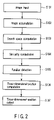
- FIG. 2 is a flowchart illustrating the operation of the first embodiment
- FIG. 3 is a view useful in explaining a method for reconstructing three-dimensional information utilizing stereoscopic views
- FIG. 4 is a view showing the relationship between the epipolar line and parallax
- FIG. 5 is a view illustrating windows used to compute the degree of similarity between projected points
- FIG. 6 is a view illustrating the relationship between a stereo camera and reference plane employed in the first embodiment
- FIG. 7 is a view illustrating (x-y-d) three-dimensional space V and parallax search range employed in the first embodiment
- FIG. 8 is a view illustrating windows used to compute the degree of similarity in the first embodiment
- FIG. 9 is a view illustrating an overlapping state of windows used to compute the degree of similarity in the first embodiment
- FIG. 10 is a flowchart illustrating the operation of a similarity computation section employed in the first embodiment
- FIG. 11 is a view illustrating an example of a parallax search range employed in the first embodiment
- FIG. 12 is a view illustrating the relationship between the position of a projected point and the parallax search range, employed in the first embodiment
- FIG. 13 is a view useful in explaining two epipolar lines appearing on a reference plane employed in the first embodiment
- FIG. 14 is a block diagram illustrating the configuration of a three-dimensional-information reconstructing apparatus according to a second embodiment of the invention.
- FIG. 15 is a view illustrating the relationship between a stereo camera and a pedestrian, used in the second embodiment
- FIG. 16 is a view illustrating the relationship between points in three-dimensional space, which have the same parallax
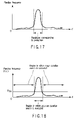
- FIG. 17 is a graph illustrating an example of a parallax frequency distribution in the second embodiment
- FIG. 18 is a graph illustrating the relationship between the parallax frequency distribution and the parallax search estimation value
- FIG. 19 is a flowchart illustrating the operation of a similarity computation section employed in the second embodiment
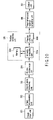
- FIG. 20 is a block diagram illustrating the configuration of a three-dimensional-information reconstructing apparatus according to a third embodiment of the invention.
- FIG. 21 is a flowchart illustrating the operation of the third embodiment
- FIG. 22 is a block diagram illustrating the configuration of a three-dimensional-information reconstructing apparatus according to a fourth embodiment of the invention.
- FIG. 23 is a flowchart illustrating the operation of the fourth embodiment
- FIG. 24 is a view useful in explaining a method employed in the fourth embodiment for acquiring the sum of brightness levels in an arbitrary image region.
- FIG. 25 is a view useful in explaining another method employed in the fourth embodiment for acquiring the sum of brightness levels in an arbitrary image region.
- a three-dimensional-information reconstructing apparatus, method and program that realize high-speed reconstruction of three-dimensional information are provided.
- the degree of similarity between corresponding projected points on a new reference image and a new image is computed in relation to an arbitrary parallax candidate, using the sum of products of the brightness levels of corresponding pixels on a reference image and another image, which is previously computed and stored in a memory.
- a three-dimensional-information reconstructing apparatus, method and program that realize high-speed reconstruction of three-dimensional information by setting the accuracy of a parallax search based on three-dimensional information reconstructed from already acquired images are also provided.
- the sum of products of the brightness levels of corresponding pixels on a reference image and another image is beforehand computed and stored in a memory, and is utilized to compute, for an arbitrary parallax candidate, the degree of similarity between corresponding projected points on a new reference image and a new image.
- FIG. 3 a brief description will be given of a three-dimensional-information reconstructing method based on stereoscopic views.
- two cameras are positioned at the right and left sides to capture an object in three-dimensional space as shown in (a) of FIG. 3 , and the position (X, Y, Z) of the object is determined from image information acquired from the right and left cameras.
- each point in the object is projected onto different points of the right and left images captured from the two cameras as shown in (b) of FIG. 3 .
- Such a displacement in projected point between images is called a parallax.
- the parallax between projected points on the right and left images varies, depending upon the position of a point in three-dimensional space to be projected.
- a certain projected point corresponding to a projected point on one (i.e., reference image) of the images is searched for on the other image, and the parallax between these projected points is computed, a position (X, Y, Z) in three-dimensional space corresponding to the certain projected point on the reference image can be acquired utilizing the principle of triangular surveying. Similarly, positions in three-dimensional space corresponding to all projected points on the reference image are computed. As a result, an object in three-dimensional space is reconstructed.
- the projected point P′ on the other (right) image corresponding to the projected point P on the reference (left) image can be detected by computing the degree of similarity between the projected point P and each projected point on the epipolar line on the right image, and detecting the point on the epipolar line that has the maximum similarity with respect to the projected point p. More specifically, as shown in FIG. 5 , the degree of similarity is detected between the brightness of each pixel contained in a certain range (window) including the projected point P as the center of the window, and the brightness of each pixel contained in a window including each point on the epipolar line as the center of the window. The projected point P′ that has the maximum similarity is determined to be the corresponding projected point.
- FIG. 1 is a block diagram illustrating a three-dimensional-information reconstructing apparatus according to a first embodiment of the invention.
- the three-dimensional-information reconstructing apparatus comprises an image input unit 101 , image accumulation unit 102 , search space computing unit 103 , parallax computing unit 104 , three-dimensional-position computing unit 105 and output unit 106 .
- the parallax computing unit 104 comprises a similarity computing unit 104 a , parallax detection unit 104 b and memory 104 c.
- the image input unit 101 is formed of a plurality of cameras having a function for capturing an object existing in three-dimensional space.
- the image input unit 101 is formed of two cameras located on the right and left sides in parallel with each other, as shown in FIG. 6 .
- the central point of each of the lenses of the right and left cameras is set as the origin of the three-dimensional coordinate system.
- the epipolar line connecting the central points of the lenses to each other is set as X-axis.
- the epipolar line perpendicular to X-axis is set as Y-axis (the downward direction is set as the positive direction).
- the direction of the optical axis of the cameras is set as Z-axis.
- the positions of the left and right cameras can be expressed as ( ⁇ B, 0, 0) and (B, 0, 0), respectively.
- the image accumulation unit 102 has a function for storing image data acquired by the image input unit 101 , and is formed of a semiconductor memory, hard disk, CD-R, CD-RW, DVD-R, or DVD-RAM, etc.
- the search space computing unit 103 has a function for computing a parallax search range from a plurality of image data items accumulated in the image accumulation unit 102 .
- the parallax computing unit 104 comprises a similarity computing unit 104 a , parallax detection unit 104 b and memory 104 c .
- the similarity computing unit 104 a has a function for computing, in relation to each of all parallax candidates d, the degree of similarity between a projected point (x, y) on a left image sent from a left (first) camera, and the corresponding projected point (x′, y′) on a right image sent from a right (second) camera.
- the left image will hereinafter be referred to as “the reference image”, and the right image will hereinafter referred to “the other image”.
- the parallax detection unit 104 b has a function for detecting the parallax between a projected point on the reference image and the corresponding projected point on the other image, based on the degree of similarity therebetween computed by the similarity computing unit 104 a .
- the memory 104 c has a function for storing the sum of the products of the brightness levels of pairs of corresponding pixels on the reference image and the other image.
- the three-dimensional-position computing unit 105 has a function for computing the position of, for example, an object in three-dimensional space captured by the cameras, based on the parallax computed by the parallax computing unit 104 .
- the output unit 106 has a function for displaying the three-dimensional position of, for example, an object computed by the three-dimensional-position computing unit 105 .
- the unit 106 is formed of, for example, a CRT display or liquid crystal display.
- FIG. 2 is a flowchart illustrating the operation.
- the image input unit 101 acquires images of, for example, a three-dimensional object using the right and left cameras, and sends them to the image accumulation unit 102 (Step S 101 ).
- the images sent from the image input unit 101 are accumulated in the image accumulation unit 102 (step S 102 ).
- the search space computing unit 103 utilizes the fact that the three-dimensional object exists on or above the reference plane, to compute the parallax search range from the image data stored in the image accumulation unit 102 (step S 103 ). A method for determining the parallax search range using the right and left cameras will now be described.
- the upper space indicated by expression (6) is the space where the camera exists.
- FIG. 7B is a cross section of (x-y-d) three-dimensional space V taken along the (y-d) plane in FIG. 7A . In FIG. 7B , the hatched portion satisfies expression (6).
- the search space computing unit 103 supplies the parallax computing unit 104 with parallax search space information determined as the above.
- the similarity computing unit 104 a computes, in relation to each of all parallax candidates d, the degree of similarity between a projected point (x, y) on the reference image, and a projected point (x′, y′) on the other image corresponding to the projected point (x, y) (step S 104 ).
- ⁇ d is set to a low value, a detailed parallax search is enabled. If ⁇ d is set to 1, the parallax can be determined in units of pixels.
- S 1 is the sum of the brightness levels f of the pixels included in each window on the reference image
- S 2 is the sum of the brightness levels g of the pixels included in each window on the other image
- S 11 is the sum of the squares of the brightness levels f of the pixels included in each window on the reference image
- S 12 is the sum of the squares of the brightness levels g of the pixels included in each window on the other image.
- S 12 indicates the sum of the products of the brightness levels of pairs of corresponding pixels included in windows on the reference image and the other image, therefore depends upon not only the brightness of each pixel but also the parallax candidate d.
- Equation (11) M (x, y, d) used in equation (11) is defined as follows:
- M (x, y, d) indicates the sum of the products of the brightness levels of pairs of corresponding pixels included in windows on the reference image and the other image, acquired with x fixed and y varied.
- the similarity computing unit 104 a stores, in the memory 104 c , M (x ⁇ w, y, d) to M (x ⁇ 1+w, y, d) acquired when S 12 (x ⁇ 1, y, d) is computed, it can acquire S 12 (x, y, d) simply by newly calculating M (x+w, y, d) and substituting this value and the values stored in the memory 104 c into equation (13).
- efficient computation is realized.
- the similarity computing unit 104 a stores, in the memory 104 c , already computed M (x ⁇ 1 ⁇ w, y, d) and S 12 (x ⁇ 1, y, d), it can also acquire S 12 (x, y, d) simply by newly calculating M (x+w, y, d) and substituting this value and the values stored in the memory 104 c into equation (14).
- the similarity computing unit 104 a stores already computed M (x ⁇ w, y, d) and S 12 (x, y, d) in the memory 104 c , it can acquire S 12 (x+1, y, d) corresponding to a projected point (x+1, y) adjacent by one pixel to the projected point (x, y) simply by newly calculating M (x+1+w, y, d). Further, by substituting M (x+1+w, y, d) and the values stored in the memory 104 c into equation (10), the normalized cross-correlation C (x+1, y, d) corresponding to the projected point (x+1, y) related to the parallax candidate d can be acquired.
- the similarity computing unit 104 a stores S 12 (x, y, d) and M (x+w, y, d) in the memory 104 c whenever it computes S 12 (x, y, d)
- the once-computed sum of products of the brightness levels of pixels can be utilized to thereby enhance the efficiency of similarity computation.
- step S 201 S 1 , S 2 , S 11 and S 22 that can be acquired regardless of the parallax candidate d are computed and stored in the memory 104 c.
- S 12 (x, y, d) is computed. If S 12 (x ⁇ 1, y, d) and M (x ⁇ 1 ⁇ w, y, d) are already stored in the memory 104 c as described above, only M (x+w, y, d) is newly computed, and this value and the values stored in the memory 104 c are substituted into equation (14) to acquire S 12 (x, y, d).
- step S 206 S 1 , S 2 , S 11 , S 22 and S 12 (x, y, d) are substituted into equation (10) to acquire the normalized cross-correlation C (x, y, d).
- the once-calculated sum of the products of pixels of the windows are stored in the memory 104 c and used to compute the normalized cross-correlation, resulting in an increase in the efficiency of similarity computation.
- the projected point on the reference image is shifted by one pixel from (x, y) to, for example, (x+1, y).
- step S 208 it is determined whether the new projected point (x+1, y) on the reference image is included in a search space that satisfies expression (6) acquired by the search space computing unit 103 . Namely, if the parallax candidate is represented by d, the hatched region in FIG. 11 is a search space ⁇ . Therefore, if the projected point (x+1, y) on the reference image exists outside the search space ⁇ as shown in FIG. 12 , the process proceeds to step S 209 . If, on the other hand, it exists within the search space ⁇ as shown in FIG. 12 , the process returns to step S 204 .
- step S 204 the normalized cross-correlation C corresponding to a projected point on the reference image shifted by one pixel from the projected point (x+1, y) is computed.
- the computation steps S 204 to S 208 are iterated in the search space ⁇ in which the parallax candidate is d.
- step S 209 it is determined whether the cross-correlation values C corresponding to all projected points on the reference image have been computed in relation to the parallax candidate d. If the answer at step S 209 is Yes, the process proceeds to step S 210 , whereas if the answer at step S 209 is No, the process proceeds to step S 207 .
- step S 210 it is determined whether processes corresponding to all parallax candidates have been completed. Namely, it is determined whether the value of the parallax candidate d reaches a preset maximum parallax candidate value dMAX. If it does not reach the maximum value dMAX, i.e., if all parallax candidates have not yet been processed, the process proceeds to step S 211 . In contrast, if it does reach the maximum value dMAX, i.e., if all parallax candidates have been processed, the process is finished.
- the normalized cross-correlation C between projected points corresponding to the new parallax candidate is computed in the same procedure as the above.
- the computation processes steps S 203 to S 211 are performed for all parallax candidates.
- the similarity computing unit 104 a computes the normalized cross-correlation values C corresponding to all parallax candidates d in accordance with the above-described flowchart, it is not necessary, concerning adjacent projected points on the reference image, to compute in a duplicate manner the sum of products of the brightness levels of pixels in overlapping portions of windows between the reference image and the other image. As a result, highly efficient high-speed similarity computation can be realized. Further, since no similarity computation is performed for projected points outside a parallax search range on the reference image determined by the search-space computing unit 103 , high-speed processing can be realized.
- the parallax detection unit 104 b determines a parallax D corresponding to a projected point (x, y) on the reference image, using a degree of similarity computed for the parallax candidate by the similarity computing unit 104 a (step S 105 ). It is sufficient if the parallax D corresponding to the projected point (x, y) on the reference image is set to a parallax candidate d, at which the normalized cross-correlation C (x, y, d) acquired by the similarity computing unit 104 a is maximum. Namely, based on the normalized cross-correlation C (x, y, d), the parallax D can be given by the following equation:
- the parallax D corresponding to each projected point on the reference image and acquired by equation (15) is sent to the three-dimensional-position computing unit 105 .
- the three-dimensional-position computing unit 105 Based on the parallax D corresponding to each projected point on the reference image and acquired by the parallax computing unit 104 , the three-dimensional-position computing unit 105 computes the position (X, Y, Z), in three-dimensional space, of an object whose image appears on the reference image (step S 106 ).
- the position (X, Y, Z) in three-dimensional space can be acquired from equation (2), using the projected point (x, y) and the parallax D computed by the parallax computing unit 104 .
- the output unit 106 outputs the three-dimensional position of each point on the reference image, acquired by the three-dimensional-position computing unit 105 (step S 107 ).
- the output unit 106 comprises, for example, a CRT display or liquid crystal display.
- the sum of products of the brightness levels of pixels corresponding to the projected points is stored in the memory 104 c . More specifically, the pixels are contained in a window on the reference image including the arbitrary projected point and in a window on the other image including the projected point that corresponds to the arbitrary projected point. The stored sum is utilized to newly compute the degree of similarity between another projected point on the reference image and a projected point on the other image corresponding thereto, which enables a high-speed parallax search.
- the degree of similarity may be expressed as the sum D sad of the absolute values of the brightness differences of corresponding pixels on the reference image and the other image, which is given by
- the degree of similarity may be expressed as the sum D sad of the squares of the brightness differences, which is given by
- the sum of products of the brightness levels of pixels corresponding to the projected points is stored in the memory 104 c .
- the stored sum is utilized to newly compute the degree of similarity between another projected point on the reference image and a projected point on the other image corresponding thereto, thereby making it unnecessary to again compute the sum of products of the brightness levels of corresponding pixels included in the overlapping portions of the windows.
- efficient similarity computation is realized.
- cameras positioned at the right and left sides in parallel with each other are used to acquire right and left images
- these images can also be acquired by a single camera.
- the single camera is positioned at position ( ⁇ B, 0, 0) in FIG. 6 to acquire the left image (reference image), and is then positioned at position (B, 0, 0) in FIG. 6 to acquire the right image.
- a single camera can provide images similar to those provided by two cameras.
- this equation can be acquired from images picked up, and the search range for the parallax D can be determined from the equation.
- the parallax search space is given by ⁇ X+ ⁇ Y+yZ ⁇ 1 (21)
- the equation for the reference plane can be acquired from images captured by cameras. Therefore, even if, for example, a plurality of cameras used for capturing are moved by external vibration and hence the reference plane is always varied, the parallax search range can be accurately detected.
- the reference plane is set as a flat plane perpendicular to the Y-axis, it does not always have to be a flat plane. Even if the reference plane is a curved plane, high-speed three-dimensional information reconstruction can be realized by the same method as the above.
- the three-dimensional-information reconstructing apparatus can be realized by, for example, using a versatile computer as basic hardware.
- the search space computing unit 103 , similarity computing unit 104 a , parallax detection unit 104 b and three-dimensional-position computing unit 105 can be realized by causing the processor installed in the computer to execute programs.
- the three-dimensional-information reconstructing apparatus may be realized by pre-installing the programs in the computer, or by storing them in a recording medium, such as a CD-ROM, and installing the stored programs in the computer, or by downloading them from a network into the computer.
- the image accumulation unit 102 and memory 104 c can be realized by memory devices installed in the computer, external memory devices, or by storage mediums, such as CD-R, CD-RW, DVD-RAM, DVD-R, etc.
- the similarity computing unit 104 a computes, for each of parallax candidates, the degree of similarity between each projected point included in a search range on a reference image, and the corresponding projected point on another image.
- accurate parallax detection is performed concerning the object, while rough parallax detection is performed concerning the background of the object, thereby reducing the number of computations necessary to detect parallaxes. As a result, high-speed three-dimensional information reconstruction can be realized.
- the parallax between each projected point on the reference image and the corresponding projected point on the other image is acquired, using still image data picked up at a certain time point (t). Subsequently, based on the acquired parallax, the position, in three-dimensional space, of a moving object included in the still image data is detected. After that, when the parallax between each projected point on the reference image and the corresponding projected point on the other image is acquired, using still image data picked up at the next time point (t+1), the parallax is accurately computed in a region including the moving object, which is already detected from past still image data, and the parallax in the other region is roughly computed. This enables the parallax related to the moving object to be accurately detected, and enables the number of computations for a parallax search to be reduced, with the result that high-speed reconstruction of three-dimensional information can be realized.
- FIG. 14 is a block diagram illustrating the configuration of a three-dimensional-information reconstructing apparatus according to a second embodiment of the invention.
- the three-dimensional-information reconstructing apparatus of the second embodiment comprises an image input unit 201 , image accumulation unit 202 , search space computing unit 203 , search estimation value computing unit 204 , parallax computing unit 205 , three-dimensional-position computing unit 206 , output unit 207 , etc.
- the parallax computing unit 205 includes a similarity computing unit 205 a , parallax detection unit 205 b and memory 205 c.
- the search estimation value computing unit 204 has a function for detecting the position of an object based on a parallax previously acquired by the parallax computing unit 205 , and determining an estimation value (the accuracy degree of the parallax search) for a parallax search based on the detected position.
- the other elements of the second embodiment are similar to the elements of the first embodiment, therefore no description is given thereof.
- the image input unit 201 captures an object in three-dimensional space at regular time intervals, using two cameras, i.e., right and left cameras, and sends resultant images of the object to the image accumulation unit 202 .
- the images from the image input unit 201 are stored as time-series data in the image accumulation unit 202 .
- the search estimation value computing unit 204 detects the position of the object based on the parallax previously computed by the parallax computing unit 205 , and determines an estimation value for a parallax search based on the detected position.
- FIGS. 15 to 18 a method for determining an estimation value for a parallax search from a previously computed parallax will be described. For facilitating the description, assume that the two cameras capture a pedestrian walking obliquely as shown in FIG. 15 .
- FIG. 17 shows a parallax frequency distribution corresponding to all projected points on the reference image, acquired at the certain time point (t).
- the parallax frequency corresponding to the pedestrian is high. From this parallax frequency distribution, it can be understood that the pedestrian exists at the position corresponding to the high parallax frequency.
- a parallax frequency distribution is determined from parallaxes corresponding to all projected points on the reference image acquired at the previous time point (t). Assume here that the frequency of a parallax d is set as P(d). Further, an appropriate threshold value P TH is set for the parallax frequency P(d) as shown in FIG. 18 . In the range that satisfies the following expression (22), a rough parallax computation is performed, while in the other region, an accurate parallax computation is performed. P ( d ) ⁇ P TH (22)
- the thus-obtained estimation value information for a parallax search is sent to the parallax computing unit 205 . Specifically, it is determined whether each parallax candidate d satisfies expression (22). If each parallax candidate d satisfies expression (22), data “ 1 ” is sent to the parallax computing unit 205 , whereas if it does not satisfy expression (22), data “ 0 ” is sent to the unit 205 .
- the similarity computing unit 205 a computes, in relation to each parallax candidate d, the degree of similarity between a projected point (x, y) on the reference image, and the corresponding projected point (x′, y′) on the other image.
- a description will be given of a method employed in the similarity computing unit 205 a for computing the degree of similarity based on an estimation value K for a parallax search determined by the parallax estimation value computing unit 204 .
- this method assume that the above-described normalized cross-correlation C is used as the degree of similarity. Note that the flowchart of FIG.
- step S 311 the value of the parallax candidate d is reduced or increased based on the estimation value K for a parallax search.
- steps S 301 to S 310 are omitted.
- the steps S 303 to S 311 are executed for all parallax candidates in accordance with the estimation value K for a parallax search.
- the search estimation value computing unit 204 performs an accurate parallax search for parallax candidates corresponding to points in three-dimensional space at which it is very possible that an object exists, and performs a rough parallax search for the other parallax candidates. As a result, the number of computations required for parallax search can be reduced.
- the parallax detection unit 205 b determines a parallax corresponding to each projected point on the reference image, using a degree of similarity corresponding to each parallax candidate and acquired by the similarity computing unit 205 a .
- the parallax D corresponding to a projected point (x, y) on the reference image is determined to be a parallax candidate d at which the normalized cross-correlation C (x, y, d) acquired by the similarity computing unit 205 a is maximum. Namely, based on the normalized cross-correlation C (x, y, d), the parallax D is given by equation (15). It is sufficient if this computation is executed only on the parallax candidates searched for by the similarity computing unit 205 a.
- the parallax computing unit 205 operates as described above.
- the newest parallax information acquired by the parallax computing unit 205 is sent to the three-dimensional-position computing unit 206 and search estimation value computing unit 204 .
- an accurate parallax search is performed in a region at and near the position of an object detected by past still image data, while a rough parallax search is performed in the other region.
- parallaxes corresponding to the object are detected accurately with the number of required computations reduced, resulting in the realization of high-speed three-dimensional-information reconstruction.
- the similarity computing unit 104 a computes the degree of similarity between a projected point (x, y) on the reference image and the corresponding projected point (x′, y′) on the other image, by computing the normalized cross-correlation C (x, y, d) between a window of a predetermined size including the projected point (x, y), and a window of the same size including the corresponding projected point (x′, y′).
- the size of the window is determined based on variation in brightness between pixels contained in a certain range defined with respect to each projected point on the reference image, and the degree of similarity corresponding to each projected point on the reference image is determined using the window.
- FIG. 20 is a block diagram illustrating the configuration of a three-dimensional-information reconstructing apparatus according to the third embodiment.
- the three-dimensional-information reconstructing apparatus of the third embodiment comprises an image input unit 301 , image accumulation unit 302 , search space computing unit 303 , window determination unit 304 , parallax computing unit 305 , three-dimensional-position computing unit 306 and output unit 307 , etc.
- the parallax computing unit 305 comprises a similarity computing unit 305 a , parallax detection unit 305 b and memory 305 c.
- the third embodiment differs from the first embodiment in that the former further comprises the window determination unit 304 .
- the elements in the third embodiment which perform the same operations as those of the elements in the first embodiment, i.e., image input unit 301 , image accumulation unit 302 , search space computing unit 303 , three-dimensional-position computing unit 306 and output unit 307 .
- FIG. 21 is a flowchart illustrating the operation of the apparatus.
- the window determination unit 304 determines the size of a window at step S 404 .
- This window is used to compute the degree-of-similarity C (x, y, d) between a projected point (x, y) on the reference image and the corresponding projected point (x′, y′) on the other image, based on variation in brightness between pixels contained in a certain range defined with respect to the projected point (x, y).
- S 0 (x, y) is the sum of brightness levels in the window, and is given by
- the window determination unit 304 determines the size of the window used to compute a degree-of-similarity C (x, y, d) corresponding to the projected point (x, y). Specifically, the window size is determined by preparing windows of different sizes, and selecting an appropriate one therefrom in accordance with the width of the brightness variation ⁇ (x, y) 2 . For instance, one is selected from windows W 1 , W 2 and W 3 (W 1 >W 2 >W 3 ), using the following expressions (25):
- TH 1 and TH 2 are threshold values related to the preset brightness variation ⁇ (x, y) 2 .
- the window determined by the window determination unit 304 for the projected point (x, y) on the reference image is sent to the parallax computing unit 305 .
- the parallax computing unit 305 firstly, the similarity computing unit 305 a computes, with respect to all parallax candidates d, the degree of similarity between a projected point (x, y) on the reference image and the corresponding projected point (x′, y′) on the other image, using the window determined by the window determination unit 304 (step S 405 ). Subsequently, the parallax detection unit 305 b determines a parallax D corresponding to each projected point on the reference image, using a degree of similarity corresponding to each parallax candidate and acquired by the similarity computing unit 305 a (step S 406 ).
- a window of an appropriate size is set in units of projected points on the reference image, based on brightness variation between pixels included in a certain range defined with respect to each projected point.
- the window is used to relate projected points on the reference image and the other image to each other. As a result, projected points are related to each other more accurately.
- the window determination unit 304 determines the size of a window used to compute a degree-of-similarity C (x, y, d) corresponding to a projected point (x, y) on the reference image, based on brightness variation between pixels contained in a certain range defined with respect to the projected point (x, y).
- the size of the window used to compute a degree-of-similarity C (x, y, d) is adjusted in units of projected points (x, y) on the reference image, based on variation in parallax D in a certain range defined with respect to each projected point (x, y). Furthermore, the adjusted window is used to re-compute the degree-of-similarity C (x, y, d). This process will be described.
- FIG. 22 is a block diagram illustrating the configuration of a three-dimensional-information reconstructing apparatus according to the fourth embodiment.
- the three-dimensional-information reconstructing apparatus of the fourth embodiment comprises an image input unit 401 , image accumulation unit 402 , search space computing unit 403 , window determination unit 404 , parallax computing unit 405 , three-dimensional-position computing unit 406 and output unit 407 , etc.
- the parallax computing unit 405 comprises a similarity computing unit 405 a , parallax detection unit 405 b , memory 405 c and window adjusting unit 405 d.
- the fourth embodiment differs from the third embodiment in that in the former, the parallax computing unit 405 includes the window adjusting unit 405 d .
- the elements in the fourth embodiment which perform the same operations as those of the elements in the third embodiment, i.e., image input unit 401 , image accumulation unit 402 , search space computing unit 403 , window determination unit 404 , three-dimensional-position computing unit 406 and output unit 407 .
- FIG. 23 is a flowchart illustrating the operation of the apparatus.
- the parallax detection unit 405 b determines a parallax D corresponding to a projected point (x, y) on the reference image, using a degree of similarity corresponding to each parallax candidate and acquired by the similarity computing unit 405 a (step S 506 ).
- the determined parallax candidate D corresponding to the projected point (x, y) on the reference image is sent to the window adjusting unit 405 d.
- the window adjusting unit 405 d adjusts the size of the window used to compute a degree-of-similarity C (x, y, d) corresponding to a projected point (x, y) on the reference image, based on the parallax D (x, y) corresponding to the projected point (x, y) and sent from the parallax detection unit 405 b (step S 507 ).
- the window adjusting unit 405 d detects parallax variation in units of projected points (x, y) on the reference image, using the parallax D (x, y) corresponding to each projected point and acquired by the parallax detection unit 405 b . Based on the parallax variation, the window adjusting unit 405 d adjusts the window.
- Parallax variation corresponding to a projected point (x, y) on the reference image is given by the following equation (26) as variance of the parallax D (x, y) in a window of (2w+1) ⁇ (2w+1) that uses the projected point (x, y) as the center of the window:
- the window adjusting unit 405 d determines the size of the window used to compute the degree-of-similarity C (x, y, d) corresponding to the projected point (x, y). Specifically, to determine the window size, a plurality of windows of different sizes are prepared, and an appropriate one is selected therefrom in accordance with the width of the parallax variation ⁇ D (x, y) 2 . For instance, one is selected from windows W 1 , W 2 and W 3 (W 1 >W 2 >W 3 ), using the following expressions (28):
- TH 1 and TH 2 are threshold values related to the preset brightness variation ⁇ (x, y) 2 .
- the window adjusting unit 405 d sends the thus-acquired window corresponding to the projected point (x, y) on the reference image to the similarity computing unit 405 a.
- the similarity computing unit 405 a re-computes, for each of parallax candidates d, the degree-of-similarity C between the projected point (x, y) on the reference image and the corresponding projected point (x′, y′) on the other image (step S 508 ).
- the re-computation of the degree of similarity for each of parallax candidates d is executed, for example, in accordance with the flowchart of FIG. 10 as in the above-described first embodiment.
- the parallax detection unit 405 b re-computes the parallax D (x, y) corresponding to each projected point on the reference image (step S 509 ).
- the three-dimensional-position computing unit 406 computes the position (X, Y, Z), in three-dimensional space, of an object whose image appears in the reference image (step S 510 ).
- the projected points (x, y) on the reference image are appropriately related to the projected points (x′, y′) on the other image, using windows having a size appropriately determined from brightness variation in pixels.
- parallaxes corresponding to the projected points (x, y) on the reference image are acquired.
- parallax variation in a certain range defined with respect to each projected point on the reference image is detected, and a window corresponding to the certain range is adjusted based on this parallax variation.
- the correspondence between the projected points (x, y) on the reference image and the projected points (x′, y′) on the other image is adjusted.
- the projected points can be made to more accurately correspond to each other.
- the window adjusting unit 405 d performs window adjustment only one time, it may again perform window adjustment based on parallaxes detected using the once-adjusted windows. Repetition of parallax detection and window adjustment enables the projected points to be made to more accurately correspond to each other, resulting in more accurate parallax detection.
- the window adjusting unit 405 d may change the configuration of each window based on the parallaxes detected by the parallax detection unit 405 b .
- a plurality of windows of different sizes are prepared beforehand, and parallax variation corresponding to a projected point (x, y) on the reference image is detected in units of windows, using parallaxes acquired by the parallax detection unit 405 b , thereby selecting the window that minimizes the width of parallax variation.
- S D (x, y) is the sum of parallaxes in the window, and is given by
- the window adjusting unit 405 d adjusts not only the window size but also the window configuration, which enables more accurate parallax detection.
- the window adjusting unit 405 d adjusts each window based on the parallax D (x, y) acquired by the parallax detection unit 405 b , it may perform the following. Namely, the parallax D (x, y) is substituted into d in equation (2), thereby acquiring the three-dimensional depth Z (x, y) corresponding to a projected point (x, y) on the reference image, and adjusting the corresponding window based on variation in depth Z (x, y). Variation in depth Z (x, y) is detected by using, instead of D (x, y), the depth Z (x, y) corresponding to the projected point (x, y), in equation (26).
Abstract
Description
where d=x−x′, and d represents a displacement in display position between the corresponding projected points on the right and left images, i.e., a parallax candidate. Further, since the three-dimensional object exists in front of the cameras, the following is established:
Z≧0 (3)
d≧0 (4)
Y≦Y0 (5)
where N is the number of pixels in each window, and N=(2w+1)2. Further, σ1 and σ2 are variances in pixel brightness in the respective windows, and are given by the following equations:
S 12(x,y,d)=M(x−w,y,d)+ . . . +M(x−1+w,y,d)+M(x+w,y,d) (11)
S 12(x−1,y,d)=M(x−1−w,y,d)+M(x−w,y,d)+ . . . +M(x−1+w,y,d) (13)
S 12(x,y,d)=S 12(x−1,y,d)−M(x−1−w,y,d)+M(x+w,y,d) (14)
t{B(a 1 +a 1′)α+2Bβ−Δa 1 }+B(b 1 +b 1′)α+2BFγ−Δb 1=0 (18)
where Δa1=a1−a1′ and Δb1=b1−b1′. The following equation is established regardless of the value of t:
B(a 1 +a 1′)α+2Bβ−Δa 1=0
B(b 1 +b 1′)α+2BFγ−Δb 1=0 (19)
B(a 2 +a 2′)α+2Bβ−Δa 2=0
B(b 2 +b 2′)α+2BFγ−Δb 2=0 (20)
αX+βY+yZ≦1 (21)
P(d)≦P TH (22)
where N is the number of pixels in the window, and expressed by N=(2w+1)2. Further, S0 (x, y) is the sum of brightness levels in the window, and is given by
where TH1 and TH2 are threshold values related to the preset brightness variation σ (x, y)2.
where N is the number of pixels included in the window, and N=(2w+1)2. Further, Sp (x, y) is the sum of parallaxes in the window, and is given by
where TH1 and TH2 are threshold values related to the preset brightness variation σ (x, y)2.
where N is the number of pixels in the window, and expressed by N=(2w+1)2. Further, SD (x, y) is the sum of parallaxes in the window, and is given by
S 1 =F(x 2 ,y 2)+F(x 1 ,y 1)−F(x 1 ,y 2)−F(x 2 ,y 1) (32)
Claims (12)
Applications Claiming Priority (6)
| Application Number | Priority Date | Filing Date | Title |
|---|---|---|---|
| JP2004-232220 | 2004-08-09 | ||
| JP2004232220 | 2004-08-09 | ||
| JP2005005649 | 2005-01-12 | ||
| JP2005-005649 | 2005-01-12 | ||
| JP2005153965A JP2006221603A (en) | 2004-08-09 | 2005-05-26 | Three-dimensional-information reconstructing apparatus, method and program |
| JP2005-153965 | 2005-05-26 |
Publications (2)
| Publication Number | Publication Date |
|---|---|
| US20060050338A1 US20060050338A1 (en) | 2006-03-09 |
| US7720277B2 true US7720277B2 (en) | 2010-05-18 |
Family
ID=35995887
Family Applications (1)
| Application Number | Title | Priority Date | Filing Date |
|---|---|---|---|
| US11/198,215 Active 2027-10-13 US7720277B2 (en) | 2004-08-09 | 2005-08-08 | Three-dimensional-information reconstructing apparatus, method and program |
Country Status (2)
| Country | Link |
|---|---|
| US (1) | US7720277B2 (en) |
| JP (1) | JP2006221603A (en) |
Cited By (50)
| Publication number | Priority date | Publication date | Assignee | Title |
|---|---|---|---|---|
| US20070165910A1 (en) * | 2006-01-17 | 2007-07-19 | Honda Motor Co., Ltd. | Vehicle surroundings monitoring apparatus, method, and program |
| US20090216581A1 (en) * | 2008-02-25 | 2009-08-27 | Carrier Scott R | System and method for managing community assets |
| US20100225735A1 (en) * | 2009-03-09 | 2010-09-09 | Cisco Technology, Inc. | System and method for providing three dimensional imaging in a network environment |
| CN101852609A (en) * | 2010-06-02 | 2010-10-06 | 北京理工大学 | Ground obstacle detection method based on binocular stereo vision of robot |
| US8319819B2 (en) | 2008-03-26 | 2012-11-27 | Cisco Technology, Inc. | Virtual round-table videoconference |
| US8355041B2 (en) | 2008-02-14 | 2013-01-15 | Cisco Technology, Inc. | Telepresence system for 360 degree video conferencing |
| US8390667B2 (en) | 2008-04-15 | 2013-03-05 | Cisco Technology, Inc. | Pop-up PIP for people not in picture |
| USD678320S1 (en) | 2010-12-16 | 2013-03-19 | Cisco Technology, Inc. | Display screen with graphical user interface |
| USD678307S1 (en) | 2010-12-16 | 2013-03-19 | Cisco Technology, Inc. | Display screen with graphical user interface |
| USD678308S1 (en) | 2010-12-16 | 2013-03-19 | Cisco Technology, Inc. | Display screen with graphical user interface |
| USD678894S1 (en) | 2010-12-16 | 2013-03-26 | Cisco Technology, Inc. | Display screen with graphical user interface |
| USD682293S1 (en) | 2010-12-16 | 2013-05-14 | Cisco Technology, Inc. | Display screen with graphical user interface |
| USD682294S1 (en) | 2010-12-16 | 2013-05-14 | Cisco Technology, Inc. | Display screen with graphical user interface |
| USD682864S1 (en) | 2010-12-16 | 2013-05-21 | Cisco Technology, Inc. | Display screen with graphical user interface |
| USD682854S1 (en) | 2010-12-16 | 2013-05-21 | Cisco Technology, Inc. | Display screen for graphical user interface |
| US8472415B2 (en) | 2006-03-06 | 2013-06-25 | Cisco Technology, Inc. | Performance optimization with integrated mobility and MPLS |
| US8542264B2 (en) | 2010-11-18 | 2013-09-24 | Cisco Technology, Inc. | System and method for managing optics in a video environment |
| US8599934B2 (en) | 2010-09-08 | 2013-12-03 | Cisco Technology, Inc. | System and method for skip coding during video conferencing in a network environment |
| US8599865B2 (en) | 2010-10-26 | 2013-12-03 | Cisco Technology, Inc. | System and method for provisioning flows in a mobile network environment |
| US8659637B2 (en) | 2009-03-09 | 2014-02-25 | Cisco Technology, Inc. | System and method for providing three dimensional video conferencing in a network environment |
| US8659639B2 (en) | 2009-05-29 | 2014-02-25 | Cisco Technology, Inc. | System and method for extending communications between participants in a conferencing environment |
| US8670019B2 (en) | 2011-04-28 | 2014-03-11 | Cisco Technology, Inc. | System and method for providing enhanced eye gaze in a video conferencing environment |
| US8682087B2 (en) | 2011-12-19 | 2014-03-25 | Cisco Technology, Inc. | System and method for depth-guided image filtering in a video conference environment |
| US8694658B2 (en) | 2008-09-19 | 2014-04-08 | Cisco Technology, Inc. | System and method for enabling communication sessions in a network environment |
| US8692862B2 (en) | 2011-02-28 | 2014-04-08 | Cisco Technology, Inc. | System and method for selection of video data in a video conference environment |
| US8699457B2 (en) | 2010-11-03 | 2014-04-15 | Cisco Technology, Inc. | System and method for managing flows in a mobile network environment |
| US8723914B2 (en) | 2010-11-19 | 2014-05-13 | Cisco Technology, Inc. | System and method for providing enhanced video processing in a network environment |
| US8730297B2 (en) | 2010-11-15 | 2014-05-20 | Cisco Technology, Inc. | System and method for providing camera functions in a video environment |
| US8786631B1 (en) | 2011-04-30 | 2014-07-22 | Cisco Technology, Inc. | System and method for transferring transparency information in a video environment |
| US8797377B2 (en) | 2008-02-14 | 2014-08-05 | Cisco Technology, Inc. | Method and system for videoconference configuration |
| US8823776B2 (en) | 2010-05-20 | 2014-09-02 | Cisco Technology, Inc. | Implementing selective image enhancement |
| US8896655B2 (en) | 2010-08-31 | 2014-11-25 | Cisco Technology, Inc. | System and method for providing depth adaptive video conferencing |
| US8902244B2 (en) | 2010-11-15 | 2014-12-02 | Cisco Technology, Inc. | System and method for providing enhanced graphics in a video environment |
| US8934026B2 (en) | 2011-05-12 | 2015-01-13 | Cisco Technology, Inc. | System and method for video coding in a dynamic environment |
| US8947493B2 (en) | 2011-11-16 | 2015-02-03 | Cisco Technology, Inc. | System and method for alerting a participant in a video conference |
| US9082297B2 (en) | 2009-08-11 | 2015-07-14 | Cisco Technology, Inc. | System and method for verifying parameters in an audiovisual environment |
| US9111138B2 (en) | 2010-11-30 | 2015-08-18 | Cisco Technology, Inc. | System and method for gesture interface control |
| US9143725B2 (en) | 2010-11-15 | 2015-09-22 | Cisco Technology, Inc. | System and method for providing enhanced graphics in a video environment |
| US9225916B2 (en) | 2010-03-18 | 2015-12-29 | Cisco Technology, Inc. | System and method for enhancing video images in a conferencing environment |
| US9292927B2 (en) * | 2012-12-27 | 2016-03-22 | Intel Corporation | Adaptive support windows for stereoscopic image correlation |
| US9313452B2 (en) | 2010-05-17 | 2016-04-12 | Cisco Technology, Inc. | System and method for providing retracting optics in a video conferencing environment |
| US9338394B2 (en) | 2010-11-15 | 2016-05-10 | Cisco Technology, Inc. | System and method for providing enhanced audio in a video environment |
| US20170064286A1 (en) * | 2015-08-24 | 2017-03-02 | Denso Corporation | Parallax detection device |
| US9681154B2 (en) | 2012-12-06 | 2017-06-13 | Patent Capital Group | System and method for depth-guided filtering in a video conference environment |
| US9843621B2 (en) | 2013-05-17 | 2017-12-12 | Cisco Technology, Inc. | Calendaring activities based on communication processing |
| US10129523B2 (en) | 2016-06-22 | 2018-11-13 | Microsoft Technology Licensing, Llc | Depth-aware reprojection |
| CN109318890A (en) * | 2018-06-29 | 2019-02-12 | 北京理工大学 | A kind of unmanned vehicle dynamic obstacle avoidance method based on dynamic window and barrier potential energy field |
| US10237531B2 (en) | 2016-06-22 | 2019-03-19 | Microsoft Technology Licensing, Llc | Discontinuity-aware reprojection |
| US10823950B2 (en) * | 2016-01-07 | 2020-11-03 | Digital Surigcals PTE. LTD. | Camera system with balanced monocular cues for use in digital stereo microscopes |
| US20220026698A1 (en) * | 2020-07-24 | 2022-01-27 | United Scope LLC | Digital microscopy system and graphical user interface |
Families Citing this family (24)
| Publication number | Priority date | Publication date | Assignee | Title |
|---|---|---|---|---|
| JPS5990718A (en) * | 1982-11-15 | 1984-05-25 | Mitsubishi Electric Corp | Control device for intake valve of engine |
| JP2006221603A (en) * | 2004-08-09 | 2006-08-24 | Toshiba Corp | Three-dimensional-information reconstructing apparatus, method and program |
| JP4856611B2 (en) * | 2007-10-29 | 2012-01-18 | 富士重工業株式会社 | Object detection device |
| JP5172314B2 (en) * | 2007-12-14 | 2013-03-27 | 日立オートモティブシステムズ株式会社 | Stereo camera device |
| WO2009097552A1 (en) * | 2008-02-01 | 2009-08-06 | Omnivision Cdm Optics, Inc. | Image data fusion systems and methods |
| JP5071865B2 (en) * | 2008-06-03 | 2012-11-14 | 富士フイルム株式会社 | Distance measuring device, method and program |
| JP5071866B2 (en) * | 2008-06-03 | 2012-11-14 | 富士フイルム株式会社 | Distance measuring device, method and program |
| JP2010154461A (en) * | 2008-12-26 | 2010-07-08 | Samsung Techwin Co Ltd | Projection image converter and projector device |
| JP2011013064A (en) * | 2009-07-01 | 2011-01-20 | Nikon Corp | Position detection device |
| US8684531B2 (en) * | 2009-12-28 | 2014-04-01 | Vision3D Technologies, Llc | Stereoscopic display device projecting parallax image and adjusting amount of parallax |
| JP5450330B2 (en) * | 2010-09-16 | 2014-03-26 | 株式会社ジャパンディスプレイ | Image processing apparatus and method, and stereoscopic image display apparatus |
| JP5481337B2 (en) * | 2010-09-24 | 2014-04-23 | 株式会社東芝 | Image processing device |
| US9049423B2 (en) * | 2010-12-01 | 2015-06-02 | Qualcomm Incorporated | Zero disparity plane for feedback-based three-dimensional video |
| US9087375B2 (en) * | 2011-03-28 | 2015-07-21 | Sony Corporation | Image processing device, image processing method, and program |
| JP5158223B2 (en) * | 2011-04-06 | 2013-03-06 | カシオ計算機株式会社 | 3D modeling apparatus, 3D modeling method, and program |
| US8729653B2 (en) | 2011-10-26 | 2014-05-20 | Omnivision Technologies, Inc. | Integrated die-level cameras and methods of manufacturing the same |
| JP2013143753A (en) * | 2012-01-12 | 2013-07-22 | Olympus Corp | Imaging apparatus |
| JP5957359B2 (en) * | 2012-10-19 | 2016-07-27 | 日立オートモティブシステムズ株式会社 | Stereo image processing apparatus and stereo image processing method |
| JP6274557B2 (en) * | 2013-02-18 | 2018-02-07 | 株式会社リコー | Moving surface information detection apparatus, moving body device control system using the same, and moving surface information detection program |
| JP6202367B2 (en) * | 2013-05-14 | 2017-09-27 | 株式会社リコー | Image processing device, distance measurement device, mobile device control system, mobile device, and image processing program |
| US9756312B2 (en) | 2014-05-01 | 2017-09-05 | Ecole polytechnique fédérale de Lausanne (EPFL) | Hardware-oriented dynamically adaptive disparity estimation algorithm and its real-time hardware |
| CN108307170B (en) * | 2017-12-22 | 2019-09-10 | 宁波大学 | A kind of stereo-picture method for relocating |
| JP2021192177A (en) * | 2020-06-05 | 2021-12-16 | 日立Astemo株式会社 | Arithmetic device, and parallax search method |
| JP2021192174A (en) * | 2020-06-05 | 2021-12-16 | 日立Astemo株式会社 | Arithmetic device, and parallax calculation method |
Citations (27)
| Publication number | Priority date | Publication date | Assignee | Title |
|---|---|---|---|---|
| US4924506A (en) * | 1986-07-22 | 1990-05-08 | Schlumberger Systems & Services, Inc. | Method for directly measuring area and volume using binocular stereo vision |
| JPH08178795A (en) | 1994-12-20 | 1996-07-12 | Nec Corp | Lcd panel detect inspection instrument |
| US5825915A (en) * | 1995-09-12 | 1998-10-20 | Matsushita Electric Industrial Co., Ltd. | Object detecting apparatus in which the position of a planar object is estimated by using hough transform |
| US5910817A (en) * | 1995-05-18 | 1999-06-08 | Omron Corporation | Object observing method and device |
| JPH11161792A (en) | 1997-11-26 | 1999-06-18 | Toshiba Corp | Three-dimensional information restoration device/method |
| US5956418A (en) * | 1996-12-10 | 1999-09-21 | Medsim Ltd. | Method of mosaicing ultrasonic volumes for visual simulation |
| JPH11264724A (en) | 1998-03-18 | 1999-09-28 | Sony Corp | Device and method for processing image, and medium provided |
| US6141440A (en) * | 1998-06-04 | 2000-10-31 | Canon Kabushiki Kaisha | Disparity measurement with variably sized interrogation regions |
| US6201541B1 (en) * | 1997-12-11 | 2001-03-13 | Cognitens, Ltd. | System and method for “Stitching” a plurality of reconstructions of three-dimensional surface features of object(s) in a scene defined relative to respective coordinate systems to relate them to a common coordinate system |
| US6215898B1 (en) * | 1997-04-15 | 2001-04-10 | Interval Research Corporation | Data processing system and method |
| JP2001194126A (en) | 2000-01-14 | 2001-07-19 | Sony Corp | Apparatus and method for measuring three-dimensional shape and program providing medium |
| US6269175B1 (en) * | 1998-08-28 | 2001-07-31 | Sarnoff Corporation | Method and apparatus for enhancing regions of aligned images using flow estimation |
| US20020024516A1 (en) * | 2000-05-03 | 2002-02-28 | Qian Chen | Three-dimensional modeling and based on photographic images |
| JP2002163639A (en) | 2000-11-28 | 2002-06-07 | Toshiba Corp | Device and method for restoring three-dimensional information |
| JP2002358595A (en) | 2001-06-01 | 2002-12-13 | Mitsubishi Electric Corp | Instrument and method for measuring road traffic stream |
| US6519358B1 (en) * | 1998-10-07 | 2003-02-11 | Sony Corporation | Parallax calculating apparatus, distance calculating apparatus, methods of the same, and information providing media |
| US6606406B1 (en) * | 2000-05-04 | 2003-08-12 | Microsoft Corporation | System and method for progressive stereo matching of digital images |
| US6658149B1 (en) * | 1999-01-07 | 2003-12-02 | Nippon Telegraph & Telephone Corporation | Scheme for identifying gray-scale image |
| US6677941B2 (en) * | 2000-08-05 | 2004-01-13 | American Gnc Corporation | Three-dimensional relative positioning and tracking using LDRI |
| US20040136567A1 (en) * | 2002-10-22 | 2004-07-15 | Billinghurst Mark N. | Tracking a surface in a 3-dimensional scene using natural visual features of the surface |
| US6906620B2 (en) | 2002-08-28 | 2005-06-14 | Kabushiki Kaisha Toshiba | Obstacle detection device and method therefor |
| US20050196034A1 (en) * | 1999-09-09 | 2005-09-08 | Kabushiki Kaisha Toshiba | Obstacle detection system and method therefor |
| US20060050338A1 (en) * | 2004-08-09 | 2006-03-09 | Hiroshi Hattori | Three-dimensional-information reconstructing apparatus, method and program |
| US7046822B1 (en) * | 1999-06-11 | 2006-05-16 | Daimlerchrysler Ag | Method of detecting objects within a wide range of a road vehicle |
| US7103212B2 (en) * | 2002-11-22 | 2006-09-05 | Strider Labs, Inc. | Acquisition of three-dimensional images by an active stereo technique using locally unique patterns |
| US20080002878A1 (en) * | 2006-06-28 | 2008-01-03 | Somasundaram Meiyappan | Method For Fast Stereo Matching Of Images |
| US20080239116A1 (en) * | 2007-03-27 | 2008-10-02 | Micron Technology, Inc. | Method and apparatus for automatic linear shift parallax correction for multi-array image systems |
-
2005
- 2005-05-26 JP JP2005153965A patent/JP2006221603A/en active Pending
- 2005-08-08 US US11/198,215 patent/US7720277B2/en active Active
Patent Citations (30)
| Publication number | Priority date | Publication date | Assignee | Title |
|---|---|---|---|---|
| US4924506A (en) * | 1986-07-22 | 1990-05-08 | Schlumberger Systems & Services, Inc. | Method for directly measuring area and volume using binocular stereo vision |
| JPH08178795A (en) | 1994-12-20 | 1996-07-12 | Nec Corp | Lcd panel detect inspection instrument |
| US5910817A (en) * | 1995-05-18 | 1999-06-08 | Omron Corporation | Object observing method and device |
| US5825915A (en) * | 1995-09-12 | 1998-10-20 | Matsushita Electric Industrial Co., Ltd. | Object detecting apparatus in which the position of a planar object is estimated by using hough transform |
| US5956418A (en) * | 1996-12-10 | 1999-09-21 | Medsim Ltd. | Method of mosaicing ultrasonic volumes for visual simulation |
| US6215898B1 (en) * | 1997-04-15 | 2001-04-10 | Interval Research Corporation | Data processing system and method |
| JPH11161792A (en) | 1997-11-26 | 1999-06-18 | Toshiba Corp | Three-dimensional information restoration device/method |
| US6201541B1 (en) * | 1997-12-11 | 2001-03-13 | Cognitens, Ltd. | System and method for “Stitching” a plurality of reconstructions of three-dimensional surface features of object(s) in a scene defined relative to respective coordinate systems to relate them to a common coordinate system |
| JPH11264724A (en) | 1998-03-18 | 1999-09-28 | Sony Corp | Device and method for processing image, and medium provided |
| US6141440A (en) * | 1998-06-04 | 2000-10-31 | Canon Kabushiki Kaisha | Disparity measurement with variably sized interrogation regions |
| US20030190072A1 (en) * | 1998-08-28 | 2003-10-09 | Sean Adkins | Method and apparatus for processing images |
| US6269175B1 (en) * | 1998-08-28 | 2001-07-31 | Sarnoff Corporation | Method and apparatus for enhancing regions of aligned images using flow estimation |
| US20010019621A1 (en) * | 1998-08-28 | 2001-09-06 | Hanna Keith James | Method and apparatus for processing images |
| US20010036307A1 (en) * | 1998-08-28 | 2001-11-01 | Hanna Keith James | Method and apparatus for processing images |
| US6519358B1 (en) * | 1998-10-07 | 2003-02-11 | Sony Corporation | Parallax calculating apparatus, distance calculating apparatus, methods of the same, and information providing media |
| US6658149B1 (en) * | 1999-01-07 | 2003-12-02 | Nippon Telegraph & Telephone Corporation | Scheme for identifying gray-scale image |
| US7046822B1 (en) * | 1999-06-11 | 2006-05-16 | Daimlerchrysler Ag | Method of detecting objects within a wide range of a road vehicle |
| US20050196034A1 (en) * | 1999-09-09 | 2005-09-08 | Kabushiki Kaisha Toshiba | Obstacle detection system and method therefor |
| JP2001194126A (en) | 2000-01-14 | 2001-07-19 | Sony Corp | Apparatus and method for measuring three-dimensional shape and program providing medium |
| US20020024516A1 (en) * | 2000-05-03 | 2002-02-28 | Qian Chen | Three-dimensional modeling and based on photographic images |
| US6606406B1 (en) * | 2000-05-04 | 2003-08-12 | Microsoft Corporation | System and method for progressive stereo matching of digital images |
| US6677941B2 (en) * | 2000-08-05 | 2004-01-13 | American Gnc Corporation | Three-dimensional relative positioning and tracking using LDRI |
| JP2002163639A (en) | 2000-11-28 | 2002-06-07 | Toshiba Corp | Device and method for restoring three-dimensional information |
| JP2002358595A (en) | 2001-06-01 | 2002-12-13 | Mitsubishi Electric Corp | Instrument and method for measuring road traffic stream |
| US6906620B2 (en) | 2002-08-28 | 2005-06-14 | Kabushiki Kaisha Toshiba | Obstacle detection device and method therefor |
| US20040136567A1 (en) * | 2002-10-22 | 2004-07-15 | Billinghurst Mark N. | Tracking a surface in a 3-dimensional scene using natural visual features of the surface |
| US7103212B2 (en) * | 2002-11-22 | 2006-09-05 | Strider Labs, Inc. | Acquisition of three-dimensional images by an active stereo technique using locally unique patterns |
| US20060050338A1 (en) * | 2004-08-09 | 2006-03-09 | Hiroshi Hattori | Three-dimensional-information reconstructing apparatus, method and program |
| US20080002878A1 (en) * | 2006-06-28 | 2008-01-03 | Somasundaram Meiyappan | Method For Fast Stereo Matching Of Images |
| US20080239116A1 (en) * | 2007-03-27 | 2008-10-02 | Micron Technology, Inc. | Method and apparatus for automatic linear shift parallax correction for multi-array image systems |
Non-Patent Citations (6)
| Title |
|---|
| Asada, "Understanding of Dynamic Scene", Institute of Electronics, Information and Communications Engineering, pp. 12-15, 2005. |
| Changming Sun, "A Fast Stereo Matching Method", Digital Image Computing: Techniques and Applications, 1997, pp. 95-100. |
| D. Koller, et al. "Using Binocular Stereopsis for Vision-Based Vehicle Control", Intelligent Vehicles Symposium, 1994, pp. 237-242. |
| Noriaki Maru, et al., "Adaptive Disparity Detection in Binocular Vision", Memoir of Japan Robot Association, Japan robot Association, vol. 9, No. 3, Jun. 15, 1991, pp. 27-34. |
| Olga Veksler, "Fast Variable Window for Stereo Correspondence Using Integral Images", Conference on Computer Vision and Pattern Recognition, 2003, vol. I, pp. 556-561. |
| T. Kanade and M. Okutomi, "A Stereo Matching Algorithm with an Adaptive Window: Theory and Experiment," Proceedings of the 1991 IEEE International Conference on Robotics and Automation (ICRA '91), Apr. 1991, pp. 1088-1095. * |
Cited By (55)
| Publication number | Priority date | Publication date | Assignee | Title |
|---|---|---|---|---|
| US20070165910A1 (en) * | 2006-01-17 | 2007-07-19 | Honda Motor Co., Ltd. | Vehicle surroundings monitoring apparatus, method, and program |
| US8175331B2 (en) * | 2006-01-17 | 2012-05-08 | Honda Motor Co., Ltd. | Vehicle surroundings monitoring apparatus, method, and program |
| US8472415B2 (en) | 2006-03-06 | 2013-06-25 | Cisco Technology, Inc. | Performance optimization with integrated mobility and MPLS |
| US8797377B2 (en) | 2008-02-14 | 2014-08-05 | Cisco Technology, Inc. | Method and system for videoconference configuration |
| US8355041B2 (en) | 2008-02-14 | 2013-01-15 | Cisco Technology, Inc. | Telepresence system for 360 degree video conferencing |
| US20090216581A1 (en) * | 2008-02-25 | 2009-08-27 | Carrier Scott R | System and method for managing community assets |
| US8319819B2 (en) | 2008-03-26 | 2012-11-27 | Cisco Technology, Inc. | Virtual round-table videoconference |
| US8390667B2 (en) | 2008-04-15 | 2013-03-05 | Cisco Technology, Inc. | Pop-up PIP for people not in picture |
| US8694658B2 (en) | 2008-09-19 | 2014-04-08 | Cisco Technology, Inc. | System and method for enabling communication sessions in a network environment |
| US20100225735A1 (en) * | 2009-03-09 | 2010-09-09 | Cisco Technology, Inc. | System and method for providing three dimensional imaging in a network environment |
| US8477175B2 (en) | 2009-03-09 | 2013-07-02 | Cisco Technology, Inc. | System and method for providing three dimensional imaging in a network environment |
| US8659637B2 (en) | 2009-03-09 | 2014-02-25 | Cisco Technology, Inc. | System and method for providing three dimensional video conferencing in a network environment |
| US8659639B2 (en) | 2009-05-29 | 2014-02-25 | Cisco Technology, Inc. | System and method for extending communications between participants in a conferencing environment |
| US9204096B2 (en) | 2009-05-29 | 2015-12-01 | Cisco Technology, Inc. | System and method for extending communications between participants in a conferencing environment |
| US9082297B2 (en) | 2009-08-11 | 2015-07-14 | Cisco Technology, Inc. | System and method for verifying parameters in an audiovisual environment |
| US9225916B2 (en) | 2010-03-18 | 2015-12-29 | Cisco Technology, Inc. | System and method for enhancing video images in a conferencing environment |
| US9313452B2 (en) | 2010-05-17 | 2016-04-12 | Cisco Technology, Inc. | System and method for providing retracting optics in a video conferencing environment |
| US8823776B2 (en) | 2010-05-20 | 2014-09-02 | Cisco Technology, Inc. | Implementing selective image enhancement |
| CN101852609B (en) * | 2010-06-02 | 2011-10-19 | 北京理工大学 | Ground obstacle detection method based on binocular stereo vision of robot |
| CN101852609A (en) * | 2010-06-02 | 2010-10-06 | 北京理工大学 | Ground obstacle detection method based on binocular stereo vision of robot |
| US8896655B2 (en) | 2010-08-31 | 2014-11-25 | Cisco Technology, Inc. | System and method for providing depth adaptive video conferencing |
| US8599934B2 (en) | 2010-09-08 | 2013-12-03 | Cisco Technology, Inc. | System and method for skip coding during video conferencing in a network environment |
| US8599865B2 (en) | 2010-10-26 | 2013-12-03 | Cisco Technology, Inc. | System and method for provisioning flows in a mobile network environment |
| US8699457B2 (en) | 2010-11-03 | 2014-04-15 | Cisco Technology, Inc. | System and method for managing flows in a mobile network environment |
| US8902244B2 (en) | 2010-11-15 | 2014-12-02 | Cisco Technology, Inc. | System and method for providing enhanced graphics in a video environment |
| US9143725B2 (en) | 2010-11-15 | 2015-09-22 | Cisco Technology, Inc. | System and method for providing enhanced graphics in a video environment |
| US9338394B2 (en) | 2010-11-15 | 2016-05-10 | Cisco Technology, Inc. | System and method for providing enhanced audio in a video environment |
| US8730297B2 (en) | 2010-11-15 | 2014-05-20 | Cisco Technology, Inc. | System and method for providing camera functions in a video environment |
| US8542264B2 (en) | 2010-11-18 | 2013-09-24 | Cisco Technology, Inc. | System and method for managing optics in a video environment |
| US8723914B2 (en) | 2010-11-19 | 2014-05-13 | Cisco Technology, Inc. | System and method for providing enhanced video processing in a network environment |
| US9111138B2 (en) | 2010-11-30 | 2015-08-18 | Cisco Technology, Inc. | System and method for gesture interface control |
| USD682293S1 (en) | 2010-12-16 | 2013-05-14 | Cisco Technology, Inc. | Display screen with graphical user interface |
| USD678307S1 (en) | 2010-12-16 | 2013-03-19 | Cisco Technology, Inc. | Display screen with graphical user interface |
| USD678320S1 (en) | 2010-12-16 | 2013-03-19 | Cisco Technology, Inc. | Display screen with graphical user interface |
| USD682854S1 (en) | 2010-12-16 | 2013-05-21 | Cisco Technology, Inc. | Display screen for graphical user interface |
| USD682864S1 (en) | 2010-12-16 | 2013-05-21 | Cisco Technology, Inc. | Display screen with graphical user interface |
| USD682294S1 (en) | 2010-12-16 | 2013-05-14 | Cisco Technology, Inc. | Display screen with graphical user interface |
| USD678894S1 (en) | 2010-12-16 | 2013-03-26 | Cisco Technology, Inc. | Display screen with graphical user interface |
| USD678308S1 (en) | 2010-12-16 | 2013-03-19 | Cisco Technology, Inc. | Display screen with graphical user interface |
| US8692862B2 (en) | 2011-02-28 | 2014-04-08 | Cisco Technology, Inc. | System and method for selection of video data in a video conference environment |
| US8670019B2 (en) | 2011-04-28 | 2014-03-11 | Cisco Technology, Inc. | System and method for providing enhanced eye gaze in a video conferencing environment |
| US8786631B1 (en) | 2011-04-30 | 2014-07-22 | Cisco Technology, Inc. | System and method for transferring transparency information in a video environment |
| US8934026B2 (en) | 2011-05-12 | 2015-01-13 | Cisco Technology, Inc. | System and method for video coding in a dynamic environment |
| US8947493B2 (en) | 2011-11-16 | 2015-02-03 | Cisco Technology, Inc. | System and method for alerting a participant in a video conference |
| US8682087B2 (en) | 2011-12-19 | 2014-03-25 | Cisco Technology, Inc. | System and method for depth-guided image filtering in a video conference environment |
| US9681154B2 (en) | 2012-12-06 | 2017-06-13 | Patent Capital Group | System and method for depth-guided filtering in a video conference environment |
| US9292927B2 (en) * | 2012-12-27 | 2016-03-22 | Intel Corporation | Adaptive support windows for stereoscopic image correlation |
| US9843621B2 (en) | 2013-05-17 | 2017-12-12 | Cisco Technology, Inc. | Calendaring activities based on communication processing |
| US20170064286A1 (en) * | 2015-08-24 | 2017-03-02 | Denso Corporation | Parallax detection device |
| US10823950B2 (en) * | 2016-01-07 | 2020-11-03 | Digital Surigcals PTE. LTD. | Camera system with balanced monocular cues for use in digital stereo microscopes |
| US10129523B2 (en) | 2016-06-22 | 2018-11-13 | Microsoft Technology Licensing, Llc | Depth-aware reprojection |
| US10237531B2 (en) | 2016-06-22 | 2019-03-19 | Microsoft Technology Licensing, Llc | Discontinuity-aware reprojection |
| CN109318890A (en) * | 2018-06-29 | 2019-02-12 | 北京理工大学 | A kind of unmanned vehicle dynamic obstacle avoidance method based on dynamic window and barrier potential energy field |
| US20220026698A1 (en) * | 2020-07-24 | 2022-01-27 | United Scope LLC | Digital microscopy system and graphical user interface |
| US11782254B2 (en) * | 2020-07-24 | 2023-10-10 | United Scope LLC | Digital microscopy system and graphical user interface |
Also Published As
| Publication number | Publication date |
|---|---|
| JP2006221603A (en) | 2006-08-24 |
| US20060050338A1 (en) | 2006-03-09 |
Similar Documents
| Publication | Publication Date | Title |
|---|---|---|
| US7720277B2 (en) | Three-dimensional-information reconstructing apparatus, method and program | |
| US7471809B2 (en) | Method, apparatus, and program for processing stereo image | |
| US5383013A (en) | Stereoscopic computer vision system | |
| US9237326B2 (en) | Imaging system and method | |
| US9137518B2 (en) | Method and system for converting 2D image data to stereoscopic image data | |
| US7567703B2 (en) | System for combining multiple disparity maps | |
| US7844077B2 (en) | Location measuring device and method | |
| US6307959B1 (en) | Method and apparatus for estimating scene structure and ego-motion from multiple images of a scene using correlation | |
| US7660434B2 (en) | Obstacle detection apparatus and a method therefor | |
| JP3539788B2 (en) | Image matching method | |
| US9360307B2 (en) | Structured-light based measuring method and system | |
| US9213884B2 (en) | Image processing apparatus, image processing method, and program | |
| US20170151674A1 (en) | Apparatus of recognizing position of mobile robot using search based correlative matching and method thereof | |
| US10529092B2 (en) | Method for reducing matching error in disparity image by information in zoom image | |
| US8873802B2 (en) | Method and apparatus for camera tracking | |
| US10321112B2 (en) | Stereo matching system and method of operating thereof | |
| CN105069804B (en) | Threedimensional model scan rebuilding method based on smart mobile phone | |
| US8538137B2 (en) | Image processing apparatus, information processing system, and image processing method | |
| US20150206307A1 (en) | Visual Perception Matching Cost On Binocular Stereo Images | |
| US6480620B1 (en) | Method of and an apparatus for 3-dimensional structure estimation | |
| US9659372B2 (en) | Video disparity estimate space-time refinement method and codec | |
| JP3786618B2 (en) | Image processing apparatus and method | |
| JP2009282762A (en) | Corresponding point retrieval device | |
| JPH07234111A (en) | Measuring method for three-dimensional object | |
| JPH1096607A (en) | Object detector and plane estimation method |
Legal Events
| Date | Code | Title | Description |
|---|---|---|---|
| AS | Assignment |
Owner name: KABUSHIKI KAISHA TOSHIBA,JAPAN Free format text: ASSIGNMENT OF ASSIGNORS INTEREST;ASSIGNOR:HATTORI, HIROSHI;REEL/FRAME:017220/0972 Effective date: 20051031 Owner name: KABUSHIKI KAISHA TOSHIBA, JAPAN Free format text: ASSIGNMENT OF ASSIGNORS INTEREST;ASSIGNOR:HATTORI, HIROSHI;REEL/FRAME:017220/0972 Effective date: 20051031 |
|
| AS | Assignment |
Owner name: KABUSHIKI KAISHA TOSHIBA, JAPAN Free format text: CORRECTED FORM PTO-1595 TO CORRECT ASSIGNEE'S ADDRESS PREVIOUSLY RECORDED ON REEL 017220 FRAME 0972.;ASSIGNOR:HATTORI, HIROSHI;REEL/FRAME:017688/0061 Effective date: 20051031 Owner name: KABUSHIKI KAISHA TOSHIBA,JAPAN Free format text: CORRECTED FORM PTO-1595 TO CORRECT ASSIGNEE'S ADDRESS PREVIOUSLY RECORDED ON REEL 017220 FRAME 0972;ASSIGNOR:HATTORI, HIROSHI;REEL/FRAME:017688/0061 Effective date: 20051031 |
|
| STCF | Information on status: patent grant |
Free format text: PATENTED CASE |
|
| FEPP | Fee payment procedure |
Free format text: PAYOR NUMBER ASSIGNED (ORIGINAL EVENT CODE: ASPN); ENTITY STATUS OF PATENT OWNER: LARGE ENTITY |
|
| FPAY | Fee payment |
Year of fee payment: 4 |
|
| MAFP | Maintenance fee payment |
Free format text: PAYMENT OF MAINTENANCE FEE, 8TH YEAR, LARGE ENTITY (ORIGINAL EVENT CODE: M1552) Year of fee payment: 8 |
|
| MAFP | Maintenance fee payment |
Free format text: PAYMENT OF MAINTENANCE FEE, 12TH YEAR, LARGE ENTITY (ORIGINAL EVENT CODE: M1553); ENTITY STATUS OF PATENT OWNER: LARGE ENTITY Year of fee payment: 12 |