US7724401B2 - Image scanner having wireless carriage module - Google Patents
Image scanner having wireless carriage module Download PDFInfo
- Publication number
- US7724401B2 US7724401B2 US11/124,976 US12497605A US7724401B2 US 7724401 B2 US7724401 B2 US 7724401B2 US 12497605 A US12497605 A US 12497605A US 7724401 B2 US7724401 B2 US 7724401B2
- Authority
- US
- United States
- Prior art keywords
- carriage module
- image scanner
- digital data
- wireless
- casing
- Prior art date
- Legal status (The legal status is an assumption and is not a legal conclusion. Google has not performed a legal analysis and makes no representation as to the accuracy of the status listed.)
- Active, expires
Links
Images


Classifications
-
- H—ELECTRICITY
- H04—ELECTRIC COMMUNICATION TECHNIQUE
- H04N—PICTORIAL COMMUNICATION, e.g. TELEVISION
- H04N1/00—Scanning, transmission or reproduction of documents or the like, e.g. facsimile transmission; Details thereof
- H04N1/0083—Arrangements for transferring signals between different components of the apparatus, e.g. arrangements of signal lines or cables
-
- H—ELECTRICITY
- H04—ELECTRIC COMMUNICATION TECHNIQUE
- H04N—PICTORIAL COMMUNICATION, e.g. TELEVISION
- H04N1/00—Scanning, transmission or reproduction of documents or the like, e.g. facsimile transmission; Details thereof
- H04N1/00127—Connection or combination of a still picture apparatus with another apparatus, e.g. for storage, processing or transmission of still picture signals or of information associated with a still picture
- H04N1/00204—Connection or combination of a still picture apparatus with another apparatus, e.g. for storage, processing or transmission of still picture signals or of information associated with a still picture with a digital computer or a digital computer system, e.g. an internet server
-
- H—ELECTRICITY
- H04—ELECTRIC COMMUNICATION TECHNIQUE
- H04N—PICTORIAL COMMUNICATION, e.g. TELEVISION
- H04N1/00—Scanning, transmission or reproduction of documents or the like, e.g. facsimile transmission; Details thereof
- H04N1/04—Scanning arrangements, i.e. arrangements for the displacement of active reading or reproducing elements relative to the original or reproducing medium, or vice versa
- H04N1/10—Scanning arrangements, i.e. arrangements for the displacement of active reading or reproducing elements relative to the original or reproducing medium, or vice versa using flat picture-bearing surfaces
- H04N1/1013—Scanning arrangements, i.e. arrangements for the displacement of active reading or reproducing elements relative to the original or reproducing medium, or vice versa using flat picture-bearing surfaces with sub-scanning by translatory movement of at least a part of the main-scanning components
-
- H—ELECTRICITY
- H04—ELECTRIC COMMUNICATION TECHNIQUE
- H04N—PICTORIAL COMMUNICATION, e.g. TELEVISION
- H04N2201/00—Indexing scheme relating to scanning, transmission or reproduction of documents or the like, and to details thereof
- H04N2201/0008—Connection or combination of a still picture apparatus with another apparatus
- H04N2201/0034—Details of the connection, e.g. connector, interface
- H04N2201/0048—Type of connection
- H04N2201/0049—By wire, cable or the like
-
- H—ELECTRICITY
- H04—ELECTRIC COMMUNICATION TECHNIQUE
- H04N—PICTORIAL COMMUNICATION, e.g. TELEVISION
- H04N2201/00—Indexing scheme relating to scanning, transmission or reproduction of documents or the like, and to details thereof
- H04N2201/0008—Connection or combination of a still picture apparatus with another apparatus
- H04N2201/0034—Details of the connection, e.g. connector, interface
- H04N2201/0048—Type of connection
- H04N2201/0055—By radio
-
- H—ELECTRICITY
- H04—ELECTRIC COMMUNICATION TECHNIQUE
- H04N—PICTORIAL COMMUNICATION, e.g. TELEVISION
- H04N2201/00—Indexing scheme relating to scanning, transmission or reproduction of documents or the like, and to details thereof
- H04N2201/0077—Types of the still picture apparatus
- H04N2201/0081—Image reader
Definitions
- the present invention relates to an image scanner, and more particularly to an image scanner having a wireless carriage module.
- a flat flexible cable is a common connecting wire between electric devices. It is advantageous to be easily and reversibly bent and stretched in a narrow and crowded space.
- the moving-around carriage module containing therein optical and photoelectric devices is connected with the circuit board through a flat flexible cable.
- FIGS. 1A and 1B are top and cross-sectional side views, respectively, schematically showing the connecting operation of a flat flexible cable in a flatbed image scanner.
- the flatbed image scanner 1 includes an upper cover (not shown) and a lower casing 10 .
- a carriage module 11 containing therein optical and photoelectric devices, a driving device consisting of a motor and gear set 121 and a rail set 122 , a circuit board 13 including various electronic elements and electrically connected to a computer system 2 via a cable 16 , and a flat flexible cable 14 connecting the carriage module 11 with the circuit board 13 are sealed under a transparent scanning platform 15 .
- the carriage module 11 is moved by the motor and gear set 121 along the rail set 122 to pass by and scan a document or picture placed on the transparent scanning platform 15 so as to realize the image data of the document or picture.
- FIG. 2A is a schematic cross-sectional diagram showing the structure of a conventional flat flexible cable.
- the flat flexible cable 14 includes a flexible copper foil 141 , an insulating wrapper 142 made of a flexible plastic, and a strengthening plate 143 made of a rigid plastic.
- the insulating wrapper 142 surrounds the flexible copper foil 141 with two ends of the flexible copper foil 141 exposed for electric contact with the carriage module 11 and the circuit board 13 , respectively.
- the strengthening plate 143 is mounted onto the end portion of the flat flexible cable 14 to facilitate the insertion of the exposed copper foil into the connecting slot (not shown) of the carriage module 11 or the circuit board 13 .
- FIG. 1B again, a portion 145 of the flat flexible cable 14 connecting to the circuit board 13 is fixed on the bottom of the lower casing 10 , and another portion 146 connecting to the carriage module 11 is freely bent and stretched along with the movement of the carriage module 11 .
- the flat flexible cable 14 keeps on electrically connecting the carriage module 11 with the circuit board 13 for signal transmission.
- the configuration of the flat flexible cable 14 changes all the time during the movement of the carriage module 11 along a scanning direction indicated by an arrow C.
- the distant end 144 of the flat flexible cable 14 from the carriage module 11 i.e. the U-turn portion, is likely to rise up to the inner surface of the transparent scanning platform 15 , as shown in FIG. 2B , due to the flexible property thereof.
- the flat flexible cable 14 generally keeps in contact with the inner surface of the transparent scanning platform 15 by a part thereof.
- the flat flexible cable 14 is bent to have a U-turn point at a position relative to the position A on the transparent scanning platform 15 , as shown in the solid line of FIG. 1B .
- the U-turn position shifts to a position B on the transparent scanning platform 15 along the scanning direction C, as indicated by the dotted line of FIG. 1B .
- abrasion is likely to occur due to the contact of the insulating wrapper 142 of the flat flexible cable 14 with the transparent scanning platform 15 and the movement of the contact point from the position A to the position B.
- the insulating wrapper 142 is made of a thermoplastic plastic material and the transparent scanning platform 15 is made of glass.
- a general thermoplastic plastic material has a smaller hardness than the hardness of the transparent scanning platform 15 , so plastic chips may be generated due to the abrasion of the plastic flat flexible cable 14 and the glass scanning platform 15 so as to adversely affect the scanning quality.
- the circuit board 13 is disposed on the bottom of the lower casing 10 and hard to be rearranged because of the physical connection to the carriage module 11 via the flat flexible cable 14 . Therefore, the miniaturization of the image scanner, which is a trend of modern scanners, is difficult to be achieved.
- the present invention provides an image scanner having a wireless carriage module, so no flat flexible cable is required any longer.
- An image scanner for scanning an object to obtain digital data comprises a casing; a carriage module disposed inside the casing for picking up image data of the object and converting the image data into digital data; a wireless transmitter incorporated into the carriage module for receiving and modulating the digital data into wireless signals and transmitting the wireless signals out; and a wireless receiver separate from the carriage module and being in communication with a processing system for receiving and demodulating the wireless signals from the wireless transmitter into the digital data and outputting the digital data to the processing system for further processing.
- the image scanner for example, can be a sheetfed image scanner or a flatbed image scanner.
- a flatbed image scanner further comprises a power-transmitting medium in electric contact with the carriage module for providing the carriage module with power.
- the power-transmitting medium comprises two conductive rods extending in parallel along the moving direction of the carriage module and penetrating through the carriage module, the two conductive rods having therebetween voltage difference so as to provide electricity for the carriage module.
- the power-transmitting medium comprises two conductive plates fixed to the casing and extending along the moving direction of the carriage module, the two conductive plates having therebetween voltage difference so as to provide electricity for the carriage module.
- the power-transmitting medium further comprises two elastic conductor pieces interfacing between the two conductive plates and the carriage module, respectively for stabilizing the movement of the carriage module and avoiding abrasion of the conductive plates.
- the two conductive plates for example, can be arranged at the inner bottom of the casing, the same inner side wall of the casing or opposite inner side walls of the casing.
- the power-transmitting medium comprises a conductive rod and a conductive plate extending along the moving direction of the carriage module and arranged at opposite sides of the carriage module, and there is voltage difference between the conductive rod and the conductive plate so as to provide electricity for the carriage module.
- the carriage module slidably engages with the conductive rod in a manner that the carriage module keeps in electric contact with the conductive plate while moving along the conductive rod.
- the power-transmitting medium is a power supply for providing the carriage module with power.
- the power supply comprises a battery device coupled to and moving with the carriage module for providing electricity for the carriage module and having first exposed contacts; and a charging device fixed on an inner wall of the casing and having second exposed contacts.
- the first exposed contacts of the battery device are in electric contact with the second exposed contacts of the charging device when the carriage module is in a standby position so as to receive electricity from the charging device when the image scanner is powered on.
- the wireless transmitter and the wireless receiver comply with a wireless access protocol selected from the group consisting of Bluetooth, IEEE 802.11b and IrDA.
- the wireless receiver is separate from the casing of the image scanner and in communication with the processing system via a universal serial bus (USB) cable or an IEEE 1394 bus cable.
- USB universal serial bus
- IEEE 1394 IEEE 1394 bus cable
- the wireless receiver is mounted inside the casing of the image scanner and in communication with the processing system via a universal serial bus cable (USB) or an IEEE 1394 bus cable.
- USB universal serial bus cable
- IEEE 1394 IEEE 1394 bus cable
- the wireless transmitter and the wireless receiver are implemented with two wireless transceivers.
- FIGS. 1A and 1B are top and cross-sectional side views, respectively, schematically showing the connecting operation of a flat flexible cable in a flatbed image scanner;
- FIG. 2A is a schematic cross-sectional diagram showing the structure of a conventional flat flexible cable
- FIG. 2B is a cross-sectional side diagram showing the abrasion occurred between the flat flexible cable and the transparent scanning platform in the flatbed image scanner;
- FIG. 3A is a perspective diagram showing a preferred embodiment of a flatbed image scanner according to the present invention.
- FIG. 3B is a perspective diagram showing another preferred embodiment of a flatbed image scanner according to the present invention.
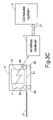
- FIG. 3C is a schematic diagram showing a preferred embodiment of a sheetfed image scanner according to the present invention.
- FIGS. 4A ⁇ 4C are schematic diagrams showing three preferred embodiments of power-transmitting method for providing the wireless carriage module of the flatbed image scanner with power according to the present invention.
- FIGS. 5A and 5B are perspective diagrams showing further preferred embodiments of a flatbed image scanner according to the present invention.
- FIG. 3A is a perspective diagram showing a preferred embodiment of a flatbed image scanner according to the present invention.
- a processing system is implemented with a computer system 2 in this and subsequent embodiments.
- the flatbed image scanner 5 includes a cover (not shown) and a lower casing 51 in which a carriage module 54 , two conductive rods 52 and 53 , and a wireless transmitter 7 is disposed.
- the wireless transmitter 7 is incorporated into the carriage module 54
- a wireless receiver 3 corresponding to the wireless transmitter 7 is separate from the carriage module 54 .
- the two conductive rods 52 and 53 made of metal extend in parallel along the moving direction of the carriage module 54 and penetrate through the carriage module 54 to be in electric contract with the inner circuits (not shown) of the carriage module 54 .
- the carriage module 54 also slidably engages with and moves along the conductive rods 52 and 53 .
- the two conductive rods 52 and 53 electrically connected to a power source (not shown) have therebetween voltage difference to provide electricity for both the carriage module 54 and the wireless transmitter 7 incorporated into the carriage module 54 .
- the carriage module 54 slides along the conductive rods 52 and 53 and picks up image data of the document or picture placed on the transparent scanning platform.
- the image data is then converted into digital data by the carriage module 54 .
- the wireless transmitter 7 After the wireless transmitter 7 receives the digital data, it modulates the digital data into wireless signals and transmits the wireless signals out.
- the wireless receiver 3 located outside the casing 51 receives the wireless signals and demodulating them into the digital data to be outputted to the computer system 2 via a cable 21 such as a universal serial bus (USB) cable or an IEEE 1394 bus cable for further processing.
- a cable 21 such as a universal serial bus (USB) cable or an IEEE 1394 bus cable for further processing.
- USB universal serial bus
- the wireless transmitter 7 and the wireless receiver 3 should comply with the same wireless access protocol such as Bluetooth, IEEE 802.11b, IrDA, or any other known wireless transmission standard.
- the conventional flat flexible cable connecting the carriage module to the circuit board is no longer required so the abrasion problem due to the contact between the flat flexible cable and the transparent scanning platform is overcome.
- the image scanner can be placed according to the user's demand without the restriction of the length of the cable connecting the conventional image scanner and the computer system.
- FIG. 3B is a perspective diagram showing another preferred embodiment of a flatbed image scanner according to the present invention.
- the flatbed image scanner 6 includes a cover (not shown) and a lower casing 61 in which a carriage module 64 , a power supply including a battery device 63 and a charging device 62 , and a wireless transmitter 7 is disposed.
- the wireless transmitter 7 is incorporated into the carriage module 64 , and a wireless receiver 3 corresponding to the wireless transmitter 7 separate from the carriage module 64 is located outside the casing 61 of the flatbed image scanner 6 .
- the battery device 63 is coupled to and moving with the carriage module 64 , and the charging device 62 is fixed on an inner wall of the casing 61 .
- Both the battery device 63 and the charging device 62 have two exposed contacts 63 a , 63 b , 62 a , 62 b , respectively.
- the exposed contacts 63 a and 63 b of the battery device 63 are in electric contact with the exposed contacts 62 a and 62 b of the charging device 62 .
- the charging device 62 charges the battery device 63 so that the battery device 63 can receive enough electricity for the carriage module 64 and the wireless transmitter 7 to proceed to the following scanning operation.
- the carriage module 64 moves and picks up image data of the document or picture to be scanned. The image data is then converted into digital data by the carriage module 64 .
- the wireless transmitter 7 After the wireless transmitter 7 receives the digital data, it modulates the digital data into wireless signals and transmits the wireless signals out.
- the wireless receiver 3 located outside the casing 61 receives the wireless signals and demodulating them into the digital data to be outputted to the computer system 2 via a cable 21 for further processing.
- the wireless transmission is applied to a sheetfed image scanner 4 .
- FIG. 3C is a schematic diagram showing a preferred embodiment of a sheetfed image scanner according to the present invention.
- the wireless transmitter 7 is incorporated into the carriage module 41 and the corresponding wireless receiver 3 is separate from the carriage module 41 . While scanning, the document or picture 8 to be scanned is fed into the sheetfed image scanner 4 and transported by the rollers 80 to pass the scanning passage 81 .
- the fixed carriage module 41 picks up image data of the moving document 8 and converts the image data into digital data.
- the wireless transmitter 7 receives the digital data, it modulates the digital data into wireless signals and transmits the wireless signals out.
- the wireless receiver 3 receives the wireless signals and demodulating them into the digital data to be outputted to the computer system 2 via a cable 21 for further processing.
- FIGS. 4A ?? 4C are schematic diagrams showing three preferred embodiments of power-transmitting method for providing the wireless carriage module of the flatbed image scanner with power according to the present invention.
- the size of the carriage module 54 is enlarged to explain the structure of the power-transmitting medium and does not agree with the exact proportion.
- the power-transmitting medium includes two conductive rods 52 and 53 penetrating the carriage module 54 as described in the preceding paragraph with reference to FIG. 3A .
- the power-transmitting medium includes a conductive rod 52 and a conductive plate 52 a extending along the moving direction of the carriage module 54 .
- the conductive rod 52 and the conductive plate 52 a are arranged at opposite sides of the carriage module 54 .
- the flatbed image scanner 5 When the flatbed image scanner 5 is powered on, there is voltage difference between the conductive rod 52 and the conductive plate 52 a so as to provide electricity for the carriage module 54 and the wireless transmitter 7 .
- An elastic conductor piece 55 may be provided to interface between the conductive plate 52 a and the carriage module 54 for stabilizing the movement of the carriage module 54 and avoiding abrasion of the conductive plate 53 a due to the movement of the carriage module 54 along the conductive rod 52 .
- the power-transmitting medium includes two conductive plates 52 a and 53 a fixed to the casing and extending along the moving direction of the carriage module 54 as shown in FIG. 4C .
- the two conductive plates 52 a and 53 a have therebetween voltage difference when the flatbed image scanner 5 is powered on so as to provide electricity for the carriage module 54 .
- There is no electricity passing through the rod 521 and the rod 521 only serves as a tracking rail of the carriage module 54 .
- Two elastic conductor pieces 55 may be provided to interface between the carriage module 54 and the two conductive plates 52 a and 53 a , respectively, for stabilizing the movement of the carriage module 54 and avoiding abrasion between the carriage module 54 and the conductive plates 52 a and 53 a .
- the conductive plates 52 a and 53 a may be arranged at the inner bottom of the casing, the same inner side wall of the casing, or opposite inner side walls of the casing according to the designer's options and considerations.
- the elastic conductor pieces 55 can be implemented with resilient pieces or wires.
- FIGS. 5A and 5B are perspective diagrams showing further preferred embodiments of a flatbed image scanner according to the present invention.
- the wireless receiver 3 is respectively disposed in the casings 51 and 61 of the flatbed image scanners 5 and 6 .
- the wireless receiver 3 is in communication with the computer 2 via a cable 21 .
- No flat flexible cable is required in the flatbed image scanner containing therein the wireless transmitter 7 and the wireless receiver 3 .
- the wireless transmitter 7 and the wireless receiver 3 can be implemented with two wireless transceivers.
- the transmission is performed by the way that the first wireless transceiver substituted for the wireless transmitter 7 will convert the digital data from the carriage module into wireless signals (modulated digital data) and transmits them out, and than the second wireless transceiver substituted for the wireless receiver 3 receives the wireless signals (modulated digital data) and converted them into the digital data for further processing by the computer system 2 .
- an additional transmission is performed in the following steps.
- the computer system 2 outputs a control signal to the second wireless transceiver.
- the second wireless transceiver converts the control signal into a wireless signal (modulated control signal) and transmits it out.
- the first wireless transceiver receives and demodulates the wireless signal (modulated control signal) into the control signal for controlling the scanning operation of the carriage module.
- the bidirectional transmission implemented by adopting wireless transceivers makes the image scanner more powerful.
- the image scanner including a wireless carriage module according to the present invention can eliminate the physical connection to the carriage module via the flat flexible cable. Therefore, the structure is helpful to miniaturize the image scanner to cater for the current trend.
Abstract
Description
Claims (16)
Applications Claiming Priority (3)
| Application Number | Priority Date | Filing Date | Title |
|---|---|---|---|
| TW093119912A TWI240555B (en) | 2004-07-01 | 2004-07-01 | Image scanner |
| TW093119912 | 2004-07-01 | ||
| TW93119912A | 2004-07-01 |
Publications (2)
| Publication Number | Publication Date |
|---|---|
| US20060001916A1 US20060001916A1 (en) | 2006-01-05 |
| US7724401B2 true US7724401B2 (en) | 2010-05-25 |
Family
ID=35513545
Family Applications (1)
| Application Number | Title | Priority Date | Filing Date |
|---|---|---|---|
| US11/124,976 Active 2029-02-23 US7724401B2 (en) | 2004-07-01 | 2005-05-09 | Image scanner having wireless carriage module |
Country Status (2)
| Country | Link |
|---|---|
| US (1) | US7724401B2 (en) |
| TW (1) | TWI240555B (en) |
Cited By (3)
| Publication number | Priority date | Publication date | Assignee | Title |
|---|---|---|---|---|
| US20080055464A1 (en) * | 2006-08-31 | 2008-03-06 | Samsung Electronics Co., Ltd. | Method of automatically selecting resolution and video receiving apparatus to use the same |
| US20170195501A1 (en) * | 2015-12-30 | 2017-07-06 | Kodak Alaris Inc | Mobile autonomous scalable scanner system |
| US20170195502A1 (en) * | 2015-12-30 | 2017-07-06 | Kodak Alaris Inc. | Mobile autonomous scalable scanner system |
Families Citing this family (7)
| Publication number | Priority date | Publication date | Assignee | Title |
|---|---|---|---|---|
| TW200626813A (en) * | 2005-01-20 | 2006-08-01 | Benq Corp | Gear trains module and electronic device utilizing the same |
| JP4337855B2 (en) * | 2006-09-20 | 2009-09-30 | ブラザー工業株式会社 | Scanning device |
| US20100056049A1 (en) * | 2008-09-04 | 2010-03-04 | Darwin Hu | Wireless Mobile Telescanners |
| TWI469601B (en) * | 2012-11-23 | 2015-01-11 | Primax Electronics Ltd | Duplex scanning device |
| JP6474779B2 (en) * | 2013-03-15 | 2019-02-27 | ワイルドキャット・ディスカバリー・テクノロジーズ・インコーポレイテッドWildcat Discovery Technologies, Inc. | High energy materials for batteries, methods for their production and their use |
| CN104700592A (en) * | 2013-12-06 | 2015-06-10 | 上海诺司纬光电仪器有限公司 | Swinger control system |
| JP6498930B2 (en) * | 2014-12-25 | 2019-04-10 | キヤノンファインテックニスカ株式会社 | Transmission cable fixing mechanism and image reading apparatus having the same |
Citations (7)
| Publication number | Priority date | Publication date | Assignee | Title |
|---|---|---|---|---|
| US4343223A (en) * | 1980-05-23 | 1982-08-10 | The United States Of America As Represented By The United States Department Of Energy | Multiple stage railgun |
| US5172243A (en) * | 1988-09-13 | 1992-12-15 | Sharp Kabushiki Kaisha | Data transmitter-receiver apparatus for transmitting and receiving image data |
| US6040572A (en) * | 1998-05-21 | 2000-03-21 | Hewlett-Packard Company | Notebook styled scanner |
| US6344906B1 (en) * | 1997-09-16 | 2002-02-05 | Cyberscan Technology, Inc. | Universal document scanner controller |
| US20020196478A1 (en) | 2001-06-21 | 2002-12-26 | Struble Christian L. | System and method for wirelessly initiated document scanning and transmission |
| US20040227979A1 (en) * | 2003-05-14 | 2004-11-18 | Yen-Cheng Chen | Image access device with a wireless transmission function |
| US20040262397A1 (en) * | 2003-04-07 | 2004-12-30 | Modest Khovaylo | Optical scanner assembly |
-
2004
- 2004-07-01 TW TW093119912A patent/TWI240555B/en active
-
2005
- 2005-05-09 US US11/124,976 patent/US7724401B2/en active Active
Patent Citations (7)
| Publication number | Priority date | Publication date | Assignee | Title |
|---|---|---|---|---|
| US4343223A (en) * | 1980-05-23 | 1982-08-10 | The United States Of America As Represented By The United States Department Of Energy | Multiple stage railgun |
| US5172243A (en) * | 1988-09-13 | 1992-12-15 | Sharp Kabushiki Kaisha | Data transmitter-receiver apparatus for transmitting and receiving image data |
| US6344906B1 (en) * | 1997-09-16 | 2002-02-05 | Cyberscan Technology, Inc. | Universal document scanner controller |
| US6040572A (en) * | 1998-05-21 | 2000-03-21 | Hewlett-Packard Company | Notebook styled scanner |
| US20020196478A1 (en) | 2001-06-21 | 2002-12-26 | Struble Christian L. | System and method for wirelessly initiated document scanning and transmission |
| US20040262397A1 (en) * | 2003-04-07 | 2004-12-30 | Modest Khovaylo | Optical scanner assembly |
| US20040227979A1 (en) * | 2003-05-14 | 2004-11-18 | Yen-Cheng Chen | Image access device with a wireless transmission function |
Cited By (5)
| Publication number | Priority date | Publication date | Assignee | Title |
|---|---|---|---|---|
| US20080055464A1 (en) * | 2006-08-31 | 2008-03-06 | Samsung Electronics Co., Ltd. | Method of automatically selecting resolution and video receiving apparatus to use the same |
| US20170195501A1 (en) * | 2015-12-30 | 2017-07-06 | Kodak Alaris Inc | Mobile autonomous scalable scanner system |
| US20170195502A1 (en) * | 2015-12-30 | 2017-07-06 | Kodak Alaris Inc. | Mobile autonomous scalable scanner system |
| US9906664B2 (en) * | 2015-12-30 | 2018-02-27 | Kodak Alaris Inc. | Mobile autonomous scalable scanner system |
| US9936089B2 (en) * | 2015-12-30 | 2018-04-03 | Kodak Alaris Inc. | Mobile autonomous scalable scanner system |
Also Published As
| Publication number | Publication date |
|---|---|
| TWI240555B (en) | 2005-09-21 |
| TW200603607A (en) | 2006-01-16 |
| US20060001916A1 (en) | 2006-01-05 |
Similar Documents
| Publication | Publication Date | Title |
|---|---|---|
| US7724401B2 (en) | Image scanner having wireless carriage module | |
| US7388154B2 (en) | Anti-abrasive mechanism confining flat flexible cable in position in flatbed image scanner | |
| US5734328A (en) | Apparatus for switching communication method based on detected communication distance | |
| US6002508A (en) | Optical scanner | |
| CN102572246B (en) | Image pickup apparatus equipped with handle unit | |
| US6975436B2 (en) | Image reading apparatus | |
| US7561298B2 (en) | Image scanner having multiple scanning windows | |
| CN108495015B (en) | Shooting device and electronic equipment | |
| JP2003110821A (en) | Image reader | |
| US20070146821A1 (en) | Image reading apparatus and method thereof | |
| JP2012083515A (en) | Image scanner and multifunctional machine | |
| JP3880966B2 (en) | Anti-friction flat flexible cable | |
| CN112019693B (en) | Image reading apparatus and image forming apparatus | |
| JP2019053109A (en) | Image reading apparatus and image forming apparatus | |
| JP5691378B2 (en) | Image reading device, multifunction device | |
| CN102547046A (en) | Image scanning apparatus and circuit board in image scanning apparatus | |
| JP5230369B2 (en) | Document reader | |
| US7786625B2 (en) | Bus structure | |
| US7817312B2 (en) | Image acquiring device having an optical signal transmission medium | |
| JP4739881B2 (en) | Image reading device | |
| JP6399225B2 (en) | Flexible flat cable and image forming apparatus | |
| CN1306786C (en) | Image scanner | |
| JP3522124B2 (en) | Image data acquisition device | |
| JP2018061085A (en) | Image reading device | |
| CN114679526A (en) | Camera signal transmission device and electronic equipment |
Legal Events
| Date | Code | Title | Description |
|---|---|---|---|
| AS | Assignment |
Owner name: PRIMAX ELECTRONICS LTD.,TAIWAN Free format text: ASSIGNMENT OF ASSIGNORS INTEREST;ASSIGNORS:SHENG, KUNG-CHO;LIN, HUNG-TSE;CHEN, HSI-YU;REEL/FRAME:016553/0160 Effective date: 20050505 Owner name: PRIMAX ELECTRONICS LTD., TAIWAN Free format text: ASSIGNMENT OF ASSIGNORS INTEREST;ASSIGNORS:SHENG, KUNG-CHO;LIN, HUNG-TSE;CHEN, HSI-YU;REEL/FRAME:016553/0160 Effective date: 20050505 |
|
| AS | Assignment |
Owner name: TRANSPACIFIC PLASMA, LLC,TAIWAN Free format text: ASSIGNMENT OF ASSIGNORS INTEREST;ASSIGNOR:PRIMAX ELECTRONICS LTD.;REEL/FRAME:018047/0778 Effective date: 20060626 Owner name: TRANSPACIFIC PLASMA, LLC, TAIWAN Free format text: ASSIGNMENT OF ASSIGNORS INTEREST;ASSIGNOR:PRIMAX ELECTRONICS LTD.;REEL/FRAME:018047/0778 Effective date: 20060626 |
|
| AS | Assignment |
Owner name: PRIMAX ELECTRONICS LTD.,TAIWAN Free format text: LICENSE;ASSIGNORS:TRANSPACIFIC IP LTD.;TRANSPACIFIC PLASMA LLC;REEL/FRAME:018787/0358 Effective date: 20060404 Owner name: PRIMAX ELECTRONICS LTD., TAIWAN Free format text: LICENSE;ASSIGNORS:TRANSPACIFIC IP LTD.;TRANSPACIFIC PLASMA LLC;REEL/FRAME:018787/0358 Effective date: 20060404 |
|
| STCF | Information on status: patent grant |
Free format text: PATENTED CASE |
|
| FEPP | Fee payment procedure |
Free format text: PAYOR NUMBER ASSIGNED (ORIGINAL EVENT CODE: ASPN); ENTITY STATUS OF PATENT OWNER: LARGE ENTITY Free format text: PAYER NUMBER DE-ASSIGNED (ORIGINAL EVENT CODE: RMPN); ENTITY STATUS OF PATENT OWNER: LARGE ENTITY |
|
| AS | Assignment |
Owner name: GIZMODO LIMITED LIABILITY COMPANY, DELAWARE Free format text: MERGER;ASSIGNOR:TRANSPACIFIC PLASMA, LLC;REEL/FRAME:030628/0659 Effective date: 20130213 |
|
| AS | Assignment |
Owner name: INTELLECTUAL VENTURES I LLC, DELAWARE Free format text: MERGER;ASSIGNOR:GIZMODO LIMITED LIABILITY COMPANY;REEL/FRAME:030639/0298 Effective date: 20130214 |
|
| FPAY | Fee payment |
Year of fee payment: 4 |
|
| MAFP | Maintenance fee payment |
Free format text: PAYMENT OF MAINTENANCE FEE, 8TH YEAR, LARGE ENTITY (ORIGINAL EVENT CODE: M1552) Year of fee payment: 8 |
|
| MAFP | Maintenance fee payment |
Free format text: PAYMENT OF MAINTENANCE FEE, 12TH YEAR, LARGE ENTITY (ORIGINAL EVENT CODE: M1553); ENTITY STATUS OF PATENT OWNER: LARGE ENTITY Year of fee payment: 12 |