US7724435B1 - Importance sampling techniques based on adjustable differential group delay (DGD) elements - Google Patents
Importance sampling techniques based on adjustable differential group delay (DGD) elements Download PDFInfo
- Publication number
- US7724435B1 US7724435B1 US11/758,614 US75861407A US7724435B1 US 7724435 B1 US7724435 B1 US 7724435B1 US 75861407 A US75861407 A US 75861407A US 7724435 B1 US7724435 B1 US 7724435B1
- Authority
- US
- United States
- Prior art keywords
- dgd
- sections
- polarization
- pmd
- variable
- Prior art date
- Legal status (The legal status is an assumption and is not a legal conclusion. Google has not performed a legal analysis and makes no representation as to the accuracy of the status listed.)
- Expired - Lifetime
Links
Images


Classifications
-
- G—PHYSICS
- G02—OPTICS
- G02B—OPTICAL ELEMENTS, SYSTEMS OR APPARATUS
- G02B6/00—Light guides; Structural details of arrangements comprising light guides and other optical elements, e.g. couplings
- G02B6/24—Coupling light guides
- G02B6/26—Optical coupling means
- G02B6/28—Optical coupling means having data bus means, i.e. plural waveguides interconnected and providing an inherently bidirectional system by mixing and splitting signals
- G02B6/293—Optical coupling means having data bus means, i.e. plural waveguides interconnected and providing an inherently bidirectional system by mixing and splitting signals with wavelength selective means
- G02B6/29379—Optical coupling means having data bus means, i.e. plural waveguides interconnected and providing an inherently bidirectional system by mixing and splitting signals with wavelength selective means characterised by the function or use of the complete device
- G02B6/29395—Optical coupling means having data bus means, i.e. plural waveguides interconnected and providing an inherently bidirectional system by mixing and splitting signals with wavelength selective means characterised by the function or use of the complete device configurable, e.g. tunable or reconfigurable
-
- G—PHYSICS
- G02—OPTICS
- G02B—OPTICAL ELEMENTS, SYSTEMS OR APPARATUS
- G02B6/00—Light guides; Structural details of arrangements comprising light guides and other optical elements, e.g. couplings
- G02B6/24—Coupling light guides
- G02B6/26—Optical coupling means
- G02B6/27—Optical coupling means with polarisation selective and adjusting means
- G02B6/2706—Optical coupling means with polarisation selective and adjusting means as bulk elements, i.e. free space arrangements external to a light guide, e.g. polarising beam splitters
- G02B6/2713—Optical coupling means with polarisation selective and adjusting means as bulk elements, i.e. free space arrangements external to a light guide, e.g. polarising beam splitters cascade of polarisation selective or adjusting operations
-
- G—PHYSICS
- G02—OPTICS
- G02B—OPTICAL ELEMENTS, SYSTEMS OR APPARATUS
- G02B6/00—Light guides; Structural details of arrangements comprising light guides and other optical elements, e.g. couplings
- G02B6/24—Coupling light guides
- G02B6/26—Optical coupling means
- G02B6/27—Optical coupling means with polarisation selective and adjusting means
- G02B6/2753—Optical coupling means with polarisation selective and adjusting means characterised by their function or use, i.e. of the complete device
- G02B6/278—Controlling polarisation mode dispersion [PMD], e.g. PMD compensation or emulation
-
- G—PHYSICS
- G02—OPTICS
- G02B—OPTICAL ELEMENTS, SYSTEMS OR APPARATUS
- G02B6/00—Light guides; Structural details of arrangements comprising light guides and other optical elements, e.g. couplings
- G02B6/24—Coupling light guides
- G02B6/26—Optical coupling means
- G02B6/27—Optical coupling means with polarisation selective and adjusting means
- G02B6/2726—Optical coupling means with polarisation selective and adjusting means in or on light guides, e.g. polarisation means assembled in a light guide
- G02B6/274—Optical coupling means with polarisation selective and adjusting means in or on light guides, e.g. polarisation means assembled in a light guide based on light guide birefringence, e.g. due to coupling between light guides
Definitions
- This application relates to optical polarization of light and polarization-mode dispersion in optical media, and more specifically, to techniques and systems for emulating and compensating polarization-mode dispersion in optical media such as optical fibers.
- Various optical media are birefringent by exhibiting different refractive indices for different polarizations of light.
- Fibers for example, may be birefringent and the axis of birefringence of a fiber may change with time, often randomly with the fluctuations in the operating conditions such as stresses or temperatures.
- the polarization of an optical signal which may be represented by two polarization components along two orthogonal principal polarization states, can vary and thus be significantly distorted after propagation. This effect is called polarization-mode dispersion (“PMD”) and the first-order of PMD may be characterized by the average differential group delay (“DGD”) between the two principal states of polarization.
- PMD polarization-mode dispersion
- DTD average differential group delay
- PMD effects are undesirable in various applications including optical fiber communication systems.
- One way of characterizing PMD effects is to use a PMD emulator to emulate actual PMD in a system of interest, such as a fiber system.
- a PMD emulator may be used to test a PMD compensator prior to actual deployment of the compensator.
- One implementation of a device of this application includes birefringent sections cascaded in series to form an optical path and configured to produce their respective differential group delays, tunable polarization devices each coupled between two adjacent birefringent sections to rotate polarization of light transmitting therethrough. At least one tunable polarization device coupled between a first birefringent section and a second birefringent section is controlled in responsive to a switch control signal to switch polarization of light between a first state and a second state.
- a first principal polarization of the light along a slow principal axis and a second principal polarization of the light along a fast principal axis of the first birefringent section are aligned with slow and fast principal axes of the second birefringent section, respectively.
- a first principal polarization of the light along a slow principal axis and a second principal polarization of the light along a fast principal axis of the first birefringent section are aligned with fast and slow principal axes of the second birefringent section, respectively.
- a control unit is coupled to control operations of the tunable polarization devices to produce a polarization-mode dispersion profile in light transmitting through the optical path.
- a device uses variable DGD sections cascaded in series to form an optical path.
- Each variable DGD section is operable to produce a variable differential group delay and is configured to include cascaded birefringent segments of different lengths, and tunable polarization elements each coupled between two adjacent birefringent segments to control polarization of light.
- Polarization controllers are coupled in the optical path where each polarization controller is coupled between two adjacent variable DGD sections to control polarization of light transmitting therethrough.
- the device under this implementation further includes a control unit coupled to control the variable DGD sections and the polarization controllers to produce a polarization-mode dispersion profile in light transmitting through the optical path.
- the devices of this application may be used in various application, including but not limited to, emulating PMD in real fibers, compensation for PMD in optical signals, and performing importance sampling in PMD emulations.
- FIG. 1 shows one implementation of a PMD emulator with fixed birefringent sections cascaded to form an optical path.
- FIG. 2 illustrates exemplary modes of operation of a magneto-optic polarization rotators for polarization rotation and polarization switching.
- FIGS. 3A , 3 B, 4 A, 4 B, 5 A, and 5 B show simulated PMD results for the emulator in FIG. 1 .
- FIGS. 6 , 7 , and 8 show exemplary PMD compensating systems.
- FIG. 9 shows another implementation of a PMD emulator.
- FIGS. 10 and 11 illustrate measured PMD outputs from the emulator in FIG. 9 .
- FIG. 12 shows a PMD emulator with a feedback control based on the design in FIG. 9 .
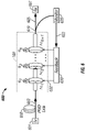
- FIG. 13 illustrates importance sampling using a PMD emulator with three programmable DGD elements separated by two electrically-driven polarization controllers based on the design shown in FIG. 9 , where the importance sampling is accomplished by applying a biased DGD distribution to each section (chosen to emphasize the region of interest) and then appropriately weighting the results to obtain the desired probability density function (pdf).
- a biased DGD distribution to each section (chosen to emphasize the region of interest) and then appropriately weighting the results to obtain the desired probability density function (pdf).
- FIGS. 15A and 15B show the 2nd-order PMD pdf for the importance sampling experiment described in FIGS. 14A and 14B , wherein FIG. 15A shows the measured output pdf and FIG. 15B shows the pdf after renormalizing the data (the 3-section emulator produces a 2nd-order pdf with the correct shape, but a slightly lower average than that of a real fiber because of the small number of sections).
- FIGS. 16A , 16 B, and 16 C show the multiple importance sampling results, wherein FIG. 16A shows the three DGD distributions applied to each section (840 samples/distribution), FIG. 16B shows the resulting DGD distribution showing that each pdf generates samples in different regions to cover the entire Maxwellian, and FIG. 16C shows the resulting 2nd-order PMD pdf (the insets show the pdfs on a linear scale where it is evident that better coverage of lower values is achieved in comparison to the case shown in FIGS. 14A-15B ).
- the PMD emulators and compensators of this application include multiple birefringent sections for transmitting light and tunable optical rotators or polarization controllers coupled between two adjacent birefringent sections.
- each of the birefringent sections has a fixed DGD and at least one optical polarization switch is coupled between two adjacent birefringent sections to switch the relative orientation between the principal axes of the sections at 0 degree to add the DGD values of the sections, and at 90 degrees to subtract the DGD values of the sections.
- the polarization switch and other polarization rotators or controllers are tuned to emulate a desired PMD characteristics.
- each birefringent section is configured to have a tunable DGD value and the a polarization controller is coupled between two adjacent sections. The DGD value of each section and the polarization controllers are tuned to emulate the desired PMD characteristics.
- Such devices can operate to produce tunable, different PMD statistics and tunable, different averaged DGD values for different PMD statistics.
- such devices may be configured to be programmable with high stability and repeatability. Notably, such devices may be used to perform importance sampling in PMD emulations.
- FIG. 1 shows one implementation of an all-order PMD emulator 100 with fixed birefringent sections 110 along an optical path.
- the birefringent sections 110 may be implemented by using a suitable birefringent material, such as birefringent crystals and polarization-maintaining (“PM”) fibers.
- PM polarization-maintaining
- Different birefringent sections 110 are configured to produce fixed and DGD values, ⁇ i .
- Different DGD sections 110 may have different DGD values, or some may have different DGD values while others have the same DGD values, or all DGD sections 110 may have the same DGD values.
- Such DGD values for different sections 110 may be optimized for specific applications.
- the birefringent sections 110 may be arranged in a number of configurations, including their DGD values increase or decrease from the input side to the output side.
- Tunable polarization rotators 120 and at least one optical polarization switch 130 are used to interconnect the fixed birefringent sections 110 .
- Each rotator 120 is operable to rotate the polarization of received light by an adjustable angle.
- the switch 130 operates to switch the polarization of received light between a first state where the slow and fast principal axes of the preceding section are respectively aligned with the slow and fast principal axes of the succeeding section, and a second state where the slow and fast principal axes of the preceding section are respectively aligned with the fast and slow principal axes of the succeeding section.
- the switch 130 is set to the first state, the fixed DGD values of the two connected adjacent sections 110 are added; in the second state, the fixed DGD values of the connected two adjacent sections 110 are subtracted.
- this switching operation changes the total DGD value of the two adjacent sections and thus the averaged DGD value of a particular PMD statistics.
- This controllable switching operation of the switch 130 and the controllable rotating operation of other rotators 120 are combined to tune the generated PMD profile for emulating any desired PMD effects.
- the switch 130 and the rotators 120 may be designed to eliminate all moving parts and to rotate the polarization in response to a control signal.
- magnetooptic (MO) polarization rotators may be used to rotate the polarization in response to an external control voltage applied to the MO element.
- MO magnetooptic
- Such a MO device has no moving parts and hence eliminates various technical shortcomings associated with devices with moving parts, such as durability, repeatability, tear and wear issues.
- the typical relationship between the applied voltage (V) and the rotation angle ( ⁇ ) of MO polarization rotators 120 is shown in FIG. 2 . Within a selected voltage range from V 1 to V 2 , the rotation angle of the MO rotator may be a linear function of the applied voltage V.
- the rotation angle is fixed with either ⁇ 45 or +45 degrees.
- This operating feature of the MO rotators 120 allows for small rotation angles by varying the control voltages with small steps between V 1 and V 2 .
- the same MO device used for the rotators 120 may be controlled to operate as the switch 130 , where the input polarization state can be either switched along the slow or fast axes of the birefringent sections by changing the control voltages either from a value less than V 1 to a value greater than V 2 or vice versa.
- control voltages on the MO rotators 120 may be varied with a given angle step and thus the polarization coupling between different birefringent sections 110 can change accordingly. This operation allows for different PMD profile samples to be obtained. Since the fixed lengths of the birefringent sections 110 are designed according to the PMD statistics, using proper control, the desired PMD distribution can be achieved within a number of samples.
- One or more optical polarization switches 130 are used to tune the average PMD value in the output of the emulator 100 .
- the DGD values of two adjacent sections 110 connected by the switch 130 can either add together or cancel each other.
- the switch 130 in effect operates to combine two adjacent birefringent sections 110 into a single birefringent section with a fixed DGD value at either the sum of the DGD values or the difference of the DGD values.
- the total configuration of the emulator 100 can be changed to a new configuration that has a different effective number of birefringent sections 110 with different DGD values based on how the voltages to the MO devices are controlled.
- an optical rotator 120 in one configuration may be controlled as an optical switch 130 in another configuration and the number of optical switches 130 and the location of each switch 130 may be adjusted to achieve a desired configuration of the rotators 120 and the switches 130 .
- the average DGD value of the emulator 100 may also be changed accordingly.
- rotating of the other rotators with small angles by voltages within the range from V 1 to V 2 can change the PMD statistics to different profiles with the same fixed average PMD value.
- the tested emulator configurations described here are based on the same physical device but with different control configurations on the MO devices. More specifically, a total of 16 pieces of birefringent crystals as the sections 110 are interconnected with 15 MO polarization rotating devices. The lengths of the birefringent crystals are arranged in a binary power series, increasing by a factor of 2 for each section.
- the normalized DGD values of the crystals are 1, 2, 4, 8, 16, and 32.
- the 16 crystals are arranged in the following configuration identified by their normalized DGD values:
- some sections have the same DGD values and other sections have different DGD values.
- some of the MO devices may be controlled to switch the polarization coupling condition between two adjacent sections so that some of the crystals can either add or cancel their DGD values.
- Three different device configurations are described below by using the same 16 crystals to achieve different PMD dispersion profiles with different average PMD values.
- FIGS. 3A and 3B shows simulation results for a 10-ps average PMD with the following configuration for the MO devices:
- FIGS. 4A and 4B show simulation results of a 20-ps average PMD emulator with a different MO device configuration of
- FIGS. 5A and 5B show simulation results of a 30-ps average PMD emulator with the following MO device configuration of
- the corresponding effective 8-section DGD emulator has a section configuration of
- PMD emulators have no moving parts and provides a simple and compact design which can be manufactured at a relatively low cost; it can provide not only first-order DGD emulation but also all-order PMD effects that are more close to the real fiber statistics; the average PMD can be tuned by switching some of the MO rotators with simple electronic controls; any one of the emulated PMD profiles can be repetitively achieved within a given environmental condition; and the average PMD value can be changed.
- the device in FIG. 1 may be used at an optical receiving terminal as a higher-order PMD compensator by using either a feedback or feed-forward control mechanism for controlling the rotators between DGD sections.
- FIG. 6 illustrates a use of the device 100 in FIG. 1 as a PMD compensator in a fiber system 600 based on a feedback control.
- An optical transmitter 601 produces an output signal 603 for transmission in a PMD fiber link 602 .
- the device 100 is coupled before an optical receiver 607 to compensate for the PMD in the received signal 603 to produce a PMD-compensated signal 605 for the receiver 607 .
- An optical splitter 610 such as a fiber coupler, may be used to split a fraction of the output 605 to a polarization detection module 620 which measures the polarization of the light 605 .
- the output 622 of the module 620 is fed into a feedback control 630 for controlling the device 100 to compensate for the PMD in the signal 603 .
- the feedback control 603 in response to the signal 622 , produces a control signal 632 , which may include control signals for the rotators 120 within the device 100 , to control the device 100 so that the PMD produced by the device 100 negates the PMD in the received light 603 .
- the above feedback control is reactive in nature and does not have or does not respond to information on the input polarization received by the device. It controls the polarization rotators 120 in the device 100 based on the output polarization to correct the error in the output polarization. It is recognized that this may cause certain elements in the device to be out of its operating range and thus requires reset an out-of-range element such as a rotator 120 back to its normal operating range. This resetting is slow and reduces the speed of the feedback control.
- FIG. 7 shows a fiber system 700 that implements the device 100 in FIG. 1 as a PMD compensator based on an alternative feed-forward control.
- the feed-forward control includes an input polarization detection module 710 and a feed-forward control circuit 720 .
- the polarization detection module 710 measures the state of the input polarization of the input optical signal 603 .
- This module 710 may be an in-line polarimeter which transmits a received optical signal and measures its polarization at the same time without altering the input polarization.
- the module 710 may be a polarimeter that destroys the polarization upon measuring the polarization.
- Such a polarimeter may be coupled in the system out of the main optical path to receive a fraction of the input signal 603 by using an optical coupler or splitter in the path of the input beam 603 to tap the input signal 603 so that the majority of the input signal 603 continues to propagate to the PMD compensator 100 .
- the module 710 produces an electrical output signal 712 that indicates the state of input polarization of the input 603 .
- the circuit 720 responds to the signal 712 to set the polarization elements in the device 100 so that the PMD produced by the device 100 negates the measured PMD in the input light 603 .
- the feed-forward control circuit 720 may include a look-up table to store all possible settings for the elements in side the device 100 for all possible PMD profiles in the input light 603 . Hence, the circuit 720 does not need to perform complex computation and can quickly respond to the measurement in the signal 712 .
- FIG. 8 further shows a fiber system 800 that uses both feedback and feed-forward controls in combination.
- the presence of both the feed-forward control and the feedback control allows the two controls to complement each other to provide a more efficient PMD compensation.
- the feed-forward control can provide a coarse PMD compensating mechanism for setting the polarization elements in the device 100 . Since the feed-forward control does not know whether the final PMD of the output signal, the feedback control can provides an additional finer PMD compensation based on the measurement on the output light to finely tune the polarization elements in the device 100 to further reduce the PMD.
- FIG. 1 Other applications of the device 100 in FIG. 1 may also be possible, such as investigation of PMD effects on high data rate digital fiber transmission systems, dynamic conditions in optical networks, and RF signal transmission.
- FIG. 9 shows one implementation of a tunable PMD emulator 900 that uses multiple birefringent sections 910 with variable DGD values that can be adjusted in response to control signals 931 . At least three sections 910 are needed to emulate all possible PMD profiles in a real fiber.
- a polarization controller 920 is coupled between two adjacent sections 910 . Different from a polarization rotator which can only rotate the polarization of received light in a plane, the polarization controller 920 can control and manipulate the input polarization to produce an output polarization at any position on the Poincaré sphere, i.e., a 3-dimensional control of the polarization.
- a control unit 930 such as a microprocessor-based control unit, may be used to produce the control signals 931 for the variable sections 910 and the control signals 932 for the polarization controllers 920 .
- This combination of variable DGD values in sections 910 and the polarization controllers 920 provides high-speed, stable, and repeatable PMD emulation with tunable PMD profiles and tunable average PMD values.
- This distribution of the segment lengths can reduce the number of polarization rotators needed.
- Exemplary implementations of such a variable DGD section 910 are described in U.S. Pat. No. 5,978,125 to Yao where the birefringent segments successively increase or decrease their lengths by a factor of 2 between two adjacent segments along the optical path.
- electrically-driven polarization switches may also be used to connect adjacent birefringent segments within each section 910 .
- the sections 910 may be digitally programmed via the control signals 931 to generate any DGD value, e.g., from ⁇ 45 ps to +45 ps with a high tuning speed, e.g., less than 1 ms and a fine resolution of, e.g., 1.40 ps.
- the control unit 930 may be designed to control the emulator 900 to randomly generate any desired DGD distribution.
- the polarization controllers 920 may be implemented by, e.g., fiber-squeezer-based polarization controllers where each polarization controller includes 3 or more fiber squeezers engaged at different locations of a fiber to squeeze the fiber along two different directions. See, e.g., U.S. Pat. No.
- the polarization controllers 920 may be controlled to uniformly scatter the polarization between sections 910 over the Poincaré sphere.
- the DGD values of each section 910 are varied according to a Maxwellian distribution with average, ⁇ . This yields an average DGD of 31 ⁇ 2 ( ⁇ ) for the entire emulator and an average 2nd-order PMD distribution that approximately simulates the PMD of a real fiber.
- the device 900 in FIG. 9 combines the tunable DGD distribution from the variable DGD sections 910 and the tuning of the polarization controllers 920 to achieve accurate, stable, and repeatable PMD statistics.
- the DGD distributions from different variable DGD sections 910 can be adjusted independent from one another. Different sets of settings for the sections 910 and polarization controllers 920 are used to produce a set of outputs to fit a desired PMD statistics.
- the corresponding 2nd-order PMD distributions have averages of 38, 268, and 471 ps 2 , which are approximately 30% lower than expected for a real fiber. All of the PMD measurements were performed using the Jones matrix method of a commercial PMD analyzer. Additional measurements of the sample emulator also show highly stable operation and repeatability with a variation in DGD less than about 5% and a variation in the 2 nd order PMD less than 10% for a period over 30 minutes. Hence, such an emulator may be used to generate a look-up table of control parameters and the corresponding DGD output values. The look-up table may be used to control the subsequent operations of the emulator.
- FIG. 12 shows one implementation of a PMD emulator 1200 with a dynamic feedback control for each polarization rotator 920 .
- a feedback control may be used to reduce or minimize any drift or variation in the output of the emulator caused by various factors including temperature variation, usually large temperature changes (more than a few degrees), and perturbation to the single-mode fiber pigtails between the sections.
- in-line polarimeters 1210 are inserted after each section and a polarization controller 1230 and another in-line polarimeter 1210 are added at the output of the emulator.
- the polarimeters 1210 are used to record the state of polarization (SOP) between sections for different emulator states.
- SOP state of polarization
- the additional SOP information allows for construction of the lookup table of output first and second-order PMD vectors versus the input DGD values and SOP parameters. After recording the input and corresponding output parameters for each randomly-generated sample during a long system test, the operator can return to any previously recorded PMD state (e.g. one that caused high penalty) for further investigation by simply adjusting the DGD sections 910 and polarization controllers 920 to re-acquire the set of input values for that sample.
- the polarization controllers 920 are adjusted by the respective feedback controls 1220 to bring the output PMD to the previously-established PMD in the look-up table.
- this table may be used to re-acquire exactly a desired PMD state using automatic feedback control of the polarization controllers to obtain the needed SOP coupling.
- the PMD emulators shown in FIGS. 9 and 12 may also be used as PMD compensators with the control mechanisms shown in FIGS. 6 , 7 , and 8 .
- the PMD emulators shown in FIGS. 9 and 12 it is now possible to use such emulators to emulate real PMD states based on the importance sampling (SI) technique without requiring deterministic control of the polarization coupling between sections. This feature is described in the following sections.
- SI importance sampling
- the fiber birefringence varies randomly with time and the optical frequency. Such variations cause the PMD of the fiber to be a statistical parameter.
- the instantaneous PMD of a fiber is characterized by a vector, ⁇ , whose direction determines the fiber's two principle states of polarization and whose magnitude is the differential-group-delay (DGD).
- the DGD generally follows a Maxwellian distribution that falls off to low probabilities at about 3 times the average value and extends out to infinity. It is the occasional events in the tail of the distribution that are likely to cause system outages.
- PMD-based system outages penalty >1 dB
- PMD emulators are used to cycle through different PMD states.
- Importance sampling (IS) technique is a powerful tool for obtaining very low probability events with relatively few sample points. This is accomplished by altering the method of obtaining the random samples to concentrate the measured results in the area of interest in the sample space. This can distort the probability distribution of the measured results, so each sample must then be appropriately weighted to map the measured values back onto the proper distribution function.
- Importance sampling techniques for PMD emulation have been accomplished using computer simulations. This is because a critical drawback of previously reported PMD emulators is that they do not possess the programmability, or stability, required to perform IS. These emulators are typically constructed with multiple fixed-DGD elements such as PM fibers or birefringent crystals. Different PMD states are then obtained by randomly varying the polarization coupling between sections. To perform IS with these emulators requires deterministic control of the coupling angle between the PMD vectors of adjacent sections in order to preferentially align them to obtain rare PMD events.
- the use of the PMD emulators of this application allows for experimental importance sampling that bypasses these and other obstacles and can produce improved statistics without the need to determine and control the direction of the PMD vector between sections.
- the PMD emulators of this application shown in FIGS. 9 and 12 are designed with tunable, rather than static, DGD elements. As a result, the importance sampling can be accomplished by biasing the distribution of DGD values applied to each element, as opposed to controlling the coupling angles between sections. As such, only uniform scattering of the polarization coupling between sections is required, which is easily accomplished with electrically driven polarization controllers.
- This technique also overcomes a problem encountered with the previous methods in that, by preferentially aligning the PMD vectors to obtain large DGD values, the possible range of 2nd-order PMD states is severely limited, thereby distorting the 2nd-order statistics.
- Multiple importance sampling techniques can also be used to combine the results from three different distributions to achieve better coverage of the entire sample space. The resulting distribution tail extends to 10 ⁇ 30 .
- the importance sampling may be implemented in connection with a microprocessor that is integrated to or coupled to the control unit 930 .
- the microprocessor is programmed to carry out the operations for the importance sampling. Some of these operations are described in the following examples.
- the emulator 900 in FIG. 9 is controlled so that the variable DGD sections 910 can be digitally programmed to generate any of 32 DGD values between 0.7 to 45.65 ps in 1.4-ps steps, with a tuning speed of ⁇ 1 ms.
- the DGD values applied to each section are Maxwellian distributed with an average of ⁇ >/(31 ⁇ 2).
- the polarization controllers are randomly varied to uniformly scatter the polarization state over the Poincaré sphere between sections.
- FIG. 13 illustrates the importance sampling technique.
- the programmability of the variable DGD sections are used to perform IS by applying randomly selected DGD values from a probability density function (pdf) other than a Maxwellian. Any pdf may be used, but the best choices are those that will tend to generate more output samples in the region of interest with the fewest possible measurements. In performed measurements, a uniform distribution of DGD values to each element is applied over their full 45 ps range.
- PDF probability density function
- the DGD applied to each DGD section and the corresponding output DGD and 2nd-order PMD are recorded for each sample.
- the measured output values do not follow the desired Maxwellian distribution and should be properly weighted to adjust their probabilities to match the desired Maxwellian statistics.
- p*(xi) be the probability using the uniform pdf.
- three likelihood ratios, p(xi)/p*(xi) are computed using the three applied DGD values for the xi's.
- the three ratios are then multiplied together and divided by the total number of samples to determine the “weight” for each sample.
- the output DGD values are then sorted, while keeping track of the corresponding weights.
- the DGDs and corresponding weights are grouped into DGD bins and the weights in each bin are summed to obtain the probability for that bin. These probabilities are then plotted alongside a Maxwellian, integrated over each bin, for comparison. Throughout the experiment, all PMD measurements were performed using the Jones Matrix method of a commercial PMD analyzer.
- FIGS. 14A , 14 B, 15 A and 15 B show the distributions of the unprocessed, measured values.
- FIGS. 14B and 15B show the measured samples.
- a technique of “multiple importance sampling” is also used to combine the results of several experiments using different DGD pdfs applied to each section.
- FIG. 16A an unbiased, Maxwellian pdf was used to obtain several values in the low-DGD region, a negatively sloped linear pdf was used to obtain low to medium DGDs and a positively sloped pdf was used to obtain high DGDs.
- 840 samples were taken for each distribution. The experimental results are weighted to obtain the distributions shown in FIGS. 16B and 16C .
- the multiple IS technique provides better coverage of the entire sample space.
- the resulting distribution tail extends to 10 ⁇ 30 .
Abstract
Description
Claims (5)
Priority Applications (1)
| Application Number | Priority Date | Filing Date | Title |
|---|---|---|---|
| US11/758,614 US7724435B1 (en) | 2002-01-22 | 2007-06-05 | Importance sampling techniques based on adjustable differential group delay (DGD) elements |
Applications Claiming Priority (5)
| Application Number | Priority Date | Filing Date | Title |
|---|---|---|---|
| US35108502P | 2002-01-22 | 2002-01-22 | |
| US43922803P | 2003-01-10 | 2003-01-10 | |
| US35028303A | 2003-01-22 | 2003-01-22 | |
| US11/075,643 US7227686B1 (en) | 2002-01-22 | 2005-03-08 | Tunable PMD emulators and compensators |
| US11/758,614 US7724435B1 (en) | 2002-01-22 | 2007-06-05 | Importance sampling techniques based on adjustable differential group delay (DGD) elements |
Related Parent Applications (1)
| Application Number | Title | Priority Date | Filing Date |
|---|---|---|---|
| US11/075,643 Continuation US7227686B1 (en) | 2002-01-22 | 2005-03-08 | Tunable PMD emulators and compensators |
Publications (1)
| Publication Number | Publication Date |
|---|---|
| US7724435B1 true US7724435B1 (en) | 2010-05-25 |
Family
ID=38090190
Family Applications (2)
| Application Number | Title | Priority Date | Filing Date |
|---|---|---|---|
| US11/075,643 Expired - Lifetime US7227686B1 (en) | 2002-01-22 | 2005-03-08 | Tunable PMD emulators and compensators |
| US11/758,614 Expired - Lifetime US7724435B1 (en) | 2002-01-22 | 2007-06-05 | Importance sampling techniques based on adjustable differential group delay (DGD) elements |
Family Applications Before (1)
| Application Number | Title | Priority Date | Filing Date |
|---|---|---|---|
| US11/075,643 Expired - Lifetime US7227686B1 (en) | 2002-01-22 | 2005-03-08 | Tunable PMD emulators and compensators |
Country Status (1)
| Country | Link |
|---|---|
| US (2) | US7227686B1 (en) |
Cited By (5)
| Publication number | Priority date | Publication date | Assignee | Title |
|---|---|---|---|---|
| US20100021178A1 (en) * | 2008-07-22 | 2010-01-28 | National Institute Of Information And Communications Technology | Polarization direction synchronization detecting circuit and receiving apparatus |
| US20100239245A1 (en) * | 2009-03-21 | 2010-09-23 | General Photonics Corporation | Polarization Mode Emulators and Polarization Mode Dispersion Compensators Based on Optical Polarization Rotators with Discrete Polarization States |
| US20130229700A1 (en) * | 2012-03-05 | 2013-09-05 | Oki Electric Industry Co., Ltd. | Polarization mode dispersion generating device, method for generating polarization mode dispersion and polarization mode dispersion compensating device |
| US8780433B2 (en) | 2011-09-28 | 2014-07-15 | General Photonics Corporation | Polarization scrambling based on cascaded optical polarization devices having modulated optical retardation |
| US8787755B1 (en) | 2008-02-04 | 2014-07-22 | General Photonics Corporation | Monitoring polarization-mode dispersion and signal-to-noise ratio in optical signals based on polarization analysis |
Families Citing this family (15)
| Publication number | Priority date | Publication date | Assignee | Title |
|---|---|---|---|---|
| US7227686B1 (en) | 2002-01-22 | 2007-06-05 | General Photonics Corporation | Tunable PMD emulators and compensators |
| US7154659B1 (en) * | 2002-04-18 | 2006-12-26 | General Photonics Corporation | Optical depolarizers and DGD generators based on optical delay |
| US7391977B2 (en) | 2003-03-12 | 2008-06-24 | General Photonics Corporation | Monitoring mechanisms for optical systems |
| US7796894B1 (en) | 2003-07-30 | 2010-09-14 | General Photonics Corporation | Reduction of noise and polarization mode dispersion (PMD) based on optical polarization stabilizer in fiber transmission |
| US7522785B2 (en) * | 2004-12-01 | 2009-04-21 | General Photonics Corporation | Measurements of polarization-dependent loss (PDL) and degree of polarization (DOP) using optical polarization controllers |
| US7693419B1 (en) | 2005-11-23 | 2010-04-06 | General Photonics Corporation | Optical spectrum analysis using optical interferometry |
| US7546039B1 (en) * | 2005-11-28 | 2009-06-09 | At&T Intellectual Property, Ii, L.P. | Systems, devices, and methods for controlling outage probabilities |
| US8073326B2 (en) * | 2006-12-06 | 2011-12-06 | General Photonics Corporation | Optical polarization division multiplexing in optical communication |
| US7723670B1 (en) | 2007-03-26 | 2010-05-25 | General Photonics Corporation | Optical differential group delay module with folded optical path |
| US7952711B1 (en) | 2007-03-26 | 2011-05-31 | General Photonics Corporation | Waveplate analyzer based on multiple tunable optical polarization rotators |
| US7945130B2 (en) * | 2007-11-15 | 2011-05-17 | General Photonics Corporation | Mode scrambling apparatus for multimode fiber |
| US8345238B2 (en) * | 2008-02-04 | 2013-01-01 | General Photonics Corporation | Measuring optical spectral property of light based on polarization analysis |
| CN102200600A (en) * | 2010-03-22 | 2011-09-28 | 北京高光科技有限公司 | Polarization mode dispersion emulators and polarization mode dispersion compensators based on three solid state polarization rotators |
| WO2013164655A1 (en) * | 2012-05-04 | 2013-11-07 | Universidad De Málaga | Highly tolerant and tuneable integrated optical polarization rotator |
| JP6303691B2 (en) * | 2014-03-26 | 2018-04-04 | 富士通株式会社 | Polarization state detection apparatus and method, and optical communication system, optical transmitter and optical receiver |
Citations (103)
| Publication number | Priority date | Publication date | Assignee | Title |
|---|---|---|---|---|
| US3302028A (en) | 1963-06-10 | 1967-01-31 | Rca Corp | High efficiency light modulation system |
| US3684350A (en) | 1970-08-17 | 1972-08-15 | Westinghouse Electric Corp | Light beam polarization modulator |
| US3719414A (en) | 1970-08-28 | 1973-03-06 | Westinghouse Electric Corp | Polarization independent light modulation means using birefringent crystals |
| US4389090A (en) | 1980-09-04 | 1983-06-21 | The Board Of Trustees Of Leland Stanford Jr. Univ. | Fiber optic polarization controller |
| US4461543A (en) | 1982-03-26 | 1984-07-24 | Sperry Corporation | Electro optic switch |
| US4798436A (en) | 1985-07-30 | 1989-01-17 | British Telecommunications, Plc | Optical fused couplers |
| US5004312A (en) | 1989-03-10 | 1991-04-02 | Nec Corporation | Method for controlling a polarization of light |
| US5111322A (en) | 1991-04-04 | 1992-05-05 | At&T Bell Laboratories | Polarization multiplexing device with solitons and method using same |
| US5153676A (en) | 1983-04-26 | 1992-10-06 | The Board Of Trustees Of The Leland Stanford Junior University | Apparatus and method for reducing phase errors in an interferometer |
| US5251057A (en) | 1989-10-13 | 1993-10-05 | Xerox Corporation | Multiple beam optical modulation system |
| US5317445A (en) | 1992-12-16 | 1994-05-31 | General Electric Company | Optical device with spatial light modulators for switching polarized light |
| US5373393A (en) | 1993-06-01 | 1994-12-13 | General Electric Company | Opical interferometric device with spatial light modulators for switching substantially coherent light |
| US5381250A (en) | 1992-11-06 | 1995-01-10 | Displaytech, Inc. | Electro-optical switch with 4 port modules with electro-optic polarization rotators |
| US5473457A (en) | 1993-12-20 | 1995-12-05 | Nec Corporation | Method and apparatus for compensating dispersion of polarization |
| US5475525A (en) | 1991-03-29 | 1995-12-12 | Thomson-Csf | Transverse electrical filter operating optically |
| US5561726A (en) | 1995-09-05 | 1996-10-01 | Yao; X. Steve | Apparatus and method for connecting polarization sensitive devices |
| US5611005A (en) | 1996-04-26 | 1997-03-11 | Lucent Technologies, Inc. | High-speed polarization scrambler with adjustable chirp |
| US5723856A (en) | 1995-08-01 | 1998-03-03 | California Institute Of Technology | Opto-electronic oscillator having a positive feedback with an open loop gain greater than one |
| US5751747A (en) | 1995-12-20 | 1998-05-12 | California Institute Of Technology | Linear swept frequency generator |
| US5777778A (en) | 1996-01-23 | 1998-07-07 | California Institute Of Technology | Multi-Loop opto-electronic microwave oscillator with a wide tuning range |
| US5796510A (en) | 1995-11-30 | 1998-08-18 | Yao; X. Steve | Ladder-structured photonic variable delay device |
| US5835270A (en) | 1992-01-22 | 1998-11-10 | Nec Corporation | Optical isolator device |
| US5917179A (en) | 1997-05-12 | 1999-06-29 | California Institute Of Technology | Brillouin opto-electronic oscillators |
| US5930414A (en) | 1997-09-16 | 1999-07-27 | Lucent Technologies Inc. | Method and apparatus for automatic compensation of first-order polarization mode dispersion (PMD) |
| US5929430A (en) | 1997-01-14 | 1999-07-27 | California Institute Of Technology | Coupled opto-electronic oscillator |
| US6178036B1 (en) | 1997-01-14 | 2001-01-23 | California Institute Of Technology | Opto-electronic devices and systems based on brillouin selective sideband amplification |
| US6181728B1 (en) | 1998-07-02 | 2001-01-30 | General Scanning, Inc. | Controlling laser polarization |
| US6229937B1 (en) | 1998-09-17 | 2001-05-08 | Corning Incorporated | Circularly polarized fiber in optical circuits |
| US6252711B1 (en) | 2000-03-21 | 2001-06-26 | Lucent Technologies, Inc | Polarization diversity for birefingent filters |
| US20010052981A1 (en) | 2000-06-05 | 2001-12-20 | Chung Yun Chur | Method and apparatus for monitoring optical signal-to-noise ratio (OSNR) using polarization-nulling method |
| US6339489B1 (en) | 1996-12-30 | 2002-01-15 | Alcatel | Device for compensating the dispersion of polarization in an optical transmission system |
| US20020015547A1 (en) | 2000-01-07 | 2002-02-07 | Patel Jay S. | Compact multi-channel polarization mode dispersion compensator |
| US6377719B1 (en) | 2000-03-01 | 2002-04-23 | Lucent Technologies Inc. | Apparatus and method for controlled generation of polarization mode dispersion |
| US6389197B1 (en) | 1999-02-10 | 2002-05-14 | California Institute Of Technology | Coupling system to a microsphere cavity |
| US20020075477A1 (en) | 2000-09-01 | 2002-06-20 | Qian Yu | Compensation and control of both first-order and higher-order polarization-mode dispersion |
| US6417948B1 (en) | 1999-12-24 | 2002-07-09 | Corning Incorporated | Variable delay device for an optical component such as a polarization mode dispersion compensator |
| US6417957B1 (en) | 1999-10-27 | 2002-07-09 | California Institute Of Technology | Opto-electronic devices for processing and transmitting RF signals based on brillouin selective sideband amplification |
| US6473218B1 (en) | 1999-06-11 | 2002-10-29 | California Institute Of Technology | Light modulation in whispering-gallery-mode resonators |
| US6476959B2 (en) | 2000-01-10 | 2002-11-05 | California Institute Of Technology | Optical pulse synthesis using brillouin selective sideband amplification |
| US6480637B1 (en) | 2000-09-30 | 2002-11-12 | General Photonics Corporation | Fiber squeezer polarization controller with low activation loss |
| US6487336B1 (en) | 2000-10-11 | 2002-11-26 | General Photonics Corporation | WDM channel equalization and control |
| US6487233B2 (en) | 2000-02-23 | 2002-11-26 | California Institute Of Technology | Fiber-coupled microsphere laser |
| US6493116B1 (en) | 1999-02-09 | 2002-12-10 | Mci Worldcom, Inc. | PMD characterization across multiple optical channels of an optical link |
| US6493474B1 (en) | 2000-09-30 | 2002-12-10 | General Photonics Corporation | Fiber devices based on fiber squeezer polarization controllers |
| US20020191265A1 (en) | 2001-06-14 | 2002-12-19 | Lagasse Michael | Multi-stage polarization transformer |
| US6498869B1 (en) | 1999-06-14 | 2002-12-24 | Xiaotian Steve Yao | Devices for depolarizing polarized light |
| US20030007151A1 (en) | 2001-06-27 | 2003-01-09 | John Eckert | Method and system for determining the degree of polarization of light |
| US20030035120A1 (en) | 2001-08-14 | 2003-02-20 | Myatt Christopher J. | Multiple-interferometer device for wavelength measuring and locking |
| US6542650B2 (en) | 1999-11-30 | 2003-04-01 | University Of Southern California | Polarization-mode dispersion emulator |
| US6546159B1 (en) | 2001-08-22 | 2003-04-08 | Avanex Corporation | Method and apparatus for compensating differential group delay |
| US6552833B2 (en) | 1997-04-15 | 2003-04-22 | Macro-Vision Communications, Inc. | Programmable optical add/drop multiplexer |
| US20030076588A1 (en) | 2001-10-12 | 2003-04-24 | Savory Seb J. | Generation of variable differential group delay |
| US20030081874A1 (en) | 2001-01-23 | 2003-05-01 | General Photonics Corporation | Transverse-pressure-controlled fiber devices |
| US6567167B1 (en) | 2000-02-16 | 2003-05-20 | Massachusetts Institute Of Technology | Compensating polarization mode dispersion in fiber optic transmission system |
| US6567436B1 (en) | 1999-01-26 | 2003-05-20 | California Institute Of Technology | Opto-electronic oscillators having optical resonators |
| US6577445B1 (en) | 2000-09-18 | 2003-06-10 | Lucent Technologies Inc. | Composite birefringent crystal and filter |
| US6576886B1 (en) | 2001-02-20 | 2003-06-10 | General Photonics Corporation | Dynamic control of polarization of an optical signal |
| US6580532B1 (en) | 1999-01-28 | 2003-06-17 | California Institute Of Technology | Opto-electronic techniques for reducing phase noise in a carrier signal by carrier supression |
| US6594061B2 (en) | 2000-06-09 | 2003-07-15 | California Institute Of Technology | Acceleration-insensitive opto-electronic oscillators |
| US6604871B2 (en) | 1997-09-19 | 2003-08-12 | Siemens Information And Communications Networks, Inc. | Method and apparatus for compensating for polarization mode dispersion (PMD) using a Mach-Zender interferometer |
| US20030156776A1 (en) | 2002-02-21 | 2003-08-21 | Han Ki-Ho | Method for compensating polarization mode dispersion occurring optical transmission fiber and apparatus therefor |
| US6628861B1 (en) | 1999-01-06 | 2003-09-30 | General Photonics Corporation | Control of guided light in waveguide using external adjustable grating |
| US6628862B1 (en) | 2001-02-15 | 2003-09-30 | General Photonics Corporation | Thermal-induced waveguide gratings |
| US6628850B1 (en) | 2001-02-15 | 2003-09-30 | General Photonics Corporation | Dynamic wavelength-selective grating modulator |
| US6643064B2 (en) | 2001-06-07 | 2003-11-04 | Industrial Technology Research Institute | Optical signal interleaver |
| US20030206689A1 (en) | 2002-05-06 | 2003-11-06 | Jung Yeun Chol | Apparatus for monitoring optical frequencies of WDM signals |
| US6661941B1 (en) | 2001-01-23 | 2003-12-09 | Xiaotian Steve Yao | Frequency locking of tunable lasers by using a birefringent optical cavity |
| US6671464B1 (en) | 1998-07-07 | 2003-12-30 | Hitachi, Ltd. | Polarization mode dispersion compensator and compensation method |
| US6687423B1 (en) | 2000-10-24 | 2004-02-03 | Xiaotian Steve Yao | Optical frequency-division multiplexer and demultiplexer |
| US6707977B2 (en) | 2001-03-15 | 2004-03-16 | Corning Incorporated | All fiber polarization mode dispersion compensator |
| US6731389B2 (en) | 2002-05-08 | 2004-05-04 | Sercel, Inc. | Method and apparatus for the elimination of polarization fading in interferometric sensing systems |
| US6795481B2 (en) | 2000-03-22 | 2004-09-21 | California Institute Of Technology | Non-spherical whispering-gallery-mode microcavity |
| US20040247226A1 (en) | 2001-09-05 | 2004-12-09 | Jung-Hyung Pyo | Polarization mode dispersion emulator |
| US6836327B1 (en) | 2001-03-16 | 2004-12-28 | General Photonics Corporation | In-line optical polarimeter based on integration of free-space optical elements |
| US6847484B2 (en) | 2001-03-15 | 2005-01-25 | Jay N. Damask | Methods and apparatus for generating polarization mode dispersion |
| US6867918B2 (en) | 2000-12-07 | 2005-03-15 | Jay N. Damask | Methods and apparatus for generation and control of coherent polarization mode dispersion |
| US6873783B1 (en) | 2000-09-30 | 2005-03-29 | General Photonics Corporation | Fiber devices with transverse-pressure-controlled squeezers |
| US6891674B2 (en) | 2000-12-07 | 2005-05-10 | Yafo Networks, Inc. | Methods and apparatus for frequency shifting polarization mode dispersion spectra |
| US6891616B2 (en) | 2002-03-28 | 2005-05-10 | Anritsu Corporation | Polarization analyzer using a plurality of Faraday rotators |
| US6900932B2 (en) | 2001-09-20 | 2005-05-31 | Bayspec, Inc. | Optical gain flattening filter using VPG-based optical elements |
| US20050129346A1 (en) | 2002-03-14 | 2005-06-16 | University Of Ottawa | Dynamic polarization mode dispersion emulator |
| US20050168659A1 (en) | 2000-11-30 | 2005-08-04 | Randall Melton | Method and system for automated convergence and focus verification of projected images |
| US6937798B1 (en) | 2003-01-17 | 2005-08-30 | General Photonics Corporation | Optical spectrum monitor |
| US20050200941A1 (en) | 2003-08-08 | 2005-09-15 | Yao X. S. | Generation and analysis of state of polarization using tunable optical polarization rotators |
| US20050201751A1 (en) | 2003-03-12 | 2005-09-15 | Yao Xiaotian S. | Monitoring mechanisms for optical systems |
| US20050265728A1 (en) | 2004-05-28 | 2005-12-01 | Yao X S | Optical communications based on optical polarization multiplexing and demultiplexing |
| US6975454B1 (en) | 2001-07-31 | 2005-12-13 | General Photonics Corporation | Variable polarization-dependent-loss source |
| US20060023987A1 (en) | 2003-08-08 | 2006-02-02 | Yao X S | Optical instrument and measurements using multiple tunable optical polarization rotators |
| US7027135B2 (en) | 2002-05-31 | 2006-04-11 | Oplink Communications, Inc. | Optical circuits for tunable second order PMD compensation and tunable dispersion compensation |
| US20060115199A1 (en) | 2004-12-01 | 2006-06-01 | Yao X S | Measurements of polarization-dependent loss (PDL) and degree of polarization (DOP) using optical polarization controllers |
| US7068896B1 (en) | 2002-02-07 | 2006-06-27 | Northwestern University | Method and system for the controlled production of polarization mode dispersion |
| US7067795B1 (en) | 2002-10-03 | 2006-06-27 | General Photonics Corporation | Methods and systems for dynamic control of polarization of an optical signal |
| US7076169B2 (en) | 2000-09-26 | 2006-07-11 | Celight, Inc. | System and method for orthogonal frequency division multiplexed optical communication |
| US7154659B1 (en) | 2002-04-18 | 2006-12-26 | General Photonics Corporation | Optical depolarizers and DGD generators based on optical delay |
| US7157687B1 (en) | 2002-10-07 | 2007-01-02 | General Photonics Corporation | Optical devices with folded optical path designs |
| US7227686B1 (en) | 2002-01-22 | 2007-06-05 | General Photonics Corporation | Tunable PMD emulators and compensators |
| US7265837B1 (en) | 2003-01-13 | 2007-09-04 | General Photonics Corporation | Sensitive polarization monitoring and controlling |
| US20070223078A1 (en) | 2003-03-12 | 2007-09-27 | Yao X S | Polarization measurement and self-calibration based on multiple tunable optical polarization rotators |
| US20080030839A1 (en) | 2003-03-12 | 2008-02-07 | General Photonics Corporation | Optical Instrument and Measurements Using Multiple Tunable Optical Polarization Rotators |
| US20080054160A1 (en) | 2006-09-05 | 2008-03-06 | General Photonics Corporation | Compact Optical Delay Devices |
| US7372568B1 (en) | 2005-06-22 | 2008-05-13 | General Photonics Corporation | Low cost polametric detector |
| US7382962B1 (en) | 2007-09-06 | 2008-06-03 | General Photonics Corporation | Fiber stretcher apparatus |
| US20080138070A1 (en) | 2006-12-06 | 2008-06-12 | General Photonics Corporation | Optical Polarization Division Multiplexing In Optical Communication |
-
2005
- 2005-03-08 US US11/075,643 patent/US7227686B1/en not_active Expired - Lifetime
-
2007
- 2007-06-05 US US11/758,614 patent/US7724435B1/en not_active Expired - Lifetime
Patent Citations (129)
| Publication number | Priority date | Publication date | Assignee | Title |
|---|---|---|---|---|
| US3302028A (en) | 1963-06-10 | 1967-01-31 | Rca Corp | High efficiency light modulation system |
| US3684350A (en) | 1970-08-17 | 1972-08-15 | Westinghouse Electric Corp | Light beam polarization modulator |
| US3719414A (en) | 1970-08-28 | 1973-03-06 | Westinghouse Electric Corp | Polarization independent light modulation means using birefringent crystals |
| US4389090A (en) | 1980-09-04 | 1983-06-21 | The Board Of Trustees Of Leland Stanford Jr. Univ. | Fiber optic polarization controller |
| US4461543A (en) | 1982-03-26 | 1984-07-24 | Sperry Corporation | Electro optic switch |
| US5153676A (en) | 1983-04-26 | 1992-10-06 | The Board Of Trustees Of The Leland Stanford Junior University | Apparatus and method for reducing phase errors in an interferometer |
| US4798436A (en) | 1985-07-30 | 1989-01-17 | British Telecommunications, Plc | Optical fused couplers |
| US5004312A (en) | 1989-03-10 | 1991-04-02 | Nec Corporation | Method for controlling a polarization of light |
| US5251057A (en) | 1989-10-13 | 1993-10-05 | Xerox Corporation | Multiple beam optical modulation system |
| US5475525A (en) | 1991-03-29 | 1995-12-12 | Thomson-Csf | Transverse electrical filter operating optically |
| US5111322A (en) | 1991-04-04 | 1992-05-05 | At&T Bell Laboratories | Polarization multiplexing device with solitons and method using same |
| US5835270A (en) | 1992-01-22 | 1998-11-10 | Nec Corporation | Optical isolator device |
| US5381250A (en) | 1992-11-06 | 1995-01-10 | Displaytech, Inc. | Electro-optical switch with 4 port modules with electro-optic polarization rotators |
| US5317445A (en) | 1992-12-16 | 1994-05-31 | General Electric Company | Optical device with spatial light modulators for switching polarized light |
| US5373393A (en) | 1993-06-01 | 1994-12-13 | General Electric Company | Opical interferometric device with spatial light modulators for switching substantially coherent light |
| US5473457A (en) | 1993-12-20 | 1995-12-05 | Nec Corporation | Method and apparatus for compensating dispersion of polarization |
| US5723856A (en) | 1995-08-01 | 1998-03-03 | California Institute Of Technology | Opto-electronic oscillator having a positive feedback with an open loop gain greater than one |
| US5561726A (en) | 1995-09-05 | 1996-10-01 | Yao; X. Steve | Apparatus and method for connecting polarization sensitive devices |
| USRE38735E1 (en) | 1995-11-30 | 2005-05-17 | General Photonics Corporation | Compact programmable photonic variable delay devices |
| US5978125A (en) | 1995-11-30 | 1999-11-02 | Yao; X. Steve | Compact programmable photonic variable delay devices |
| US5796510A (en) | 1995-11-30 | 1998-08-18 | Yao; X. Steve | Ladder-structured photonic variable delay device |
| USRE38809E1 (en) | 1995-11-30 | 2005-10-04 | General Photonics Corporation | Photonic variable delay devices based on optical birefringence |
| US5751747A (en) | 1995-12-20 | 1998-05-12 | California Institute Of Technology | Linear swept frequency generator |
| US5777778A (en) | 1996-01-23 | 1998-07-07 | California Institute Of Technology | Multi-Loop opto-electronic microwave oscillator with a wide tuning range |
| US5611005A (en) | 1996-04-26 | 1997-03-11 | Lucent Technologies, Inc. | High-speed polarization scrambler with adjustable chirp |
| US6339489B1 (en) | 1996-12-30 | 2002-01-15 | Alcatel | Device for compensating the dispersion of polarization in an optical transmission system |
| US5929430A (en) | 1997-01-14 | 1999-07-27 | California Institute Of Technology | Coupled opto-electronic oscillator |
| US6178036B1 (en) | 1997-01-14 | 2001-01-23 | California Institute Of Technology | Opto-electronic devices and systems based on brillouin selective sideband amplification |
| US6535328B2 (en) | 1997-01-14 | 2003-03-18 | California Institute Of Technology | Methods and devices based on brillouin selective sideband amplification |
| US6552833B2 (en) | 1997-04-15 | 2003-04-22 | Macro-Vision Communications, Inc. | Programmable optical add/drop multiplexer |
| US5917179A (en) | 1997-05-12 | 1999-06-29 | California Institute Of Technology | Brillouin opto-electronic oscillators |
| US5930414A (en) | 1997-09-16 | 1999-07-27 | Lucent Technologies Inc. | Method and apparatus for automatic compensation of first-order polarization mode dispersion (PMD) |
| US6604871B2 (en) | 1997-09-19 | 2003-08-12 | Siemens Information And Communications Networks, Inc. | Method and apparatus for compensating for polarization mode dispersion (PMD) using a Mach-Zender interferometer |
| US6181728B1 (en) | 1998-07-02 | 2001-01-30 | General Scanning, Inc. | Controlling laser polarization |
| US6671464B1 (en) | 1998-07-07 | 2003-12-30 | Hitachi, Ltd. | Polarization mode dispersion compensator and compensation method |
| US6229937B1 (en) | 1998-09-17 | 2001-05-08 | Corning Incorporated | Circularly polarized fiber in optical circuits |
| US6795616B2 (en) | 1999-01-06 | 2004-09-21 | General Photonics Corporation | Control of guided light in a waveguide |
| US20040037495A1 (en) | 1999-01-06 | 2004-02-26 | General Photonics Corporation, A California Corporation | Control of guided light in a waveguide |
| US20050041922A1 (en) | 1999-01-06 | 2005-02-24 | General Photonics Corporation | Devices based on optical waveguides with adjustable bragg gratings |
| US7233720B2 (en) | 1999-01-06 | 2007-06-19 | General Photonics Corporation | Devices based on optical waveguides with adjustable Bragg gratings |
| US6628861B1 (en) | 1999-01-06 | 2003-09-30 | General Photonics Corporation | Control of guided light in waveguide using external adjustable grating |
| US20080159692A1 (en) | 1999-01-06 | 2008-07-03 | General Photonics Corporation, A Delaware Corporation | Devices Based on Optical Waveguides with Adjustable Bragg Gratings |
| US6873631B2 (en) | 1999-01-26 | 2005-03-29 | California Institute Of Technology | Integrated opto-electronic oscillators having optical resonators |
| US6567436B1 (en) | 1999-01-26 | 2003-05-20 | California Institute Of Technology | Opto-electronic oscillators having optical resonators |
| US6580532B1 (en) | 1999-01-28 | 2003-06-17 | California Institute Of Technology | Opto-electronic techniques for reducing phase noise in a carrier signal by carrier supression |
| US6493116B1 (en) | 1999-02-09 | 2002-12-10 | Mci Worldcom, Inc. | PMD characterization across multiple optical channels of an optical link |
| US6488861B2 (en) | 1999-02-10 | 2002-12-03 | California Institute Of Technology | Coupling system to a microsphere cavity |
| US6389197B1 (en) | 1999-02-10 | 2002-05-14 | California Institute Of Technology | Coupling system to a microsphere cavity |
| US6473218B1 (en) | 1999-06-11 | 2002-10-29 | California Institute Of Technology | Light modulation in whispering-gallery-mode resonators |
| US6498869B1 (en) | 1999-06-14 | 2002-12-24 | Xiaotian Steve Yao | Devices for depolarizing polarized light |
| US6417957B1 (en) | 1999-10-27 | 2002-07-09 | California Institute Of Technology | Opto-electronic devices for processing and transmitting RF signals based on brillouin selective sideband amplification |
| US6542650B2 (en) | 1999-11-30 | 2003-04-01 | University Of Southern California | Polarization-mode dispersion emulator |
| US6417948B1 (en) | 1999-12-24 | 2002-07-09 | Corning Incorporated | Variable delay device for an optical component such as a polarization mode dispersion compensator |
| US20020015547A1 (en) | 2000-01-07 | 2002-02-07 | Patel Jay S. | Compact multi-channel polarization mode dispersion compensator |
| US6476959B2 (en) | 2000-01-10 | 2002-11-05 | California Institute Of Technology | Optical pulse synthesis using brillouin selective sideband amplification |
| US6567167B1 (en) | 2000-02-16 | 2003-05-20 | Massachusetts Institute Of Technology | Compensating polarization mode dispersion in fiber optic transmission system |
| US6487233B2 (en) | 2000-02-23 | 2002-11-26 | California Institute Of Technology | Fiber-coupled microsphere laser |
| US6377719B1 (en) | 2000-03-01 | 2002-04-23 | Lucent Technologies Inc. | Apparatus and method for controlled generation of polarization mode dispersion |
| US6252711B1 (en) | 2000-03-21 | 2001-06-26 | Lucent Technologies, Inc | Polarization diversity for birefingent filters |
| US6795481B2 (en) | 2000-03-22 | 2004-09-21 | California Institute Of Technology | Non-spherical whispering-gallery-mode microcavity |
| US20010052981A1 (en) | 2000-06-05 | 2001-12-20 | Chung Yun Chur | Method and apparatus for monitoring optical signal-to-noise ratio (OSNR) using polarization-nulling method |
| US6594061B2 (en) | 2000-06-09 | 2003-07-15 | California Institute Of Technology | Acceleration-insensitive opto-electronic oscillators |
| US20020075477A1 (en) | 2000-09-01 | 2002-06-20 | Qian Yu | Compensation and control of both first-order and higher-order polarization-mode dispersion |
| US6577445B1 (en) | 2000-09-18 | 2003-06-10 | Lucent Technologies Inc. | Composite birefringent crystal and filter |
| US7076169B2 (en) | 2000-09-26 | 2006-07-11 | Celight, Inc. | System and method for orthogonal frequency division multiplexed optical communication |
| US6480637B1 (en) | 2000-09-30 | 2002-11-12 | General Photonics Corporation | Fiber squeezer polarization controller with low activation loss |
| US6873783B1 (en) | 2000-09-30 | 2005-03-29 | General Photonics Corporation | Fiber devices with transverse-pressure-controlled squeezers |
| US6493474B1 (en) | 2000-09-30 | 2002-12-10 | General Photonics Corporation | Fiber devices based on fiber squeezer polarization controllers |
| US6487336B1 (en) | 2000-10-11 | 2002-11-26 | General Photonics Corporation | WDM channel equalization and control |
| US6687423B1 (en) | 2000-10-24 | 2004-02-03 | Xiaotian Steve Yao | Optical frequency-division multiplexer and demultiplexer |
| US20050168659A1 (en) | 2000-11-30 | 2005-08-04 | Randall Melton | Method and system for automated convergence and focus verification of projected images |
| US6891674B2 (en) | 2000-12-07 | 2005-05-10 | Yafo Networks, Inc. | Methods and apparatus for frequency shifting polarization mode dispersion spectra |
| US6867918B2 (en) | 2000-12-07 | 2005-03-15 | Jay N. Damask | Methods and apparatus for generation and control of coherent polarization mode dispersion |
| US6661941B1 (en) | 2001-01-23 | 2003-12-09 | Xiaotian Steve Yao | Frequency locking of tunable lasers by using a birefringent optical cavity |
| US20030081874A1 (en) | 2001-01-23 | 2003-05-01 | General Photonics Corporation | Transverse-pressure-controlled fiber devices |
| US6754404B2 (en) | 2001-01-23 | 2004-06-22 | General Photonics Corporation | Transverse-pressure-controlled fiber devices |
| US6628862B1 (en) | 2001-02-15 | 2003-09-30 | General Photonics Corporation | Thermal-induced waveguide gratings |
| US6628850B1 (en) | 2001-02-15 | 2003-09-30 | General Photonics Corporation | Dynamic wavelength-selective grating modulator |
| US6576886B1 (en) | 2001-02-20 | 2003-06-10 | General Photonics Corporation | Dynamic control of polarization of an optical signal |
| US6847484B2 (en) | 2001-03-15 | 2005-01-25 | Jay N. Damask | Methods and apparatus for generating polarization mode dispersion |
| US6707977B2 (en) | 2001-03-15 | 2004-03-16 | Corning Incorporated | All fiber polarization mode dispersion compensator |
| US7265836B1 (en) | 2001-03-16 | 2007-09-04 | General Photonics Corporation | In-line optical polarimeter using free-space polarization sampling elements |
| US6836327B1 (en) | 2001-03-16 | 2004-12-28 | General Photonics Corporation | In-line optical polarimeter based on integration of free-space optical elements |
| US6643064B2 (en) | 2001-06-07 | 2003-11-04 | Industrial Technology Research Institute | Optical signal interleaver |
| US20020191265A1 (en) | 2001-06-14 | 2002-12-19 | Lagasse Michael | Multi-stage polarization transformer |
| US20030007151A1 (en) | 2001-06-27 | 2003-01-09 | John Eckert | Method and system for determining the degree of polarization of light |
| US6975454B1 (en) | 2001-07-31 | 2005-12-13 | General Photonics Corporation | Variable polarization-dependent-loss source |
| US20030035120A1 (en) | 2001-08-14 | 2003-02-20 | Myatt Christopher J. | Multiple-interferometer device for wavelength measuring and locking |
| US6546159B1 (en) | 2001-08-22 | 2003-04-08 | Avanex Corporation | Method and apparatus for compensating differential group delay |
| US20040247226A1 (en) | 2001-09-05 | 2004-12-09 | Jung-Hyung Pyo | Polarization mode dispersion emulator |
| US6900932B2 (en) | 2001-09-20 | 2005-05-31 | Bayspec, Inc. | Optical gain flattening filter using VPG-based optical elements |
| US6842283B2 (en) | 2001-10-12 | 2005-01-11 | Nortel Networks Limited | Generation of variable differential group delay |
| US20030076588A1 (en) | 2001-10-12 | 2003-04-24 | Savory Seb J. | Generation of variable differential group delay |
| US7227686B1 (en) | 2002-01-22 | 2007-06-05 | General Photonics Corporation | Tunable PMD emulators and compensators |
| US7068896B1 (en) | 2002-02-07 | 2006-06-27 | Northwestern University | Method and system for the controlled production of polarization mode dispersion |
| US20060245706A1 (en) * | 2002-02-07 | 2006-11-02 | Kath William L | Method and system for the controlled production of polarization mode dispersion |
| US20030156776A1 (en) | 2002-02-21 | 2003-08-21 | Han Ki-Ho | Method for compensating polarization mode dispersion occurring optical transmission fiber and apparatus therefor |
| US20050129346A1 (en) | 2002-03-14 | 2005-06-16 | University Of Ottawa | Dynamic polarization mode dispersion emulator |
| US6891616B2 (en) | 2002-03-28 | 2005-05-10 | Anritsu Corporation | Polarization analyzer using a plurality of Faraday rotators |
| US7535639B2 (en) | 2002-04-18 | 2009-05-19 | General Photonics Corporation | Optical depolarizers and DGD generators based on optical delay |
| US20070297054A1 (en) | 2002-04-18 | 2007-12-27 | General Photonics Corporation, A California Corporation | Optical Depolarizers and DGD Generators Based on Optical Delay |
| US7154659B1 (en) | 2002-04-18 | 2006-12-26 | General Photonics Corporation | Optical depolarizers and DGD generators based on optical delay |
| US20030206689A1 (en) | 2002-05-06 | 2003-11-06 | Jung Yeun Chol | Apparatus for monitoring optical frequencies of WDM signals |
| US6731389B2 (en) | 2002-05-08 | 2004-05-04 | Sercel, Inc. | Method and apparatus for the elimination of polarization fading in interferometric sensing systems |
| US7027135B2 (en) | 2002-05-31 | 2006-04-11 | Oplink Communications, Inc. | Optical circuits for tunable second order PMD compensation and tunable dispersion compensation |
| US7067795B1 (en) | 2002-10-03 | 2006-06-27 | General Photonics Corporation | Methods and systems for dynamic control of polarization of an optical signal |
| US7157687B1 (en) | 2002-10-07 | 2007-01-02 | General Photonics Corporation | Optical devices with folded optical path designs |
| US7265837B1 (en) | 2003-01-13 | 2007-09-04 | General Photonics Corporation | Sensitive polarization monitoring and controlling |
| US6937798B1 (en) | 2003-01-17 | 2005-08-30 | General Photonics Corporation | Optical spectrum monitor |
| US7391977B2 (en) | 2003-03-12 | 2008-06-24 | General Photonics Corporation | Monitoring mechanisms for optical systems |
| US20090028565A1 (en) | 2003-03-12 | 2009-01-29 | Xiaotian Steve Yao | Monitoring mechanisms for optical systems |
| US20050201751A1 (en) | 2003-03-12 | 2005-09-15 | Yao Xiaotian S. | Monitoring mechanisms for optical systems |
| US7466471B2 (en) | 2003-03-12 | 2008-12-16 | General Photonics Corporation | Optical instrument and measurements using multiple tunable optical polarization rotators |
| US20070223078A1 (en) | 2003-03-12 | 2007-09-27 | Yao X S | Polarization measurement and self-calibration based on multiple tunable optical polarization rotators |
| US7436569B2 (en) | 2003-03-12 | 2008-10-14 | General Photonics Corporation | Polarization measurement and self-calibration based on multiple tunable optical polarization rotators |
| US20080030839A1 (en) | 2003-03-12 | 2008-02-07 | General Photonics Corporation | Optical Instrument and Measurements Using Multiple Tunable Optical Polarization Rotators |
| US7027198B2 (en) | 2003-08-08 | 2006-04-11 | General Photonics Corporation | Generation and analysis of state of polarization using tunable optical polarization rotators |
| US20050200941A1 (en) | 2003-08-08 | 2005-09-15 | Yao X. S. | Generation and analysis of state of polarization using tunable optical polarization rotators |
| US20060023987A1 (en) | 2003-08-08 | 2006-02-02 | Yao X S | Optical instrument and measurements using multiple tunable optical polarization rotators |
| US7218436B2 (en) | 2003-08-08 | 2007-05-15 | General Photonics Corporation | Optical instrument and measurements using multiple tunable optical polarization rotators |
| US7343100B2 (en) | 2004-05-28 | 2008-03-11 | General Photonics Corporation | Optical communications based on optical polarization multiplexing and demultiplexing |
| US20050265728A1 (en) | 2004-05-28 | 2005-12-01 | Yao X S | Optical communications based on optical polarization multiplexing and demultiplexing |
| US20060115199A1 (en) | 2004-12-01 | 2006-06-01 | Yao X S | Measurements of polarization-dependent loss (PDL) and degree of polarization (DOP) using optical polarization controllers |
| US7522785B2 (en) | 2004-12-01 | 2009-04-21 | General Photonics Corporation | Measurements of polarization-dependent loss (PDL) and degree of polarization (DOP) using optical polarization controllers |
| US7372568B1 (en) | 2005-06-22 | 2008-05-13 | General Photonics Corporation | Low cost polametric detector |
| US20080054160A1 (en) | 2006-09-05 | 2008-03-06 | General Photonics Corporation | Compact Optical Delay Devices |
| US7534990B2 (en) | 2006-09-05 | 2009-05-19 | General Photonics Corporation | Compact optical delay devices |
| US20080138070A1 (en) | 2006-12-06 | 2008-06-12 | General Photonics Corporation | Optical Polarization Division Multiplexing In Optical Communication |
| US7382962B1 (en) | 2007-09-06 | 2008-06-03 | General Photonics Corporation | Fiber stretcher apparatus |
Non-Patent Citations (29)
| Title |
|---|
| Azzam, R.M.A., "Photopolarimeter using two modulated optical rotators", Optics Letters, 1(5):181-183, Nov. 1977. |
| Chipman, R.A., Handbook of Optics, vol. II, Chapter 22-Polarimetry, 2nd Ed. M. Bass ed., McGraw-Hill, New York, 1995. |
| Collett, E., Polarized Light in Fiber Optics, Chapters 15-16, The PolaWave Group, New Jersey, 2003. |
| Compain, E., et al., "General and Self-Consistent Method for the Calibration of Polarization Modulators, Polarimeters, and Mueller-Matrix Ellipsometers", Applied Optics, 38(16):3490-3502, Jun. 1999. |
| Damask, J.N., "A Programmable Polarization-Mode Dispersion Emulator for Systematic Testing of 10 Gb/s PMD Compensators," Optical Fiber Communication Conference, vol. 3, pp. 28-30, Mar. 2000. |
| Damask, J.N., et al., "Demonstration of a Coherent PMD Source," IEEE Photonics Technology Letters, 15(11):1612-1614, Nov. 2003. |
| De Martino, A., et al., "Optimized Mueller polarimeter with liquid crystals", Optics Letters, 28(8):616-618, Apr. 2003. |
| Foschini, G.J., et al., "Probability Densities of Second-Order Polarization Mode Dispersion Including Polarization Dependent Chromatic Fiber Dispersion," IEEE Photonics Technology Letters, 12(3):293-295, Mar. 2000. |
| Goldstein, D.H., et al., "Error analysis of a Mueller matrix polarimeter", J. Opt. Soc. Am. A, 7(4):693-700, Apr. 1990. |
| Goldstein, D.H., Polarized Light, Chapter 29, 2nd Ed., Marcel Dekker, New York, 2003. |
| Hauer, M.C., et al., "Electrically Controllable All-Fiber PMD Emulator Using a Compact Array of Thin-Film Microheaters," Journal of Lightwave Technology, 22(4):1059-1065, Apr. 2004. |
| J.H. Lee and Y.C. Chung, Statistical PMD Emulator using Variable DGD Elements. Optical Communication Conference and Exhibit, 2002, OFC 2002, Mar. 2002, pp. 375 to 376. * |
| Karlsson, M., et al., "Autocorrelation function of the polarization-mode dispersion vector," Optics Letters, 24(14):939-941, Jul. 1999. |
| Khosravani, R., et al., "Time and Frequency Domain Characteristics of Polarization-Mode Dispersion Emulators," IEEE Photonics Technology Letters, 13(2):127-129, Feb. 2001. |
| Kogelnik, H., et al., Optical Fiber Telecommunications IV B Systems and Impairments, Chapter 15 "Polarization-Mode Dispersion", pp. 725-861, I.P. Kaminow and T. Li, Eds. Academic Press, 2002. |
| Lima, A.O. et al., "Statistical Analysis of the Performance of PMD Compensators Using Multiple Importance Sampling," IEEE Photonics Technology Letters, vol. 15, No. 12, pp. 1716-1718 (Dec. 2003). |
| Lima, I.T., et al., "Comparison of Polarization Mode Dispersion Emulators," Journal of Lightwave Technology, 19(12):1872-1881, Dec. 2001. |
| Noé, R., et al., "Polarization Mode Dispersion Compensation at 10, 20, and 40 Gb/s with Various Optical Equalizers," Journal of Lightwave Technology, 17(9):1602-1616, Sep. 1999. |
| Rochford, K.B., et al., "Accurate Interferometric Retardance Measurements," Applied Optics, 36(25):6473-6479, Sep. 1997. |
| Sobiski, D., et al., "Fast first-order PMD compensation with low insertion loss for 10Gbit/s system," Electronics Letters, 37(1):46-48, Jan. 2001. |
| Wang, S.X., et al., "Fast wavelength-parallel polarimeter for broadband optical networks", Optics Letters, 29(9):923-925, May 2004. |
| Williams, P., "Rotating-Polarizer Polarimeter for Accurate Retardance Measurement," Applied Optics, 36(25):6466-6472, Sep. 1997. |
| Williams, P., "Rotating-Wave-Plate Stokes Polarimeter for Differential Group Delay Measurements of Polarization-Mode Dispersion", Applied Optics, 38(31):6508-6515, Nov. 1999. |
| Willner, A.E., et al., "PMD Emulation," Journal of Optical and Fiber Communications Research, 1(3):181-200, Nov. 2004. |
| Yan, L.-S., et al., "Experimental Importance Sampling Using a 3-Section PMD Emulator with Programmable DGD Elements," Optical Fiber Communications Conference (OFC 2003), paper ThA4, 4 pages, Mar. 2003. |
| Yan, L.-S., et al., "High-Speed and Highly Repeatable Polarization-State Analyzer for 40-Gb/s System Performance Monitoring," IEEE Photonics Technology Letters, 18(4):643-645, Feb. 2006. |
| Yan, L.-S., et al., "High-Speed, Stable and Repeatable PMD Emulator with Tunable Statistics," Optical Fiber Communication Conference (OFC 2003), paper MF6, 5 pages, Mar. 2003. |
| Yan, L.-S., et al., "Polarization-Mode-Dispersion Emulator Using Variable Differential-Group-Delay (DGD) Elements and Its Use for Experimental Importance Sampling," Journal of Lightwave Technolology, 22(4):1051-1058, Apr. 2004. |
| Yao, X. S., et al., "Highly repeatable all-solid-state polarization-state generator", Optics Letters, 30(11):1324-1326, Jun. 2005. |
Cited By (6)
| Publication number | Priority date | Publication date | Assignee | Title |
|---|---|---|---|---|
| US8787755B1 (en) | 2008-02-04 | 2014-07-22 | General Photonics Corporation | Monitoring polarization-mode dispersion and signal-to-noise ratio in optical signals based on polarization analysis |
| US20100021178A1 (en) * | 2008-07-22 | 2010-01-28 | National Institute Of Information And Communications Technology | Polarization direction synchronization detecting circuit and receiving apparatus |
| US8131160B2 (en) * | 2008-07-22 | 2012-03-06 | National Institute Of Information And Communications Technology | Polarization direction synchronization detecting circuit and receiving apparatus |
| US20100239245A1 (en) * | 2009-03-21 | 2010-09-23 | General Photonics Corporation | Polarization Mode Emulators and Polarization Mode Dispersion Compensators Based on Optical Polarization Rotators with Discrete Polarization States |
| US8780433B2 (en) | 2011-09-28 | 2014-07-15 | General Photonics Corporation | Polarization scrambling based on cascaded optical polarization devices having modulated optical retardation |
| US20130229700A1 (en) * | 2012-03-05 | 2013-09-05 | Oki Electric Industry Co., Ltd. | Polarization mode dispersion generating device, method for generating polarization mode dispersion and polarization mode dispersion compensating device |
Also Published As
| Publication number | Publication date |
|---|---|
| US7227686B1 (en) | 2007-06-05 |
Similar Documents
| Publication | Publication Date | Title |
|---|---|---|
| US7724435B1 (en) | Importance sampling techniques based on adjustable differential group delay (DGD) elements | |
| Rasras et al. | Integrated resonance-enhanced variable optical delay lines | |
| US20020075477A1 (en) | Compensation and control of both first-order and higher-order polarization-mode dispersion | |
| Shtaif et al. | A compensator for the effects of high-order polarization mode dispersion in optical fibers | |
| US7190850B2 (en) | PMD emulator | |
| US6765670B2 (en) | Spectrometer module and applications thereof | |
| US6842283B2 (en) | Generation of variable differential group delay | |
| US20050254749A1 (en) | Multi-wavelength CD and PMD compensator | |
| Yan et al. | Programmable group-delay module using binary polarization switching | |
| Yan et al. | Polarization-mode-dispersion emulator using variable differential-group-delay (DGD) elements and its use for experimental importance sampling | |
| CA2338343A1 (en) | System for minimising or compensating pmd-induced distortions in optical transmission systems and transmision fibres in particular | |
| Yan et al. | Practical solutions to polarization-mode-dispersion emulation and compensation | |
| Hauer et al. | Compact, all-fiber PMD emulator using an integrated series of thin-film micro-heaters | |
| US6765723B1 (en) | Compensation of polarization-dependent distortion such as PMD | |
| US7206466B2 (en) | Polarization dependent loss loop | |
| Xie et al. | The accuracy assessment of different polarization mode dispersion models | |
| Ferreira et al. | Polarization mode dispersion in high-speed optical communication systems | |
| Yan et al. | Fast digitally variable differential group delay module using polarization switching | |
| KR100638867B1 (en) | Method and apparatus for providing controllable second-order polarization mode dispersion | |
| Lanne et al. | Impact of chirping on polarization-mode dispersion compensated systems | |
| EP1376907A1 (en) | Method and system for measuring the polarization mode dispersion of an optical signal transmitting device | |
| KR20040068607A (en) | Method for higher-order dispersion compensation | |
| Mimura et al. | PMD compensator and PMD emulator | |
| Lima et al. | Performance analysis of single-section PMD compensators using multiple importance sampling | |
| Mimura | A programmable second-order PMD emulator and precision PMD measurement system based on a variable Faraday rotator |
Legal Events
| Date | Code | Title | Description |
|---|---|---|---|
| AS | Assignment |
Owner name: GENERAL PHOTONICS CORPORATION,CALIFORNIA Free format text: ASSIGNMENT OF ASSIGNORS INTEREST;ASSIGNORS:YAN, LIANSHAN;YAO, XIAOTIAN STEVE;REEL/FRAME:020504/0933 Effective date: 20030415 |
|
| STCF | Information on status: patent grant |
Free format text: PATENTED CASE |
|
| FPAY | Fee payment |
Year of fee payment: 4 |
|
| MAFP | Maintenance fee payment |
Free format text: PAYMENT OF MAINTENANCE FEE, 8TH YR, SMALL ENTITY (ORIGINAL EVENT CODE: M2552) Year of fee payment: 8 |
|
| AS | Assignment |
Owner name: LUNA INNOVATIONS INCORPORATED, VIRGINIA Free format text: ASSIGNMENT OF ASSIGNORS INTEREST;ASSIGNOR:GENERAL PHOTONICS CORPORATION;REEL/FRAME:055057/0104 Effective date: 20210120 |
|
| AS | Assignment |
Owner name: PNC BANK, NATIONAL ASSOCIATION, VIRGINIA Free format text: SECURITY INTEREST;ASSIGNORS:LUNA INNOVATIONS INCORPORATED;FORMER LUNA SUBSIDIARY, INC.;GENERAL PHOTONICS CORP.;REEL/FRAME:056455/0331 Effective date: 20201201 |
|
| MAFP | Maintenance fee payment |
Free format text: PAYMENT OF MAINTENANCE FEE, 12TH YR, SMALL ENTITY (ORIGINAL EVENT CODE: M2553); ENTITY STATUS OF PATENT OWNER: SMALL ENTITY Year of fee payment: 12 |
|
| AS | Assignment |
Owner name: PNC BANK, NATIONAL ASSOCIATION, VIRGINIA Free format text: SECURITY INTEREST;ASSIGNOR:LUNA INNOVATIONS INCORPORATED;REEL/FRAME:059525/0575 Effective date: 20220308 |