US7727137B2 - Balloon brachytherapy applicator and method - Google Patents
Balloon brachytherapy applicator and method Download PDFInfo
- Publication number
- US7727137B2 US7727137B2 US11/871,116 US87111607A US7727137B2 US 7727137 B2 US7727137 B2 US 7727137B2 US 87111607 A US87111607 A US 87111607A US 7727137 B2 US7727137 B2 US 7727137B2
- Authority
- US
- United States
- Prior art keywords
- sheath
- skin
- applicator
- balloon
- cavity
- Prior art date
- Legal status (The legal status is an assumption and is not a legal conclusion. Google has not performed a legal analysis and makes no representation as to the accuracy of the status listed.)
- Active, expires
Links
- 238000000034 method Methods 0.000 title claims abstract description 39
- 238000002725 brachytherapy Methods 0.000 title claims abstract description 35
- 230000005855 radiation Effects 0.000 claims abstract description 34
- 238000011282 treatment Methods 0.000 claims abstract description 17
- 239000003193 general anesthetic agent Substances 0.000 claims abstract description 5
- 238000003780 insertion Methods 0.000 claims abstract description 4
- 230000037431 insertion Effects 0.000 claims abstract description 4
- 230000001678 irradiating effect Effects 0.000 claims description 4
- 239000003566 sealing material Substances 0.000 claims description 3
- 210000000481 breast Anatomy 0.000 claims description 2
- 239000000565 sealant Substances 0.000 claims 3
- 238000002513 implantation Methods 0.000 claims 2
- 241001415166 Alona Species 0.000 claims 1
- 230000000149 penetrating effect Effects 0.000 claims 1
- 238000004904 shortening Methods 0.000 claims 1
- 238000002271 resection Methods 0.000 abstract description 10
- 238000011084 recovery Methods 0.000 abstract 1
- 230000000717 retained effect Effects 0.000 abstract 1
- 238000001959 radiotherapy Methods 0.000 description 12
- 206010028980 Neoplasm Diseases 0.000 description 8
- 230000003444 anaesthetic effect Effects 0.000 description 5
- 238000013461 design Methods 0.000 description 5
- 239000003814 drug Substances 0.000 description 5
- 230000035876 healing Effects 0.000 description 5
- 239000000463 material Substances 0.000 description 5
- 238000007789 sealing Methods 0.000 description 5
- 208000015181 infectious disease Diseases 0.000 description 4
- 229920002379 silicone rubber Polymers 0.000 description 4
- 238000001356 surgical procedure Methods 0.000 description 4
- 239000012530 fluid Substances 0.000 description 3
- 238000001802 infusion Methods 0.000 description 3
- 229940124597 therapeutic agent Drugs 0.000 description 3
- 241000273930 Brevoortia tyrannus Species 0.000 description 2
- 206010040102 Seroma Diseases 0.000 description 2
- 239000006096 absorbing agent Substances 0.000 description 2
- 210000003484 anatomy Anatomy 0.000 description 2
- 230000008901 benefit Effects 0.000 description 2
- 238000004891 communication Methods 0.000 description 2
- 238000003384 imaging method Methods 0.000 description 2
- 229920000642 polymer Polymers 0.000 description 2
- 229920002635 polyurethane Polymers 0.000 description 2
- 239000004814 polyurethane Substances 0.000 description 2
- 239000004945 silicone rubber Substances 0.000 description 2
- 230000001225 therapeutic effect Effects 0.000 description 2
- 238000002560 therapeutic procedure Methods 0.000 description 2
- 206010005003 Bladder cancer Diseases 0.000 description 1
- 206010006187 Breast cancer Diseases 0.000 description 1
- 208000026310 Breast neoplasm Diseases 0.000 description 1
- JOYRKODLDBILNP-UHFFFAOYSA-N Ethyl urethane Chemical compound CCOC(N)=O JOYRKODLDBILNP-UHFFFAOYSA-N 0.000 description 1
- 206010018338 Glioma Diseases 0.000 description 1
- 208000002847 Surgical Wound Diseases 0.000 description 1
- 208000007097 Urinary Bladder Neoplasms Diseases 0.000 description 1
- 230000003466 anti-cipated effect Effects 0.000 description 1
- 238000013459 approach Methods 0.000 description 1
- 230000004888 barrier function Effects 0.000 description 1
- 230000009286 beneficial effect Effects 0.000 description 1
- 201000011510 cancer Diseases 0.000 description 1
- 239000011797 cavity material Substances 0.000 description 1
- TVFDJXOCXUVLDH-RNFDNDRNSA-N cesium-137 Chemical compound [137Cs] TVFDJXOCXUVLDH-RNFDNDRNSA-N 0.000 description 1
- 239000003795 chemical substances by application Substances 0.000 description 1
- 230000003247 decreasing effect Effects 0.000 description 1
- 229940079593 drug Drugs 0.000 description 1
- 229920001971 elastomer Polymers 0.000 description 1
- 239000000945 filler Substances 0.000 description 1
- 238000011065 in-situ storage Methods 0.000 description 1
- 230000000977 initiatory effect Effects 0.000 description 1
- 230000003278 mimic effect Effects 0.000 description 1
- 230000017074 necrotic cell death Effects 0.000 description 1
- 238000002559 palpation Methods 0.000 description 1
- 230000002285 radioactive effect Effects 0.000 description 1
- 238000011160 research Methods 0.000 description 1
- 239000005060 rubber Substances 0.000 description 1
- 239000002002 slurry Substances 0.000 description 1
- 239000007787 solid Substances 0.000 description 1
- 125000006850 spacer group Chemical group 0.000 description 1
- 238000007920 subcutaneous administration Methods 0.000 description 1
- 238000012360 testing method Methods 0.000 description 1
- 201000005112 urinary bladder cancer Diseases 0.000 description 1
- 238000003466 welding Methods 0.000 description 1
Images


Classifications
-
- A—HUMAN NECESSITIES
- A61—MEDICAL OR VETERINARY SCIENCE; HYGIENE
- A61N—ELECTROTHERAPY; MAGNETOTHERAPY; RADIATION THERAPY; ULTRASOUND THERAPY
- A61N5/00—Radiation therapy
- A61N5/10—X-ray therapy; Gamma-ray therapy; Particle-irradiation therapy
- A61N5/1001—X-ray therapy; Gamma-ray therapy; Particle-irradiation therapy using radiation sources introduced into or applied onto the body; brachytherapy
- A61N5/1014—Intracavitary radiation therapy
- A61N5/1015—Treatment of resected cavities created by surgery, e.g. lumpectomy
-
- A—HUMAN NECESSITIES
- A61—MEDICAL OR VETERINARY SCIENCE; HYGIENE
- A61M—DEVICES FOR INTRODUCING MEDIA INTO, OR ONTO, THE BODY; DEVICES FOR TRANSDUCING BODY MEDIA OR FOR TAKING MEDIA FROM THE BODY; DEVICES FOR PRODUCING OR ENDING SLEEP OR STUPOR
- A61M25/00—Catheters; Hollow probes
- A61M25/10—Balloon catheters
- A61M2025/1043—Balloon catheters with special features or adapted for special applications
- A61M2025/1063—Balloon catheters with special features or adapted for special applications having only one lumen used for guide wire and inflation, e.g. to minimise the diameter
Definitions
- the invention concerns balloon brachytherapy.
- Balloon brachytherapy has been known since at least the 1950s, and involves placing a source of radiation within the body, generally near a tumor or within an excision site following removal of a tumor.
- the purpose or objective is to irradiate the tumor or the margins around the tumor excision cavity.
- the usual further objective is to provide dose levels of radiation to a target tissue volume surrounding the excision cavity which attain a therapeutic minimum, but below a level capable of producing significant normal-cell tissue necrosis.
- a balloon applicator is employed into which the source of radiation is positioned.
- applicators can be placed within the excision cavity intraoperatively, i.e., during the surgical procedure and before the resection incision is closed. They may also be placed during a separate procedure at a later date when it has been decided to proceed with radiation therapy. Access to the excision cavity for radiation therapy may be through the original incision, or through a different incision purposely created for the applicator. A separate access site might be preferred if the anticipated dose distribution from the brachytherapy protocol, given the location of the excision cavity and proximity to sensitive tissue structures, might place those tissues at risk.
- the incision When placed intraoperatively, the incision is closed around a sheath, which extends through and outside the skin of the patient.
- the applicator balloon is usually inflated when the incision is closed, and remains in place until radiation treatment is abandoned or the protocol completed, at which time the balloon is deflated and the applicator surgically removed.
- Radiation sources used for brachytherapy include small x-ray tubes as disclosed in U.S. Pat. Nos. 5,566,221, 6,319,188, and 6,987,835.
- Solid high-dose radiation isotope sources may be used, for example those sold by Varian Medical Systems, Inc., Palo Alto, Calif., and fluid isotope sources, for example a solution or slurry of radionuclides such as I-125 or Au-198.
- X-ray tubes offer both patient and therapist advantages including substantially reduced amounts of radiation and control of the radiation source. Radioisotope sources must be used inside bunkers lined with lead or other absorbers, with the patient being isolated in the bunker. Use of x-ray tubes is not subject to these restrictions. Unlike an x-ray tube, radioisotopes cannot be turned on and off, but rather emit radiation continuously. Those skilled in the art will appreciate that there are additional substantial differences between x-ray tube brachytherapy and radionuclide brachytherapy.
- Radiation treatment often follows days after surgery, but preferably it follows weeks after surgery [See Breast Cancer Research and Treatment , J. J. Jobson, et al (2006) 99:289294]and such protracted exposure of the surgical wound at the entry of the applicator sheath through the skin prior to commencing radiotherapy provides a substantial risk of infection that can compromise the resection cavity, and cause additional serious complications for the patient. Also, there can be significant discomfort if the applicator is placed intraoperatively and remains indwelling for an extended period and is perhaps inflated later prior to radiotherapy, or is placed and inflated later in a subsequent procedure, disturbing anatomy which is still sensitive from the resection.
- Copending application Ser. No. 10/464,140 filed Jun. 18, 2003, discloses methods of intraoperative brachytherapy using electronic x-ray tubes, and the disclosure of that application is incorporated by reference herein.
- Copending application Ser. No. 11/811,069 discloses an everting gynecological discloses an everting gynecological applicator, and the disclosure of that applicator is also incorporated by reference herein.
- This invention is directed to placing apparatus within a tumor resection cavity, preferably intraoperatively, such that the cavity may be easily reaccessed later for brachytherapy, but which allows the skin to be closed in the interim, thus facilitating healing.
- This method eliminates the need for apparatus passing through the skin between the resection procedure and initiation of radiation therapy.
- Such protruding apparatus can be easily bumped or disturbed, causing pain and perhaps infection, thereby impeding the healing process.
- the apparatus of this invention comprises an expandable balloon which can be inflated within the excision cavity intraoperatively, after which the incision used to create or access the cavity is closed completely so healing can progress.
- balloon access is reacquired, either by reopening the original incision or through a new incision at a preferable site. If such treatment is contra-indicated, the apparatus is used for deflation if necessary, and for removal of the apparatus entirely.
- the balloon apparatus further comprises an integral extension or a hollow sheath having length and forming a single longitudinal channel or a plurality of such channels which communicate with or extend into the balloon, and when accessed to commence radiation treatment, facilitate inflation or other functionality as outlined below.
- the channels can be fluid channels, such as for balloon inflation, infusion of anesthetic or therapeutic agents, cavity drainage, or they can accommodate instruments, inner sheaths or catheters, such as a catheter with a radiation source at its distal tip.
- the extension When reaccessed by means of a new incision (or by reopening an old incision), the extension can be pulled outwardly to provide easy access to the balloon through the incision.
- a housing at the proximal end of the sheath is affixed to the underside of the skin of the patient in a preferred location, preferably intraoperatively.
- the housing provides for self-sealing, percutaneous access to the sheath and balloon, but in other respects provides the same functionality as described above.
- the balloon is eliminated and a sheath provided which extends from under the skin well into the excision cavity.
- a sheath provided which extends from under the skin well into the excision cavity.
- the end of the sheath if closed, is the cut off or otherwise removed, and a conventional balloon applicator (see Brachytherapy, 6 (2007), 207-211, Smitt & Kirby, “Dose—volume characteristics of a 50-kV electronic brachytherapy source for intracavitary accelerated partial breast irradiation) inserted into the implanted sheath such that the balloon is within the cavity, and the balloon inflated.
- the source catheter can then be inserted and brachytherapy begun.
- sheath or balloon extension which protrudes outside of the patient's skin and which can be later further extended, gripped and/or manipulated.
- Such extensions can be corrugated, everted, and/or elastic such that they can be stretched outwardly beyond the surface of the patient's skin.
- a channel providing for drug or anesthetic delivery to, or seroma drainage from the cavity before commencing and/or during radiation therapy be incorporated in the apparatus of the invention.
- FIG. 1 is a schematic section view through tissue showing an inflated balloon placed in an excision cavity with the incision closed (incision not shown).
- FIG. 2A is a schematic section view through tissue with an inflated balloon shown in an incision cavity, the balloon having an everted extension, the proximal end of the eversion lying near the skin.
- FIG. 2B is a schematic section view through tissue with access having been made through to the extension and the extension extended such that it extends fully outwardly from the skin.
- FIG. 2C is a schematic section view through tissue with the extension re-everted around a source catheter which has been inserted into the proximal tip of the extension and advanced into the balloon.
- FIG. 2D is a similar section view through tissue with the extension re-everted around an inner sheath which has been inserted into the tip of the extension and advanced through the balloon and positioned within an optional centering pocket in the distal end of the balloon.
- a source catheter has been inserted into the inner sheath and advanced into the balloon.
- a balloon inflation tube with an in-line check valve has been provided alongside the balloon extension.
- FIG. 3A is a schematic section view through tissue with an inflated balloon bonded to the distal end of an outer sheath, the proximal end of the sheath lying under but near the skin, and the proximal end of the balloon everted to accommodate the length of the sheath.
- the proximal end of the sheath is closed.
- FIG. 3B shows the outer sheath of FIG. 3A having been accessed through the skin and extended outwardly from the skin, eliminating the balloon's eversion, with the end of the sheath removed.
- FIG. 3C shows the apparatus of FIG. 3B with an inner sheath inserted into the outer sheath and advanced fully into the balloon, thus engaging a central pocket at the distal end of the balloon and centering the inner sheath for source catheter positioning within the inner sheath.
- FIG. 4A is a schematic section view through tissue showing a balloon and sheath implanted, and further comprising a housing secured under the skin and in communication with the sheath and balloon. A syringe is shown injecting inflation medium into the balloon.
- FIG. 4B is a detail of a part of FIG. 4A schematically depicting a trap-door type one-way valve in the inflation channel of the apparatus.
- FIG. 4C is a section view showing self-sealing gel filler within the housing, with the central source channel being accessed by a hollow, split, percutaneous trocar-style sheath extension.
- FIG. 4D shows the apparatus of FIG. 4C with a source catheter inserted through the now fully seated split trocar sheath extension.
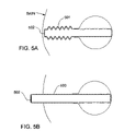
- FIG. 5A is a section view through tissue, schematically showing an alternate sheath embodiment having a convoluted or pleated shaft. The proximal end of the sheath is closed.
- FIG. 5B is a view of the embodiment of FIG. 5A with the proximal end of the convoluted sheath having been accessed through the skin and extended outwardly from the skin of the patient.
- FIG. 6A is a section view through tissue showing an inflated balloon with another embodiment of a sheath having an everted shaft positioned under the skin.
- FIG. 6B is a view of the apparatus of FIG. 6A with the sheath having been accessed and extended, with the eversion thus eliminated and the closed end removed.
- FIG. 6C is a view of the apparatus of FIG. 6B with a conventional hub attached to the proximal end of the sheath, and a source catheter inserted into the sheath and advanced into the balloon.
- a conventional seal has been provided within the hub to allow a suction channel to drain the excision cavity.
- FIGS. 7A and B are section views through body tissue which show an implanted sheath similar to that of FIG. 5A , without a balloon, the sheath being later accessed and drawn outward ( FIG. 7B ) in a way similar to that shown in FIG. 5B .
- FIG. 8A is a section view through body tissue showing a straight sheath implanted under the skin of the patient with its distal end well into the incision cavity following surgery.
- FIG. 8B is a section view of the sheath of FIG. 8A having been reaccessed through the skin of the patient and drawn outwards in much the same manner as the sheath of FIG. 7B .
- FIG. 9 is a section view through tissue showing an implanted sheath of FIG. 7 or 8 , with its closed end removed and with an inner sheath comprising a balloon and hub inserted into the implanted sheath.
- a source catheter is shown within the inner sheath for purposes of irradiating the inside of the incision cavity.
- the method of this invention comprises placing apparatus within or proximate a tumor resection cavity which facilitates easy reaccess to the cavity for brachytherapy.
- apparatus is preferably placed intraoperatively (but could be placed later in a separate procedure) and allows the skin to be closed pending a decision to proceed with, or to abandon brachytherapy.
- This method eliminates the need for apparatus passing through the skin for a protracted period and optionally provides for administration of therapeutic agents or anesthetic during subsequent apparatus manipulation or the brachytherapy treatment itself.
- the embodiments described below are used in conjunction with conventional brachytherapy apparatus.
- the embodiments of the invention generally provide a convenient path for conventional brachytherapy apparatus to be inserted into the resection cavity some protracted time after the resection procedure itself.
- the procedure to reaccess the cavity begins with an incision (or percutaneous stick) to reach a portion of the implanted apparatus which is preferably near the skin of the patient.
- an extension of the apparatus is established which protrudes through the skin at its proximal end, and leads into the resection cavity. Subsequent steps will depend on the invention embodiment chosen, but all lead to facilitating use of conventional brachytherapy methods and/or apparatus to complete the brachytherapy.
- FIG. 1 depicts an apparatus 100 including a simple balloon 101 placed intraoperatively within the body and inflated in an excision cavity.
- the patch can be relatively small compared to the balloon surface, or it can cover a significant portion of the surface.
- Self-sealing patch materials include various gel materials known in the art and silicone elastomers.
- Suitable balloon materials include polyurethanes and silicone rubbers. At one extreme, the material may be selected, and balloons may be designed, which are sufficiently elastic to conform to shape of the excision cavity.
- materials and designs can be chosen which will substantially shape the cavity so that it conforms to a desired configuration, for example, so that it mimics the shape of the isodose surfaces which are generated by the brachytherapy source and apparatus in total and/or which correspond to the planned therapy.
- balloon designs can be devised with properties between these extremes.
- an isotropic point source and spherical balloon filled with an absorber might advantageously be employed to produce a series of spherical isodose surfaces, each surface with decreasing dose at greater and greater radii from the source.
- FIGS. 2A and B depict a balloon 201 having a long radial extension 202 , shaped somewhat like a test tube.
- the length of the extension is greater than the distance between the excision cavity and the skin.
- the balloon can be partially inflated and the extension everted, for example by a rod (not shown), and with the rod removed, placed within the cavity positioned for later access through a cut down procedure or percutaneous stick at a desired location through the skin. See FIG. 2A for this configuration. Palpation may be adequate to locate the extension, or if desired, the skin can be marked for future access, for example by a tattoo dot 210 .
- the balloon can be fully inflated as described with respect to FIG. 1 above so as to maintain the cavity until radiation brachytherapy is commenced.
- the incision is then closed over the brachytherapy balloon apparatus to begin the healing process. No parts of the apparatus protrude through the skin once the incision is closed.
- the balloon extension 202 When irradiation is to begin, the balloon extension 202 is accessed by percutaneous stick or incision, and the balloon extension withdrawn outwardly through the skin as shown in FIG. 2B . Note that balloon pressure will tend to make the extension evert spontaneously.
- the end of the extension can then be manipulated to allow insertion of a radiation source catheter 203 .
- a preferred method is to insert a source catheter with a radiation source 204 at its tip into the extension such that the extension re-everts as the catheter is advanced into the balloon.
- Graduation marks 205 ( FIG. 2C ) on the catheter can be used to accurately position the depth of the catheter within the incision cavity. Such positioning can be confirmed by conventional imaging, and if desired, a clamp (not shown) can be used to secure the catheter within the protruding extension near its point of re-eversion to maintain the source position.
- the extension may be cut off and a conventional hub with internal seal (not shown; similar to that of FIG. 6C ) attached in an appropriate manner to the extension. It may be necessary to reestablish balloon inflation after the catheter is started into the hub and balloon extension. Graduation marks may be used to indicate position of the catheter within the balloon. With the hub seal to maintain inflation pressure integrity, a separate channel (as shown in FIG. 2D , for example) can be provided alongside the balloon extension for inflation.
- FIG. 2D A particularly preferred embodiment is shown in FIG. 2D .
- an inner sheath 206 which in conjunction with the hub, seal and an optional distal balloon centering pocket 207 , facilitates accurate location of the source catheter.
- the inner sheath 206 serves to evert the extension 202 in the same manner as the catheter 203 in FIG. 2C .
- the optional distal centering pocket 207 cooperates with the distal tip of the inner sheath 206 and facilitates proper positioning of the source 204 .
- graduation marks 205 facilitate depth control of the catheter 203 relative to the proximal end of the inner sheath or the hub.
- Inflation of this embodiment is through a tube channel 208 adjacent to the balloon extension 202 , and incorporates an in-line check valve 209 (Halkey-Roberts Corporation, St. Moscow, Fla.).
- Balloons of the nature described in FIGS. 1 and 2 can be fabricated by heat welding polymer sheet, for example polyurethane sheet (Deerfield Urethane, Inc., South Deerfield, Mass.) and subsequently pressure stretched at sufficient temperatures to form the desired shapes. Alternatively, they can be molded or formed from silicone rubber or other suitable polymers. Inflation channels such as that shown in FIG. 2D can be fabricated from tubing and components bonded together.
- FIGS. 3A , B and C depict a balloon 301 bonded to a tubular outer sheath 302 having a closed proximal end 303 .
- the length of the sheath is such that when positioned under the skin in the desired location, the balloon must partially evert inwardly at 307 to accommodate the sheath length.
- FIG. 3A When accessed to commence brachytherapy, the sheath 302 is withdrawn outwardly from the skin and the end 303 is cut off or otherwise removed, as shown in FIG. 3B .
- FIG. 3C shows the end of the sheath cut, and a conventional hub and seal (not shown, see FIG.
- 6C for a representative hub and seal
- An inner sheath 304 is then inserted into the outer sheath and advanced into the balloon.
- a centering pocket 305 may be provided in the distal end of the balloon to locate the tip of the inner sheath. Proper positioning can be verified by conventional imaging. Such provision facilitates accurate location of the radiation catheter 306 which is positioned in the inner sheath 304 for brachytherapy.
- the hub may conveniently incorporate an inflation port for the balloon since a sealed annular lumen is provided between sheaths.
- use of an inner sheath 304 may be eliminated, and catheter 306 may be inserted directly into the outer sheath 302 and advanced into the balloon 301 for brachytherapy treatment.
- FIG. 4A shows a balloon 401 and sheath 402 with a receptacle or housing 403 at the proximal end of the sheath 402 .
- the sheath preferably is secured (for example by bonding) at both the proximal and distal ends of the balloon 401 , and to the distal side of the housing 403 .
- the sheath length is substantially fixed compared to the apparatus previously described with respect to that of FIGS. 2 and 3 .
- the housing 403 is divided into two sections, a larger section 404 for the radiation source catheter (not shown), and a smaller for syringe access to a balloon inflation channel 405 positioned alongside the source catheter channel 406 .
- the housing may further comprise features which provide tactile feedback from outside of the patient's skin to assist locating and identifying individual channels, facilitating percutaneous access. Such features would include sized, positioned or shaped openings, or protrusions which can be felt by hand.
- Both housing sections are filled with self sealing gel or silicone rubber 407 as described previously, and both are tapered or beveled such that a syringe 408 in the case of inflation, or a sheath extension for purposes of creating convenient source catheter access, can be guided into proper engagement with their respective channels percutaneously, or with the help of a cut-down procedure.
- Ring-like or other appendages or flanges with holes 411 are molded onto the exterior of the housing to facilitate suturing the housing to the skin.
- An inflation syringe 408 is shown inflating the balloon.
- Sutures are shown fastening the housing 403 to the patient's skin, an exemplary suture 410 from without the patient, and another suture 409 from within. Either approach may be used, and suturing may be through the entirety of the skin, or may be (from the inside) only through the subcutaneous layer.
- FIG. 4B shows a detail of the inflation channel 405 distal of the housing 403 . If the self sealing material is not strong enough to maintain inflation of the balloon, a valve 412 may be provided to maintain inflation.
- the valve illustrated in FIG. 4B is a conventional flapper type check valve on a molded live hinge, with syringe needle S shown holding it in an open position.
- FIG. 4C shows a detail of the housing 403 in section, with a female tapered bore 413 to accept a male taper 414 of a split-tip trocar style sheath extension 415 .
- the sheath extension 415 is shown entering the bore, to seat in the source catheter channel 406 behind the receptacle or housing 403 .
- FIG. 4D shows the trocar extension seated (if necessary, with removal of self-sealing material 407 to facilitate the seating) and the tip 416 spread open by the source catheter 417 advancing toward the balloon (not shown) through the source catheter channel 406 in the outer sheath 402 .
- FIG. 5A depicts an alternate sheath design with a convoluted or pleated extendable shaft 501 .
- the proximal end 502 of the sheath 501 may be grasped, extended and withdrawn free of the skin as shown in FIG. 5B , and treated similarly to the sheath 302 of FIG. 3 , including cutting off the end 502 .
- the sheath can be elastomeric, and stretched to mimic the sheath of, for example, FIGS. 2A-2D .
- FIG. 6A shows a balloon 601 and sheath 602 with an everted section 603 outside the balloon, such that the sheath section 603 folds over itself in coaxial configuration.
- the sheath 602 extends through the length of the balloon 601 and in this embodiment is fastened at its distal end (as by bonding for example) to the distal end of the balloon 601 . After a cutdown, this sheath can be withdrawn and everted such that the proximal end of the sheath extends free of the skin as shown in FIG. 6B .
- This embodiment too too can be fitted with a hub 604 , for example by threads 610 , and with an internal seal 605 for the source catheter 606 , as shown in FIG. 6C .
- a threaded cap (not shown) can be provided which can be removed in order to fix the hub 604 to the sheath 602 .
- the annulus between the sheath 602 and the catheter 606 is utilized for suction from within the incision cavity for seroma and the like, as indicated by the arrows 607 at the distal end of the balloon 601 , and adjacent to the proximal end of the balloon. Suction applied at the arrow 608 will serve to evacuate the excision cavity.
- 10/683,885 both referenced above, can be used to provide distributed suction capability over the surface of the balloon 601 .
- the suction channel can be reversed, again according to the teachings of Ser. No. 11/639,495, the channel can be used to infuse therapeutic or anesthetic agents into the cavity outside of the balloon 601 , or outside the shaft 602 .
- Anaesthetic can be administered to ease discomfort of the patient on removal of the applicator or on inflation of the balloon or re-inflation.
- a second auxiliary port can be provided on the hub 604 communicating with a small lumen within the wall of the sheath (not shown) in a conventional manner. Arrows 609 indicate this channel.
- FIG. 7A shows schematically an implanted, convoluted sheath 701 without balloon positioned between incision cavity 704 and the skin of the patient.
- the sheath 701 has a closed proximal end 702 .
- FIG. 7B shows the sheath 701 of FIG. 7A having been reaccessed by cut down through the skin or other means, and drawn outward. Once proud of the skin, the closed end 702 is then removed, providing open access to the incision cavity for inserting of further brachytherapy apparatus into the cavity, preferably a conventional applicator and miniature x-ray source (now shown), and subsequent radiotherapy.
- a hub (not shown) may be used as in preceding embodiments if desired.
- FIGS. 8A and 8B schematically show a similar sheath 803 apparatus to that of FIG. 7A , but rather than having a convoluted shaft, the sheath is straight and extends well into the cavity 804 when contained under the skin.
- the incision is closed in the manner described above, and the incision cavity allowed to collapse around the implanted sheath during the healing process.
- FIG. 8B shows the sheath 803 having been reaccessed and partially withdrawn above the skin such that the closed end 802 can be removed, all without losing access to the incision cavity 804 .
- radiotherapy commences in the manner described above in connection with FIGS. 7A and 7B .
- FIG. 9 depicts schematically an apparatus 900 comprising an implanted sheath structure 901 of FIG. 7 or 8 , but in addition, an inner sheath 902 having a balloon 903 proximal of its distal end has been inserted into an incision cavity 904 .
- a hub 905 is affixed, for example by bonding, and provides balloon inflation through a port 906 at the upper hub arm, and through a conventional port and lumen (neither shown) within the wall of the inner sheath 902 .
- the hub 905 also provides suction (see flow arrow 907 ) through the annulus between the sheaths 901 and 902 though a port 908 at the lower arm of the hub 905 and sheath ports 909 near the proximal end of the balloon 903 in the inner sheath 902 .
- a seal 912 at the proximal end of the sheath 901 provides pressure integrity for the suction channel. Reversing this fluid circuit will provide for infusion of therapeutic agents or anesthetic.
- a source catheter 910 is inserted having a source 911 at its distal tip.
- Radiation attenuating patches or balloon segments, or spacers, placed on or adjacent to balloons of the implanted apparatus can be used locally to moderate radiation intensity, thus tailoring radiation output to variations in anatomy or prescription.
- Such radiation moderating devices are discussed in co-pending application Ser. No. 11/385,255, filed Mar. 20, 2006, the specification of which is incorporated herein in its entirety.
- Each embodiment described preferably includes a portion of the applicator apparatus which, when reaccessed for radiotherapy, establishes an extension outside the skin that facilitates creation of an infection barrier for the duration of the prescribed therapy.
Abstract
Description
Claims (16)
Priority Applications (4)
| Application Number | Priority Date | Filing Date | Title |
|---|---|---|---|
| US11/871,116 US7727137B2 (en) | 2006-10-13 | 2007-10-11 | Balloon brachytherapy applicator and method |
| EP07839535A EP2077899B1 (en) | 2006-10-13 | 2007-10-12 | Balloon brachytherapy applicator |
| AT07839535T ATE509663T1 (en) | 2006-10-13 | 2007-10-12 | BALLOON BRACHYTHERAPY APPLICATOR |
| PCT/US2007/021937 WO2008048521A2 (en) | 2006-10-13 | 2007-10-12 | Balloon brachytherapy applicator and method |
Applications Claiming Priority (2)
| Application Number | Priority Date | Filing Date | Title |
|---|---|---|---|
| US85168706P | 2006-10-13 | 2006-10-13 | |
| US11/871,116 US7727137B2 (en) | 2006-10-13 | 2007-10-11 | Balloon brachytherapy applicator and method |
Publications (2)
| Publication Number | Publication Date |
|---|---|
| US20090209802A1 US20090209802A1 (en) | 2009-08-20 |
| US7727137B2 true US7727137B2 (en) | 2010-06-01 |
Family
ID=39314619
Family Applications (1)
| Application Number | Title | Priority Date | Filing Date |
|---|---|---|---|
| US11/871,116 Active 2028-04-09 US7727137B2 (en) | 2006-10-13 | 2007-10-11 | Balloon brachytherapy applicator and method |
Country Status (4)
| Country | Link |
|---|---|
| US (1) | US7727137B2 (en) |
| EP (1) | EP2077899B1 (en) |
| AT (1) | ATE509663T1 (en) |
| WO (1) | WO2008048521A2 (en) |
Cited By (1)
| Publication number | Priority date | Publication date | Assignee | Title |
|---|---|---|---|---|
| US9662511B2 (en) | 2012-11-05 | 2017-05-30 | Nucletron Operations B.V. | Methods of making a medical applicator |
Families Citing this family (15)
| Publication number | Priority date | Publication date | Assignee | Title |
|---|---|---|---|---|
| DE102008030590A1 (en) | 2007-06-29 | 2009-01-08 | Carl Zeiss Surgical Gmbh | Radiotherapy device applicator for treating tumor in spinal column of patient, has base plate with base area, and guiding area connected to base plate, where diameter of guiding area is smaller or equal to diameter of base area |
| WO2009027394A1 (en) * | 2007-08-29 | 2009-03-05 | Acrostak Corp. | Method and kit for delivery of brachytherapy to a subject |
| US8944984B2 (en) * | 2008-03-11 | 2015-02-03 | Kevin Armstrong | Radiation/drug delivery method and apparatus |
| US8636635B2 (en) * | 2008-08-18 | 2014-01-28 | Cianna Medical, Inc. | Brachytherapy apparatus, systems, and methods for using them |
| US20100331878A1 (en) * | 2009-06-25 | 2010-12-30 | Carl Zeiss Surgical Gmbh | Method and device for removing a balloon from a body cavity |
| DE102009058581A1 (en) * | 2009-12-17 | 2011-06-22 | Carl Zeiss Surgical GmbH, 73447 | Applicator device for radiotherapy, fastening device and radiotherapy device |
| DE102009058777A1 (en) * | 2009-12-18 | 2011-06-22 | Carl Zeiss Surgical GmbH, 73447 | Applicator device for radiotherapy and radiotherapy device |
| US20150190621A1 (en) * | 2012-09-11 | 2015-07-09 | University Of Florida Research Foundation, Incorporated | Device and Method for Tissue Displacement in Brachytherapy |
| JP6575013B2 (en) | 2012-12-21 | 2019-09-18 | ピアブ・アクチエボラグ | Vacuum ejector nozzle with elliptical divergent section |
| GB2509183A (en) | 2012-12-21 | 2014-06-25 | Xerex Ab | Vacuum ejector with tripped diverging exit flow nozzle |
| GB2509184A (en) * | 2012-12-21 | 2014-06-25 | Xerex Ab | Multi-stage vacuum ejector with moulded nozzle having integral valve elements |
| GB2509182A (en) | 2012-12-21 | 2014-06-25 | Xerex Ab | Vacuum ejector with multi-nozzle drive stage and booster |
| GB201418117D0 (en) | 2014-10-13 | 2014-11-26 | Xerex Ab | Handling device for foodstuff |
| CN105920727A (en) * | 2016-04-11 | 2016-09-07 | 王娟 | Radioactive particle chain and use method thereof |
| CN116440428B (en) * | 2023-06-12 | 2023-08-22 | 北京普朗盾医疗科技有限公司 | Implantable tissue isolation device capable of being repeatedly charged and discharged in vivo |
Citations (20)
| Publication number | Priority date | Publication date | Assignee | Title |
|---|---|---|---|---|
| US4706652A (en) * | 1985-12-30 | 1987-11-17 | Henry Ford Hospital | Temporary radiation therapy |
| US4871358A (en) | 1987-11-09 | 1989-10-03 | Gold Steven K | Externally-based inversionary tube |
| US5566221A (en) | 1994-07-12 | 1996-10-15 | Photoelectron Corporation | Apparatus for applying a predetermined x-radiation flux to an interior surface of a body cavity |
| US5611767A (en) * | 1991-06-14 | 1997-03-18 | Oncocath, Inc. | Radiation treatment of tumors using inflatable devices |
| US5748699A (en) | 1995-10-06 | 1998-05-05 | Smith; Donald O. | Apparatus for applying X-rays to an interior surface of a body cavity |
| US5797886A (en) * | 1994-02-18 | 1998-08-25 | Merit Medical Systems, Inc. | Catheter apparatus with means for subcutaneous delivery of anesthetic agent or other fluid medicament |
| US5947953A (en) | 1997-08-06 | 1999-09-07 | Hemocleanse, Inc. | Splittable multiple catheter assembly and methods of inserting the same |
| US6213973B1 (en) | 1998-01-12 | 2001-04-10 | C. R. Bard, Inc. | Vascular access port with elongated septum |
| US6319188B1 (en) | 1999-04-26 | 2001-11-20 | Xoft Microtube, Inc. | Vascular X-ray probe |
| US20010049502A1 (en) * | 1998-11-25 | 2001-12-06 | Light Sciences Corporation | Guide sheath for repeated placement of a device |
| US6364892B1 (en) | 1992-06-02 | 2002-04-02 | General Surgical Innovations, Inc. | Ballon dissector with improved visualization |
| US6540764B1 (en) | 1992-06-02 | 2003-04-01 | General Surgical Innovations, Inc. | Apparatus and method for dissecting tissue layers |
| US20040116767A1 (en) * | 2002-09-10 | 2004-06-17 | Lebovic Gail S. | Brachytherapy apparatus and methods of using same |
| US20040245483A1 (en) * | 2001-05-15 | 2004-12-09 | Smit Berend Jakobus | Radiation application method and device |
| US20050101860A1 (en) | 2003-11-07 | 2005-05-12 | Proxima Therapeutics, Inc. | Tissue positioning systems and methods for use with radiation therapy |
| US6923754B2 (en) * | 2002-11-06 | 2005-08-02 | Senorx, Inc. | Vacuum device and method for treating tissue adjacent a body cavity |
| US6987835B2 (en) | 2003-03-26 | 2006-01-17 | Xoft Microtube, Inc. | Miniature x-ray tube with micro cathode |
| US20060100475A1 (en) | 2004-11-05 | 2006-05-11 | White Jack C | Expandable brachytherapy device |
| US20060206178A1 (en) | 2005-03-11 | 2006-09-14 | Kim Daniel H | Percutaneous endoscopic access tools for the spinal epidural space and related methods of treatment |
| US20070270627A1 (en) * | 2005-12-16 | 2007-11-22 | North American Scientific | Brachytherapy apparatus for asymmetrical body cavities |
-
2007
- 2007-10-11 US US11/871,116 patent/US7727137B2/en active Active
- 2007-10-12 WO PCT/US2007/021937 patent/WO2008048521A2/en active Application Filing
- 2007-10-12 EP EP07839535A patent/EP2077899B1/en not_active Not-in-force
- 2007-10-12 AT AT07839535T patent/ATE509663T1/en not_active IP Right Cessation
Patent Citations (21)
| Publication number | Priority date | Publication date | Assignee | Title |
|---|---|---|---|---|
| US4706652A (en) * | 1985-12-30 | 1987-11-17 | Henry Ford Hospital | Temporary radiation therapy |
| US4871358A (en) | 1987-11-09 | 1989-10-03 | Gold Steven K | Externally-based inversionary tube |
| US5611767A (en) * | 1991-06-14 | 1997-03-18 | Oncocath, Inc. | Radiation treatment of tumors using inflatable devices |
| US6364892B1 (en) | 1992-06-02 | 2002-04-02 | General Surgical Innovations, Inc. | Ballon dissector with improved visualization |
| US7179272B2 (en) | 1992-06-02 | 2007-02-20 | General Surgical Innovations, Inc. | Apparatus and method for dissecting tissue layers |
| US6540764B1 (en) | 1992-06-02 | 2003-04-01 | General Surgical Innovations, Inc. | Apparatus and method for dissecting tissue layers |
| US5797886A (en) * | 1994-02-18 | 1998-08-25 | Merit Medical Systems, Inc. | Catheter apparatus with means for subcutaneous delivery of anesthetic agent or other fluid medicament |
| US5566221A (en) | 1994-07-12 | 1996-10-15 | Photoelectron Corporation | Apparatus for applying a predetermined x-radiation flux to an interior surface of a body cavity |
| US5748699A (en) | 1995-10-06 | 1998-05-05 | Smith; Donald O. | Apparatus for applying X-rays to an interior surface of a body cavity |
| US5947953A (en) | 1997-08-06 | 1999-09-07 | Hemocleanse, Inc. | Splittable multiple catheter assembly and methods of inserting the same |
| US6213973B1 (en) | 1998-01-12 | 2001-04-10 | C. R. Bard, Inc. | Vascular access port with elongated septum |
| US20010049502A1 (en) * | 1998-11-25 | 2001-12-06 | Light Sciences Corporation | Guide sheath for repeated placement of a device |
| US6319188B1 (en) | 1999-04-26 | 2001-11-20 | Xoft Microtube, Inc. | Vascular X-ray probe |
| US20040245483A1 (en) * | 2001-05-15 | 2004-12-09 | Smit Berend Jakobus | Radiation application method and device |
| US20040116767A1 (en) * | 2002-09-10 | 2004-06-17 | Lebovic Gail S. | Brachytherapy apparatus and methods of using same |
| US6923754B2 (en) * | 2002-11-06 | 2005-08-02 | Senorx, Inc. | Vacuum device and method for treating tissue adjacent a body cavity |
| US6987835B2 (en) | 2003-03-26 | 2006-01-17 | Xoft Microtube, Inc. | Miniature x-ray tube with micro cathode |
| US20050101860A1 (en) | 2003-11-07 | 2005-05-12 | Proxima Therapeutics, Inc. | Tissue positioning systems and methods for use with radiation therapy |
| US20060100475A1 (en) | 2004-11-05 | 2006-05-11 | White Jack C | Expandable brachytherapy device |
| US20060206178A1 (en) | 2005-03-11 | 2006-09-14 | Kim Daniel H | Percutaneous endoscopic access tools for the spinal epidural space and related methods of treatment |
| US20070270627A1 (en) * | 2005-12-16 | 2007-11-22 | North American Scientific | Brachytherapy apparatus for asymmetrical body cavities |
Non-Patent Citations (5)
| Title |
|---|
| Ashpole et al., R.D., "A New Technique of Brachytherapy for Malignant Gliomas with Caesium 137: A New Method Utilizing a New Afterloading System", Clinical Oncology, vol. 2, (1990), pp. 333-337. |
| Jobson et al., J.J., "Timing of Radiotherapy and Survival Benefit in Breast Cancer", Breast Cancer Research and Treatment, (2006) 99:289-294. |
| Low-Beer, B.V.A., "The Clinical Use of Radioisotopes", Charles C. Thomas Publ., 1950, pp. 343-349. |
| Muller, J.H., "Radiotherapy of Bladder Cancer by Means of Rubber Balloons Filled In Situ with Solutions of a Radioactive Isotope (Co60)", Cancer, Sep.-Oct. 1995, pp. 1035-1043. |
| Smitt & Kirby, "Dose-Volume Characteristics of a 50-kV Electronic Brachytherapy Source" Brachytherapy , 6 (2007), 207-211. |
Cited By (1)
| Publication number | Priority date | Publication date | Assignee | Title |
|---|---|---|---|---|
| US9662511B2 (en) | 2012-11-05 | 2017-05-30 | Nucletron Operations B.V. | Methods of making a medical applicator |
Also Published As
| Publication number | Publication date |
|---|---|
| EP2077899A2 (en) | 2009-07-15 |
| ATE509663T1 (en) | 2011-06-15 |
| US20090209802A1 (en) | 2009-08-20 |
| EP2077899B1 (en) | 2011-05-18 |
| WO2008048521A2 (en) | 2008-04-24 |
| WO2008048521A3 (en) | 2008-08-21 |
| EP2077899A4 (en) | 2010-01-27 |
Similar Documents
| Publication | Publication Date | Title |
|---|---|---|
| US7727137B2 (en) | Balloon brachytherapy applicator and method | |
| US8137256B2 (en) | Brachytherapy apparatus | |
| US5720717A (en) | Intracavitary catheter for use in therapeutic radiation procedures | |
| EP0934094B1 (en) | Inflatable devices for tumor treatment | |
| US8636635B2 (en) | Brachytherapy apparatus, systems, and methods for using them | |
| US7524274B2 (en) | Tissue positioning systems and methods for use with radiation therapy | |
| US7744521B2 (en) | Customized gynecological brachytherapy applicator and method | |
| US11944844B2 (en) | Internal body cavity therapeutic applicators and methods for using them | |
| US8226539B2 (en) | Brachytherapy apparatus for asymmetrical body cavities | |
| US7783006B2 (en) | Radiation treatment using x-ray source | |
| US8328711B2 (en) | Selectable multi-lumen brachytherapy devices and methods | |
| US7678040B2 (en) | Customized gynecological brachytherapy applicator and method | |
| JP5952824B2 (en) | Extended brachytherapy device and method of use thereof | |
| EP1682225B1 (en) | Drug eluting brachytherapy apparatus | |
| CN117504161A (en) | Physical partition device for protecting adjacent organs during radiotherapy | |
| US20090156879A1 (en) | Selectable Multi-Lumen Brachytherapy Devices and Methods | |
| MXPA06005352A (en) | Drug eluting brachytherapy methods and apparatus |
Legal Events
| Date | Code | Title | Description |
|---|---|---|---|
| AS | Assignment |
Owner name: XOFT, INC., CALIFORNIA Free format text: ASSIGNMENT OF ASSIGNORS INTEREST;ASSIGNORS:FRANCESCATTI, DARIUS;HOFFMANN, DAVID J.;TREMBERTH, SCOTT;AND OTHERS;REEL/FRAME:022644/0016;SIGNING DATES FROM 20090305 TO 20090310 Owner name: XOFT, INC.,CALIFORNIA Free format text: ASSIGNMENT OF ASSIGNORS INTEREST;ASSIGNORS:FRANCESCATTI, DARIUS;HOFFMANN, DAVID J.;TREMBERTH, SCOTT;AND OTHERS;SIGNING DATES FROM 20090305 TO 20090310;REEL/FRAME:022644/0016 |
|
| STCF | Information on status: patent grant |
Free format text: PATENTED CASE |
|
| AS | Assignment |
Owner name: EASTON CAPITAL PARTNERS, L.P., NEW YORK Free format text: SECURITY AGREEMENT;ASSIGNOR:XOFT, INC.;REEL/FRAME:025114/0354 Effective date: 20101008 |
|
| AS | Assignment |
Owner name: XOFT, INC., CALIFORNIA Free format text: RELEASE BY SECURED PARTY;ASSIGNOR:EASTON CAPITAL PARTNERS, L.P.;REEL/FRAME:025558/0311 Effective date: 20101229 |
|
| FEPP | Fee payment procedure |
Free format text: PAYOR NUMBER ASSIGNED (ORIGINAL EVENT CODE: ASPN); ENTITY STATUS OF PATENT OWNER: SMALL ENTITY |
|
| FPAY | Fee payment |
Year of fee payment: 4 |
|
| MAFP | Maintenance fee payment |
Free format text: PAYMENT OF MAINTENANCE FEE, 8TH YR, SMALL ENTITY (ORIGINAL EVENT CODE: M2552) Year of fee payment: 8 |
|
| AS | Assignment |
Owner name: WESTERN ALLIANCE BANK, CALIFORNIA Free format text: SECURITY INTEREST;ASSIGNOR:XOFT, INC.;REEL/FRAME:052916/0197 Effective date: 20200330 |
|
| MAFP | Maintenance fee payment |
Free format text: PAYMENT OF MAINTENANCE FEE, 12TH YR, SMALL ENTITY (ORIGINAL EVENT CODE: M2553); ENTITY STATUS OF PATENT OWNER: SMALL ENTITY Year of fee payment: 12 |
|
| AS | Assignment |
Owner name: XOFT, INC., CALIFORNIA Free format text: RELEASE BY SECURED PARTY;ASSIGNOR:WESTERN ALLIANCE BANK;REEL/FRAME:065191/0827 Effective date: 20210505 |
|
| AS | Assignment |
Owner name: NUCLETRON OPERATIONS B.V., NETHERLANDS Free format text: ASSIGNMENT OF ASSIGNORS INTEREST;ASSIGNOR:XOFT SOLUTIONS, LLC;REEL/FRAME:065573/0319 Effective date: 20231022 |