US7733802B2 - Method to dynamically create a virtual network - Google Patents
Method to dynamically create a virtual network Download PDFInfo
- Publication number
- US7733802B2 US7733802B2 US11/228,868 US22886805A US7733802B2 US 7733802 B2 US7733802 B2 US 7733802B2 US 22886805 A US22886805 A US 22886805A US 7733802 B2 US7733802 B2 US 7733802B2
- Authority
- US
- United States
- Prior art keywords
- network
- new virtual
- virtual network
- controller
- request
- Prior art date
- Legal status (The legal status is an assumption and is not a legal conclusion. Google has not performed a legal analysis and makes no representation as to the accuracy of the status listed.)
- Expired - Fee Related, expires
Links
Images


Classifications
-
- H—ELECTRICITY
- H04—ELECTRIC COMMUNICATION TECHNIQUE
- H04L—TRANSMISSION OF DIGITAL INFORMATION, e.g. TELEGRAPHIC COMMUNICATION
- H04L12/00—Data switching networks
- H04L12/28—Data switching networks characterised by path configuration, e.g. LAN [Local Area Networks] or WAN [Wide Area Networks]
- H04L12/46—Interconnection of networks
- H04L12/4641—Virtual LANs, VLANs, e.g. virtual private networks [VPN]
Definitions
- This invention relates generally to data communication, and more specifically to a method to create a virtual network.
- WLAN wireless local area network
- WLAN Wireless Local Area Network
- SSID Service Set Identity
- a network node would discover these pre-configured networks and chooses to join one of the networks.
- the above illustrates a need for a method to create a WLAN virtual network dynamically, with automated configuration for the new WLAN virtual network to function.
- the present invention addresses such a need.
- a method creates a virtual network dynamically, with automated configuration for the new virtual network to function.
- the virtual network creation is initiated by a network node sending a request for a virtual network to a network controller.
- the network controller services the request, creating the virtual network by automatically configuring at least one network switch in the physical network.
- the network controller automatically determines a configuration for the virtual network using virtual network information, and creates the virtual network by configuring network switches according to the configuration.
- the virtual network can be configured for particular applications. From a user's point of view, the user connects to a network node.
- the network node then initiates the creation of the virtual network transparently to the user. The resource-intensive manual configurations of the conventional approach in creating new virtual networks are thus avoided.
- FIG. 1 illustrates a virtual network in accordance with the present invention.
- FIG. 2 illustrates a process for creating a virtual network in accordance with the present invention.
- FIG. 3 illustrates a process for creating a virtual network with a plurality of network switches in accordance with the present invention.
- FIG. 4 illustrates a process for creating a virtual wireless network in accordance with the present invention.
- FIG. 5 illustrates a process for creating a virtual wireless network with a plurality of wireless network switches in accordance with the present invention.
- FIG. 6 illustrates a process for creating a virtual Ethernet network in accordance with the present invention.
- FIG. 7 illustrates a process for creating a virtual Ethernet network with a plurality of Ethernet network switches in accordance with the present invention.
- the method in accordance with the present invention creates a virtual network dynamically, with automated configuration for the new virtual network to function.
- the virtual network creation is initiated by a network node sending a request for a virtual network to a network controller.
- the network controller services the request, creating the virtual network by automatically configuring at least one network switch in the physical network. The resource-intensive manual configurations of the conventional approach in creating new virtual networks are avoided.
- FIG. 1 illustrates a virtual network in accordance with the present invention.
- a virtual network includes a network switch 130 and a plurality of network nodes 110 , 120 .
- a network node 110 communicates with another network node 120 by sending and receiving network packets.
- a network node 110 sends network packets to a network switch 130 , and receives network packets from a network switch 130 . If one network node 110 , sending network packets, and another network node 120 , receiving network packets, connect to a same network switch 130 , the network switch 130 switches network packets received from network node 110 to network node 120 .
- a virtual network is based on wired communication technologies such as Ethernet.
- a virtual network is based on wireless communication technologies such as radio frequency technology. Other types of communication technologies are possible.
- a configuration for a virtual network includes virtual network properties.
- virtual network properties include a network name, or derive a network name.
- virtual network properties include security information such as an encryption key.
- virtual network properties include quality of services, bandwidth parameters, classes of services.
- a network switch 130 requires configuration for a virtual network in order for the network switch 130 to process network packets in the virtual network.
- Any network node 110 , 120 may connect to a plurality of virtual networks and other networks.
- Network packets for different virtual networks may have different network names.
- FIG. 2 illustrates a process for creating a virtual network in accordance with the present invention.
- a network node 210 initiates a process to create a virtual network by sending a request for a virtual network creation.
- a network switch 230 receives the request and sends the request to a network controller 240 .
- the request includes virtual network information.
- Virtual network information includes any information required by the network controller 240 to configure and create the requested virtual network, such as network name, network usage or network configuration, etc.
- network controller 240 prompts network node 210 for virtual network information. The network controller 240 then services the request.
- network controller 240 determines the virtual network requested does not exist, and proceeds to create the virtual network. In another embodiment, network controller 240 examines the virtual network information in the request, and proceeds to create the virtual network without first determining if the virtual network requested exists.
- network controller 240 determines the configuration for the virtual network.
- virtual network information includes the configuration.
- network controller 240 uses virtual network information to determine the configuration.
- network controller 240 determines the configuration using information provided by a network database (not shown).
- Network controller 240 configures network switch 230 using the configuration.
- the configuration may include one or more virtual network properties described above.
- network switch 230 can accept network packets of the virtual network.
- Network controller 240 replies to network node 210 .
- Network node 210 receives the response from network controller 240 and can then also send network packets onto the virtual network.
- FIG. 3 illustrates a process for creating a virtual network with a plurality of network switches in accordance with the present invention.
- a network node 310 initiates a process to create a virtual network.
- a network switch 330 receives the request and sends the request to a network controller 340 .
- the request includes virtual network information as defined above.
- network controller 340 prompts network node 310 for virtual network information. The network controller 340 then services the request.
- network controller 340 determines the virtual network requested does not exist, and proceeds to create the virtual network. In another embodiment, network controller 340 examines the virtual network information in the request, and proceeds to create the virtual network without first determining if the virtual network requested exists.
- network controller 340 determines the configuration for the virtual network.
- virtual network information includes the configuration.
- network controller 340 uses virtual network information to determine the configuration.
- network controller 340 determines the configuration using information provided by a network database (not shown).
- the plurality of network switches includes network switches 330 and 332 .
- Network controller 340 configures network switches 330 and 332 using the configuration.
- the configuration may include one or more virtual network properties described above.
- Network controller 340 may configure other network switches (not shown) as well depending on the configuration.
- network switches 330 and 332 can accept network packets of the virtual network.
- Network controller 340 replies to network node 310 .
- Network node 310 receives the response from the network controller, and can start sending network packets onto the virtual network.
- a network node 312 connected to network switch 332 can send network packets onto the virtual network.
- Network nodes 310 and 312 can communicate with each other via network switches 330 and 332 .
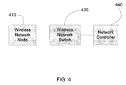
- FIG. 4 illustrates a process for creating a virtual wireless network in accordance with the present invention.
- a wireless network node 410 connects to a wireless network switch 430 through a wireless means, for example radio frequency communication channels.
- a wireless network node 410 initiates a process to create a virtual wireless network by sending a request for a virtual wireless network creation, using a configured communication channel to a network controller 440 .
- the configured communication channel includes network switch 430 .
- the configured communication channel is a wired means such as Ethernet.
- the request includes virtual wireless network information as defined above.
- network controller 440 prompts wireless network node 410 for virtual wireless network information. The network controller 440 then services the request.
- network controller 440 determines the virtual wireless network requested does not exist, and proceeds to create the virtual wireless network. In another embodiment, network controller 440 examines the virtual wireless network information in the request, and proceeds to create the virtual wireless network without first determining if the virtual network requested exists.
- network controller 440 determines the configuration for the virtual wireless network.
- virtual wireless network information includes the configuration.
- network controller 440 uses virtual wireless network information to determine the configuration.
- network controller 440 determines the configuration using information provided by a network database (not shown).
- Network controller 440 configures wireless network switch 430 using the configuration.
- the configuration may include one or more virtual network properties described above.
- wireless network switch 430 can accept network packets of the virtual wireless network.
- Network controller 440 replies to wireless network node 410 .
- Wireless network node 410 receives the response from network controller 440 and can send network packets onto the virtual wireless network.
- FIG. 5 illustrates a process for creating a virtual wireless network with a plurality of wireless network switches in accordance with the present invention.
- a wireless network node 510 initiates a process to create a virtual wireless network by sending a request for a virtual wireless network creation, using a configured communication channel to a network controller 540 .
- the configured communication channel includes network switch 530 .
- the configured communication channel is a wired means such as Ethernet.
- the request includes virtual wireless network information as defined above.
- network controller 540 prompts wireless network node 510 for virtual wireless network information. The network controller 540 then services the request.
- network controller 540 determines the virtual wireless network requested does not exist, and proceeds to create the virtual wireless network. In another embodiment, network controller 540 examines the virtual wireless network information in the request, and proceeds to create the virtual wireless network without first determining if the virtual network requested exists.
- network controller 540 determines the configuration for the virtual wireless network.
- virtual wireless network information includes the configuration.
- network controller 540 uses virtual wireless network information to determine the configuration.
- network controller 540 determines the configuration using information provided by a network database (not shown).
- the plurality of network switches includes wireless network switches 530 and 532 .
- Network controller 540 configures wireless network switches 530 and 532 using the configuration. The configuration may include one or more virtual network properties described above. Network controller 540 may configure other network switches (not shown) as well depending on the configuration.
- wireless network switches 530 and 532 can accept network packets of the virtual wireless network.
- Network controller 540 replies to wireless network node 510 .
- Wireless network node 510 receives the response from the network controller and can start sending network packets onto the virtual wireless network.
- a wireless network node 512 connected to wireless network switch 532 can send network packets onto the virtual wireless network.
- Wireless network nodes 510 and 512 can communicate with each other via network switches 530 and 532 .
- the wireless network is a home wireless network based on WiFi technology.
- the network name is a Service Set Identity (SSID).
- a wireless network switch includes an access point for the home wireless network.
- the home wireless network has an existing Service Set Identity (SSID).
- a wireless network node uses an existing SSID as a configured communication channel to send a request for a virtual wireless network creation to a network controller.
- the network controller determines a SSID of the virtual wireless network.
- the network controller configures the wireless network switches with the SSID of the virtual wireless network. After the wireless network node receives a response from the network controller, the wireless network node can send network packets to the virtual wireless network, using the SSID of the virtual wireless network.
- FIG. 6 illustrates a process for creating a virtual Ethernet network in accordance with the present invention.
- An Ethernet network node 610 connects to an Ethernet network switch 630 through an Ethernet connection.
- the network name of a virtual Ethernet network is a Virtual Local Area Network Identity (VLAN-ID).
- Ethernet network node 610 initiates a process to create a virtual Ethernet network by sending a request for a virtual Ethernet network creation, using the Ethernet connection as a configured communication channel to a network controller 640 .
- Ethernet network node 610 sends the request in an Ethernet broadcast message.
- Ethernet network node 610 sends the Ethernet broadcast message using a specific VLAN-ID, e.g. VLAN-ID 0 .
- Ethernet network node 610 sends the request in an Ethernet unicast message using a specific Media Access Control (MAC) address for network creation. In one embodiment, Ethernet network node 610 sends the request in an Ethernet unicast message using a MAC address for network controller 640 . In one embodiment, Ethernet network node 610 sends the request in an Internet Protocol (IP) message. In one embodiment, the IP message is an IP broadcast message. In one embodiment, the IP message is destined for network controller 640 . In one embodiment, the request includes virtual Ethernet network information. In one embodiment, network controller 640 prompts Ethernet network node 610 for virtual Ethernet network information. The network controller 640 then services the request.
- IP Internet Protocol
- network controller 640 determines the virtual Ethernet network requested does not exist, and proceeds to create the virtual Ethernet network. In another embodiment, network controller 640 examines the virtual Ethernet network information in the request, and proceeds to create the virtual Ethernet network without first determining if the virtual network requested exists. In creating the virtual network, network controller 640 determines the configuration for the virtual Ethernet network. In one embodiment, virtual Ethernet network information includes the configuration. In another embodiment, network controller 640 uses virtual Ethernet network information to determine the configuration. In another embodiment, network controller 640 determines the configuration using information provided by a network database (not shown).
- Network controller 640 configures Ethernet network switch 630 using the configuration.
- the configuration may include one or more virtual network properties described above.
- network controller 640 configures Ethernet network switch 630 with the VLAN-ID of the virtual Ethernet network.
- Ethernet network switch 630 configures Ethernet network switch 630 with a VLAN mapping method.
- the VLAN mapping method is based on MAC address mapping with network controller 640 configuring Ethernet network switch 630 with a MAC address of network node 610 .
- VLAN mapping method is based on port mapping with network controller 640 configuring Ethernet network switch 630 with the Ethernet port at Ethernet network switch 630 that connects to Ethernet network node 610 .
- Ethernet network switch 630 can accept network packets of the virtual Ethernet network.
- Network controller 640 replies to Ethernet network node 610 .
- Ethernet network node 610 receives the response from network controller 640 and can send network packets onto the virtual Ethernet network.
- FIG. 7 illustrates a process for creating a virtual Ethernet network with a plurality of Ethernet network switches in accordance with the present invention.
- An Ethernet network node 710 connects to an Ethernet network switch 730 through an Ethernet connection.
- Ethernet network node 710 initiates a process to create a virtual Ethernet network by sending a request for a virtual Ethernet network creation, using the Ethernet connection as a configured communication channel to a network controller 740 .
- Ethernet network node 710 sends the request in an Ethernet broadcast message.
- Ethernet network node 710 sends the Ethernet broadcast message using a specific VLAN-ID, e.g. VLAN-ID 0 .
- Ethernet network node 710 sends the request in an Ethernet unicast message using a specific Media Access Control (MAC) address for network creation. In one embodiment, Ethernet network node 710 sends the request in an Ethernet unicast message using a MAC address for network controller 740 . In another embodiment, Ethernet network node 710 sends the request in an Internet Protocol (IP) message. In one embodiment, the IP message is an IP broadcast message. In one embodiment, the IP message is destined for network controller 740 . In one embodiment, the request includes virtual Ethernet network information. In one embodiment, network controller 740 prompts Ethernet network node 710 for virtual Ethernet network information. The network controller 740 then services the request.
- IP Internet Protocol
- network controller 740 determines the virtual Ethernet network requested does not exist, and proceeds to create the virtual Ethernet network. In another embodiment, network controller 740 examines the virtual Ethernet network information in the request, and proceeds to create the virtual Ethernet network without first determining if the virtual network requested exists. In creating the virtual network, network controller 740 determines the configuration for the virtual Ethernet network. In one embodiment, virtual Ethernet network information includes the configuration. In another embodiment, network controller 740 uses virtual Ethernet network information to determine the configuration. In another embodiment, network controller 740 determines the configuration using information provided by a network database (not shown).
- the plurality of network switches includes Ethernet network switches 730 and 732 .
- Network controller 740 configures Ethernet network switches 730 and 732 using the configuration. The configuration may include one or more virtual network properties described above. Network controller 740 may configure other Ethernet network switches (not shown) as well depending on the configuration. Network controller 740 configures Ethernet network switch 730 in a similar manner as illustrated in FIG. 6 . Network controller 740 configures Ethernet network switch 732 with the VLAN-ID of the virtual Ethernet network. In one embodiment, network controller 740 configures additional capabilities of Ethernet network switches 730 and 732 for the VLAN-ID. After configuration, Ethernet network switches 730 and 732 can accept network packets of the virtual Ethernet network. Network controller 740 then replies to Ethernet network node 710 .
- Ethernet network node 710 receives the response from the network controller and can start sending network packets onto the virtual Ethernet network.
- an Ethernet network node 712 connected to Ethernet network switch 732 can also send network packets onto the virtual Ethernet network.
- Ethernet network nodes 710 and 712 can communicate with each other via Ethernet network switches 730 and 732 .
- the configuration can be based on the application for the virtual network.
- a wireless network node can create a virtual wireless network for a music application.
- the virtual wireless network for the music application connects a plurality of wireless network nodes related to the music application.
- a wireless network node related to the music application can be a music player, a juke box, a music library system, a speaker, a music disk player, a music disk burner, or a music boom box.
- a wireless network node can create a virtual wireless network connecting wireless network nodes related to a video application.
- Other examples include, a virtual wireless network created for a pictures and images application.
- a wireless network node creates a virtual wireless network for kitchen appliances, and a virtual wireless network to allow communication among wireless network nodes from the same manufacturer, of the same brand, or purchased from the same retailer. There can be a plurality of different virtual wireless networks for the music application, the video application, pictures and images application or kitchen appliances.
- a network switch can record statistics of the virtual network traffic through the network switch.
- the statistics include the number of network packets of the virtual network, total number of bytes of network packets of the virtual network, number of discarded network packets, number of invalid network packets, or other numbers useful for network monitoring and network analysis. Some or all network switches in the virtual network can record statistics.
- a network controller also can record accounting information about a virtual network.
- the accounting information includes the time of creation of the virtual network, the statistics of the virtual network traffic, and/or the duration of the virtual network.
- the network controller determines a plurality of network switches to record the statistics of the virtual network traffic.
- the network controller collects the statistics from the network switches.
- the network controller may collect the statistics frequently or periodically from the network switches.
- the network controller collects the statistics when the virtual network is released.
- a network controller computes the duration of a virtual network by knowing the creation time and the released time of the virtual network.
- the network controller determines a virtual network is released when the network controller receives a release request for the virtual network, or when the network controller determines the virtual network is no longer in use.
- a network node in the virtual network sends a release request to the network controller.
- a network switch sends an indication that the virtual network is no longer in use, when the network switch determines that there is no more network traffic in the virtual network.
- the network controller determines a virtual network is no longer in use when all network switches in the virtual network indicate that the virtual network is no longer in use.
- the network controller determines the virtual network is no longer in use by monitoring the statistics collected from the network switches. In one embodiment, the network controller determines the virtual network is no longer in use at a pre-determined time, or at a fixed duration of time after the virtual network is created.
- the accounting information of a virtual network can be used to generate a usage report of the virtual network and/or used to generate billing information.
- virtual networks can be created in a multi-tenant unit, such as an office building or a business park.
- a virtual network service provider offers virtual network services to tenants of a multi-tenant unit.
- the virtual network service provider operates a plurality of network switches and a plurality of network controllers.
- a tenant operates a plurality of network nodes, which use the virtual network services by creating a virtual network, sending traffic on the virtual network.
- the tenant may create a plurality of virtual networks at different locations in the multi-tenant unit, or at different times.
- the network controllers create the virtual networks and collect accounting information about the virtual networks.
- the virtual network service provider generates billing statements from the accounting information.
- the virtual network service provider can generate billing statements on a monthly basis or can generate a billing statement on each virtual network used by the tenant.
- a virtual network service provider can offer virtual network service to clients.
- a virtual network service can be offered in a public space such as a concert hall, a stadium, or a park.
- a virtual network service provider operates a plurality of network switches and a plurality of network controllers.
- a client operates a plurality of network nodes.
- the network nodes exchange network packets.
- the virtual network service provider generates a billing statement for the client from accounting information collected by the network controller.
- the virtual network service provider can generate a billing statement for the client for the virtual networks used by the client, or generate a billing statement for an event.
Abstract
Description
Claims (38)
Priority Applications (3)
| Application Number | Priority Date | Filing Date | Title |
|---|---|---|---|
| US11/228,868 US7733802B2 (en) | 2005-09-15 | 2005-09-15 | Method to dynamically create a virtual network |
| PCT/US2006/033178 WO2007037867A2 (en) | 2005-09-15 | 2006-08-23 | Method to dynamically create a virtual network |
| US12/769,064 US7986638B2 (en) | 2005-09-15 | 2010-04-28 | Method to dynamically create a virtual network |
Applications Claiming Priority (1)
| Application Number | Priority Date | Filing Date | Title |
|---|---|---|---|
| US11/228,868 US7733802B2 (en) | 2005-09-15 | 2005-09-15 | Method to dynamically create a virtual network |
Related Child Applications (1)
| Application Number | Title | Priority Date | Filing Date |
|---|---|---|---|
| US12/769,064 Continuation US7986638B2 (en) | 2005-09-15 | 2010-04-28 | Method to dynamically create a virtual network |
Publications (2)
| Publication Number | Publication Date |
|---|---|
| US20070294377A1 US20070294377A1 (en) | 2007-12-20 |
| US7733802B2 true US7733802B2 (en) | 2010-06-08 |
Family
ID=37900206
Family Applications (2)
| Application Number | Title | Priority Date | Filing Date |
|---|---|---|---|
| US11/228,868 Expired - Fee Related US7733802B2 (en) | 2005-09-15 | 2005-09-15 | Method to dynamically create a virtual network |
| US12/769,064 Expired - Fee Related US7986638B2 (en) | 2005-09-15 | 2010-04-28 | Method to dynamically create a virtual network |
Family Applications After (1)
| Application Number | Title | Priority Date | Filing Date |
|---|---|---|---|
| US12/769,064 Expired - Fee Related US7986638B2 (en) | 2005-09-15 | 2010-04-28 | Method to dynamically create a virtual network |
Country Status (2)
| Country | Link |
|---|---|
| US (2) | US7733802B2 (en) |
| WO (1) | WO2007037867A2 (en) |
Cited By (2)
| Publication number | Priority date | Publication date | Assignee | Title |
|---|---|---|---|---|
| US8660129B1 (en) | 2012-02-02 | 2014-02-25 | Cisco Technology, Inc. | Fully distributed routing over a user-configured on-demand virtual network for infrastructure-as-a-service (IaaS) on hybrid cloud networks |
| US9154327B1 (en) | 2011-05-27 | 2015-10-06 | Cisco Technology, Inc. | User-configured on-demand virtual layer-2 network for infrastructure-as-a-service (IaaS) on a hybrid cloud network |
Families Citing this family (15)
| Publication number | Priority date | Publication date | Assignee | Title |
|---|---|---|---|---|
| JP2007274107A (en) * | 2006-03-30 | 2007-10-18 | Nec Infrontia Corp | Ip phone remote control system |
| JP5307610B2 (en) * | 2009-04-17 | 2013-10-02 | キヤノン株式会社 | Wireless communication system and communication method |
| US9148342B2 (en) | 2009-10-07 | 2015-09-29 | Nec Corporation | Information system, control server, virtual network management method, and program |
| US9213675B1 (en) * | 2011-05-31 | 2015-12-15 | Ubetterknowme.Com | Consumer incentives using mobile devices with point of sale processing systems and methods |
| US9014963B1 (en) * | 2012-02-03 | 2015-04-21 | Ubetterknowme.com Inc. | System and method for providing a virtual presence while securely managing and applying user profile data |
| CN104320787A (en) * | 2012-10-31 | 2015-01-28 | 华为技术有限公司 | Method for generating wireless virtual network, and wireless network control device |
| KR20140092630A (en) * | 2013-01-16 | 2014-07-24 | 삼성전자주식회사 | User's device, communication server and control method thereof |
| US9384028B1 (en) * | 2013-12-19 | 2016-07-05 | Amdocs Software Systems Limited | System, method, and computer program for preserving service continuity in a network function virtualization (NFV) based communication network |
| US9794128B2 (en) | 2013-12-30 | 2017-10-17 | International Business Machines Corporation | Overlay network movement operations |
| US10664297B2 (en) | 2014-02-24 | 2020-05-26 | Hewlett Packard Enterprise Development Lp | Activating pre-created VNFCs when a monitored performance level of a VNF exceeds a maximum value attainable by the combined VNFCs that form a VNF |
| US9634900B2 (en) | 2014-02-28 | 2017-04-25 | Futurewei Technologies, Inc. | Declarative approach to virtual network creation and operation |
| US9839061B2 (en) * | 2014-09-05 | 2017-12-05 | Qualcomm Incorporated | Establishing and configuring dynamic subscriptions |
| CN105634782B (en) * | 2014-11-06 | 2019-03-01 | 华为技术有限公司 | A kind of method and network element management device instantiating VNF |
| CN106231605B (en) * | 2015-06-02 | 2019-10-29 | 上海诺基亚贝尔股份有限公司 | For dynamic creation and the method for deleting vWLAN in shared fixed access network |
| US20170289002A1 (en) * | 2016-03-31 | 2017-10-05 | Mrittika Ganguli | Technologies for deploying dynamic underlay networks in cloud computing infrastructures |
Citations (11)
| Publication number | Priority date | Publication date | Assignee | Title |
|---|---|---|---|---|
| US5802286A (en) * | 1995-05-22 | 1998-09-01 | Bay Networks, Inc. | Method and apparatus for configuring a virtual network |
| US5892912A (en) * | 1995-11-02 | 1999-04-06 | The Furukawa Electric Co., Ltd. | Method of managing virtual networks using a virtual network identifier |
| US6088333A (en) * | 1996-11-20 | 2000-07-11 | Electronics And Telecommunications Research Institute | Multicast routing method using path overlapping efficiency in VP-based on ATM networks |
| US6272540B1 (en) * | 1998-12-31 | 2001-08-07 | Intel Corporation | Arrangement and method for providing flexible management of a network |
| US6522629B1 (en) * | 2000-10-10 | 2003-02-18 | Tellicent Inc. | Traffic manager, gateway signaling and provisioning service for all packetized networks with total system-wide standards for broad-band applications including all legacy services |
| US20040210623A1 (en) * | 2003-03-06 | 2004-10-21 | Aamer Hydrie | Virtual network topology generation |
| US20040243705A1 (en) * | 2003-05-30 | 2004-12-02 | Netravali Arun N. | Methods and apparatus for virtual network configuration |
| US6842463B1 (en) * | 2000-07-14 | 2005-01-11 | Nortel Networks Limited | Automated and adaptive management of bandwidth capacity in telecommunications networks |
| US20050066035A1 (en) * | 2003-09-19 | 2005-03-24 | Williams Aidan Michael | Method and apparatus for connecting privately addressed networks |
| US6891842B2 (en) * | 2001-09-21 | 2005-05-10 | Nokia Corporation | System and method for enabling mobile edge services |
| US7027412B2 (en) * | 2000-11-10 | 2006-04-11 | Veritas Operating Corporation | System for dynamic provisioning of secure, scalable, and extensible networked computer environments |
Family Cites Families (3)
| Publication number | Priority date | Publication date | Assignee | Title |
|---|---|---|---|---|
| US5572528A (en) * | 1995-03-20 | 1996-11-05 | Novell, Inc. | Mobile networking method and apparatus |
| US20020176377A1 (en) * | 2001-05-22 | 2002-11-28 | Hamilton Thomas E. | Service platform on wireless network |
| JP2005020626A (en) * | 2003-06-27 | 2005-01-20 | Nec Corp | Base station, wireless network system, wireless communication method and control program of base station |
-
2005
- 2005-09-15 US US11/228,868 patent/US7733802B2/en not_active Expired - Fee Related
-
2006
- 2006-08-23 WO PCT/US2006/033178 patent/WO2007037867A2/en active Application Filing
-
2010
- 2010-04-28 US US12/769,064 patent/US7986638B2/en not_active Expired - Fee Related
Patent Citations (12)
| Publication number | Priority date | Publication date | Assignee | Title |
|---|---|---|---|---|
| US5802286A (en) * | 1995-05-22 | 1998-09-01 | Bay Networks, Inc. | Method and apparatus for configuring a virtual network |
| US5892912A (en) * | 1995-11-02 | 1999-04-06 | The Furukawa Electric Co., Ltd. | Method of managing virtual networks using a virtual network identifier |
| US6088333A (en) * | 1996-11-20 | 2000-07-11 | Electronics And Telecommunications Research Institute | Multicast routing method using path overlapping efficiency in VP-based on ATM networks |
| US6272540B1 (en) * | 1998-12-31 | 2001-08-07 | Intel Corporation | Arrangement and method for providing flexible management of a network |
| US6842463B1 (en) * | 2000-07-14 | 2005-01-11 | Nortel Networks Limited | Automated and adaptive management of bandwidth capacity in telecommunications networks |
| US6522629B1 (en) * | 2000-10-10 | 2003-02-18 | Tellicent Inc. | Traffic manager, gateway signaling and provisioning service for all packetized networks with total system-wide standards for broad-band applications including all legacy services |
| US7027412B2 (en) * | 2000-11-10 | 2006-04-11 | Veritas Operating Corporation | System for dynamic provisioning of secure, scalable, and extensible networked computer environments |
| US20060114842A1 (en) * | 2000-11-10 | 2006-06-01 | Carleton Miyamoto | System for dynamic provisioning of secure, scalable, and extensible networked computer environments |
| US6891842B2 (en) * | 2001-09-21 | 2005-05-10 | Nokia Corporation | System and method for enabling mobile edge services |
| US20040210623A1 (en) * | 2003-03-06 | 2004-10-21 | Aamer Hydrie | Virtual network topology generation |
| US20040243705A1 (en) * | 2003-05-30 | 2004-12-02 | Netravali Arun N. | Methods and apparatus for virtual network configuration |
| US20050066035A1 (en) * | 2003-09-19 | 2005-03-24 | Williams Aidan Michael | Method and apparatus for connecting privately addressed networks |
Cited By (4)
| Publication number | Priority date | Publication date | Assignee | Title |
|---|---|---|---|---|
| US9154327B1 (en) | 2011-05-27 | 2015-10-06 | Cisco Technology, Inc. | User-configured on-demand virtual layer-2 network for infrastructure-as-a-service (IaaS) on a hybrid cloud network |
| US10148500B2 (en) | 2011-05-27 | 2018-12-04 | Cisco Technologies, Inc. | User-configured on-demand virtual layer-2 network for Infrastructure-as-a-Service (IaaS) on a hybrid cloud network |
| US8660129B1 (en) | 2012-02-02 | 2014-02-25 | Cisco Technology, Inc. | Fully distributed routing over a user-configured on-demand virtual network for infrastructure-as-a-service (IaaS) on hybrid cloud networks |
| US9197543B2 (en) | 2012-02-02 | 2015-11-24 | Cisco Technology, Inc. | Fully distributed routing over a user-configured on-demand virtual network for infrastructure-as-a-service (IaaS) on hybrid cloud networks |
Also Published As
| Publication number | Publication date |
|---|---|
| US7986638B2 (en) | 2011-07-26 |
| WO2007037867A2 (en) | 2007-04-05 |
| US20100208619A1 (en) | 2010-08-19 |
| WO2007037867A3 (en) | 2007-10-04 |
| US20070294377A1 (en) | 2007-12-20 |
Similar Documents
| Publication | Publication Date | Title |
|---|---|---|
| US7733802B2 (en) | Method to dynamically create a virtual network | |
| US10581863B2 (en) | Access enforcement at a wireless access point | |
| KR100967749B1 (en) | Address management method, address management system, mobile terminal and home domain server | |
| Mortier et al. | Control and understanding: Owning your home network | |
| US8019880B2 (en) | Method for distributing service according to terminal type | |
| JP6073338B2 (en) | Architecture for virtualized home IP service delivery | |
| JP4769815B2 (en) | Restricted WLAN access for unknown wireless terminals | |
| US10897489B2 (en) | Managing content casting | |
| US8649292B2 (en) | Method, apparatus and system for virtual network configuration and partition handover | |
| EP3698526B1 (en) | Managing content casting | |
| JP2022517176A (en) | Methods and equipment to support local area networks (LANs) | |
| US20020165990A1 (en) | Method and system for adapting short-range wireless access points for participation in a coordinated networked environment | |
| WO2005114926A1 (en) | Server for routing connection to client device | |
| US20090010249A1 (en) | Method of distributing geo-localisation information | |
| US20100299414A1 (en) | Method of Configuring Routers Using External Servers | |
| AU2018380166B2 (en) | Managing content casting | |
| JP2004312482A (en) | Network system, method and program for setting in-network identifier, access identification information management device, its program, network connecting point, and record medium | |
| KR100470071B1 (en) | Apparatus of authentication server with combine information management for WLAN interworking system | |
| KR102015413B1 (en) | Apparatus and method for establishing interface in a local network | |
| WO2012174724A1 (en) | Method for terminal network element registration, terminal network element and router |
Legal Events
| Date | Code | Title | Description |
|---|---|---|---|
| AS | Assignment |
Owner name: TP LAB, CALIFORNIA Free format text: ASSIGNMENT OF ASSIGNORS INTEREST;ASSIGNORS:HO, CHI FAI;CHIU, SHIN CHEUNG SIMON;REEL/FRAME:017002/0986;SIGNING DATES FROM 20050914 TO 20050915 Owner name: TP LAB,CALIFORNIA Free format text: ASSIGNMENT OF ASSIGNORS INTEREST;ASSIGNORS:HO, CHI FAI;CHIU, SHIN CHEUNG SIMON;SIGNING DATES FROM 20050914 TO 20050915;REEL/FRAME:017002/0986 |
|
| STCF | Information on status: patent grant |
Free format text: PATENTED CASE |
|
| FPAY | Fee payment |
Year of fee payment: 4 |
|
| FEPP | Fee payment procedure |
Free format text: PAYOR NUMBER ASSIGNED (ORIGINAL EVENT CODE: ASPN); ENTITY STATUS OF PATENT OWNER: LARGE ENTITY Free format text: PAT HOLDER NO LONGER CLAIMS SMALL ENTITY STATUS, ENTITY STATUS SET TO UNDISCOUNTED (ORIGINAL EVENT CODE: STOL); ENTITY STATUS OF PATENT OWNER: LARGE ENTITY |
|
| AS | Assignment |
Owner name: RPX CORPORATION, CALIFORNIA Free format text: ASSIGNMENT OF ASSIGNORS INTEREST;ASSIGNOR:TP LAB, INC.;REEL/FRAME:034758/0381 Effective date: 20150116 |
|
| AS | Assignment |
Owner name: JPMORGAN CHASE BANK, N.A., AS COLLATERAL AGENT, IL Free format text: SECURITY AGREEMENT;ASSIGNORS:RPX CORPORATION;RPX CLEARINGHOUSE LLC;REEL/FRAME:038041/0001 Effective date: 20160226 |
|
| MAFP | Maintenance fee payment |
Free format text: PAYMENT OF MAINTENANCE FEE, 8TH YEAR, LARGE ENTITY (ORIGINAL EVENT CODE: M1552) Year of fee payment: 8 |
|
| AS | Assignment |
Owner name: RPX CLEARINGHOUSE LLC, CALIFORNIA Free format text: RELEASE (REEL 038041 / FRAME 0001);ASSIGNOR:JPMORGAN CHASE BANK, N.A.;REEL/FRAME:044970/0030 Effective date: 20171222 Owner name: RPX CORPORATION, CALIFORNIA Free format text: RELEASE (REEL 038041 / FRAME 0001);ASSIGNOR:JPMORGAN CHASE BANK, N.A.;REEL/FRAME:044970/0030 Effective date: 20171222 |
|
| AS | Assignment |
Owner name: JEFFERIES FINANCE LLC, NEW YORK Free format text: SECURITY INTEREST;ASSIGNOR:RPX CORPORATION;REEL/FRAME:046486/0433 Effective date: 20180619 |
|
| AS | Assignment |
Owner name: BARINGS FINANCE LLC, AS COLLATERAL AGENT, NORTH CAROLINA Free format text: PATENT SECURITY AGREEMENT;ASSIGNORS:RPX CLEARINGHOUSE LLC;RPX CORPORATION;REEL/FRAME:054198/0029 Effective date: 20201023 Owner name: BARINGS FINANCE LLC, AS COLLATERAL AGENT, NORTH CAROLINA Free format text: PATENT SECURITY AGREEMENT;ASSIGNORS:RPX CLEARINGHOUSE LLC;RPX CORPORATION;REEL/FRAME:054244/0566 Effective date: 20200823 |
|
| AS | Assignment |
Owner name: RPX CORPORATION, CALIFORNIA Free format text: RELEASE BY SECURED PARTY;ASSIGNOR:JEFFERIES FINANCE LLC;REEL/FRAME:054486/0422 Effective date: 20201023 |
|
| FEPP | Fee payment procedure |
Free format text: MAINTENANCE FEE REMINDER MAILED (ORIGINAL EVENT CODE: REM.); ENTITY STATUS OF PATENT OWNER: LARGE ENTITY |
|
| LAPS | Lapse for failure to pay maintenance fees |
Free format text: PATENT EXPIRED FOR FAILURE TO PAY MAINTENANCE FEES (ORIGINAL EVENT CODE: EXP.); ENTITY STATUS OF PATENT OWNER: LARGE ENTITY |
|
| STCH | Information on status: patent discontinuation |
Free format text: PATENT EXPIRED DUE TO NONPAYMENT OF MAINTENANCE FEES UNDER 37 CFR 1.362 |
|
| FP | Lapsed due to failure to pay maintenance fee |
Effective date: 20220608 |