US7742773B2 - Using GPS and ranging to determine relative elevation of an asset - Google Patents
Using GPS and ranging to determine relative elevation of an asset Download PDFInfo
- Publication number
- US7742773B2 US7742773B2 US11/555,173 US55517306A US7742773B2 US 7742773 B2 US7742773 B2 US 7742773B2 US 55517306 A US55517306 A US 55517306A US 7742773 B2 US7742773 B2 US 7742773B2
- Authority
- US
- United States
- Prior art keywords
- wireless communication
- communication device
- determining
- gps
- determined
- Prior art date
- Legal status (The legal status is an assumption and is not a legal conclusion. Google has not performed a legal analysis and makes no representation as to the accuracy of the status listed.)
- Active, expires
Links
Images


Classifications
-
- G—PHYSICS
- G01—MEASURING; TESTING
- G01S—RADIO DIRECTION-FINDING; RADIO NAVIGATION; DETERMINING DISTANCE OR VELOCITY BY USE OF RADIO WAVES; LOCATING OR PRESENCE-DETECTING BY USE OF THE REFLECTION OR RERADIATION OF RADIO WAVES; ANALOGOUS ARRANGEMENTS USING OTHER WAVES
- G01S19/00—Satellite radio beacon positioning systems; Determining position, velocity or attitude using signals transmitted by such systems
- G01S19/01—Satellite radio beacon positioning systems transmitting time-stamped messages, e.g. GPS [Global Positioning System], GLONASS [Global Orbiting Navigation Satellite System] or GALILEO
- G01S19/13—Receivers
- G01S19/14—Receivers specially adapted for specific applications
- G01S19/17—Emergency applications
-
- G—PHYSICS
- G01—MEASURING; TESTING
- G01C—MEASURING DISTANCES, LEVELS OR BEARINGS; SURVEYING; NAVIGATION; GYROSCOPIC INSTRUMENTS; PHOTOGRAMMETRY OR VIDEOGRAMMETRY
- G01C21/00—Navigation; Navigational instruments not provided for in groups G01C1/00 - G01C19/00
- G01C21/20—Instruments for performing navigational calculations
- G01C21/206—Instruments for performing navigational calculations specially adapted for indoor navigation
-
- G—PHYSICS
- G01—MEASURING; TESTING
- G01S—RADIO DIRECTION-FINDING; RADIO NAVIGATION; DETERMINING DISTANCE OR VELOCITY BY USE OF RADIO WAVES; LOCATING OR PRESENCE-DETECTING BY USE OF THE REFLECTION OR RERADIATION OF RADIO WAVES; ANALOGOUS ARRANGEMENTS USING OTHER WAVES
- G01S19/00—Satellite radio beacon positioning systems; Determining position, velocity or attitude using signals transmitted by such systems
- G01S19/01—Satellite radio beacon positioning systems transmitting time-stamped messages, e.g. GPS [Global Positioning System], GLONASS [Global Orbiting Navigation Satellite System] or GALILEO
- G01S19/13—Receivers
- G01S19/34—Power consumption
-
- G—PHYSICS
- G01—MEASURING; TESTING
- G01S—RADIO DIRECTION-FINDING; RADIO NAVIGATION; DETERMINING DISTANCE OR VELOCITY BY USE OF RADIO WAVES; LOCATING OR PRESENCE-DETECTING BY USE OF THE REFLECTION OR RERADIATION OF RADIO WAVES; ANALOGOUS ARRANGEMENTS USING OTHER WAVES
- G01S19/00—Satellite radio beacon positioning systems; Determining position, velocity or attitude using signals transmitted by such systems
- G01S19/38—Determining a navigation solution using signals transmitted by a satellite radio beacon positioning system
- G01S19/39—Determining a navigation solution using signals transmitted by a satellite radio beacon positioning system the satellite radio beacon positioning system transmitting time-stamped messages, e.g. GPS [Global Positioning System], GLONASS [Global Orbiting Navigation Satellite System] or GALILEO
- G01S19/42—Determining position
- G01S19/48—Determining position by combining or switching between position solutions derived from the satellite radio beacon positioning system and position solutions derived from a further system
-
- G—PHYSICS
- G01—MEASURING; TESTING
- G01S—RADIO DIRECTION-FINDING; RADIO NAVIGATION; DETERMINING DISTANCE OR VELOCITY BY USE OF RADIO WAVES; LOCATING OR PRESENCE-DETECTING BY USE OF THE REFLECTION OR RERADIATION OF RADIO WAVES; ANALOGOUS ARRANGEMENTS USING OTHER WAVES
- G01S19/00—Satellite radio beacon positioning systems; Determining position, velocity or attitude using signals transmitted by such systems
- G01S19/38—Determining a navigation solution using signals transmitted by a satellite radio beacon positioning system
- G01S19/39—Determining a navigation solution using signals transmitted by a satellite radio beacon positioning system the satellite radio beacon positioning system transmitting time-stamped messages, e.g. GPS [Global Positioning System], GLONASS [Global Orbiting Navigation Satellite System] or GALILEO
- G01S19/42—Determining position
- G01S19/51—Relative positioning
-
- G—PHYSICS
- G01—MEASURING; TESTING
- G01S—RADIO DIRECTION-FINDING; RADIO NAVIGATION; DETERMINING DISTANCE OR VELOCITY BY USE OF RADIO WAVES; LOCATING OR PRESENCE-DETECTING BY USE OF THE REFLECTION OR RERADIATION OF RADIO WAVES; ANALOGOUS ARRANGEMENTS USING OTHER WAVES
- G01S11/00—Systems for determining distance or velocity not using reflection or reradiation
- G01S11/02—Systems for determining distance or velocity not using reflection or reradiation using radio waves
- G01S11/06—Systems for determining distance or velocity not using reflection or reradiation using radio waves using intensity measurements
-
- G—PHYSICS
- G01—MEASURING; TESTING
- G01S—RADIO DIRECTION-FINDING; RADIO NAVIGATION; DETERMINING DISTANCE OR VELOCITY BY USE OF RADIO WAVES; LOCATING OR PRESENCE-DETECTING BY USE OF THE REFLECTION OR RERADIATION OF RADIO WAVES; ANALOGOUS ARRANGEMENTS USING OTHER WAVES
- G01S19/00—Satellite radio beacon positioning systems; Determining position, velocity or attitude using signals transmitted by such systems
- G01S19/01—Satellite radio beacon positioning systems transmitting time-stamped messages, e.g. GPS [Global Positioning System], GLONASS [Global Orbiting Navigation Satellite System] or GALILEO
- G01S19/13—Receivers
- G01S19/24—Acquisition or tracking or demodulation of signals transmitted by the system
- G01S19/25—Acquisition or tracking or demodulation of signals transmitted by the system involving aiding data received from a cooperating element, e.g. assisted GPS
Definitions
- Radios Transceivers and other radio devices, often referred to generally as “radios,” are used in a wide variety of contexts. In many cases, the radios are portable and are intended to be carried by a person, a vehicle, or other equipment from one place to another. Determining the exact location of a person or object associated with a particular radio can be important in some circumstances, and in some cases, finding the exact location within a specified area is critical. For example, for firefighters, knowing their exact location including floor of a multistory building can be a life or death situation.
- a position can be obtained within a building using triangulation, and if the known positioned radios are placed properly, the position of the desired radio can be calculated.
- the main issue is that placing these radios is difficult since knowledge a priori of the general area is usually not known. To limit the number of radios involved would be of great value, but a precise calculation is critical.
- a satellite navigation system such as GPS, may be used to determine the location of a GPS-equipped radio without any other radios being present.
- GPS-based calculations of the z position are not very accurate. This leaves the user with the knowledge, for example, that the radio is a particular quadrant of a particular building, but the user does not know whether the radio is on the 1 st floor or the 10 th floor.
- the present invention includes many aspects and features.
- a method for determining a position of a wireless communication device includes: (a) determining an (x,y) position of a first wireless communication device; (b) determining an (x,y) position of a second wireless communication device; (c) determining a distance between the first wireless communication device and the second wireless communication device; and (d) determining a relative elevational differential between the first wireless communication device and the second wireless communication device based on, (i) the determined (x,y) positions of the first and second wireless communication devices, and (ii) the determined distance between the first and second wireless communication devices.
- the (x,y) position of the first wireless communication device is determined using a satellite navigation system, which may be a GPS system; the (x,y) position of the second wireless communication device is determined using a satellite navigation system; the distance between the first wireless communication device and the second wireless communication device is determined using radio frequency ranging; the relative elevational differential between the first wireless communication device and the second wireless communication device is determined by calculating the square root of (i) the square of the determined distance between the first wireless communication device and the second wireless communication device less (ii) the square of the distance in the X-Y plane between the first wireless communication device and the second wireless communication device; determining at least one of the respective steps of determining an (x,y) position of the first and second wireless devices is carried out with the assistance of network aiding to help in the determination of (x,y,) position; and the determined relative elevational differential is an absolute magnitude, wherein the method further includes determining, separately from the determination of the relative elevational differential, the direction, relative to the first wireless communication device, in which the determined relative
- a method for determining a position of a wireless communication device includes: (a) determining an (x,y) position of a first wireless communication device; (b) determining an (x,y) position of a second wireless communication device; (c) determining a distance between the first wireless communication device and the second wireless communication device; and (d) determining a (z) position of the first wireless communication device; (e) determining a (z) position of the second wireless communication device based on, (i) the determined (x,y) positions of the first and second wireless communication devices, (ii) the determined distance between the first and second wireless communication devices, and (iii) the determined (z) position of the first wireless communication device.
- the (x,y) position of the first wireless communication device is determined using a satellite navigation system, which may be a GPS system; the (x,y) position of the second wireless communication device is determined using a satellite navigation system; the distance between the first wireless communication device and the second wireless communication device is determined using radio frequency ranging; and the relative elevational differential between the first wireless communication device and the second wireless communication device is determined by calculating the square root of (i) the square of the determined distance between the first wireless communication device and the second wireless communication device less (ii) the square of the distance in the X-Y plane between the first wireless communication device and the second wireless communication device.
- a satellite navigation system which may be a GPS system
- the (x,y) position of the second wireless communication device is determined using a satellite navigation system
- the distance between the first wireless communication device and the second wireless communication device is determined using radio frequency ranging
- the relative elevational differential between the first wireless communication device and the second wireless communication device is determined by calculating the square root of (i) the square of the determined distance between the first wireless communication
- determining the (z) position of the first wireless communication device includes determining the (z) position of the first wireless communication device relative to the ground, and wherein determining the (z) position of the second wireless communication device includes adding the (z) position of the first wireless communication system to a relative elevational differential determined between the first and second wireless communication devices.
- determining the (z) position of the first wireless communication device includes determining the (z) position of the first wireless communication device relative to sea level, and wherein determining the (z) position of the second wireless communication device includes adding the (z) position of the first wireless communication system to a relative elevational differential determined between the first and second wireless communication devices.
- a method for determining a position of a wireless communication device includes: (a) determining an (x,y) position of a first wireless communication device; (b) determining an (x,y) position of a second wireless communication device; (c) determining a distance between the first wireless communication device and the second wireless communication device; (d) determining a relative elevational differential between the first wireless communication device and the second wireless communication device based on, (i) the determined (x,y) positions of the first and second wireless communication devices, and (ii) the determined distance between the first and second wireless communication devices; (e) determining an (x,y) position of a third wireless communication device; (f) determining a distance between the first wireless communication device and the third wireless communication device; (g) determining a relative elevational differential between the first wireless communication device and the third wireless communication device based on, (i) the determined (x,y) positions of the first and third wireless communication devices, and (ii) the determined distance between the first and
- the method further includes communicating the determined position of the third wireless communication device to the second wireless communication device; the method further includes determining a distance between the second wireless communication device and the third wireless communication device based on the determined distance between the first and second wireless communication devices and the determined distance between the first and third wireless communication devices; the (x,y) position of at least one of the first, second and third wireless communication devices is determined using a satellite navigation system, which may be a GPS system; and the distance between the first wireless communication device and the second wireless communication device, and the distance between the first wireless communication device and the third wireless communication device, are each determined using radio frequency ranging.
- a satellite navigation system which may be a GPS system
- a method of determining the floor of a building on which a first person carrying a first wireless communication device is located relative to a second wireless communication device includes: (a) determining an (x,y) position of the first wireless communication device; (b) determining an (x,y) position of the second wireless communication device; (c) determining a distance between the first wireless communication device and the second wireless communication device; and (d) determining a relative elevational differential between the first wireless communication device and the second wireless communication device based on, (i) the determined (x,y) positions of the first and second wireless communication devices, and (ii) the determined distance between the first and second wireless communication devices.
- the first person is a first responder. In another feature of this aspect, the first person is a firefighters In yet another aspect of this aspect, the first person is a serviceperson.
- the method further includes the step of determining a relative elevational differential between the second wireless communication device and a floor of the building on which a second person, carrying the second wireless communication device, is located; and the method further includes determining the floor, of the building, on which the first person is located, on the basis of the floor on which the second person is located and the determined relative elevational differential between the first wireless communication device and the second wireless communication device.
- the method further includes the step of determining the number of floors corresponding to the relative elevational differential between the first wireless communication device and the second wireless communication device; the (x,y) position of the first wireless communication device is determined using a satellite navigation system, which may be a GPS system; the (x,y) position of the second wireless communication device is determined using a satellite navigation system; the distance between the first wireless communication device and the second wireless communication device is determined using radio frequency ranging; the relative elevational differential between the first wireless communication device and the second wireless communication device is determined by calculating the square root of (i) the square of the determined distance between the first wireless communication device and the second wireless communication device less (ii) the square of the distance in the X-Y plane between the first wireless communication device and the second wireless communication device; determining at least one of the respective steps of determining an (x,y) position of the first and second wireless devices is carried out with the assistance of network aiding to help in the determination of (x,y,) position; and the determined relative elevational differential is an absolute magnitude,
- a method of determining the location of an asset carrying a first wireless communication device relative to a second wireless communication device includes: (a) determining an (x,y) position of the first wireless communication device; (b) determining an (x,y) position of the second wireless communication device; (c) determining a distance between the first wireless communication device and the second wireless communication device; and (d) determining a relative elevational differential between the first wireless communication device and the second wireless communication device based on, (i) the determined (x,y) positions of the first and second wireless communication devices, and (ii) the determined distance between the first and second wireless communication devices.
- the asset is a motor vehicle. In another feature of this aspect, the asset is a motor vehicle parked on a floor of a multi-level garage.
- determining at least one of the respective steps of determining an (x,y) position of the first and second wireless devices is carried out with the assistance of network aiding to help in the determination of (x,y,) position; and the determined relative elevational differential is an absolute magnitude, wherein the method further includes determining, separately from the determination of the relative elevational differential, the direction, relative to the first wireless communication device, in which the determined relative elevational differential is to be applied.
- FIG. 1 is a block diagram of a GPS locator system in accordance with a preferred embodiment of the present invention
- FIG. 2 is a block diagram of another GPS locator system
- FIG. 3 is a block diagram of an exemplary GPS radio for use in the system of FIG. 1 ;
- FIG. 4 is a block diagram of yet another GPS locator system
- FIG. 5 is a block diagram of an exemplary GPS gateway for use in the system of FIG. 1 ;
- FIG. 6 illustrates a first operational mode in which a locator system is used to locate a GPS radio in a building
- FIG. 7 is a schematic diagram illustrating a portion of the location process
- FIG. 8 is a schematic diagram illustrating another portion of the location process
- FIG. 9A illustrates a second operational mode in which a locator system is used to locate a GPS radio in a building
- FIG. 9B further illustrates the second operational mode in which a locator system is used to locate a GPS radio in a building
- FIG. 10 illustrates a third operational mode in which a locator system is used to locate a GPS radio in a building
- FIG. 11 illustrates a fourth operational mode in which a locator system is used to locate a GPS radio in a building
- FIG. 12 illustrates a fifth operational mode in which a locator system is used to locate a GPS radio in a building.
- FIG. 13 illustrates a sixth operational mode in which a locator system is used to locate a GPS radio in a building.
- any sequence(s) and/or temporal order of steps of various processes or methods that are described herein are illustrative and not restrictive. Accordingly, it should be understood that, although steps of various processes or methods may be shown and described as being in a sequence or temporal order, the steps of any such processes or methods are not limited to being carried out in any particular sequence or order, absent an indication otherwise. Indeed, the steps in such processes or methods generally may be carried out in various different sequences and orders while still falling within the scope of the present invention. Accordingly, it is intended that the scope of patent protection afforded the present invention is to be defined by the appended claims rather than the description set forth herein.
- a picnic basket having an apple describes “a picnic basket having at least one apple” as well as “a picnic basket having apples.”
- a picnic basket having a single apple describes “a picnic basket having only one apple.”
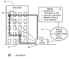
- FIG. 1 is a block diagram of a GPS-based radio locator system 10 in accordance with a preferred embodiment of the present invention.
- the locator system 10 comprises a plurality of radios 20 , a gateway 40 , an external network 16 , and a computer management system 14 .
- the radios 20 and the gateway 40 each comprises, for example, a communication node in one or more ad hoc wireless networks, some of which are described further hereinbelow.
- the radios 20 and the gateway 40 may sometimes be referred to herein as “wireless communication devices.”
- each radio 20 and the gateway 40 preferably includes a GPS receiver therewith.
- Each such radio 20 is generally referred to herein as a “GPS radio,” and the gateway 40 is generally referred to herein as a “GPS gateway.”
- the computer management system 14 primarily includes a server, and although different computer management system arrangements may be utilized, all arrangements will generally be referred to hereinafter as a “server.”
- the server 14 may be physically co-located with the gateway 40 , thereby foregoing the need for an external network connecting a gateway to a server.
- the co-location of a gateway 40 with a server 14 is sometimes referred to as a “gateway controller” and is illustrated, for example, in the detection system 110 of FIG. 2 .
- Global Positioning System or “GPS”
- GLONASS Russian system
- Galileo European Space Agency
- a GPS radio 20 is diagrammatically shown to include: a GPS receiver 24 for calculating the position of the GPS radio 20 and, thus, the position of the individual or asset carrying the GPS radio 20 ; a standards based radio 26 for two-way wireless communications with, for example, one or more other GPS radios 20 and/or a GPS gateway 40 ; and an electrical power source 28 , such as a battery.
- the GPS radio 20 further includes radio frequency ranging capability in order to determine the distance between it and another wireless communication device 20 , 40 .
- the GPS receiver 24 is incorporated directly into the GPS radio 20 and, as such, a separate interface between the respective components is not illustrated.
- a GPS receiver 24 may be physically separated from, but disposed in electronic communication with, the other portions of a GPS radio 20 , thereby providing generally similar functionality to the arrangement depicted in FIGS. 1 and 2 .
- Such an arrangement is shown, for example, in the detection system 210 of FIG. 4 .
- the GPS receiver 24 and the other portions of the GPS radio 20 may be contained in separate housings, and electronic communication between the GPS receiver 24 and the other portions of the GPS radio 20 may be effected wirelessly or by way of cabled connections.
- the GPS radio 20 may further include a sensor interface 30 for acquiring data from one or more sensors associated with the GPS radio 20 .
- a GPS radio 20 may sometimes be referred to as a “GPS-RSI” radio, or a “GPS-RSI.”
- GPS-RSI GPS-RSI radio
- the GPS-RSI radio 20 preferably is configured to interface with sensors that, for example, monitor the assets, environmental characteristics of the assets, and/or geographical locations of the assets.
- such sensors may actually be included as components integral with the GPS-RSI radio 20 ; in other embodiments, such sensors may be external to the GPS-RSI radio 20 but nevertheless disposed in electronic communication with the sensor interface for data exchange therebetween.
- Electronic communication between the sensor interface and a sensor is exchanged wirelessly in some embodiments and by way of cabled connections in other embodiments.
- the sensor interface comprises a multi-conductor connector, such as a ribbon cable, that passes from the interior of a GPS-RSI radio 20 to an external sensor, sensor array, or docking station that receives the GPS-RSI radio 20 .
- Exemplary sensors include, but are not limited to, electronic seals, magnetic seals, cameras, microphones, temperature sensors, humidity sensors, radiation sensors, and motion sensors.
- the GPS radio 20 also may include a “Wake-Up Receiver” 22 for receiving wireless signals.
- a “Wake-Up Receiver” 22 for receiving wireless signals.
- the Wake-Up Receiver 22 which has a relatively low power consumption rate compared to that of the standards based radio 26 , generally remains active for detecting incoming wireless wake-up signals.
- the Wake-Up Receiver 22 Upon receipt of a wake-up signal intended for the GPS radio 20 , the Wake-Up Receiver 22 generally wakes-up the standards based radio 26 for receiving and transmitting data via the standards based radio 26 .
- Those components of the GPS radio 20 that consume relatively high amounts of power thereby are generally active only when needed.
- Such a Wake-up Receiver 22 generally includes components for receiving wireless wake-up signals.
- the Wake-Up Receiver 22 may be generally similar in function to the “WT Component” described in detail, for example, in incorporated International Patent Application Publication No. WO 03/098851 A1 (and which international application entered the U.S. national phase and published as U.S. Patent Application Publication No. US 2005/0215280, also incorporated herein by reference).
- the Wake-Up Receiver 22 moreover has been occasionally referred to as a “tag turn-on circuit,” a “TTOC” or a “Wake-Up Rx.”
- the process for determining whether to wake-up the standards based radio of the GPS radio 20 furthermore may include a number of steps that are performed in a particular sequence, especially if the GPS radio 20 is disposed in a noisy radio-frequency (RF) environment.
- RF radio-frequency
- a GPS gateway 40 may include: a GPS receiver 24 for calculating the position of the GPS gateway 40 ; a standards based radio 26 for two-way wireless communications with one or more GPS radios 20 and/or one or more other gateways; and an electrical power source 48 , such as a battery.
- the GPS gateway 40 further includes radio frequency ranging capability in order to determine the distance between it and another wireless communication device 20 , 40 .
- the GPS gateway 40 may also include a sensor interface 30 for acquiring data from one or more sensors associated with the GPS gateway 40 .
- the GPS gateway 40 may further include a “Wake-Up Transmitter” 42 for transmitting wireless wake-up signals.
- the Wake-Up Transmitter 42 has occasionally been referred to as a “tag turn-on,” a “TTO” or a “Wake-Up Tx,” and the Wake-Up Transmitter 42 is configured to send signals to Wake-Up Receivers 22 , TTOCs, or the like, for wake-up of GPS radios 20 .
- a GPS gateway may include a Wake-Up Receiver 22 like those included in the GPS radios 20 , either in place of or in addition to the Wake-Up Transmitter.
- the Wake-Up Transmitter is further configured to send signals to GPS gateways.
- the GPS radios 20 are programmed to communicate directly with the GPS gateway 40 or to communicate via hopping. Furthermore, fewer GPS gateways are needed to cover an area when the GPS radios 20 communicate via hopping to reach a GPS gateway 40 .
- the GPS gateway 40 facilitates communication between one or more wireless networks, formed by the GPS radios 20 , and the external network 16 . As such, the GPS gateway 40 further includes one or more appropriate connections for communicating with such an external network 16 , such connections including but not limited to network interfaces for mobile phone, WiFi, two-way radio, secure radio links, Ethernet, and/or satellite communications. Each GPS gateway 40 thus serves as an access point or gateway for communications with the external network 16 . Electronic communication between the network interface and the external network 16 may be exchanged wirelessly or by way of cabled connections.
- the external network 16 may include wired or wireless communications using any of the foregoing technologies or combination thereof, as well as any other appropriate communication technologies. Additionally, the external network 16 may incorporate use of the Internet or some other wide area network (WAN).
- WAN wide area network
- FIGS. 6-11 are schematic diagrams of locator systems in accordance with one or more preferred operational modes of a system of the present invention.
- FIG. 6 illustrates a first operational mode in which a system 10 is used to locate a GPS radio 20 in a multistory building 50 .
- the detection system 10 generally comprises a plurality of GPS radios 20 and a GPS gateway 40 .
- each GPS radio 20 includes a standards based radio 26 and a GPS receiver 24 .
- the GPS radios 20 and the GPS gateway 40 are the communication nodes of an ad hoc wireless network.
- the GPS gateway 40 is in direct communication with a first GPS radio 20
- the first GPS radio 20 is in direct communication with a second GPS radio 20 .
- the GPS gateway 40 communicates with the second GPS radio 20 only by hopping.
- the GPS radios 20 are carried into or otherwise located in an environment such as a building 50 , while the GPS gateway 40 is stationed adjacent the building 50 .
- the GPS gateway 40 is preferably positioned in a location with reliable GPS access and with reasonable access to other communication systems located external to the building. No particular location is generally required or preferred for the GPS radios 20 , because each must typically move with the firefighter, police officer, serviceperson or the like that is carrying it.
- each wireless communication device 20 , 40 may be described or characterized via a coordinate system.
- each device 20 , 40 may be described using a conventional Cartesian coordinate system having three mutually perpendicular axes such as an X axis, Y axis, and Z axis.
- a location of an object may be identified by a (x,y,z) position.
- such a coordinate system may be approximated, at least locally, using conventional latitude, longitude and elevation (or “z”) coordinates.
- z latitude, longitude and elevation
- the coordinates of the GPS gateway 40 as illustrated are (x 1 ,y 1 ,z 1 ), the coordinates of the first GPS radio 20 are (x 2 ,y 2 ,z 2 ), and the coordinates of the second GPS radio 20 are (x 3 ,y 3 ,z 3 ).
- the GPS receiver 24 on each respective GPS radio 20 and GPS gateway 40 calculates, on a continuous or periodic basis, its position according to conventional means, i.e., standard GPS techniques.
- conventional means i.e., standard GPS techniques.
- a GPS receiver 24 of the GPS radios 20 may be configured to calculate the azimuth or z-axis coordinate
- the GPS receivers 24 of the GPS radios 20 generally are unable to accurately determine the azimuth or z-axis coordinate because of the inability to “see” a sufficient number of GPS satellites. This problem is exacerbated by the building 50 in which the GPS radios 20 are carried. Accordingly, such calculation of the azimuth or z-axis is generally ignored.
- the position of a GPS radio 20 on a horizontal plane (i.e., “X-Y” plane), however, can generally be calculated accurately. Nonetheless, the determination of a GPS radio's absolute or relative position on the z-axis is critical in some applications. For example, a firefighter may lose his way or become incapacitated as he moves in the building 50 , and it may be necessary to find, guide or rescue the firefighters In such a situation, information about the firefighter's vertical position may become critical in order to determine, for example, the floor of the building on which the firefighter is located.
- information about the firefighter's vertical location may be determined as follows.
- the (x,y) coordinates are determined for the firefighter's GPS radio 20 and for the GPS gateway 40 . As illustrated, these coordinates are (x 1 ,y 1 ) for the GPS gateway 40 and (x 2 ,y 2 ) for the first GPS radio 20 . Preferably, each respective device determines its (x,y) coordinates using the respective GPS receivers of the devices. Furthermore, it is assumed in this example that the firefighter is carrying the first GPS radio 20 .
- FIG. 7 is a schematic diagram illustrating a portion of the location process.
- the distance A within a horizontal plane between the two devices 20 , 40 may be calculated as the hypotenuse of a right triangle using the Pythagorean theorem, wherein the lengths of the two other sides of the triangle are determined using the (x,y) GPS coordinates calculated by the respective GPS receivers 24 .
- radio frequency ranging of the two wireless communication device 20 , 40 may be used to determine the absolute distance therebetween, which is denoted R.
- each GPS radio 20 and each GPS gateway 40 includes radio frequency ranging capability for determining the distance between it and another for purposes made clear below.
- Such ranging capability may be provided using the Wake-Up Receivers 22 /Wake-Up Transmitters 42 and/or the standards based radios 26 on respective wireless communication devices 20 , 40 .
- Ranging may be accomplished using lasers, infrared, sound, and the like.
- Various conventional ranging techniques are available including RF power level measurements or time of arrival techniques. Typically, a time of arrival method is more accurate but other methods can be used.
- the elevational differential between the GPS gateway 40 and the first GPS radio 20 may be determined as shown in FIG. 8 , which is a schematic diagram illustrating another portion of the location process.
- the absolute distance R is the length of the hypotenuse of a second right triangle, wherein the length one of the other sides is the distance A in the horizontal plane and the length of the other side represents the elevational differential E between the GPS gateway 40 and the first GPS radio 20 .
- the Pythagorean theorem may thus be used once again, this time to calculate the elevational differential E between the two devices 20 , 40 .
- one additional step may be necessary at this point. More particularly, it may be necessary or desirable to determine whether the elevational differential is in the upward or downward direction. This may be done, for example, using the GPS azimuth, which although too inaccurate to be used reliably to determine the magnitude of the differential, is reliable enough to determine whether the differential is in the positive or negative direction. Other sensors can be used for such purposes, such as antenna arrays or direction antennas to determine angle of arrival.
- (x,y) positions of the two wireless communication devices 20 , 40 are calculated using GPS.
- the horizontal distance A then can be calculated.
- Other methods can be used to more accurately calculate the elevation, which may include certain corrective fine tuning, but the aforementioned approach is the simplest and preferred method.
- FIG. 9A illustrates a second operational mode in which a system 10 is once again used to locate a GPS radio 20 in a building 50 .
- the detection system 10 comprises a plurality of GPS radios 20 and a gateway controller 40 .
- the gateway controller 40 may or may not be a GPS gateway in this operational mode.
- the GPS radios 20 and the gateway controller 40 are the communication nodes of an ad hoc wireless network.
- the gateway controller 40 is in direct communication with the first GPS radio 20
- the first GPS radio 20 is in direct communication with the second GPS radio 20 .
- the gateway controller 40 communicates with the second GPS radio 20 only by hopping.
- the operational mode of FIG. 9A is similar to that of FIGS. 6-8 except that the elevational differential being determined is the one between the first GPS radio 20 and the second GPS radio 20 , i.e., (z 3 ⁇ z 2 ), and thus the wireless communication devices 20 , 40 for which the elevational differential is determined are both GPS radios 20 .
- the methodology generally is the same, with the horizontal distance A being determined using the (x,y) coordinates calculated by the GPS receivers 24 of the two GPS radios 24 , with ranging being used to determine the absolute distance R between the two GPS radios 20 , and with the Pythagorean theorem being applied twice to determine the elevation E representing the elevational differential between the two GPS radios 20 , i.e., (z 3 ⁇ z 2 ).
- a gateway 40 may or may not be present in order for the first GPS radio 20 to be utilized to determine the elevational differential between it and the second GPS radio 20 .
- FIG. 9B This is illustrated in FIG. 9B , wherein the two GPS radios 20 are serving as the communication nodes of an ad hoc wireless network but where no GPS gateway/gateway controller 40 is being used.
- the methodology used to accomplish the determination of elevational differential in FIG. 9A is thus identical to the methodology that is used in the system and operational mode shown in FIG. 9B .
- Network aiding a GPS receiver 24 is somewhat vendor-specific, but in general it is accomplished by providing Almanac, Ephemeris, GPS time, approximate location and other pertinent information to a GPS receiver 24 to increase the sensitivity and/or accuracy of the GPS receiver 24 .
- the methods of the present invention may be further employed as a preliminary step in determining the elevation of a wireless communication device, such as a GPS radio 20 , relative to a more fixed elevation, such as the ground outside a building or elevation above sea level.
- a wireless communication device such as a GPS radio 20
- a more fixed elevation such as the ground outside a building or elevation above sea level.
- the relative elevational differential of the second wireless communication device such as one of the GPS radios 20 inside the building 50 , may be calculated by adding the relative elevational differential between the two wireless communication devices to the height of the GPS gateway 40 above the ground.
- the GPS gateway 40 is mounted on a fire truck six feet off the ground, the six feet may be added to the relative elevational differential determined by the methods described herein in order to determine the actual elevation, relative to the ground, of the a GPS radio 20 located somewhere inside the building 50 .
- the elevation above sea level of the second wireless communication device may be calculated by adding the relative elevational differential between the two wireless communication devices to the elevation above sea level of the GPS gateway 40 .
- FIG. 10 illustrates a third operational mode in which a system 10 is once again used to locate a GPS radio 20 in a building 50 .
- the detection system 10 once again comprises a plurality of GPS radios 20 , a GPS gateway 40 , an external network 16 , and a server 14 .
- the GPS radios 20 and the GPS gateway 40 again comprise communication nodes of an ad hoc wireless network.
- the situation illustrated in FIG. 10 is similar to that of FIG. 6 , wherein the GPS gateway 40 is in direct communication with the first GPS radio 20 , and the first GPS radio 20 is in direct communication with the second GPS radio 20 , but the GPS gateway 40 communicates with the second GPS radio 20 only by hopping. Further, in this illustration, the gateway 40 is not co-located with the server 14 .
- the server 14 may provide a variety of assistance to the other components of the locator system 10 .
- the server 14 may provide network aiding, helping the GPS receivers 24 determine their respective (x,y) position.
- the server 14 may also help provide more accurate calculation of elevational information.
- the server 14 may provide mapping software that may be used to track and locate GPS radios 20 within the building 50 or in other environments. Still further, the server 14 may provide voice translation.
- FIG. 11 illustrates a fourth operational mode in which a system 10 is once again used to locate a GPS radio 20 in a building 50 .
- the detection system 10 once again comprises a plurality of GPS radios 20 , a GPS gateway 40 , an external network (not shown), and a server (not shown).
- the GPS radios 20 and the GPS gateway 40 again comprise communication nodes of an ad hoc wireless network.
- the situation illustrated in FIG. 11 is similar to that of FIGS. 6 and 10 , wherein the GPS gateway 40 is in direct communication with the first GPS radio 20 , and the first GPS radio 20 is in direct communication with the second GPS radio 20 , but the GPS gateway 40 communicates with the second GPS radio 20 only by hopping.
- the gateway 40 is integrated with the server 14 .
- the server 14 may merely be located with the gateway 40 but not integrated directly therein.
- FIG. 12 illustrates a fifth operational mode in which a locator system 10 is used to locate a GPS radio 20 in a building 50 .
- the detection system 10 once again comprises a plurality of GPS radios 20 , a GPS gateway 40 , an external network 16 , and a server 14 .
- the GPS radios 20 and the GPS gateway 40 again comprise communication nodes of an ad hoc wireless network.
- the situation illustrated in FIG. 12 is similar to that of FIGS. 6 , 10 and 11 , wherein the GPS gateway 40 is in direct communication with the first GPS radio 20 , and the first GPS radio 20 is in direct communication with the second GPS radio 20 , but the GPS gateway 40 communicates with the second GPS radio 20 only by hopping. Further, in this illustration, as with that of FIG. 10 , the gateway 40 is not co-located with the server 14 .
- the methodology described previously is used as follows.
- the (x,y) positions of the two GPS radios 20 and the GPS gateway 40 are determined using respective GPS receivers 24 . Ranging is used to determine the distance between the GPS gateway 40 and the first GPS radio 20 and the distance between the first GPS radio 20 and the second GPS radio 20 .
- a first relative elevational differential can then be determined between the GPS gateway 40 and the first GPS radio 20
- a second relative elevational differential can be determined between the first GPS radio 20 and the second GPS radio 20 .
- the relative elevational differential between the GPS gateway 40 and the second GPS radio 20 can then be determined by combining the first and second relative elevational differentials found in the preceding step.
- FIG. 13 illustrates a sixth operational mode in which a locator system 10 is used to locate a GPS radio 20 in a building 50 .
- the detection system 10 once again comprises a plurality of GPS radios 20 , a GPS gateway 40 , an external network 16 , and a server 14 .
- the GPS radios 20 and the GPS gateway 40 again comprise communication nodes of an ad hoc wireless network.
- the GPS gateway 40 and the two GPS radios 20 are all in direct communication with one another. Further, in this illustration, as with that of FIG. 10 , the gateway 40 is not co-located with the server 14 .
- the methodology described with regard to FIG. 12 may be used to determine, indirectly, the relative elevational differential between the GPS gateway 40 and the second GPS radio 20 .
- the methodology described with respect to FIG. 6 may be applied to determine the relative elevational differential between the GPS gateway 40 and the second GPS radio 20 directly. The two methods may then be compared and combined, as appropriate, to determine a potentially more accurate calculation of the actual relative elevational differential. In this regard, such comparison and combination may be carried out with or without assistance from the server 14 .
- power consumption may be reduced through use of wake-up technology. Reduction in unnecessary power consumption may also be achieved by utilizing common designation ad hoc networks such as, for example, class-based networks.
- Common designation networking is disclosed, for example, in U.S. patent application Ser. No. 11/161,539, which published as U.S. Patent Application Publication No. 2006/0023678 A1, each of which is hereby incorporated herein by reference.
- Class based networking can be used to help aid other radios that need location. The operation would be to send out a signal to communicate with radios that have acquired a GPS position. If a radio has acquired the position, a class called GPSPositionAvailable could be added to the list of valid classes the radio responds to and setup a communication.
- the network aiding information can be transferred to the original radio so that the (x,y) coordinates can be calculated. Once that has been achieved, the range between the radios can be determined and the elevation calculated.
- the reverse could also be setup by setting up a class of radios that need network aid such as GPSPositionUnavailable and having a radio that has already acquired the position to pass it along once it is ready.
- the systems and methodologies described and illustrated herein may be used to track and/or position any asset to which a GPS radio 20 may be attached, carried or the like. More particularly, the systems and methodologies described and illustrated herein make it possible to accurately calculate the relative position of GPS radios 20 in buildings 50 or other urban environments, as well as in mountainous locations, in all three directions, i.e., along the X, Y and Z axes. In this regard, it is possible to calculate the position of a GPS radio 20 relative to the ground directly, indirectly via hopping radios, or both. Significantly, many of the methodologies described herein can be carried out using only two wireless communication devices 20 , 40 , rather than requiring three, four or more for conventional triangulation.
Abstract
Description
Claims (19)
Priority Applications (7)
| Application Number | Priority Date | Filing Date | Title |
|---|---|---|---|
| US11/555,173 US7742773B2 (en) | 2005-10-31 | 2006-10-31 | Using GPS and ranging to determine relative elevation of an asset |
| US12/168,195 US20080304443A1 (en) | 2000-12-22 | 2008-07-07 | Standards based communictions for a container security system |
| US12/202,247 US20090016308A1 (en) | 2000-12-22 | 2008-08-30 | Antenna in cargo container monitoring and security system |
| US12/473,264 US8218514B2 (en) | 2000-12-22 | 2009-05-27 | Wireless data communications network system for tracking containers |
| US12/556,538 US8280345B2 (en) | 2000-12-22 | 2009-09-09 | LPRF device wake up using wireless tag |
| US12/774,589 US20100214060A1 (en) | 2000-12-22 | 2010-05-05 | Wireless data communications network system for tracking containers |
| US12/780,823 US8078139B2 (en) | 2000-12-22 | 2010-05-14 | Wireless data communications network system for tracking container |
Applications Claiming Priority (2)
| Application Number | Priority Date | Filing Date | Title |
|---|---|---|---|
| US59693005P | 2005-10-31 | 2005-10-31 | |
| US11/555,173 US7742773B2 (en) | 2005-10-31 | 2006-10-31 | Using GPS and ranging to determine relative elevation of an asset |
Related Parent Applications (1)
| Application Number | Title | Priority Date | Filing Date |
|---|---|---|---|
| US11/618,931 Continuation-In-Part US7907941B2 (en) | 2000-12-22 | 2007-01-01 | Determining presence of radio frequency communication device |
Related Child Applications (2)
| Application Number | Title | Priority Date | Filing Date |
|---|---|---|---|
| US11/555,164 Continuation-In-Part US7742772B2 (en) | 2000-12-22 | 2006-10-31 | Determining relative elevation using GPS and ranging |
| US12/140,253 Continuation-In-Part US20080303897A1 (en) | 2000-12-22 | 2008-06-16 | Visually capturing and monitoring contents and events of cargo container |
Publications (2)
| Publication Number | Publication Date |
|---|---|
| US20070099629A1 US20070099629A1 (en) | 2007-05-03 |
| US7742773B2 true US7742773B2 (en) | 2010-06-22 |
Family
ID=38123228
Family Applications (2)
| Application Number | Title | Priority Date | Filing Date |
|---|---|---|---|
| US11/555,164 Active 2028-07-06 US7742772B2 (en) | 2000-12-22 | 2006-10-31 | Determining relative elevation using GPS and ranging |
| US11/555,173 Active 2028-07-11 US7742773B2 (en) | 2000-12-22 | 2006-10-31 | Using GPS and ranging to determine relative elevation of an asset |
Family Applications Before (1)
| Application Number | Title | Priority Date | Filing Date |
|---|---|---|---|
| US11/555,164 Active 2028-07-06 US7742772B2 (en) | 2000-12-22 | 2006-10-31 | Determining relative elevation using GPS and ranging |
Country Status (2)
| Country | Link |
|---|---|
| US (2) | US7742772B2 (en) |
| WO (1) | WO2007067831A1 (en) |
Cited By (7)
| Publication number | Priority date | Publication date | Assignee | Title |
|---|---|---|---|---|
| US20100250134A1 (en) * | 2009-03-24 | 2010-09-30 | Qualcomm Incorporated | Dead reckoning elevation component adjustment |
| US20150070218A1 (en) * | 2013-09-06 | 2015-03-12 | Tag-Comm Inc. | Method and system for locating wireless devices within a local region |
| US9571986B2 (en) | 2014-05-07 | 2017-02-14 | Johnson Controls Technology Company | Systems and methods for detecting and using equipment location in a building management system |
| US9709672B2 (en) | 2013-08-16 | 2017-07-18 | Drnc Holdings, Inc. | Method and system for identifying and finding a range of an object |
| US10079704B2 (en) | 2014-09-22 | 2018-09-18 | Drnc Holdings, Inc. | Transmission apparatus for a wireless device using delta-sigma modulation |
| US10481574B2 (en) | 2016-05-04 | 2019-11-19 | Johnson Controls Technology Company | Building alarm management system with mobile device notifications |
| US10982868B2 (en) | 2015-05-04 | 2021-04-20 | Johnson Controls Technology Company | HVAC equipment having locating systems and methods |
Families Citing this family (14)
| Publication number | Priority date | Publication date | Assignee | Title |
|---|---|---|---|---|
| US7583769B2 (en) | 2005-06-16 | 2009-09-01 | Terahop Netowrks, Inc. | Operating GPS receivers in GPS-adverse environment |
| US7742772B2 (en) | 2005-10-31 | 2010-06-22 | Terahop Networks, Inc. | Determining relative elevation using GPS and ranging |
| US8144671B2 (en) | 2005-07-01 | 2012-03-27 | Twitchell Jr Robert W | Communicating via nondeterministic and deterministic network routing |
| US7783246B2 (en) | 2005-06-16 | 2010-08-24 | Terahop Networks, Inc. | Tactical GPS denial and denial detection system |
| US7142107B2 (en) | 2004-05-27 | 2006-11-28 | Lawrence Kates | Wireless sensor unit |
| WO2009140669A2 (en) | 2008-05-16 | 2009-11-19 | Terahop Networks, Inc. | Securing, monitoring and tracking shipping containers |
| US8391435B2 (en) | 2008-12-25 | 2013-03-05 | Google Inc. | Receiver state estimation in a duty cycled radio |
| US20110082812A1 (en) * | 2009-10-01 | 2011-04-07 | Abdul Hamid Salemizadeh | Package transport monitoring and analysis |
| US8665340B2 (en) * | 2010-04-29 | 2014-03-04 | Intellectual Ventures Fund 83 Llc | Indoor/outdoor scene detection using GPS |
| US8532676B1 (en) * | 2012-05-22 | 2013-09-10 | Polaris Wireless, Inc. | Estimating whether a wireless terminal is indoors versus outdoors using probabilities and classifications |
| AU2012227260B9 (en) * | 2012-09-21 | 2014-05-29 | Safemine Ag | Method and device for generating proximity warnings |
| US10794939B2 (en) * | 2013-05-21 | 2020-10-06 | The Research Foundation For The State University Of New York | Sensors for power distribution network and electrical grid monitoring system associated therewith |
| US9052999B1 (en) * | 2013-09-11 | 2015-06-09 | Sprint Spectrum L.P. | Method and system for transmitting a determined altitude of a user equipment device located in a building |
| CN108011700B (en) | 2016-10-31 | 2021-04-09 | 华为技术有限公司 | Indication information sending method, receiving method and equipment |
Citations (203)
| Publication number | Priority date | Publication date | Assignee | Title |
|---|---|---|---|---|
| US3805265A (en) | 1971-10-06 | 1974-04-16 | Rcds Enterprises Inc | Radiant wave locating system |
| US4165024A (en) | 1977-09-09 | 1979-08-21 | Cato Oil And Grease Co. | Bulk shipping container |
| US4613990A (en) | 1984-06-25 | 1986-09-23 | At&T Bell Laboratories | Radiotelephone transmission power control |
| US4680583A (en) | 1985-01-30 | 1987-07-14 | Northern Telecom Limited | Terminal address assignment in a broadcast transmission system |
| US4688244A (en) | 1986-11-10 | 1987-08-18 | Marwan Hannon | Integrated cargo security system |
| US4750197A (en) | 1986-11-10 | 1988-06-07 | Denekamp Mark L | Integrated cargo security system |
| US4817537A (en) | 1987-03-16 | 1989-04-04 | Cripe Alan R | Container carrying convertible rail-highway vehicle |
| US5040238A (en) | 1990-06-29 | 1991-08-13 | Motorola, Inc. | Trunking system communication resource reuse method |
| US5054052A (en) | 1989-04-03 | 1991-10-01 | Mitsubishi Denki Kabushiki Kaisha | Mobile telephone device with low power consumption |
| EP0467036A2 (en) | 1990-06-15 | 1992-01-22 | Savi Technology, Inc. | Method and apparatus for radio identification and tracking |
| US5117501A (en) | 1988-08-08 | 1992-05-26 | General Electric Company | Dynamic regrouping in a trunked radio communications system |
| US5129096A (en) | 1989-05-12 | 1992-07-07 | Tunstall Telecom Limited | System which routes radio transmissions to selected repeaters for retransmission |
| US5210540A (en) | 1991-06-18 | 1993-05-11 | Pioneer Electronic Corporation | Global positioning system |
| US5265025A (en) | 1990-07-11 | 1993-11-23 | Mitsubishi Denki Kabushiki Kaisha | Navigation system using satellite signals |
| US5295154A (en) | 1991-10-01 | 1994-03-15 | Norand Corporation | Radio frequency local area network |
| US5331637A (en) | 1993-07-30 | 1994-07-19 | Bell Communications Research, Inc. | Multicast routing using core based trees |
| US5369784A (en) | 1991-08-01 | 1994-11-29 | City Communications Limited | Radio communications system using multiple simultaneously transmitting transceivers |
| US5400254A (en) | 1992-06-19 | 1995-03-21 | Sharp Kabushiki Kaisha | Trace display apparatus for a navigation system |
| US5425051A (en) | 1992-11-09 | 1995-06-13 | Norand Corporation | Radio frequency communication network having adaptive parameters |
| US5442758A (en) | 1993-07-19 | 1995-08-15 | Sequent Computer Systems, Inc. | Apparatus and method for achieving reduced overhead mutual exclusion and maintaining coherency in a multiprocessor system utilizing execution history and thread monitoring |
| US5511232A (en) | 1994-12-02 | 1996-04-23 | Motorola, Inc. | Method for providing autonomous radio talk group configuration |
| US5565858A (en) | 1994-09-14 | 1996-10-15 | Northrop Grumman Corporation | Electronic inventory system for stacked containers |
| US5579306A (en) | 1994-09-01 | 1996-11-26 | Ericsson Inc. | Time and frequency slot allocation system and method |
| US5590409A (en) | 1994-05-12 | 1996-12-31 | Ntt Mobile Communications Network Inc. | Transmission power control method and a transmission power control apparatus |
| US5596652A (en) | 1995-03-23 | 1997-01-21 | Portable Data Technologies, Inc. | System and method for accounting for personnel at a site and system and method for providing personnel with information about an emergency site |
| US5604892A (en) | 1992-09-01 | 1997-02-18 | Nuttall; David J. H. | Method for modeling a physical system of elements using a relational database |
| US5606313A (en) | 1993-12-10 | 1997-02-25 | Motorola, Inc. | Low power addressable data communication device and method |
| US5640151A (en) | 1990-06-15 | 1997-06-17 | Texas Instruments Incorporated | Communication system for communicating with tags |
| GB2308947A (en) | 1996-01-04 | 1997-07-09 | I D Systems Ltd | Identification tag with environmental sensing facility |
| US5652751A (en) | 1996-03-26 | 1997-07-29 | Hazeltine Corporation | Architecture for mobile radio networks with dynamically changing topology using virtual subnets |
| US5682379A (en) | 1993-12-23 | 1997-10-28 | Norand Corporation | Wireless personal local area network |
| US5732077A (en) | 1995-11-13 | 1998-03-24 | Lucent Technologies Inc. | Resource allocation system for wireless networks |
| US5761195A (en) | 1995-05-04 | 1998-06-02 | Interwave Communications International, Ltd. | Methods and apparatus for connecting calls in a hierarchical cellular network |
| US5790946A (en) | 1993-07-15 | 1998-08-04 | Rotzoll; Robert R. | Wake up device for a communications system |
| US5793882A (en) | 1995-03-23 | 1998-08-11 | Portable Data Technologies, Inc. | System and method for accounting for personnel at a site and system and method for providing personnel with information about an emergency site |
| US5833910A (en) | 1995-10-03 | 1998-11-10 | Mecanismos Auxiliares Industiales S.A. | Mold and method for manufacturing conduit grommet elements |
| US5862803A (en) | 1993-09-04 | 1999-01-26 | Besson; Marcus | Wireless medical diagnosis and monitoring equipment |
| US5890054A (en) | 1996-11-14 | 1999-03-30 | Telxon Corporation | Emergency mobile routing protocol |
| US5892441A (en) | 1996-06-26 | 1999-04-06 | Par Government Systems Corporation | Sensing with active electronic tags |
| US5907491A (en) | 1996-08-23 | 1999-05-25 | Csi Technology, Inc. | Wireless machine monitoring and communication system |
| US5917423A (en) | 1995-04-12 | 1999-06-29 | Lojack Corporation | Vehicles tracking transponder system and transponding method |
| US5939982A (en) | 1997-06-09 | 1999-08-17 | Auratek Security Inc. | Apparatus for monitoring opening of sealed containers |
| US5943610A (en) | 1996-04-05 | 1999-08-24 | Nec Corporation | Transmission power control with dynamic step values |
| US5950124A (en) | 1995-09-06 | 1999-09-07 | Telxon Corporation | Cellular communication system with dynamically modified data transmission parameters |
| US5951613A (en) | 1996-10-23 | 1999-09-14 | Caterpillar Inc. | Apparatus and method for determining the position of a work implement |
| US5974236A (en) | 1992-03-25 | 1999-10-26 | Aes Corporation | Dynamically reconfigurable communications network and method |
| US5977913A (en) | 1997-02-07 | 1999-11-02 | Dominion Wireless | Method and apparatus for tracking and locating personnel |
| US6005884A (en) | 1995-11-06 | 1999-12-21 | Ems Technologies, Inc. | Distributed architecture for a wireless data communications system |
| US6006100A (en) | 1990-05-25 | 1999-12-21 | Norand Corporation | Multi-level, hierarchical radio-frequency communication system |
| US6072784A (en) | 1997-07-25 | 2000-06-06 | At&T Corp. | CDMA mobile station wireless transmission power management with adaptive scheduling priorities based on battery power level |
| US6078789A (en) | 1996-05-01 | 2000-06-20 | Bodenmann; Olivier | Wireless peripheral interface |
| US6091724A (en) | 1997-11-20 | 2000-07-18 | International Business Machines Corporation | Routing messages within a network using the data content of the message |
| US6097707A (en) | 1995-05-19 | 2000-08-01 | Hodzic; Migdat I. | Adaptive digital wireless communications network apparatus and process |
| US6104512A (en) | 1998-01-23 | 2000-08-15 | Motorola, Inc. | Method for adjusting the power level of an infrared signal |
| US6118988A (en) | 1998-03-02 | 2000-09-12 | Hyundai Electronics Industries Co., Ltd. | Transmission power control system and method for a mobile station |
| US6125306A (en) | 1995-10-13 | 2000-09-26 | Matsushita Electric Industrial Co., Ltd. | System for controlling physical distribution pallets |
| US6127928A (en) | 1998-02-10 | 2000-10-03 | E-Tag Systems, Inc. | Method and apparatus for locating and tracking documents and other objects |
| US6127976A (en) | 1998-09-03 | 2000-10-03 | Wherenet, Inc. | Distributed network for multi-lateration with circularly polarized antenna for hemispherical coverage |
| US6134587A (en) | 1996-12-27 | 2000-10-17 | Nec Corporation | Method of setting up ad hoc local area network, method of communicating using said network, and terminal for use with said network |
| US6192400B1 (en) | 1990-05-25 | 2001-02-20 | Intermec Ip Corp. | Multilevel data communication system including local and host systems |
| US6198913B1 (en) | 1997-08-31 | 2001-03-06 | Samsung Electronics Co., Ltd. | Automatic wake-up device for radio automatic recognition terminal and communication method using the terminal |
| US6201974B1 (en) | 1996-09-06 | 2001-03-13 | Nokia Mobile Phones Limited | Mobile station and network having hierarchical index for cell broadcast service |
| US20010000019A1 (en) | 1997-07-24 | 2001-03-15 | Bowers John H. | Inventory system using articles with RFID tags |
| US6256303B1 (en) | 1999-10-15 | 2001-07-03 | Akoo, Inc. | Wireless broadcast link to remote receiver |
| US6313745B1 (en) | 2000-01-06 | 2001-11-06 | Fujitsu Limited | System and method for fitting room merchandise item recognition using wireless tag |
| US20010050550A1 (en) | 2000-02-29 | 2001-12-13 | Norio Yoshida | High frequency component, communication apparatus, and method for measuring characteristics of high frequency component |
| US6354493B1 (en) | 1999-12-23 | 2002-03-12 | Sensormatic Electronics Corporation | System and method for finding a specific RFID tagged article located in a plurality of RFID tagged articles |
| US6360169B1 (en) | 2000-09-07 | 2002-03-19 | Umesh Dudabey | System for determining and tracking changes in location |
| US20020039896A1 (en) | 2000-10-04 | 2002-04-04 | Brown Barry Allen Thomas | Method and apparatus for disabling mobile telephones |
| US6381467B1 (en) | 2000-06-22 | 2002-04-30 | Motorola, Inc. | Method and apparatus for managing an ad hoc wireless network |
| US20020050932A1 (en) | 2000-10-30 | 2002-05-02 | Ocean Systems Engineering Corporation | Environment and hazard condition monitoring system |
| US6405102B1 (en) | 1996-06-21 | 2002-06-11 | Symbol Technologies, Inc. | RF-interrogatable processing system |
| US6404082B1 (en) | 1999-09-24 | 2002-06-11 | Siemens Westinghouse Power Corporation | Exciter having thermally isolated diode wheel and method of removing diode wheel for same |
| US6409082B1 (en) | 1997-07-25 | 2002-06-25 | Perseu Administration (Proprietary) Limited | Tracking of products |
| US6418299B1 (en) | 1996-01-11 | 2002-07-09 | Bbn Corporation | Self-organizing mobile wireless station network |
| US20020089434A1 (en) | 2000-11-06 | 2002-07-11 | Ohanes Ghazarian | Electronic vehicle product and personnel monitoring |
| US6424264B1 (en) | 2000-10-12 | 2002-07-23 | Safetzone Technologies Corporation | System for real-time location of people in a fixed environment |
| US6424260B2 (en) | 1998-09-11 | 2002-07-23 | Key-Trak, Inc. | Mobile object tracking system |
| US20020098861A1 (en) | 2001-01-19 | 2002-07-25 | International Business Machines Corporation | Method and system for preventing wireless devices from interfering with other equipment in a sensitive area |
| US6427913B1 (en) | 1998-09-11 | 2002-08-06 | Key-Trak, Inc. | Object control and tracking system with zonal transition detection |
| US6437692B1 (en) | 1998-06-22 | 2002-08-20 | Statsignal Systems, Inc. | System and method for monitoring and controlling remote devices |
| US20020119770A1 (en) | 2000-12-22 | 2002-08-29 | Twitchell Robert W. | Class switched networks for tracking articles |
| US20020146985A1 (en) | 2001-01-31 | 2002-10-10 | Axonn Corporation | Battery operated remote transceiver (BORT) system and method |
| US6473607B1 (en) | 1998-06-01 | 2002-10-29 | Broadcom Corporation | Communication device with a self-calibrating sleep timer |
| US6476708B1 (en) | 1998-03-20 | 2002-11-05 | Hid Corporation | Detection of an RFID device by an RF reader unit operating in a reduced power state |
| US20030008692A1 (en) | 2001-07-05 | 2003-01-09 | Phelan John Roux | Energy conservation in battery powered tag |
| US6512478B1 (en) | 1999-12-22 | 2003-01-28 | Rockwell Technologies, Llc | Location position system for relay assisted tracking |
| US6529142B2 (en) | 2000-07-24 | 2003-03-04 | Shipong Norman Yeh | Parked vehicle location finder |
| US6542114B1 (en) | 2000-09-07 | 2003-04-01 | Savi Technology, Inc. | Method and apparatus for tracking items using dual frequency tags |
| US6547137B1 (en) | 2000-02-29 | 2003-04-15 | Larry J. Begelfer | System for distribution and control of merchandise |
| US20030083064A1 (en) | 2001-10-30 | 2003-05-01 | Rotem Cooper | Scheduling acquisition attempts of service providing systems |
| US6559620B2 (en) | 2001-03-21 | 2003-05-06 | Digital Angel Corporation | System and method for remote monitoring utilizing a rechargeable battery |
| EP1317733A2 (en) | 2000-09-07 | 2003-06-11 | Savi Technology, Inc. | Method and apparatus for tracking devices using tags |
| US6587755B1 (en) | 2000-07-12 | 2003-07-01 | International Business Machines Corporation | Virtual signs for improving information communicated to the automotive driver |
| US6600418B2 (en) | 2000-12-12 | 2003-07-29 | 3M Innovative Properties Company | Object tracking and management system and method using radio-frequency identification tags |
| US20030141973A1 (en) | 2001-07-24 | 2003-07-31 | Hen-Geul Yeh | Smart object locator |
| US20030144020A1 (en) | 2002-01-31 | 2003-07-31 | Raghu Challa | Intermediate wake mode to track sleep clock frequency in a wireless communication device |
| US6611556B1 (en) | 1999-05-21 | 2003-08-26 | Steve J. Koerner | Identification system for monitoring the presence/absence of members of a defined set |
| US6614349B1 (en) | 1999-12-03 | 2003-09-02 | Airbiquity Inc. | Facility and method for tracking physical assets |
| US6617962B1 (en) | 2000-01-06 | 2003-09-09 | Samsys Technologies Inc. | System for multi-standard RFID tags |
| US20030179073A1 (en) | 2002-03-20 | 2003-09-25 | Ohanes Ghazarian | Electronic secure locking system |
| US20030182077A1 (en) | 2002-03-25 | 2003-09-25 | Emord Nicholas Jon | Seamless sensory system |
| US20030209601A1 (en) | 2000-10-11 | 2003-11-13 | Chung Kevin Kwong-Tai | Article tracking system and method |
| US6665585B2 (en) | 2000-01-31 | 2003-12-16 | Ishikarajima-Harima Jukogyo Kabushiki Kaisha | Method and apparatus for container management |
| US20030236077A1 (en) | 2002-04-10 | 2003-12-25 | Zarlink Semiconductor Ab | Method of saving power in communication devices |
| US20040021572A1 (en) | 2002-08-05 | 2004-02-05 | Schoen Marc L. | Electronic baggage tracking and identification |
| EP0748085B1 (en) | 1995-06-07 | 2004-02-11 | General Electric Company | Local communication network for power reduction and enhanced reliability in a multiple node tracking system |
| US20040033808A1 (en) * | 2002-08-13 | 2004-02-19 | Rorabaugh C. Britton | Method and system for determining relative positions of networked mobile communication devices |
| US6700533B1 (en) | 1999-05-06 | 2004-03-02 | Rf Technologies, Inc. | Asset and personnel tagging system utilizing GPS |
| US20040041731A1 (en) | 2002-08-29 | 2004-03-04 | Omron Corporation | Wireless node that uses a circular polarized antenna and a mechanism for preventing corner reflections of an inside of a metal box space |
| US6720888B2 (en) | 2000-09-07 | 2004-04-13 | Savi Technology, Inc. | Method and apparatus for tracking mobile devices using tags |
| US20040082296A1 (en) | 2000-12-22 | 2004-04-29 | Seekernet Incorporated | Network Formation in Asset-Tracking System Based on Asset Class |
| US6737974B2 (en) | 2001-09-18 | 2004-05-18 | Kent H. Dickinson | Shipping container and system along with shipping method employing the same |
| US20040100415A1 (en) | 2000-06-06 | 2004-05-27 | Veitch Jeffrey Douglas | Sample container with radiofrequency identifier tag |
| US20040100394A1 (en) | 2002-10-28 | 2004-05-27 | Hitt Dale K. | Distributed environmental control in a wireless sensor system |
| US6747562B2 (en) | 2001-11-13 | 2004-06-08 | Safetzone Technologies Corporation | Identification tag for real-time location of people |
| US6753775B2 (en) | 2002-08-27 | 2004-06-22 | Hi-G-Tek Ltd. | Smart container monitoring system |
| US20040119588A1 (en) | 2001-05-02 | 2004-06-24 | Marks Roger Julian | Door mountable alarm system |
| US20040121793A1 (en) | 2002-12-24 | 2004-06-24 | Weigele Ingo W. | Methods and apparatus for controlling power to electrical circuitry of a wireless communication device having a subscriber identity module (SIM) interface |
| US6761312B2 (en) | 1999-07-30 | 2004-07-13 | Salamander Technologies, Inc. | System and method for tracking victims of a mass casualty incident |
| US20040135691A1 (en) | 2003-01-13 | 2004-07-15 | Mark Duron | Package-integrated RF relay |
| US6765484B2 (en) | 2000-09-07 | 2004-07-20 | Savi Technology, Inc. | Method and apparatus for supplying commands to a tag |
| US20040183673A1 (en) | 2003-01-31 | 2004-09-23 | Nageli Hans Peter | Portable detachable self-contained tracking unit for two-way satellite communication with a central server |
| US6816063B2 (en) | 1999-01-29 | 2004-11-09 | Intermec Ip Corp | Radio frequency identification systems and methods for waking up data storage devices for wireless communication |
| US20040229631A1 (en) * | 2003-03-04 | 2004-11-18 | James George | Pseudoposition generator |
| US20040232924A1 (en) | 2001-06-22 | 2004-11-25 | Hilleary Thomas N. | Methods and systems for automated pipeline testing |
| US20040233054A1 (en) | 2003-03-31 | 2004-11-25 | Neff Raymond Lynn | Wireless monitoring device |
| US20040233041A1 (en) | 2001-03-27 | 2004-11-25 | Karl Bohman | Container surveillance system and related method |
| US20040246463A1 (en) | 2003-01-29 | 2004-12-09 | Milinusic Tomislav F. | Method and apparatus for optical inertial measurement |
| US20050002481A1 (en) * | 2003-07-03 | 2005-01-06 | Woo Richard Kai-Tuen | Two-way RF ranging system and method for local positioning |
| US6847892B2 (en) | 2001-10-29 | 2005-01-25 | Digital Angel Corporation | System for localizing and sensing objects and providing alerts |
| US20050073406A1 (en) | 2003-09-03 | 2005-04-07 | Easley Linda G. | System and method for providing container security |
| US20050088299A1 (en) | 2003-10-24 | 2005-04-28 | Bandy William R. | Radio frequency identification (RFID) based sensor networks |
| US20050090211A1 (en) | 2003-10-28 | 2005-04-28 | Antti Lilja | Method and radio terminal equipment arrangement for power control, radio terminal equipment and secondary terminal unit |
| US20050087235A1 (en) | 2003-10-22 | 2005-04-28 | Skorpik James R. | Sensor assembly, system including RFID sensor assemblies, and method |
| US20050093702A1 (en) | 2000-12-22 | 2005-05-05 | Twitchell Robert W.Jr. | Manufacture of LPRF device wake up using wireless tag |
| US20050093703A1 (en) | 2000-12-22 | 2005-05-05 | Twitchell Robert W.Jr. | Systems and methods having LPRF device wake up using wireless tag |
| EP0748083B1 (en) | 1995-06-07 | 2005-06-15 | General Electric Company | Use of mutter mode in asset tracking for gathering data from cargo sensors |
| US20050128080A1 (en) | 2003-02-21 | 2005-06-16 | Hall Larry L. | Cargo lock and monitoring apparatus and process |
| US20050146445A1 (en) | 2003-12-31 | 2005-07-07 | Sleboda Pawel W. | Vehicle information display and communication system having an antenna array |
| US20050145018A1 (en) | 2004-01-07 | 2005-07-07 | Ashok Sabata | Remote Monitoring of Pipelines using Wireless Sensor Network |
| US6919803B2 (en) | 2002-06-11 | 2005-07-19 | Intelligent Technologies International Inc. | Low power remote asset monitoring |
| US6927688B2 (en) | 2003-04-02 | 2005-08-09 | Caci International Inc. | Method for enabling communication and condition monitoring from inside of a sealed shipping container using impulse radio wireless techniques |
| US20050190759A1 (en) | 2004-02-28 | 2005-09-01 | Samsung Electronics Co., Ltd. | Method for transmitting a hello packet and a medium access control protocol layer module of a mobile station in a mobile ad hoc network |
| US6940392B2 (en) | 2001-04-24 | 2005-09-06 | Savi Technology, Inc. | Method and apparatus for varying signals transmitted by a tag |
| US20050199716A1 (en) | 2004-03-10 | 2005-09-15 | Microsoft Corporation | Method and system for communicating with identification tags |
| US20050215280A1 (en) | 2000-12-22 | 2005-09-29 | Twitchell Jr Robert W | Lprf device wake up using wireless tag |
| US20050226201A1 (en) | 1999-05-28 | 2005-10-13 | Afx Technology Group International, Inc. | Node-to node messaging transceiver network with dynamec routing and configuring |
| KR20050102419A (en) | 2004-04-22 | 2005-10-26 | 엘지전자 주식회사 | Wireless network system |
| US20050246133A9 (en) | 2000-05-05 | 2005-11-03 | Bernd Mann | Control system or process for the automatic control of a moveable bucket wheel device |
| US20050261037A1 (en) | 2004-05-18 | 2005-11-24 | Raghunath Mandayam T | Conservation of battery power in mobile devices having communication capabilities |
| US20050270160A1 (en) | 2004-06-04 | 2005-12-08 | Maines Paper And Food Service, Inc. | Radio frequency device for tracking goods |
| US6975614B2 (en) | 2002-09-04 | 2005-12-13 | Harris Corporation | Intelligent communication node object beacon framework in a mobile ad hoc network |
| US20060022872A1 (en) * | 2004-07-30 | 2006-02-02 | Integrinautics Corporation | Asynchronous local position determination system and method |
| US6999780B1 (en) * | 2002-07-30 | 2006-02-14 | Bellsouth Intellectual Property Corporation | Method and system for determining the altitude of a mobile wireless device |
| US7012529B2 (en) | 2003-06-17 | 2006-03-14 | United Security Applications Id, Inc. | Electronic security system for monitoring and recording activity and data relating to cargo |
| US7027773B1 (en) | 1999-05-28 | 2006-04-11 | Afx Technology Group International, Inc. | On/off keying node-to-node messaging transceiver network with dynamic routing and configuring |
| US20060109106A1 (en) | 2004-11-22 | 2006-05-25 | Maersk Logistics Usa, Inc. | Shipping container monitoring and tracking system |
| US20060114102A1 (en) | 2004-11-26 | 2006-06-01 | Industrial Technology Research Institute | High performance RFID system and operating method thereof |
| US20060132485A1 (en) | 2001-02-16 | 2006-06-22 | Milinusic Tomislav F | Surveillance management system |
| US20060135145A1 (en) | 2004-12-17 | 2006-06-22 | Bbnt Solutions Llc | Methods and apparatus for reduced energy communication in an ad hoc network |
| US20060164239A1 (en) | 2003-01-14 | 2006-07-27 | Loda David C | Shipping container and method of using same |
| US20060163422A1 (en) | 2005-01-26 | 2006-07-27 | Raytheon Company | Pseudo GPS aided multiple projectile bistatic guidance |
| US20060164232A1 (en) | 2003-04-09 | 2006-07-27 | Visible Assets, Inc. | Auditable security for cargo containers and other repositories |
| US7088229B2 (en) | 2004-06-14 | 2006-08-08 | Oracle International Corporation | Methods and systems for verifying the position and status of hierarchically arranged objects |
| EP1692599A2 (en) | 2003-12-08 | 2006-08-23 | Savi Technology, Inc. | Efficient aggregate summary views of massive numbers of items in highly concurrent update environments |
| EP1692668A2 (en) | 2003-12-09 | 2006-08-23 | Savi Technology, Inc. | Item-level visibility of nested and adjacent containers |
| US7103344B2 (en) | 2000-06-08 | 2006-09-05 | Menard Raymond J | Device with passive receiver |
| US7126470B2 (en) | 2004-03-31 | 2006-10-24 | Harris Corporation | Wireless ad-hoc RFID tracking system |
| US20060270382A1 (en) | 2002-10-22 | 2006-11-30 | Antti Lappetelainen | Method and device for transponder aided wake-up of a low power radio device |
| US20060287822A1 (en) | 2005-06-16 | 2006-12-21 | Terahop Networks, Inc. | Gps denial device detection and location system |
| US20070004330A1 (en) | 2005-06-16 | 2007-01-04 | Terahop Networks, Inc. | Selective gps denial system |
| US20070004331A1 (en) | 2005-06-16 | 2007-01-04 | Terahop Networks, Inc. | tactical gps denial and denial detection system |
| US20070001898A1 (en) | 2005-06-16 | 2007-01-04 | Terahop Networks, Inc. | operating gps receivers in gps-adverse environment |
| KR20070005515A (en) | 2005-07-06 | 2007-01-10 | 삼성전자주식회사 | Frame structure of superframe transmitted in wireless network, method for transmitting the superframe, and method for controlling devices' wakeup by using the superframe |
| US20070008408A1 (en) | 2005-06-22 | 2007-01-11 | Ron Zehavi | Wide area security system and method |
| US20070032951A1 (en) | 2005-04-19 | 2007-02-08 | Jaymart Sensors, Llc | Miniaturized Inertial Measurement Unit and Associated Methods |
| US20070040732A1 (en) * | 2001-04-12 | 2007-02-22 | Garmin Ltd. | Device and method for calibrating and improving the accuracy of barometric altimeters with gps-derived altitudes |
| US7191934B2 (en) | 2003-07-21 | 2007-03-20 | Salamander Technologies, Inc. | Technique for creating incident-specific credentials at the scene of a large-scale incident or WMD event |
| US7196622B2 (en) | 2003-04-09 | 2007-03-27 | Savi Technology, Inc. | State monitoring of a container |
| US7200132B2 (en) | 2000-12-22 | 2007-04-03 | Terahop Networks, Inc. | Forming ad hoc RSI networks among transceivers sharing common designation |
| US7209468B2 (en) | 2000-12-22 | 2007-04-24 | Terahop Networks, Inc. | Forming communication cluster of wireless AD HOC network based on common designation |
| US7212122B2 (en) | 2003-12-30 | 2007-05-01 | G2 Microsystems Pty. Ltd. | Methods and apparatus of meshing and hierarchy establishment for tracking devices |
| US20070099628A1 (en) | 2005-10-31 | 2007-05-03 | Terahop Networks, Inc. | Determining relative elevation using gps and ranging |
| US7221668B2 (en) | 2000-12-22 | 2007-05-22 | Terahop Networks, Inc. | Communications within population of wireless transceivers based on common designation |
| EP0829995B1 (en) | 1996-09-16 | 2007-05-23 | Sphere Communications Inc. | Lan telephone system |
| US7230933B2 (en) | 2002-04-17 | 2007-06-12 | Microsoft Corporation | Reducing idle power consumption in a networked battery operated device |
| US20070135179A1 (en) | 2000-07-26 | 2007-06-14 | Hardman Gordon E | System for conserving battery life in a battery operated device |
| US7233284B2 (en) | 2005-11-22 | 2007-06-19 | The United States Of America As Represented By The Secretary Of The Navy | Handheld GPS jammer locator |
| US7282944B2 (en) | 2003-07-25 | 2007-10-16 | Power Measurement, Ltd. | Body capacitance electric field powered device for high voltage lines |
| US7313421B2 (en) | 2004-09-28 | 2007-12-25 | G2 Microsystems Pty. Ltd. | GPS receiver having RF front end power management and simultaneous baseband searching of frequency and code chip offset |
| US7315281B2 (en) | 2004-07-30 | 2008-01-01 | G2 Microsystems Pty. Ltd. | Location determination method and system for asset tracking devices |
| US7319397B2 (en) | 2004-08-26 | 2008-01-15 | Avante International Technology, Inc. | RFID device for object monitoring, locating, and tracking |
| US7340260B2 (en) * | 2002-10-09 | 2008-03-04 | Mdf Holdings, Inc. | System and method for tracking the location of multiple mobile radio transceiver units |
| US7348875B2 (en) | 2004-05-04 | 2008-03-25 | Battelle Memorial Institute | Semi-passive radio frequency identification (RFID) tag with active beacon |
| US7349804B2 (en) | 2004-10-18 | 2008-03-25 | Trex Enterprises Corp. | Daytime stellar imager |
| US7349803B2 (en) | 2004-10-18 | 2008-03-25 | Trex Enterprises Corp. | Daytime stellar imager |
| US20080096583A1 (en) * | 2005-01-26 | 2008-04-24 | Broadcom Corporation | Gps enabled cell phone with common interest alerts |
| US7376507B1 (en) | 2004-05-27 | 2008-05-20 | Sandia Corporation | Geophysics-based method of locating a stationary earth object |
| US7391321B2 (en) | 2005-01-10 | 2008-06-24 | Terahop Networks, Inc. | Keyhole communication device for tracking and monitoring shipping container and contents thereof |
| US7440781B2 (en) | 2005-10-07 | 2008-10-21 | Symbol Technologies, Inc. | System and method for power conservation in a wireless device |
| US20080264888A1 (en) | 2002-11-18 | 2008-10-30 | Mi-Jack Products, Inc. | Inventory storage and retrieval system and method with guidance for load-handling vehicle |
| US20080309550A1 (en) * | 2004-10-21 | 2008-12-18 | Nokia Corporation | Satellite Based Positioning |
Family Cites Families (1)
| Publication number | Priority date | Publication date | Assignee | Title |
|---|---|---|---|---|
| US6717241B1 (en) * | 2000-08-31 | 2004-04-06 | Micron Technology, Inc. | Magnetic shielding for integrated circuits |
-
2006
- 2006-10-31 US US11/555,164 patent/US7742772B2/en active Active
- 2006-10-31 US US11/555,173 patent/US7742773B2/en active Active
- 2006-10-31 WO PCT/US2006/060398 patent/WO2007067831A1/en active Application Filing
Patent Citations (214)
| Publication number | Priority date | Publication date | Assignee | Title |
|---|---|---|---|---|
| US3805265A (en) | 1971-10-06 | 1974-04-16 | Rcds Enterprises Inc | Radiant wave locating system |
| US4165024A (en) | 1977-09-09 | 1979-08-21 | Cato Oil And Grease Co. | Bulk shipping container |
| US4613990A (en) | 1984-06-25 | 1986-09-23 | At&T Bell Laboratories | Radiotelephone transmission power control |
| US4680583A (en) | 1985-01-30 | 1987-07-14 | Northern Telecom Limited | Terminal address assignment in a broadcast transmission system |
| US4688244A (en) | 1986-11-10 | 1987-08-18 | Marwan Hannon | Integrated cargo security system |
| US4750197A (en) | 1986-11-10 | 1988-06-07 | Denekamp Mark L | Integrated cargo security system |
| US4817537A (en) | 1987-03-16 | 1989-04-04 | Cripe Alan R | Container carrying convertible rail-highway vehicle |
| US5117501A (en) | 1988-08-08 | 1992-05-26 | General Electric Company | Dynamic regrouping in a trunked radio communications system |
| US5054052A (en) | 1989-04-03 | 1991-10-01 | Mitsubishi Denki Kabushiki Kaisha | Mobile telephone device with low power consumption |
| US5129096A (en) | 1989-05-12 | 1992-07-07 | Tunstall Telecom Limited | System which routes radio transmissions to selected repeaters for retransmission |
| US6006100A (en) | 1990-05-25 | 1999-12-21 | Norand Corporation | Multi-level, hierarchical radio-frequency communication system |
| US6192400B1 (en) | 1990-05-25 | 2001-02-20 | Intermec Ip Corp. | Multilevel data communication system including local and host systems |
| EP0467036A2 (en) | 1990-06-15 | 1992-01-22 | Savi Technology, Inc. | Method and apparatus for radio identification and tracking |
| US5686902A (en) | 1990-06-15 | 1997-11-11 | Texas Instruments Incorporated | Communication system for communicating with tags |
| US5640151A (en) | 1990-06-15 | 1997-06-17 | Texas Instruments Incorporated | Communication system for communicating with tags |
| US5040238A (en) | 1990-06-29 | 1991-08-13 | Motorola, Inc. | Trunking system communication resource reuse method |
| US5265025A (en) | 1990-07-11 | 1993-11-23 | Mitsubishi Denki Kabushiki Kaisha | Navigation system using satellite signals |
| US5210540A (en) | 1991-06-18 | 1993-05-11 | Pioneer Electronic Corporation | Global positioning system |
| US5369784A (en) | 1991-08-01 | 1994-11-29 | City Communications Limited | Radio communications system using multiple simultaneously transmitting transceivers |
| US5295154A (en) | 1991-10-01 | 1994-03-15 | Norand Corporation | Radio frequency local area network |
| US5974236A (en) | 1992-03-25 | 1999-10-26 | Aes Corporation | Dynamically reconfigurable communications network and method |
| US5400254A (en) | 1992-06-19 | 1995-03-21 | Sharp Kabushiki Kaisha | Trace display apparatus for a navigation system |
| US5604892A (en) | 1992-09-01 | 1997-02-18 | Nuttall; David J. H. | Method for modeling a physical system of elements using a relational database |
| US5425051A (en) | 1992-11-09 | 1995-06-13 | Norand Corporation | Radio frequency communication network having adaptive parameters |
| US6760578B2 (en) | 1993-07-15 | 2004-07-06 | Micron Technology, Inc. | Wake up device for a communications system |
| US5790946A (en) | 1993-07-15 | 1998-08-04 | Rotzoll; Robert R. | Wake up device for a communications system |
| US5442758A (en) | 1993-07-19 | 1995-08-15 | Sequent Computer Systems, Inc. | Apparatus and method for achieving reduced overhead mutual exclusion and maintaining coherency in a multiprocessor system utilizing execution history and thread monitoring |
| US5331637A (en) | 1993-07-30 | 1994-07-19 | Bell Communications Research, Inc. | Multicast routing using core based trees |
| US5862803A (en) | 1993-09-04 | 1999-01-26 | Besson; Marcus | Wireless medical diagnosis and monitoring equipment |
| US5606313A (en) | 1993-12-10 | 1997-02-25 | Motorola, Inc. | Low power addressable data communication device and method |
| US5682379A (en) | 1993-12-23 | 1997-10-28 | Norand Corporation | Wireless personal local area network |
| US5590409A (en) | 1994-05-12 | 1996-12-31 | Ntt Mobile Communications Network Inc. | Transmission power control method and a transmission power control apparatus |
| US5579306A (en) | 1994-09-01 | 1996-11-26 | Ericsson Inc. | Time and frequency slot allocation system and method |
| US5565858A (en) | 1994-09-14 | 1996-10-15 | Northrop Grumman Corporation | Electronic inventory system for stacked containers |
| US5511232A (en) | 1994-12-02 | 1996-04-23 | Motorola, Inc. | Method for providing autonomous radio talk group configuration |
| US5793882A (en) | 1995-03-23 | 1998-08-11 | Portable Data Technologies, Inc. | System and method for accounting for personnel at a site and system and method for providing personnel with information about an emergency site |
| US5596652A (en) | 1995-03-23 | 1997-01-21 | Portable Data Technologies, Inc. | System and method for accounting for personnel at a site and system and method for providing personnel with information about an emergency site |
| US5917423A (en) | 1995-04-12 | 1999-06-29 | Lojack Corporation | Vehicles tracking transponder system and transponding method |
| US5761195A (en) | 1995-05-04 | 1998-06-02 | Interwave Communications International, Ltd. | Methods and apparatus for connecting calls in a hierarchical cellular network |
| US6097707A (en) | 1995-05-19 | 2000-08-01 | Hodzic; Migdat I. | Adaptive digital wireless communications network apparatus and process |
| EP0748083B1 (en) | 1995-06-07 | 2005-06-15 | General Electric Company | Use of mutter mode in asset tracking for gathering data from cargo sensors |
| EP0748085B1 (en) | 1995-06-07 | 2004-02-11 | General Electric Company | Local communication network for power reduction and enhanced reliability in a multiple node tracking system |
| US5950124A (en) | 1995-09-06 | 1999-09-07 | Telxon Corporation | Cellular communication system with dynamically modified data transmission parameters |
| US5833910A (en) | 1995-10-03 | 1998-11-10 | Mecanismos Auxiliares Industiales S.A. | Mold and method for manufacturing conduit grommet elements |
| US6125306A (en) | 1995-10-13 | 2000-09-26 | Matsushita Electric Industrial Co., Ltd. | System for controlling physical distribution pallets |
| US6005884A (en) | 1995-11-06 | 1999-12-21 | Ems Technologies, Inc. | Distributed architecture for a wireless data communications system |
| US5732077A (en) | 1995-11-13 | 1998-03-24 | Lucent Technologies Inc. | Resource allocation system for wireless networks |
| GB2308947A (en) | 1996-01-04 | 1997-07-09 | I D Systems Ltd | Identification tag with environmental sensing facility |
| US6418299B1 (en) | 1996-01-11 | 2002-07-09 | Bbn Corporation | Self-organizing mobile wireless station network |
| US5652751A (en) | 1996-03-26 | 1997-07-29 | Hazeltine Corporation | Architecture for mobile radio networks with dynamically changing topology using virtual subnets |
| US5943610A (en) | 1996-04-05 | 1999-08-24 | Nec Corporation | Transmission power control with dynamic step values |
| US6078789A (en) | 1996-05-01 | 2000-06-20 | Bodenmann; Olivier | Wireless peripheral interface |
| US6405102B1 (en) | 1996-06-21 | 2002-06-11 | Symbol Technologies, Inc. | RF-interrogatable processing system |
| US5892441A (en) | 1996-06-26 | 1999-04-06 | Par Government Systems Corporation | Sensing with active electronic tags |
| US5907491A (en) | 1996-08-23 | 1999-05-25 | Csi Technology, Inc. | Wireless machine monitoring and communication system |
| US6201974B1 (en) | 1996-09-06 | 2001-03-13 | Nokia Mobile Phones Limited | Mobile station and network having hierarchical index for cell broadcast service |
| EP0829995B1 (en) | 1996-09-16 | 2007-05-23 | Sphere Communications Inc. | Lan telephone system |
| US5951613A (en) | 1996-10-23 | 1999-09-14 | Caterpillar Inc. | Apparatus and method for determining the position of a work implement |
| US5890054A (en) | 1996-11-14 | 1999-03-30 | Telxon Corporation | Emergency mobile routing protocol |
| US6134587A (en) | 1996-12-27 | 2000-10-17 | Nec Corporation | Method of setting up ad hoc local area network, method of communicating using said network, and terminal for use with said network |
| US5977913A (en) | 1997-02-07 | 1999-11-02 | Dominion Wireless | Method and apparatus for tracking and locating personnel |
| US5939982A (en) | 1997-06-09 | 1999-08-17 | Auratek Security Inc. | Apparatus for monitoring opening of sealed containers |
| US20010000019A1 (en) | 1997-07-24 | 2001-03-15 | Bowers John H. | Inventory system using articles with RFID tags |
| US6072784A (en) | 1997-07-25 | 2000-06-06 | At&T Corp. | CDMA mobile station wireless transmission power management with adaptive scheduling priorities based on battery power level |
| US6409082B1 (en) | 1997-07-25 | 2002-06-25 | Perseu Administration (Proprietary) Limited | Tracking of products |
| US6198913B1 (en) | 1997-08-31 | 2001-03-06 | Samsung Electronics Co., Ltd. | Automatic wake-up device for radio automatic recognition terminal and communication method using the terminal |
| US6091724A (en) | 1997-11-20 | 2000-07-18 | International Business Machines Corporation | Routing messages within a network using the data content of the message |
| US6104512A (en) | 1998-01-23 | 2000-08-15 | Motorola, Inc. | Method for adjusting the power level of an infrared signal |
| US6127928A (en) | 1998-02-10 | 2000-10-03 | E-Tag Systems, Inc. | Method and apparatus for locating and tracking documents and other objects |
| US6118988A (en) | 1998-03-02 | 2000-09-12 | Hyundai Electronics Industries Co., Ltd. | Transmission power control system and method for a mobile station |
| US6476708B1 (en) | 1998-03-20 | 2002-11-05 | Hid Corporation | Detection of an RFID device by an RF reader unit operating in a reduced power state |
| EP0944014B1 (en) | 1998-03-20 | 2005-12-28 | HID Corporation | Transponder system and method |
| US6473607B1 (en) | 1998-06-01 | 2002-10-29 | Broadcom Corporation | Communication device with a self-calibrating sleep timer |
| US20050043068A1 (en) | 1998-06-01 | 2005-02-24 | Aki Shohara | Communication device with a self-calibrating sleep timer |
| US6437692B1 (en) | 1998-06-22 | 2002-08-20 | Statsignal Systems, Inc. | System and method for monitoring and controlling remote devices |
| US6127976A (en) | 1998-09-03 | 2000-10-03 | Wherenet, Inc. | Distributed network for multi-lateration with circularly polarized antenna for hemispherical coverage |
| US6424260B2 (en) | 1998-09-11 | 2002-07-23 | Key-Trak, Inc. | Mobile object tracking system |
| US6427913B1 (en) | 1998-09-11 | 2002-08-06 | Key-Trak, Inc. | Object control and tracking system with zonal transition detection |
| US6816063B2 (en) | 1999-01-29 | 2004-11-09 | Intermec Ip Corp | Radio frequency identification systems and methods for waking up data storage devices for wireless communication |
| US6700533B1 (en) | 1999-05-06 | 2004-03-02 | Rf Technologies, Inc. | Asset and personnel tagging system utilizing GPS |
| US6611556B1 (en) | 1999-05-21 | 2003-08-26 | Steve J. Koerner | Identification system for monitoring the presence/absence of members of a defined set |
| US7027773B1 (en) | 1999-05-28 | 2006-04-11 | Afx Technology Group International, Inc. | On/off keying node-to-node messaging transceiver network with dynamic routing and configuring |
| US20050226201A1 (en) | 1999-05-28 | 2005-10-13 | Afx Technology Group International, Inc. | Node-to node messaging transceiver network with dynamec routing and configuring |
| US6761312B2 (en) | 1999-07-30 | 2004-07-13 | Salamander Technologies, Inc. | System and method for tracking victims of a mass casualty incident |
| US6404082B1 (en) | 1999-09-24 | 2002-06-11 | Siemens Westinghouse Power Corporation | Exciter having thermally isolated diode wheel and method of removing diode wheel for same |
| US6256303B1 (en) | 1999-10-15 | 2001-07-03 | Akoo, Inc. | Wireless broadcast link to remote receiver |
| US6614349B1 (en) | 1999-12-03 | 2003-09-02 | Airbiquity Inc. | Facility and method for tracking physical assets |
| US6512478B1 (en) | 1999-12-22 | 2003-01-28 | Rockwell Technologies, Llc | Location position system for relay assisted tracking |
| US6354493B1 (en) | 1999-12-23 | 2002-03-12 | Sensormatic Electronics Corporation | System and method for finding a specific RFID tagged article located in a plurality of RFID tagged articles |
| US6313745B1 (en) | 2000-01-06 | 2001-11-06 | Fujitsu Limited | System and method for fitting room merchandise item recognition using wireless tag |
| US6617962B1 (en) | 2000-01-06 | 2003-09-09 | Samsys Technologies Inc. | System for multi-standard RFID tags |
| US6665585B2 (en) | 2000-01-31 | 2003-12-16 | Ishikarajima-Harima Jukogyo Kabushiki Kaisha | Method and apparatus for container management |
| US6547137B1 (en) | 2000-02-29 | 2003-04-15 | Larry J. Begelfer | System for distribution and control of merchandise |
| US20010050550A1 (en) | 2000-02-29 | 2001-12-13 | Norio Yoshida | High frequency component, communication apparatus, and method for measuring characteristics of high frequency component |
| US20050246133A9 (en) | 2000-05-05 | 2005-11-03 | Bernd Mann | Control system or process for the automatic control of a moveable bucket wheel device |
| US20040100415A1 (en) | 2000-06-06 | 2004-05-27 | Veitch Jeffrey Douglas | Sample container with radiofrequency identifier tag |
| US7103344B2 (en) | 2000-06-08 | 2006-09-05 | Menard Raymond J | Device with passive receiver |
| US6381467B1 (en) | 2000-06-22 | 2002-04-30 | Motorola, Inc. | Method and apparatus for managing an ad hoc wireless network |
| US6587755B1 (en) | 2000-07-12 | 2003-07-01 | International Business Machines Corporation | Virtual signs for improving information communicated to the automotive driver |
| US6529142B2 (en) | 2000-07-24 | 2003-03-04 | Shipong Norman Yeh | Parked vehicle location finder |
| US20070135179A1 (en) | 2000-07-26 | 2007-06-14 | Hardman Gordon E | System for conserving battery life in a battery operated device |
| US6720888B2 (en) | 2000-09-07 | 2004-04-13 | Savi Technology, Inc. | Method and apparatus for tracking mobile devices using tags |
| US6542114B1 (en) | 2000-09-07 | 2003-04-01 | Savi Technology, Inc. | Method and apparatus for tracking items using dual frequency tags |
| US6360169B1 (en) | 2000-09-07 | 2002-03-19 | Umesh Dudabey | System for determining and tracking changes in location |
| US6765484B2 (en) | 2000-09-07 | 2004-07-20 | Savi Technology, Inc. | Method and apparatus for supplying commands to a tag |
| EP1317733A2 (en) | 2000-09-07 | 2003-06-11 | Savi Technology, Inc. | Method and apparatus for tracking devices using tags |
| US20020039896A1 (en) | 2000-10-04 | 2002-04-04 | Brown Barry Allen Thomas | Method and apparatus for disabling mobile telephones |
| US20030209601A1 (en) | 2000-10-11 | 2003-11-13 | Chung Kevin Kwong-Tai | Article tracking system and method |
| US6424264B1 (en) | 2000-10-12 | 2002-07-23 | Safetzone Technologies Corporation | System for real-time location of people in a fixed environment |
| US20020050932A1 (en) | 2000-10-30 | 2002-05-02 | Ocean Systems Engineering Corporation | Environment and hazard condition monitoring system |
| US20020089434A1 (en) | 2000-11-06 | 2002-07-11 | Ohanes Ghazarian | Electronic vehicle product and personnel monitoring |
| US6600418B2 (en) | 2000-12-12 | 2003-07-29 | 3M Innovative Properties Company | Object tracking and management system and method using radio-frequency identification tags |
| US6745027B2 (en) | 2000-12-22 | 2004-06-01 | Seekernet Incorporated | Class switched networks for tracking articles |
| US7133704B2 (en) | 2000-12-22 | 2006-11-07 | Terahop Networks, Inc. | Manufacture of LPRF device wake up using wireless tag |
| US20040082296A1 (en) | 2000-12-22 | 2004-04-29 | Seekernet Incorporated | Network Formation in Asset-Tracking System Based on Asset Class |
| US7209771B2 (en) | 2000-12-22 | 2007-04-24 | Terahop Networks, Inc. | Battery powered wireless transceiver having LPRF component and second wake up receiver |
| US20050093703A1 (en) | 2000-12-22 | 2005-05-05 | Twitchell Robert W.Jr. | Systems and methods having LPRF device wake up using wireless tag |
| US20050093702A1 (en) | 2000-12-22 | 2005-05-05 | Twitchell Robert W.Jr. | Manufacture of LPRF device wake up using wireless tag |
| US7209468B2 (en) | 2000-12-22 | 2007-04-24 | Terahop Networks, Inc. | Forming communication cluster of wireless AD HOC network based on common designation |
| US20050215280A1 (en) | 2000-12-22 | 2005-09-29 | Twitchell Jr Robert W | Lprf device wake up using wireless tag |
| US7200132B2 (en) | 2000-12-22 | 2007-04-03 | Terahop Networks, Inc. | Forming ad hoc RSI networks among transceivers sharing common designation |
| US6934540B2 (en) | 2000-12-22 | 2005-08-23 | Seekernet, Inc. | Network formation in asset-tracking system based on asset class |
| US7221668B2 (en) | 2000-12-22 | 2007-05-22 | Terahop Networks, Inc. | Communications within population of wireless transceivers based on common designation |
| US7155264B2 (en) | 2000-12-22 | 2006-12-26 | Terahop Networks, Inc. | Systems and methods having LPRF device wake up using wireless tag |
| US20020119770A1 (en) | 2000-12-22 | 2002-08-29 | Twitchell Robert W. | Class switched networks for tracking articles |
| US20020098861A1 (en) | 2001-01-19 | 2002-07-25 | International Business Machines Corporation | Method and system for preventing wireless devices from interfering with other equipment in a sensitive area |
| US20020146985A1 (en) | 2001-01-31 | 2002-10-10 | Axonn Corporation | Battery operated remote transceiver (BORT) system and method |
| US20060132485A1 (en) | 2001-02-16 | 2006-06-22 | Milinusic Tomislav F | Surveillance management system |
| US6559620B2 (en) | 2001-03-21 | 2003-05-06 | Digital Angel Corporation | System and method for remote monitoring utilizing a rechargeable battery |
| US20040233041A1 (en) | 2001-03-27 | 2004-11-25 | Karl Bohman | Container surveillance system and related method |
| US20070040732A1 (en) * | 2001-04-12 | 2007-02-22 | Garmin Ltd. | Device and method for calibrating and improving the accuracy of barometric altimeters with gps-derived altitudes |
| US6940392B2 (en) | 2001-04-24 | 2005-09-06 | Savi Technology, Inc. | Method and apparatus for varying signals transmitted by a tag |
| US20040119588A1 (en) | 2001-05-02 | 2004-06-24 | Marks Roger Julian | Door mountable alarm system |
| US20040232924A1 (en) | 2001-06-22 | 2004-11-25 | Hilleary Thomas N. | Methods and systems for automated pipeline testing |
| US20030008692A1 (en) | 2001-07-05 | 2003-01-09 | Phelan John Roux | Energy conservation in battery powered tag |
| US20030141973A1 (en) | 2001-07-24 | 2003-07-31 | Hen-Geul Yeh | Smart object locator |
| US6737974B2 (en) | 2001-09-18 | 2004-05-18 | Kent H. Dickinson | Shipping container and system along with shipping method employing the same |
| US6847892B2 (en) | 2001-10-29 | 2005-01-25 | Digital Angel Corporation | System for localizing and sensing objects and providing alerts |
| US20030083064A1 (en) | 2001-10-30 | 2003-05-01 | Rotem Cooper | Scheduling acquisition attempts of service providing systems |
| US6747562B2 (en) | 2001-11-13 | 2004-06-08 | Safetzone Technologies Corporation | Identification tag for real-time location of people |
| US20030144020A1 (en) | 2002-01-31 | 2003-07-31 | Raghu Challa | Intermediate wake mode to track sleep clock frequency in a wireless communication device |
| US20030179073A1 (en) | 2002-03-20 | 2003-09-25 | Ohanes Ghazarian | Electronic secure locking system |
| US20030182077A1 (en) | 2002-03-25 | 2003-09-25 | Emord Nicholas Jon | Seamless sensory system |
| US20030236077A1 (en) | 2002-04-10 | 2003-12-25 | Zarlink Semiconductor Ab | Method of saving power in communication devices |
| US7230933B2 (en) | 2002-04-17 | 2007-06-12 | Microsoft Corporation | Reducing idle power consumption in a networked battery operated device |
| US6919803B2 (en) | 2002-06-11 | 2005-07-19 | Intelligent Technologies International Inc. | Low power remote asset monitoring |
| US6999780B1 (en) * | 2002-07-30 | 2006-02-14 | Bellsouth Intellectual Property Corporation | Method and system for determining the altitude of a mobile wireless device |
| US20040021572A1 (en) | 2002-08-05 | 2004-02-05 | Schoen Marc L. | Electronic baggage tracking and identification |
| US20040033808A1 (en) * | 2002-08-13 | 2004-02-19 | Rorabaugh C. Britton | Method and system for determining relative positions of networked mobile communication devices |
| US6753775B2 (en) | 2002-08-27 | 2004-06-22 | Hi-G-Tek Ltd. | Smart container monitoring system |
| US20040041731A1 (en) | 2002-08-29 | 2004-03-04 | Omron Corporation | Wireless node that uses a circular polarized antenna and a mechanism for preventing corner reflections of an inside of a metal box space |
| US6975614B2 (en) | 2002-09-04 | 2005-12-13 | Harris Corporation | Intelligent communication node object beacon framework in a mobile ad hoc network |
| US7340260B2 (en) * | 2002-10-09 | 2008-03-04 | Mdf Holdings, Inc. | System and method for tracking the location of multiple mobile radio transceiver units |
| US20060270382A1 (en) | 2002-10-22 | 2006-11-30 | Antti Lappetelainen | Method and device for transponder aided wake-up of a low power radio device |
| US20040100394A1 (en) | 2002-10-28 | 2004-05-27 | Hitt Dale K. | Distributed environmental control in a wireless sensor system |
| US20080264888A1 (en) | 2002-11-18 | 2008-10-30 | Mi-Jack Products, Inc. | Inventory storage and retrieval system and method with guidance for load-handling vehicle |
| US20040121793A1 (en) | 2002-12-24 | 2004-06-24 | Weigele Ingo W. | Methods and apparatus for controlling power to electrical circuitry of a wireless communication device having a subscriber identity module (SIM) interface |
| US20040135691A1 (en) | 2003-01-13 | 2004-07-15 | Mark Duron | Package-integrated RF relay |
| US20060164239A1 (en) | 2003-01-14 | 2006-07-27 | Loda David C | Shipping container and method of using same |
| US20040246463A1 (en) | 2003-01-29 | 2004-12-09 | Milinusic Tomislav F. | Method and apparatus for optical inertial measurement |
| US20040183673A1 (en) | 2003-01-31 | 2004-09-23 | Nageli Hans Peter | Portable detachable self-contained tracking unit for two-way satellite communication with a central server |
| US20050128080A1 (en) | 2003-02-21 | 2005-06-16 | Hall Larry L. | Cargo lock and monitoring apparatus and process |
| US20040229631A1 (en) * | 2003-03-04 | 2004-11-18 | James George | Pseudoposition generator |
| US20040233054A1 (en) | 2003-03-31 | 2004-11-25 | Neff Raymond Lynn | Wireless monitoring device |
| US6927688B2 (en) | 2003-04-02 | 2005-08-09 | Caci International Inc. | Method for enabling communication and condition monitoring from inside of a sealed shipping container using impulse radio wireless techniques |
| US7196622B2 (en) | 2003-04-09 | 2007-03-27 | Savi Technology, Inc. | State monitoring of a container |
| US20060164232A1 (en) | 2003-04-09 | 2006-07-27 | Visible Assets, Inc. | Auditable security for cargo containers and other repositories |
| US7012529B2 (en) | 2003-06-17 | 2006-03-14 | United Security Applications Id, Inc. | Electronic security system for monitoring and recording activity and data relating to cargo |
| US20050002481A1 (en) * | 2003-07-03 | 2005-01-06 | Woo Richard Kai-Tuen | Two-way RF ranging system and method for local positioning |
| US7191934B2 (en) | 2003-07-21 | 2007-03-20 | Salamander Technologies, Inc. | Technique for creating incident-specific credentials at the scene of a large-scale incident or WMD event |
| US7282944B2 (en) | 2003-07-25 | 2007-10-16 | Power Measurement, Ltd. | Body capacitance electric field powered device for high voltage lines |
| US7098784B2 (en) | 2003-09-03 | 2006-08-29 | System Planning Corporation | System and method for providing container security |
| US20050073406A1 (en) | 2003-09-03 | 2005-04-07 | Easley Linda G. | System and method for providing container security |
| US20050087235A1 (en) | 2003-10-22 | 2005-04-28 | Skorpik James R. | Sensor assembly, system including RFID sensor assemblies, and method |
| US20050088299A1 (en) | 2003-10-24 | 2005-04-28 | Bandy William R. | Radio frequency identification (RFID) based sensor networks |
| US20050090211A1 (en) | 2003-10-28 | 2005-04-28 | Antti Lilja | Method and radio terminal equipment arrangement for power control, radio terminal equipment and secondary terminal unit |
| EP1692599A2 (en) | 2003-12-08 | 2006-08-23 | Savi Technology, Inc. | Efficient aggregate summary views of massive numbers of items in highly concurrent update environments |
| EP1692668A2 (en) | 2003-12-09 | 2006-08-23 | Savi Technology, Inc. | Item-level visibility of nested and adjacent containers |
| US7212122B2 (en) | 2003-12-30 | 2007-05-01 | G2 Microsystems Pty. Ltd. | Methods and apparatus of meshing and hierarchy establishment for tracking devices |
| US20050146445A1 (en) | 2003-12-31 | 2005-07-07 | Sleboda Pawel W. | Vehicle information display and communication system having an antenna array |
| US20050145018A1 (en) | 2004-01-07 | 2005-07-07 | Ashok Sabata | Remote Monitoring of Pipelines using Wireless Sensor Network |
| US20050190759A1 (en) | 2004-02-28 | 2005-09-01 | Samsung Electronics Co., Ltd. | Method for transmitting a hello packet and a medium access control protocol layer module of a mobile station in a mobile ad hoc network |
| US20050199716A1 (en) | 2004-03-10 | 2005-09-15 | Microsoft Corporation | Method and system for communicating with identification tags |
| US7126470B2 (en) | 2004-03-31 | 2006-10-24 | Harris Corporation | Wireless ad-hoc RFID tracking system |
| KR20050102419A (en) | 2004-04-22 | 2005-10-26 | 엘지전자 주식회사 | Wireless network system |
| US7348875B2 (en) | 2004-05-04 | 2008-03-25 | Battelle Memorial Institute | Semi-passive radio frequency identification (RFID) tag with active beacon |
| US20050261037A1 (en) | 2004-05-18 | 2005-11-24 | Raghunath Mandayam T | Conservation of battery power in mobile devices having communication capabilities |
| US7376507B1 (en) | 2004-05-27 | 2008-05-20 | Sandia Corporation | Geophysics-based method of locating a stationary earth object |
| US20050270160A1 (en) | 2004-06-04 | 2005-12-08 | Maines Paper And Food Service, Inc. | Radio frequency device for tracking goods |
| US7142121B2 (en) | 2004-06-04 | 2006-11-28 | Endicott Interconnect Technologies, Inc. | Radio frequency device for tracking goods |
| US7088229B2 (en) | 2004-06-14 | 2006-08-08 | Oracle International Corporation | Methods and systems for verifying the position and status of hierarchically arranged objects |
| US20060022872A1 (en) * | 2004-07-30 | 2006-02-02 | Integrinautics Corporation | Asynchronous local position determination system and method |
| US7315281B2 (en) | 2004-07-30 | 2008-01-01 | G2 Microsystems Pty. Ltd. | Location determination method and system for asset tracking devices |
| US7319397B2 (en) | 2004-08-26 | 2008-01-15 | Avante International Technology, Inc. | RFID device for object monitoring, locating, and tracking |
| US7313421B2 (en) | 2004-09-28 | 2007-12-25 | G2 Microsystems Pty. Ltd. | GPS receiver having RF front end power management and simultaneous baseband searching of frequency and code chip offset |
| US7349803B2 (en) | 2004-10-18 | 2008-03-25 | Trex Enterprises Corp. | Daytime stellar imager |
| US7349804B2 (en) | 2004-10-18 | 2008-03-25 | Trex Enterprises Corp. | Daytime stellar imager |
| US20080309550A1 (en) * | 2004-10-21 | 2008-12-18 | Nokia Corporation | Satellite Based Positioning |
| US20060109106A1 (en) | 2004-11-22 | 2006-05-25 | Maersk Logistics Usa, Inc. | Shipping container monitoring and tracking system |
| US20060114102A1 (en) | 2004-11-26 | 2006-06-01 | Industrial Technology Research Institute | High performance RFID system and operating method thereof |
| US20060135145A1 (en) | 2004-12-17 | 2006-06-22 | Bbnt Solutions Llc | Methods and apparatus for reduced energy communication in an ad hoc network |
| US7391321B2 (en) | 2005-01-10 | 2008-06-24 | Terahop Networks, Inc. | Keyhole communication device for tracking and monitoring shipping container and contents thereof |
| US20060163422A1 (en) | 2005-01-26 | 2006-07-27 | Raytheon Company | Pseudo GPS aided multiple projectile bistatic guidance |
| US20080096583A1 (en) * | 2005-01-26 | 2008-04-24 | Broadcom Corporation | Gps enabled cell phone with common interest alerts |
| US20070032951A1 (en) | 2005-04-19 | 2007-02-08 | Jaymart Sensors, Llc | Miniaturized Inertial Measurement Unit and Associated Methods |
| US20070004330A1 (en) | 2005-06-16 | 2007-01-04 | Terahop Networks, Inc. | Selective gps denial system |
| US20060287822A1 (en) | 2005-06-16 | 2006-12-21 | Terahop Networks, Inc. | Gps denial device detection and location system |
| US20070004331A1 (en) | 2005-06-16 | 2007-01-04 | Terahop Networks, Inc. | tactical gps denial and denial detection system |
| US20070001898A1 (en) | 2005-06-16 | 2007-01-04 | Terahop Networks, Inc. | operating gps receivers in gps-adverse environment |
| US20070008408A1 (en) | 2005-06-22 | 2007-01-11 | Ron Zehavi | Wide area security system and method |
| KR20070005515A (en) | 2005-07-06 | 2007-01-10 | 삼성전자주식회사 | Frame structure of superframe transmitted in wireless network, method for transmitting the superframe, and method for controlling devices' wakeup by using the superframe |
| US7440781B2 (en) | 2005-10-07 | 2008-10-21 | Symbol Technologies, Inc. | System and method for power conservation in a wireless device |
| US20070099628A1 (en) | 2005-10-31 | 2007-05-03 | Terahop Networks, Inc. | Determining relative elevation using gps and ranging |
| US7233284B2 (en) | 2005-11-22 | 2007-06-19 | The United States Of America As Represented By The Secretary Of The Navy | Handheld GPS jammer locator |
Non-Patent Citations (25)
| Title |
|---|
| "Cluster Based Routing Protocol", Internet-Draft Mingliang, Jiang et al., National University of Singapore, Jul. 1999. |
| "Scalable Routing Strategies for Ad hoc Wireless Networks", Atsushi Iwata et al., IEEE Journal on Selected Areas in Communications, Special Issue on Adhoc Networks, Aug. 1999, pp. 1369-1379. |
| Atsushi Iwata, et al., Scalable Routing Strategies for Ad Hoc Wireless Networks, IEEE Journal on Selected Areas in Communications, vol. 17, No. 8, Aug. 1999, pp. 1369-1379. |
| Ben Sommer et al., Group 4, Passive RF Tags. |
| Charles E. Perkins, AD HOC Networks, Jan. 2001, table of contents, chapters 1, 4, and 11. |
| Daniel Lihui Gu et al., C-ICAMA, A Centralized Intelligent Channel Assigned Multiple Access for Multi-Layer Ad-Hoc Wireless Networks with UAVs, 6 pages, 2000. |
| Daniel Lihui Gu et al., Hierarchical Routing for Multi-Layer Ad-Hoc Wireless Networks with UAV's, 5 pages, 2000. |
| Ezio Valdevit, Cascading in Fibre Channel: How to Build a Multi-Switch Fabric, pp. 1-12. |
| Gary Morgan, Miniature Tags Provide Visibility & Cohesion for an LIA Battalion Level 'Proof of Principle', Pacific NW National Laboratory, Apr. 2001, Gary.morgan@pnl.gov. |
| Guangyu Pei et al., Mobility Management in Hierarchical Multi-hop Mobile Wireless Networks, 6 pages, 1999. |
| Guangyu Pei, et al., A Wireless Hierarchical Routing Protocol with Group Mobility, 1998 IEEE, 5 pages. |
| http://www.cs.ucla.edu/NRL/wireless/PAPER/draft-ietf-manet-admrp-02.txt, Sung-Ju Lee et al., On-Demand Multicast Routing Protocol (ODMRP) for Ad Hoc Networks, Jan. 2000, visited Nov. 13, 2000. |
| http://www/iprg/nokia.com/charliep/txt/manet/term.txt, Mobile Ad Hoc Networking Terminology, C. Perkins, Nov. 17, 1998, visited Nov. 13, 2000. |
| Information Disclosure Statement (IDS) Letter Regarding Common Patent Application(s) submitted Apr. 13, 2009. |
| J.J. Gardia-Luna-Aceves et al., Source-Tree Routing in Wireless Networks, 1999, 10 pages. |
| Jaap Haartsen et al., Bluetooth: Vision, Goals, and Architecture, Mobile Computing & Communications Review, vol. 1, No. 2, 1998, 8 pages. |
| Jaap Haartsen, Bluetooth-The Universal Radio Interface for Ad Hoc, Wireless Connectivity, Ericsson Review No. 3, pp. 110-117, 1998. |
| Jean-Pierre Hubaux et al., Toward Self-Organized Mobile Ad Hoc Networks: The Terminodes Project, IEEE Communications Magazine, Jan. 2001, pp. 118-124. |
| Keshavarzian et al., Energy-Efficient Link Assessment in Wireless Sensor Networks, INFOCOM 2004. 23rd Annual Joint Conference of the IEEE Computer and Communications Societies, vol. 3, 2004, pp. 1751-1761. |
| Kevin Sharp, Physical Reality: A Second Look, Supply Chain Systems, http://www.idsystems.com/reader/1999-03/phys0399-pt2/index.htm, Mar. 1999, Helmers Publishing, Inc. |
| Melodia et al., On the Interdependence of Distributed Topology Control and Geographical Routing in Ad Hoc and Sensor Networks, Selected Areas in Communications, IEEE Journal, vol. 23, Issue 3, Mar. 2005, pp. 520-532. |
| Ram Ramanathan et al., Hierarchically-Organized, Multihop Mobile Wireless Networks for Quality-of-Service Support, pp. 1-35, 1998. |
| Stojmenovic et al., Design Giudelines for Routing Protocols in Ad Hoc and Sensor Networks with a Realistic Physical Layer, Communications Magazine, IEEE, vol. 43, Issue 3, March 2005, pp. 101-106. |
| U.S. Appl. No. 60/444,029, of Nageli, filed Jan. 31, 2003. |
| U.S. Appl. No. 60/499,338, of Easley et al., filed Sep. 3, 2003. |
Cited By (9)
| Publication number | Priority date | Publication date | Assignee | Title |
|---|---|---|---|---|
| US20100250134A1 (en) * | 2009-03-24 | 2010-09-30 | Qualcomm Incorporated | Dead reckoning elevation component adjustment |
| US9709672B2 (en) | 2013-08-16 | 2017-07-18 | Drnc Holdings, Inc. | Method and system for identifying and finding a range of an object |
| US20150070218A1 (en) * | 2013-09-06 | 2015-03-12 | Tag-Comm Inc. | Method and system for locating wireless devices within a local region |
| US9958533B2 (en) * | 2013-09-06 | 2018-05-01 | Drnc Holdings, Inc. | Method and system for locating wireless devices within a local region |
| US9571986B2 (en) | 2014-05-07 | 2017-02-14 | Johnson Controls Technology Company | Systems and methods for detecting and using equipment location in a building management system |
| US10079704B2 (en) | 2014-09-22 | 2018-09-18 | Drnc Holdings, Inc. | Transmission apparatus for a wireless device using delta-sigma modulation |
| US10419254B2 (en) | 2014-09-22 | 2019-09-17 | Drnc Holdings, Inc. | Transmission apparatus for a wireless device using delta-sigma modulation |
| US10982868B2 (en) | 2015-05-04 | 2021-04-20 | Johnson Controls Technology Company | HVAC equipment having locating systems and methods |
| US10481574B2 (en) | 2016-05-04 | 2019-11-19 | Johnson Controls Technology Company | Building alarm management system with mobile device notifications |
Also Published As
| Publication number | Publication date |
|---|---|
| WO2007067831A1 (en) | 2007-06-14 |
| US20070099628A1 (en) | 2007-05-03 |
| US20070099629A1 (en) | 2007-05-03 |
| US7742772B2 (en) | 2010-06-22 |
Similar Documents
| Publication | Publication Date | Title |
|---|---|---|
| US7742773B2 (en) | Using GPS and ranging to determine relative elevation of an asset | |
| CN106255065B (en) | Indoor and outdoor seamless positioning system and method for smart phone | |
| US20200260230A1 (en) | Method and system for radiolocation asset tracking via a mesh network | |
| JP5604296B2 (en) | Apparatus, method, machine readable medium including instructions, and processor including circuitry for providing position data regarding a target | |
| US9234965B2 (en) | Indoor positioning using pressure sensors | |
| US7420510B2 (en) | Location and tracking of people with combined use of RF infrastructure and dead reckoning modules | |
| CN102204373B (en) | Apparatus and method for estimating an orientation of a mobile terminal | |
| AU2015356865B2 (en) | Electronic device for the near locating of a terrestrial object, and method of locating such an object | |
| TW202037205A (en) | Ultra-wideband assisted precise positioning system and method | |
| CN109688544B (en) | Wireless positioning system and method based on multiple mobile terminals | |
| JP2009042045A (en) | Information terminal | |
| Gorovyi et al. | Real-time system for indoor user localization and navigation using bluetooth beacons | |
| WO2017173535A1 (en) | Automatic pressure sensor output calibration for reliable altitude determination | |
| US20070194910A1 (en) | Real time personnel location system and method | |
| US20170123073A1 (en) | Method and apparatus for saving power during synthetic positioning in gnss receivers | |
| US11761765B2 (en) | Calibrating a pressure sensor | |
| KR20100057749A (en) | A precise recognition of positioning and an intelligent searching algorithm | |
| KR102026704B1 (en) | Luggage location notification system using distance sensor and luggage location notifying method using distance sensor | |
| WO2024063741A1 (en) | Relative positioning method with ultra- wide band technology in autonomous swarms | |
| Putra et al. | Determining Global Position from Local Position in Military Force Position Tracking Application | |
| CN116931021A (en) | Positioning method and device, equipment, carrier and storage medium | |
| Huggins et al. | Computer vision localization based on pseudo-satellites | |
| Mazinan | Specific persons surveillance using satellite technique | |
| Sarwar et al. | All Scenario Health Monitoring & Intelligent Positioning System, ASHIPS A Hybrid Positioning Concept | |
| Kim et al. | A Proposal for an integration positioning system using GPS and Zigbee |
Legal Events
| Date | Code | Title | Description |
|---|---|---|---|
| AS | Assignment |
Owner name: TERAHOP NETWORKS, INC.,GEORGIA Free format text: ASSIGNMENT OF ASSIGNORS INTEREST;ASSIGNOR:TWITCHELL, ROBERT W., JR.;REEL/FRAME:018564/0353 Effective date: 20061128 Owner name: TERAHOP NETWORKS, INC., GEORGIA Free format text: ASSIGNMENT OF ASSIGNORS INTEREST;ASSIGNOR:TWITCHELL, ROBERT W., JR.;REEL/FRAME:018564/0353 Effective date: 20061128 |
|
| STCF | Information on status: patent grant |
Free format text: PATENTED CASE |
|
| AS | Assignment |
Owner name: KLJ CONSULTING LLC, WASHINGTON Free format text: ASSIGNMENT OF ASSIGNORS INTEREST;ASSIGNOR:TERAHOP NETWORKS, INC.;REEL/FRAME:027422/0740 Effective date: 20110916 |
|
| AS | Assignment |
Owner name: GOOGLE INC., CALIFORNIA Free format text: ASSIGNMENT OF ASSIGNORS INTEREST;ASSIGNOR:KLJ CONSULTING LLC;REEL/FRAME:028100/0701 Effective date: 20120323 |
|
| FPAY | Fee payment |
Year of fee payment: 4 |
|
| AS | Assignment |
Owner name: GOOGLE LLC, CALIFORNIA Free format text: CHANGE OF NAME;ASSIGNOR:GOOGLE INC.;REEL/FRAME:044101/0405 Effective date: 20170929 |
|
| MAFP | Maintenance fee payment |
Free format text: PAYMENT OF MAINTENANCE FEE, 8TH YEAR, LARGE ENTITY (ORIGINAL EVENT CODE: M1552) Year of fee payment: 8 |
|
| MAFP | Maintenance fee payment |
Free format text: PAYMENT OF MAINTENANCE FEE, 12TH YEAR, LARGE ENTITY (ORIGINAL EVENT CODE: M1553); ENTITY STATUS OF PATENT OWNER: LARGE ENTITY Year of fee payment: 12 |