US7744279B2 - Orientation sensing apparatus for radiation imaging system - Google Patents
Orientation sensing apparatus for radiation imaging system Download PDFInfo
- Publication number
- US7744279B2 US7744279B2 US11/924,715 US92471507A US7744279B2 US 7744279 B2 US7744279 B2 US 7744279B2 US 92471507 A US92471507 A US 92471507A US 7744279 B2 US7744279 B2 US 7744279B2
- Authority
- US
- United States
- Prior art keywords
- radiation
- sensor apparatus
- measurement sensor
- housing
- radiation head
- Prior art date
- Legal status (The legal status is an assumption and is not a legal conclusion. Google has not performed a legal analysis and makes no representation as to the accuracy of the status listed.)
- Expired - Fee Related, expires
Links
- 0 CC*=CCCCCCC(C1)C2=C1CC=C2 Chemical compound CC*=CCCCCCC(C1)C2=C1CC=C2 0.000 description 1
Images


Classifications
-
- A—HUMAN NECESSITIES
- A61—MEDICAL OR VETERINARY SCIENCE; HYGIENE
- A61B—DIAGNOSIS; SURGERY; IDENTIFICATION
- A61B6/00—Apparatus for radiation diagnosis, e.g. combined with radiation therapy equipment
- A61B6/08—Auxiliary means for directing the radiation beam to a particular spot, e.g. using light beams
-
- A—HUMAN NECESSITIES
- A61—MEDICAL OR VETERINARY SCIENCE; HYGIENE
- A61B—DIAGNOSIS; SURGERY; IDENTIFICATION
- A61B6/00—Apparatus for radiation diagnosis, e.g. combined with radiation therapy equipment
- A61B6/54—Control of apparatus or devices for radiation diagnosis
- A61B6/547—Control of apparatus or devices for radiation diagnosis involving tracking of position of the device or parts of the device
-
- A—HUMAN NECESSITIES
- A61—MEDICAL OR VETERINARY SCIENCE; HYGIENE
- A61B—DIAGNOSIS; SURGERY; IDENTIFICATION
- A61B6/00—Apparatus for radiation diagnosis, e.g. combined with radiation therapy equipment
- A61B6/58—Testing, adjusting or calibrating apparatus or devices for radiation diagnosis
- A61B6/582—Calibration
- A61B6/583—Calibration using calibration phantoms
-
- A—HUMAN NECESSITIES
- A61—MEDICAL OR VETERINARY SCIENCE; HYGIENE
- A61B—DIAGNOSIS; SURGERY; IDENTIFICATION
- A61B6/00—Apparatus for radiation diagnosis, e.g. combined with radiation therapy equipment
- A61B6/58—Testing, adjusting or calibrating apparatus or devices for radiation diagnosis
- A61B6/587—Alignment of source unit to detector unit
-
- G—PHYSICS
- G03—PHOTOGRAPHY; CINEMATOGRAPHY; ANALOGOUS TECHNIQUES USING WAVES OTHER THAN OPTICAL WAVES; ELECTROGRAPHY; HOLOGRAPHY
- G03B—APPARATUS OR ARRANGEMENTS FOR TAKING PHOTOGRAPHS OR FOR PROJECTING OR VIEWING THEM; APPARATUS OR ARRANGEMENTS EMPLOYING ANALOGOUS TECHNIQUES USING WAVES OTHER THAN OPTICAL WAVES; ACCESSORIES THEREFOR
- G03B42/00—Obtaining records using waves other than optical waves; Visualisation of such records by using optical means
- G03B42/02—Obtaining records using waves other than optical waves; Visualisation of such records by using optical means using X-rays
-
- A—HUMAN NECESSITIES
- A61—MEDICAL OR VETERINARY SCIENCE; HYGIENE
- A61B—DIAGNOSIS; SURGERY; IDENTIFICATION
- A61B2562/00—Details of sensors; Constructional details of sensor housings or probes; Accessories for sensors
- A61B2562/02—Details of sensors specially adapted for in-vivo measurements
- A61B2562/0219—Inertial sensors, e.g. accelerometers, gyroscopes, tilt switches
-
- A—HUMAN NECESSITIES
- A61—MEDICAL OR VETERINARY SCIENCE; HYGIENE
- A61B—DIAGNOSIS; SURGERY; IDENTIFICATION
- A61B6/00—Apparatus for radiation diagnosis, e.g. combined with radiation therapy equipment
- A61B6/42—Apparatus for radiation diagnosis, e.g. combined with radiation therapy equipment with arrangements for detecting radiation specially adapted for radiation diagnosis
- A61B6/4291—Apparatus for radiation diagnosis, e.g. combined with radiation therapy equipment with arrangements for detecting radiation specially adapted for radiation diagnosis the detector being combined with a grid or grating
-
- A—HUMAN NECESSITIES
- A61—MEDICAL OR VETERINARY SCIENCE; HYGIENE
- A61B—DIAGNOSIS; SURGERY; IDENTIFICATION
- A61B6/00—Apparatus for radiation diagnosis, e.g. combined with radiation therapy equipment
- A61B6/44—Constructional features of apparatus for radiation diagnosis
- A61B6/4405—Constructional features of apparatus for radiation diagnosis the apparatus being movable or portable, e.g. handheld or mounted on a trolley
Definitions
- This invention generally relates to a radiation imaging apparatus or system; and more particularly to such an apparatus or system having inertial angular orientation sensing features for facilitating proper alignment of the radiation source relative to an image detection device for recording a radiation image.
- the x-ray source When an x-ray image is obtained, there is generally an optimal angle between the x-ray source and the usual two-dimensional receiver or image detection device that records the image data.
- the x-ray source preferably provides radiation in a direction that is perpendicular to the surface of the recording medium of the receiver.
- large-scale radiography systems typically mount the radiation head containing the x-ray source at a specific angle relative to the recording medium. Orienting the head and the receiver typically requires a mounting arm of substantial size, extending beyond the full distance between these two components. Unwanted tilt or skew of the receiver is thus prevented by the mounting hardware of the imaging system itself.
- the two-dimensional radiation receiver or image detection device itself is a portable cassette that stores the readable recording medium.
- the solution proposed by Tanaka et al. has limited value for achieving alignment between the image detection device and the radiation source.
- Measuring tilt with respect to gravity is suitable for one particular case: that is, where the image detection device is intended to be level and where the radiation source is to be perpendicular to the surface of the image detection device.
- solutions of this type become increasingly less effective as the surface of the image detection device moves away from a perfectly level orientation. There is not enough positioning information with this type of solution for aligning the central ray of the radiation source with the normal to the surface of the image detection device.
- Portable radiation imaging apparatuses allow considerable flexibility for placement of the CR cassette by the technician.
- the patient need not be in a horizontal position for imaging, but may be at any angle, depending on the type of image that is needed and the ability to move the patient for the x-ray examination.
- the technician can manually adjust the position of both the cassette and the radiation source independently for each imaging session.
- an alignment apparatus for obtaining the desired angle between the radiation source and the surface of the image detection device must be able to adapt to whatever orientation is best suited for obtaining the image.
- Tilt sensing does not provide sufficient information on cassette-to-radiation source orientation, except in the single case where the cassette is level.
- Portable radiation imaging apparatus must be compact and lightweight, which makes the mechanical alignment approach such as that given in the '948 MacMahon disclosure less than desirable.
- the constraint to direct line of sight alignment reduces the applicability of reflected light based methods to a limited range of imaging situations.
- the complex sensor and motion control interaction required by Tanaka et al. would add considerable expense, complexity, weight, and size to existing designs, with limited benefits.
- Many less expensive portable radiation imaging apparatuses do not have the control logic and motion coordination components that are needed in order to achieve the necessary adjustment. None of these approaches gives the technician the needed information for making a manual adjustment that is in the right direction for correcting misalignment.
- a first embodiment of the invention regards a radiation imaging system including a radiation head with a radiation source and an adjustable angular orientation, and a radiation image detection device including a photostimulable medium that can record an image according to radiation emitted from the radiation source.
- a measurement sensor apparatus is provided that includes a housing adapted to be sequentially coupled to the detection device and the radiation head, the sensor apparatus providing three-dimensional data for sequentially determining an angular orientation of the detection device and an angular orientation of the radiation head.
- At least one indicator responsive to angular orientation data from the measurement sensor apparatus is provided to indicate to an operator of the radiation imaging system an angular orientation adjustment to be made in at least one direction for the radiation head.
- a second embodiment of the invention regards a measurement sensor apparatus for use in a radiation imaging system of a type including a radiation head and a radiation image detection device.
- the measurement sensor apparatus includes a housing adapted to be sequentially coupled to the detection device and the radiation head, the sensor apparatus providing three-dimensional data for sequentially determining an angular orientation of the detection device and an angular orientation of the radiation head.
- a third embodiment of the invention regards a method for obtaining a radiation image, including steps of coupling a measurement sensor apparatus to a radiation image detection device, wherein the detection device can record an image onto a photostimulable medium according to radiation emitted from a radiation head comprising a radiation source and wherein the measurement sensor apparatus provides three-dimensional data for sequentially determining an angular orientation of the detection device and an angular orientation of the radiation head.
- the method includes further steps of establishing a first set of three-dimensional data from the measurement sensor apparatus as coupled to the detection device; removing the measurement sensor apparatus from the detection device and coupling the measurement sensor apparatus to the radiation head; establishing a second set of three-dimensional data from the measurement sensor apparatus as coupled to the radiation head; and adjusting the angular orientation of the radiation head according to differences between the first and second sets of three-dimensional data.
- the apparatus of the present invention would allow a technician to adjust not only to perpendicular angle of the radiation head relative to the surface of the medium, but would also allow setup of the incident radiation at an oblique angle.
- FIG. 1 is a perspective view of a portable radiation imaging apparatus, showing key components and physical relationships;
- FIG. 2 is a perspective view showing an antiscatter grid conventionally provided to support x-ray imaging
- FIG. 3 is a perspective view showing alignment of a radiation head along the focal line of an imaging system, plus the positions of the patient and grid components relative to the central axis of the radiation source;
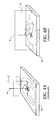
- FIGS. 4A and 4B are perspective views showing, from two orthogonal perspectives, key angles of interest for achieving suitable imaging conditions
- FIG. 5 is a plan view showing the sensor of the present invention attached to an x-ray cassette and the reference angles measured in one embodiment
- FIG. 6A shows a perspective view of the relationship between the x-ray head, a cassette in a level orientation, and the direction of gravity;
- FIG. 6B shows a perspective view of the relationship between the x-ray head, a cassette in a non-level orientation, and the direction of gravity;
- FIG. 7A is a perspective view of an imaging system of the present invention in one embodiment, with a measurement sensor disposed on the cassette;
- FIG. 7B is a perspective view of an imaging system of the present invention in another embodiment, with a measurement sensor disposed on the radiation head;
- FIG. 8 is a perspective view of an imaging system of the present invention in an alternate dual-sensor embodiment, with one sensor disposed on the cassette and the other sensor, on the radiation head;
- FIG. 9A is a perspective view showing how the housing of the sensor can be fitted onto the cassette
- FIG. 9B is a side view of the sensor taken along line 9 B- 9 B of FIG. 9A ;
- FIG. 10 is a perspective view of another embodiment of the housing of the sensor, in which magnets are used for coupling the sensor to components of the radiation imaging system;
- FIG. 11 is a perspective view of a radiation head that has the sensor of the present invention mounted thereon, in one embodiment
- FIG. 12 is a perspective view of a radiation head that has the sensor of the present invention mounted thereon, in an alternate embodiment
- FIG. 13 is a block diagram showing key components of the sensor apparatus of the present invention.
- FIG. 14 is a block diagram showing key components of the sensor apparatus of the present invention in an embodiment that utilizes a remotely located display component;
- FIG. 15 is a block diagram showing key components of the sensor apparatus of the present invention according to another embodiment.
- FIG. 16 is a logic flow diagram showing technician procedures for use of the sensor apparatus of the present invention in an embodiment where a single sensor is provided;
- FIG. 17 is a logic flow diagram showing technician procedures for use of the sensor apparatus of the present invention in an embodiment where two sensors are provided;
- FIG. 18 is a view of the sensor of the present invention in an embodiment having the display integrated as part of the sensor body;
- FIG. 19 is a view of the sensor of the present invention in an alternate embodiment having the display integrated as part of the sensor body;
- FIG. 20 shows a display monitor screen arranged for use with the sensor of the present invention, in a landscape orientation
- FIG. 21 shows a display monitor screen arranged for use with the sensor of the present invention, in a portrait orientation
- FIG. 22 shows a display monitor screen arranged for use with the sensor of the present invention, with display dials indicating angular orientations at a point in time.
- the apparatus and method of the present invention use three-axis, preferably inertial, measurement components and techniques for obtaining object orientation data that helps to align at the proper angle a radiation source and a two dimensional radiation image detection device.
- Embodiments of the present invention enable the technician to position the two-dimensional radiation image detection device, also referred to in this description as a computed radiography (CR) cassette, at a favorable angle for the patient, whether in a vertical, oblique, or horizontal position.
- the technician can then adjust the angle of the radiation head suitably for imaging, using information that is provided from sensors coupled to the cassette and x-ray head, where this information indicates the needed direction of adjustment for alignment correction.
- CR computed radiography
- FIG. 1 shows a known type of portable radiation imaging apparatus or system 10 comprising a radiation head 12 that houses an X-ray radiation source 14 .
- Radiation head 12 directs x-ray radiation toward the patient along a central axis O.
- Radiation head 12 has an adjustable position and angular orientation, thus allowing adjustment of central axis O to suit the requirements of an imaging session.
- the patient can be in a horizontal position, as shown in the example of FIG. 1 , or can be at an oblique or even vertical angle, depending on the type of image that must be obtained.
- a cassette 20 which serves as the two-dimensional radiation image detection device, has a photostimulable medium that records an image according to the radiation emitted from radiation source 14 .
- central axis O be at least substantially perpendicular to the surface of the medium within cassette 20 , that is, aligned with the normal N to the surface of cassette 20 .
- a target 18 typically provided by a projected beam of visible light, appears on the patient and helps the technician to aim radiation head 12 to a suitable location. Since radiation head 12 has both an adjustable position and orientation, target 18 may be aimed at a suitable location, given many combinations of position and orientation of radiation source 14 . Some combinations of positions and orientations of radiation head 12 may be suitable for an examination, while others may not.
- FIG. 2 shows an antiscatter grid 22 that is conventionally provided between cassette 20 and radiation source 14 to support x-ray imaging.
- Grid 22 presents another practical concern for alignment.
- the grid typically includes a series of lead strips 24 encased in an aluminum or carbon fiber material.
- the effectiveness of antiscatter grid 22 namely its ability to reduce the contribution of scattered radiation in an x-ray image, is dependent upon the relative position and orientation of both the grid and radiation head 12 .
- Strips 24 are generally parallel along their lengths, but are angled toward a focal line 28 . It is desirable to arrange a focal spot 26 for positioning radiation head 12 along focal line 28 .
- FIG. 3 shows one example of how radiation head 12 aligns along focal line 28 and indicates the relative positions of axis O and normal N.
- FIGS. 4 A and 4 B show, from two perspectives, key angles of interest for achieving suitable imaging conditions.
- the FIG. 4B view is in the same plane as the FIG. 4A view, but rotated 90 degrees.
- An angle ⁇ represents one angular component of the beam directed from the radiation source; an angle ⁇ represents another component of the beam.
- An angle ⁇ represents rotation about normal N. Given these angles, it can be appreciated that more than mere tilt measurement will be needed to obtain proper alignment of cassette 20 and radiation head 12 .
- FIG. 5 shows a sensor apparatus 30 according to one embodiment, coupled to the corner of cassette 20 .
- Sensor apparatus 30 preferably is of the inertial type that measures angular rate and acceleration for orthogonal x, y, and z axes, with the designations shown. Components and functions of a suitable sensor apparatus are described later in this specification.
- Angular rate sensors are widely used in airborne and vehicular apparatus for providing information on dynamic motion. To provide this type of information, angular rate sensors measure angular rates of rotation about particular axes and this data can be used to provide dynamic measurement of orientation angle. An angular rate sensor does not directly measure angle or orientation by itself, however, but measures rotational motion, that is, rotational speed. Integration of this motion over time then provides a measure of angle as a function of time. Unlike simple tilt sensors that merely report an angular difference with respect to gravity, angular rate sensors provide a complex amount of information that is continuously updated as the sensors are moved. This information can be used to obtain data on the angular difference with respect to directions other than the direction of gravity.
- FIGS. 6A and 6B show graphically how the inertial measurement sensor apparatus of the present invention is advantaged over tilt sensors as described by Tanaka et al. and as used commercially in the Siemens Mobilett unit and other equipment.
- FIG. 6A shows the limited conditions under which a tilt sensor 31 can provide an acceptable solution.
- cassette 20 is in a level orientation with respect to gravity.
- X-ray radiation head 12 projects a target light beam that is used to point radiation head 12 to the center of cassette 20 .
- radiation head 12 is always oriented to provide its beam at a normal to the surface of cassette 20 and cassette 20 must be level.
- a conceptual orientation sphere 37 can be visualized as shown in FIG.
- Tilt sensor 31 a can be mounted to x-ray radiation head 20 to indicate that x-ray radiation head 12 is oriented correctly, along focal grid line 28 . Tilt sensor 31 a indicates that x-ray radiation head 12 is in a level orientation. The distance from x-ray head 12 to the cassette 20 is adjusted to the focus distance of the grid. Thus, for the arrangement shown and described with reference to FIG. 6A , tilt sensors 31 a at radiation head 12 and 31 b at cassette 20 would be sufficient for providing the correct orientation for imaging.
- FIG. 6B illustrates what happens if the tilt sensor solution that works for the limited conditions shown in FIG. 6A is applied in a more general case.
- the same imaging components as those shown in FIG. 6A are used, but are oriented at a non-level angle relative to the direction of gravity.
- the tilt of cassette 20 is again measured with tilt sensor 31 b .
- radiation head 12 may be in any position along a circle of uncertainty 41 shown on sphere 37 while its tilt sensor 31 a reads the same tilt value as given in the initial reading of the tilt of cassette 20 .
- tilt sensor 31 a would report tilt at a position 43 , shown dotted in FIG. 6B , as the same as tilt at a position 45 .
- FIG. 6A also has a circle of uncertainty; however, this is positioned at the top of sphere 37 and is effectively small enough to be considered as a point.
- Orientation sensing using an inertial sensor apparatus 30 as in FIG 5 can provide sufficient information for achieving proper orientation of radiation head 12 and cassette 20 for the general conditions shown in FIG. 6B .
- FIGS. 7A and 7B show how sensor apparatus 30 is used, according to one embodiment.
- sensor apparatus 30 is adapted to be coupled to cassette 20 for obtaining a reference frame angular orientation measurement.
- sensor 30 can be de-coupled from cassette 20 and is adapted to be sequentially coupled to radiation head 12 , as is shown in FIG. 7B .
- Sensor apparatus 30 now reports to the technician, as described later in this specification, providing its differential angular orientation information relative to the reference angular orientation measurement that was initially made when it was coupled to cassette 20 ( FIG. 7A ). See the subsequent description regarding FIGS. 13 to 17 .
- This differential angular orientation information can then be used by the technician for adjusting the angular orientation of radiation head 12 to achieve the proper differential angle for the reference position of cassette 20 while target 18 is simultaneously pointed toward a suitable position.
- An optional computer workstation 32 and display 34 may be in communication with sensor apparatus 30 for tracking, computation, and reporting information to the technician, as is described subsequently.
- control logic can be self-contained within the sensor apparatus 30 .
- FIG. 8 shows how sensor apparatuses 30 a and 30 b are used in an alternate embodiment.
- an initial calibration is performed in order to align sensor apparatuses 30 a and 30 b so that both share the same reference setting. See the subsequent description regarding FIG. 17 .
- sensor apparatuses 30 a and 30 b can communicate to control logic what adjustments need to be made in order to achieve differential angular alignment.
- an external computer workstation 32 and display 34 may be used for this dual sensor 30 a / 30 b embodiment.
- sensor apparatus 30 can be coupled to cassette 20 , and thus to the photostimulable medium that records the image, in a number of ways.
- FIGS. 9A and 9B show perspective and end views for one embodiment, in which sensor apparatus 30 has a housing that is featured to fit onto a corner of cassette 20 . Opposing pairs of tabs 38 extend from housing 36 and provide the mechanism for maintaining a snug pressure fit against cassette 20 , whereby the technician can readily manually attach or remove sensor apparatus 30 .
- a pressure fit may be acceptable for registering sensor apparatus 30 to cassette 20 ; however, other embodiments can also be used.
- FIG. 10 shows housing 36 having a fitting arrangement using magnets 42 that would be attracted to metal structures in cassette 20 .
- sensor apparatus 30 be mounted to radiation head 12 during adjustment of head angle.
- the same fitting or some alternative fitting may be used for this purpose.
- FIG. 11 there is shown an embodiment with sensor apparatus 30 coupled to a handle 44 of radiation head 12 .
- This may use the pressure fit of FIGS. 9A and 9B or may use the magnetic approach shown in FIG. 10 , for example.
- Other types of fitting could be used, including, for example, pin-and-socket fitting, conventional thumbscrew or latched fasteners, and the like. It would be a significant advantage for sensor apparatus 30 to mount against either or both cassette 20 and radiation head 12 without requiring the use of tools.
- sensor apparatus 30 be coupled to either cassette 20 or radiation head 12 without requiring redesign of these components.
- Flexible hook-and-loop or hook-and-pile connectors such as VELCRO fasteners from Velcro Industries B. V., Amsterdam, NL, or some other type of separable flexible fastening device could alternately be used for coupling sensor apparatus 30 to either cassette 20 or to radiation head 12 or both.
- the perspective view of FIG. 12 shows another embodiment, with sensor apparatus 30 attached to the side of radiation head 12 . In this case, computation must take into account the different orientations of sensor apparatus 30 with respect to cassette 20 and radiation head 12 .
- coupling housing 36 to an individual make and model of radiation head 12 may require an additional bracket or other hardware.
- Each model of radiation head 12 can have a unique design, requiring a unique solution for making this attachment.
- cassette 20 it is generally preferred to mount sensor apparatus 30 against a corner of the housing of the cassette, as shown in FIGS. 5 and 9A , for example. Or, it may be desirable to mount sensor apparatus 30 along an edge. However, other arrangements are possible, including arrangements wherein sensor apparatus 30 is not removable, but is built in to cassette 20 in some way.
- FIG. 13 there is shown a block diagram of the basic components of one embodiment of a sensor apparatus 30 .
- a sensor module 40 that provides inertial sensing for angular rate and acceleration with respect to three orthogonal axes, conventionally x, y, and z as was shown in FIG. 5 .
- MEMS Micro-ElectroMechanical Systems
- Sensor module 40 may also detect other conditions, such as proper operating temperature (indicating warmup is completed and equipment accuracy can be assumed).
- a control logic processor 58 is in communication with sensor module 40 for obtaining the angular rate and acceleration data at regular sampling intervals. With the FalconGX module, for example, sampling can be performed at 50 times per second. Control logic processor 58 may be an on-board microprocessor or other dedicated control logic device. Alternately, such as when a high degree of computation is required, a communication link may be provided to an external processor, such as a computer workstation or other device.
- Storage 56 can be provided for maintaining a memory storage buffer of some portion of the sampled data from sensor module 40 .
- a display 54 of some type is provided as an indicator responsive to orientation data from sensor module 40 and providing some visible and/or audible indication of relative angular orientation, as an aid to help the technician to ascertain in which direction adjustment is needed.
- a technician interface 60 is provided and may include a control console for command entry, plus such devices as reset or zeroing switches used for calibration, for example.
- Sensor apparatus 30 in FIG. 13 provides a complete system, but one or more components may be located remotely, rather than integrated on the same circuit board, for example, used for sensor module 40 .
- Other components may be optional or allow a wide scope for embodiment.
- control logic processor 58 can use an external device or system, or the function of control logic processor 58 can be distributed among one or more separate processors.
- storage 56 can be located on a single device or may be stored on a host workstation or other device that provides processing computation for sensor 30 .
- Display 54 can be mounted directly onto housing 36 or may be a conventional Cathode-Ray Tube (CRT) display, such as one connected as part of a conventional computer workstation. Or, display 54 can be simply a numeric display device, using patterned Light-Emitting Diodes (LEDs) or other devices to display values for any or all of the motion sensed by sensor module 40 .
- CTR Cathode-Ray Tube
- both sensor apparatuses 30 could have the same design, with appropriate programming that designates one sensor apparatus 30 b as the benchmark (mounted on cassette 20 in most cases) and the other sensor apparatus 30 a as variable.
- display 54 on the benchmark unit may be zeroed or blank; on the other sensor 30 that attaches to radiation head 12 , display 54 would be active.
- the function of display 54 could be enhanced or replaced by an audible tone or signal of some kind.
- a variable audio tone or clicking may be used to indicate to the technician that adjustment is needed in one or more directions or that suitable adjustment has been achieved.
- FIG. 14 shows one embodiment following the basic model given in FIG. 13 .
- power supply 48 is a battery.
- a power switch 46 is provided, as is a power indicator 50 .
- a communications circuit 52 such as a wireless RF transceiver or, alternately, a wired communications module, enables transmission of measurement data from sensor module 40 to an external device. In the embodiment of FIG. 14 , this data goes to external control logic processor 58 and its corresponding display 54 .
- sensor apparatus 30 could be in communication with a series of motors and motion control devices, such as for the sensor apparatus 30 a component coupled to radiation head 12 in the embodiment of FIG. 8 .
- FIG. 15 shows another embodiment of sensor apparatus 30 , again following the basic model given in FIG. 13 .
- sensor module 40 connects to a local control logic processor 58 , but can also communicate through communications circuit 52 to some other computer or similar control logic device as well.
- Technician interface 60 includes a touchpad for entering desired values or for zeroing sensor apparatus 30 at the beginning of a positioning cycle.
- Display 54 is provided directly on sensor apparatus 30 in this embodiment.
- Control logic processor 58 functions typically include transmitting control signals to sensor module 40 and obtaining the regularly updated data from this component. Other functions such as reset and calibration can also be performed through commands from control logic processor 58 , thus enabling remote reset, for example. Algorithms for computing angle based on the sensor data may be stored and executed on control logic processor 58 on sensor apparatus 30 itself. However, it can be more advantageous to transmit this data to an external computer workstation or other processor for efficient processing and display.
- FIGS. 14 and 15 can be used to provide movement information to, or to obtain commands from, a number of different types of external devices, both wireless and wired.
- communications circuit 52 can be used to display or provide motion information to a hand-held computer or personal communications device, such as a cell phone, Personal Digital Assistant (PDA), and the like. In this way, orientation information and commands can be viewed and entered on a remote device that is easily accessible to the technician.
- PDA Personal Digital Assistant
- FIGS. 7 A/ 7 B and 8 For the basic single- and dual-sensor embodiments shown in FIGS. 7 A/ 7 B and 8 respectively, it is useful to consider the sequence of operations performed by the technician in order to set up the position of the radiation image detection device (cassette 20 ) and radiation head 12 . Turning now to the flow chart of FIG. 16 , the basic steps for system operation with the single sensor embodiment are shown.
- a sensor setup step 100 the technician first mounts sensor apparatus 30 on the side of cassette 20 and positions cassette 20 in the desired position for the image that is needed. The technician then uses the aiming light beam on the unit to project target 18 ( FIG. 1 ) on the patient, to ensure that the cassette and radiation head are properly positioned relative to each other for image capture.
- a reset step 110 then follows, in which the technician zeroes sensor apparatus 30 by pressing a switch or making some other suitable command entry. This sets the stable angular orientation of sensor apparatus 30 as the benchmark orientation. Motion from this point can be calculated by processor 58 to determine how much sensor apparatus 30 is shifted angularly away from this original orientation at a later point in time.
- a sensor repositioning step 120 the technician removes sensor apparatus 30 from its position and orientation on or alongside cassette 20 and second attaches it to the appropriate structures on radiation head 12 .
- a feedback review step 130 is executed, during which the technician reviews the feedback generated by sensor apparatus 30 in its position against radiation head 12 .
- the outputs of sensor apparatus 30 will be indicative of its change in orientation from its benchmark orientation at cassette 20 . From those outputs, the technician determines how to align radiation head 12 properly to cassette 20 . Where an oblique angle of incidence is desired, as in the case shown in FIGS. 4A and 4B for example, the technician carefully aligns the angle of radiation head 12 and aims target 18 appropriately.
- a decision step 140 the technician determines whether or not the adjustment is suitable and imaging can proceed. Where additional adjustment is necessary, the technician carries out a head repositioning step 150 for making the minor adjustment. Where no additional adjustment is necessary, an image capture step 160 follows, during which the technician completes preparation and obtains the x-ray image.
- a base calibration step 200 is executed first.
- sensor apparatuses 30 a and 30 b are aligned to each other. This is most readily accomplished by simply holding sensor apparatuses 30 a and 30 together in about the same position, then entering a base calibration command for each sensor apparatus 30 a , 30 b .
- a patient side setup step 210 is next executed. During this procedure, the technician mounts sensor apparatus 30 b on the side of cassette 20 and positions cassette 20 in the desired position for the image that is needed.
- An initial head position step 220 is then carried out.
- the technician makes initial adjustments to the orientation of radiation head 12 , according to information provided from sensor apparatuses 30 a and 30 b . This may involve rotation about more than one axis as the technician observes displayed values on display 54 ( FIGS. 13-15 ) to ascertain the proper direction and amount of movement needed.
- the technician performs a decision step 230 .
- the technician determines whether or not the adjustment is suitable and imaging can proceed. Where additional adjustment is necessary, the technician carries out a readjustment step 240 and makes the desired minor adjustments. Where no additional adjustment is necessary, an image capture step 250 follows, during which the technician completes preparation and obtains the x-ray image.
- FIGS. 16 and 17 are exemplary, provided to illustrate typical operation, and should not be considered as limiting; a number of other possible operation sequences could be executed. Also, it is instructive to note that there is a time factor involved, since accumulated error and noise can cause drift and lead to positional errors, as was noted earlier. It must be observed that there is always some element of noise and some element of error that can have a compounding effect, degrading calculation results over time. Thus, timeout would be one error condition not noted in FIG. 16 or 17 , but capable of overriding technician procedures and requiring recalibration (that is, re-zeroing) of the device.
- Self-checks performed by sensor apparatus 30 include temperature measurement, to ascertain that the device has achieved a preferred operating temperature range.
- Sensor module 40 components are also sensitive to abrupt motion, such as if sensor apparatus 30 or cassette 20 were dropped or bumped during movement by the technician. An error condition of this type would prevent operation until recalibration (re-zeroing) is performed by the technician.
- sensor 30 has an on-board bank of indicators of various types that assist the technician in use of the device.
- Orientation displays 66 described subsequently in more detail, give a graphic indication of orientation data obtained with respect to each axis.
- Operational indicators 68 illuminate to indicate status of the power source or may indicate an error condition requiring recalibration.
- Embodiments with display 54 functions incorporated on sensor 30 itself would be particularly advantageous for either the single sensor arrangement of FIGS. 7A and 7B or the dual-sensor arrangement described earlier with reference to FIG. 8 .
- the technician can make adjustments of radiation head 12 orientation while viewing display 54 directly.
- sensor 30 a could have the built-in display 54 embodiment of FIG. 18 .
- FIG. 19 shows an embodiment of display 54 having additional capabilities.
- a numerical or text display portion 82 is provided, with variable text fields for listing data values themselves, possibly along with relevant information for the technician such as showing how to interpret the various data fields that are given.
- FIG. 22 shows positional displays 66 as they might appear on an technician device that is separate from sensor apparatus 30 , such as a wireless device, that acts as a control console 85 .
- a display dial 84 indicates rotation about the z axis.
- Another display dial 86 indicates rotation about the y axis (transformed to ⁇ in FIG. 4A ), such as viewed from the feet of the patient.
- another display dial 88 indicates rotation about the x axis (transformed to ⁇ in FIG. 4B ), such as viewed from the left side of the patient.
- An orientation icon 76 shows the basic layout of the cassette for imaging, whether landscape or portrait, with an icon 92 for sensor apparatus 30 visible on one corner.
- a reset switch 78 allows the technician to control console 85 to initiate zeroing of sensor apparatus 30 in a remote manner. This would be advantageous, for example, where sensor apparatus 30 is difficult to access in its position behind the patient.
- a conventional computer monitor can alternately be used for display 54 .
- FIGS. 20 and 21 there are shown example displays that might appear on a touchscreen display 80 .
- Command entry controls 90 would be buttons displayed on touchscreen display 80 and would allow the technician to initiate calibration and interactively view motion changes as sensor apparatus 30 is positioned.
- Icon 76 can be oriented on-screen as it is positioned behind the patient and may additionally show the position of sensor apparatus 30 , as is indicated by a sensor icon 92 in FIGS. 20 and 21 .
- Sensor apparatus 30 does not yield a stable tilt or angular value, but provides constantly updated angular rate and acceleration data, which must be integrated in order to obtain accurate positional information.
- control processing logic for executing this task, with numerous ways of communicating the measurement data between sensor module 40 and the control logic processor.
Abstract
Description
- 10 Portable radiation imaging apparatus
- 12 Radiation head
- 14 Radiation source
- 18, 18 a Target
- 20 Cassette
- 22 Antiscatter grid
- 24 Lead strips
- 26 Focal spot
- 28 Focal line
- 30, 30 a, 30 b Sensor apparatus, inertial
- 31 a, 31 b Tilt sensors
- 32 Computer workstation
- 34 Display
- 36 Housing
- 37 Orientation sphere
- 38 Tab
- 40 Sensor module
- 41 Circle of uncertainty
- 42 Magnet
- 43, 45 Position of
radiation head 12 - 46 Switch
- 48 Power supply
- 50 Indicator
- 52 Communications circuit
- 54 Display
- 56 Storage
- 58 Control logic processor
- 60 Technician interface
- 62 Power supply
- 66 Orientation display
- 68 Operational indicator
- 76 Cassette icon
- 80 Display
- 82 Text display portion
- 84, 86, 88 Display dial
- 85 Console
- 90 Controls
- 92 Sensor icon
- 100 Sensor setup step
- 110 Reset step
- 120 Sensor repositioning step
- 130 Feedback review step
- 140 Decision step
- 150 Head reorienting or repositioning step
- 160 Image capture step
- 200 Base calibration step
- 210 Patient side setup step
- 220. Initial head position step
- 230 Decision step
- 240 Readjustment step
- 250 Image capture step
- N. Normal to
cassette 20 - O. Central axis of x-ray radiation
- α, β, γ. Angle
Claims (22)
Priority Applications (2)
| Application Number | Priority Date | Filing Date | Title |
|---|---|---|---|
| US11/924,715 US7744279B2 (en) | 2006-11-02 | 2007-10-26 | Orientation sensing apparatus for radiation imaging system |
| PCT/US2007/022871 WO2008054717A2 (en) | 2006-11-02 | 2007-10-30 | Position sensing apparatus for radiation imaging system |
Applications Claiming Priority (2)
| Application Number | Priority Date | Filing Date | Title |
|---|---|---|---|
| US86397606P | 2006-11-02 | 2006-11-02 | |
| US11/924,715 US7744279B2 (en) | 2006-11-02 | 2007-10-26 | Orientation sensing apparatus for radiation imaging system |
Publications (2)
| Publication Number | Publication Date |
|---|---|
| US20080130837A1 US20080130837A1 (en) | 2008-06-05 |
| US7744279B2 true US7744279B2 (en) | 2010-06-29 |
Family
ID=39338660
Family Applications (1)
| Application Number | Title | Priority Date | Filing Date |
|---|---|---|---|
| US11/924,715 Expired - Fee Related US7744279B2 (en) | 2006-11-02 | 2007-10-26 | Orientation sensing apparatus for radiation imaging system |
Country Status (2)
| Country | Link |
|---|---|
| US (1) | US7744279B2 (en) |
| WO (1) | WO2008054717A2 (en) |
Cited By (16)
| Publication number | Priority date | Publication date | Assignee | Title |
|---|---|---|---|---|
| US20110249799A1 (en) * | 2010-04-13 | 2011-10-13 | Lalena Michael C | Display of aec sensor location |
| US20110306863A1 (en) * | 2010-06-15 | 2011-12-15 | Jason Koshnitsky | Patient alignment system for diagnostic and therapeutic procedures |
| US20110305319A1 (en) * | 2010-06-14 | 2011-12-15 | General Electric Company | Position sensing device for a portable detection device |
| US8821017B2 (en) | 2010-04-13 | 2014-09-02 | Carestream Health, Inc. | Projector as collimator light |
| US8827554B2 (en) | 2010-04-13 | 2014-09-09 | Carestream Health, Inc. | Tube alignment for mobile radiography system |
| US8873712B2 (en) | 2010-04-13 | 2014-10-28 | Carestream Health, Inc. | Exposure control using digital radiography detector |
| US20150069256A1 (en) * | 2013-09-12 | 2015-03-12 | Canon Kabushiki Kaisha | Radiation generating apparatus and radiation imaging apparatus |
| US20150104185A1 (en) * | 2014-03-25 | 2015-04-16 | Osram Sylvania Inc. | Techniques for raster line alignment in light-based communication |
| US20150250442A1 (en) * | 2014-03-10 | 2015-09-10 | Kabushiki Kaisha Toshiba | X-ray image diagnostic apparatus |
| US10016173B2 (en) | 2012-02-22 | 2018-07-10 | Carestream Health, Inc. | Mobile radiographic apparatus/methods with tomosynthesis capability |
| US10165992B2 (en) | 2010-10-18 | 2019-01-01 | Carestream Health, Inc. | X-ray imaging systems and devices |
| US10517562B2 (en) | 2016-09-30 | 2019-12-31 | General Electric Company | Mobile radiography system and method for aligning mobile radiography system |
| US10531850B2 (en) | 2017-09-07 | 2020-01-14 | General Electric Company | Mobile X-ray imaging with detector docking within a spatially registered compartment |
| US10653385B2 (en) | 2013-08-05 | 2020-05-19 | Koninklijke Philips N.V. | Tube alignment functionality for mobile radiography systems |
| US10893842B2 (en) | 2018-02-08 | 2021-01-19 | Covidien Lp | System and method for pose estimation of an imaging device and for determining the location of a medical device with respect to a target |
| US20220202388A1 (en) * | 2020-12-25 | 2022-06-30 | Shimadzu Corporation | X-ray imaging apparatus and positional deviation detection unit for x-ray imaging apparatus |
Families Citing this family (22)
| Publication number | Priority date | Publication date | Assignee | Title |
|---|---|---|---|---|
| GB2440588B (en) * | 2006-08-04 | 2009-09-09 | Symetrica Ltd | Gamma-Ray detector |
| US7783008B2 (en) * | 2007-03-30 | 2010-08-24 | General Electric Company | Digital radiograph patient positioning system and method |
| JP4847492B2 (en) * | 2008-06-02 | 2011-12-28 | キヤノン株式会社 | Radiation detection apparatus, radiation detection system, and control method thereof |
| JP5288896B2 (en) * | 2008-06-11 | 2013-09-11 | 富士フイルム株式会社 | Electronic cassette |
| JP2010184025A (en) * | 2009-02-12 | 2010-08-26 | Fujifilm Corp | Radiation imaging system, power supplying apparatus, charging apparatus, and radiation imaging method |
| DE102010008551B4 (en) * | 2010-02-19 | 2020-02-06 | Siemens Healthcare Gmbh | X-ray system |
| DE102010008552B4 (en) * | 2010-02-19 | 2014-11-13 | Siemens Aktiengesellschaft | X-ray system |
| DE102010020782A1 (en) * | 2010-05-18 | 2011-11-24 | Siemens Aktiengesellschaft | X-ray device e.g. C-arm rotation angiography device, for e.g. three-dimensional imaging of patient, has determination units connected with X-ray source and detector to determine movement and/or position of source and detector, respectively |
| US8917815B2 (en) | 2010-06-21 | 2014-12-23 | Zachary A. Miller | Adjustable dynamic filter |
| US8287187B2 (en) | 2010-06-21 | 2012-10-16 | Miller Zachary A | Adjustable dynamic X-ray filter |
| DE102010027671A1 (en) * | 2010-07-20 | 2012-01-26 | Siemens Aktiengesellschaft | X-ray system for providing three-dimensional image of tissue of patient, has X-ray radiation sources arranged on C-shaped arm, where actual position is determined at X-ray radiation source or at X-ray detector by position sensor |
| US20120018641A1 (en) * | 2010-07-22 | 2012-01-26 | Fujifilm Corporation | Radiation image capturing device, radiation image capturing system, and radiation image capturing method |
| WO2012063181A1 (en) * | 2010-11-08 | 2012-05-18 | Koninklijke Philips Electronics N.V. | Module carrier attachment |
| US8821015B2 (en) | 2011-03-08 | 2014-09-02 | Carestream Health, Inc. | Alignment apparatus for X-ray imaging system |
| DE102011075527A1 (en) * | 2011-05-09 | 2012-11-15 | Fraunhofer-Gesellschaft zur Förderung der angewandten Forschung e.V. | Radiation system and calibration of the same |
| AU2013252899A1 (en) | 2012-04-24 | 2014-10-30 | Portavision Medical Llc | Mobile imaging system and method |
| US20150023468A1 (en) * | 2013-07-17 | 2015-01-22 | General Electric Company | System and method for reducing a weight of an x-ray source |
| US10213180B2 (en) | 2016-09-14 | 2019-02-26 | Dental Imaging Technologies Corporation | Multiple-dimension imaging sensor with operation based on magnetic field detection |
| US10299742B2 (en) | 2016-09-14 | 2019-05-28 | Dental Imaging Technologies Corporation | Multiple-dimension imaging sensor with fault condition detection |
| US10932733B2 (en) | 2016-09-14 | 2021-03-02 | Dental Imaging Technologies Corporation | Multiple-dimension imaging sensor with operation based on movement detection |
| US10299741B2 (en) | 2016-09-14 | 2019-05-28 | Dental Imaging Technologies Corporation | Multiple-dimension imaging sensor and state-based operation of an imaging system including a multiple-dimension imaging sensor |
| US11944475B2 (en) | 2019-04-02 | 2024-04-02 | Carestream Health, Inc. | System and method for mobile radiography deployment |
Citations (15)
| Publication number | Priority date | Publication date | Assignee | Title |
|---|---|---|---|---|
| US4752948A (en) | 1986-12-01 | 1988-06-21 | University Of Chicago | Mobile radiography alignment device |
| US5241578A (en) | 1991-12-02 | 1993-08-31 | Arch Development Corporation | Optical grid alignment system for portable radiography and portable radiography apparatus incorporating same |
| US5388143A (en) | 1993-11-26 | 1995-02-07 | Arch Development Corporation | Alignment method for radiography and radiography apparatus incorporating same |
| US5690107A (en) * | 1995-07-08 | 1997-11-25 | Lap Gmbh Laser Applikationen | Method for positioning and marking a patient at a diagnostic apparatus |
| US5828722A (en) | 1996-05-17 | 1998-10-27 | Sirona Dental Systems Gmbh & Co., Kg | X-ray diagnostic apparatus for tomosynthesis having a detector that detects positional relationships |
| EP1000582A2 (en) | 1998-11-12 | 2000-05-17 | Picker International, Inc. | Apparatus and method for imaging |
| US6154522A (en) | 1999-02-11 | 2000-11-28 | Mcdonnell Douglas Corporation | Method, system and apparatus for aiming a device emitting a radiant beam |
| EP1163880A2 (en) | 2000-05-23 | 2001-12-19 | GE Medical Systems Global Technology Company LLC | Method and system for determining a source-T0-image distance in a digital imaging system |
| US20020150215A1 (en) * | 2001-04-11 | 2002-10-17 | Barnes Gary T. | Mobile radiography system and process |
| US20040113778A1 (en) * | 1996-05-30 | 2004-06-17 | Script Michael H. | Portable motion detector and alarm system and method |
| DE19611705B4 (en) | 1996-03-25 | 2005-01-27 | Siemens Ag | X-ray system |
| US20050033510A1 (en) * | 2003-08-08 | 2005-02-10 | Mitsubishi Denki Kabushiki Kaisha | Vehicle-mounted information apparatus |
| US20050058244A1 (en) | 2000-11-15 | 2005-03-17 | Fuji Photo Film Co., Ltd. | Portable radiation imaging system and a radiation image detection device equipped with an angular signal output means |
| US20060109958A1 (en) | 2004-11-24 | 2006-05-25 | Ertel Jason R | Method and system of aligning x-ray detector for data acquisition |
| WO2007005683A2 (en) | 2005-07-01 | 2007-01-11 | The Regents Of The University Of California | Method and apparatus for angle of inclination acquisition and display on radiographic image |
-
2007
- 2007-10-26 US US11/924,715 patent/US7744279B2/en not_active Expired - Fee Related
- 2007-10-30 WO PCT/US2007/022871 patent/WO2008054717A2/en active Application Filing
Patent Citations (17)
| Publication number | Priority date | Publication date | Assignee | Title |
|---|---|---|---|---|
| US4752948A (en) | 1986-12-01 | 1988-06-21 | University Of Chicago | Mobile radiography alignment device |
| US5241578A (en) | 1991-12-02 | 1993-08-31 | Arch Development Corporation | Optical grid alignment system for portable radiography and portable radiography apparatus incorporating same |
| US5388143A (en) | 1993-11-26 | 1995-02-07 | Arch Development Corporation | Alignment method for radiography and radiography apparatus incorporating same |
| US5690107A (en) * | 1995-07-08 | 1997-11-25 | Lap Gmbh Laser Applikationen | Method for positioning and marking a patient at a diagnostic apparatus |
| DE19611705B4 (en) | 1996-03-25 | 2005-01-27 | Siemens Ag | X-ray system |
| US5828722A (en) | 1996-05-17 | 1998-10-27 | Sirona Dental Systems Gmbh & Co., Kg | X-ray diagnostic apparatus for tomosynthesis having a detector that detects positional relationships |
| US20040113778A1 (en) * | 1996-05-30 | 2004-06-17 | Script Michael H. | Portable motion detector and alarm system and method |
| US6461040B1 (en) * | 1998-11-12 | 2002-10-08 | Koninklijke Philips Electronics N.V. | Apparatus and method to correct for position errors in diagnostic imaging |
| EP1000582A2 (en) | 1998-11-12 | 2000-05-17 | Picker International, Inc. | Apparatus and method for imaging |
| US6154522A (en) | 1999-02-11 | 2000-11-28 | Mcdonnell Douglas Corporation | Method, system and apparatus for aiming a device emitting a radiant beam |
| EP1163880A2 (en) | 2000-05-23 | 2001-12-19 | GE Medical Systems Global Technology Company LLC | Method and system for determining a source-T0-image distance in a digital imaging system |
| US6435716B1 (en) * | 2000-05-23 | 2002-08-20 | Ge Medical Systems Global Technology Company, Llc | Method and system for determining a source-to-image distance in a digital imaging system |
| US20050058244A1 (en) | 2000-11-15 | 2005-03-17 | Fuji Photo Film Co., Ltd. | Portable radiation imaging system and a radiation image detection device equipped with an angular signal output means |
| US20020150215A1 (en) * | 2001-04-11 | 2002-10-17 | Barnes Gary T. | Mobile radiography system and process |
| US20050033510A1 (en) * | 2003-08-08 | 2005-02-10 | Mitsubishi Denki Kabushiki Kaisha | Vehicle-mounted information apparatus |
| US20060109958A1 (en) | 2004-11-24 | 2006-05-25 | Ertel Jason R | Method and system of aligning x-ray detector for data acquisition |
| WO2007005683A2 (en) | 2005-07-01 | 2007-01-11 | The Regents Of The University Of California | Method and apparatus for angle of inclination acquisition and display on radiographic image |
Cited By (29)
| Publication number | Priority date | Publication date | Assignee | Title |
|---|---|---|---|---|
| US8873712B2 (en) | 2010-04-13 | 2014-10-28 | Carestream Health, Inc. | Exposure control using digital radiography detector |
| US8867705B2 (en) * | 2010-04-13 | 2014-10-21 | Carestream Health, Inc. | Display of AEC sensor location |
| US20110249799A1 (en) * | 2010-04-13 | 2011-10-13 | Lalena Michael C | Display of aec sensor location |
| US9155509B2 (en) | 2010-04-13 | 2015-10-13 | Carestream Health, Inc. | Tube alignment for mobile radiography system |
| US8824634B2 (en) | 2010-04-13 | 2014-09-02 | Carestream Health, Inc. | Configurable AEC sensor for an X-ray system |
| US8821017B2 (en) | 2010-04-13 | 2014-09-02 | Carestream Health, Inc. | Projector as collimator light |
| US8827554B2 (en) | 2010-04-13 | 2014-09-09 | Carestream Health, Inc. | Tube alignment for mobile radiography system |
| US20110305319A1 (en) * | 2010-06-14 | 2011-12-15 | General Electric Company | Position sensing device for a portable detection device |
| US8690426B2 (en) * | 2010-06-14 | 2014-04-08 | General Electric Company | Position sensing device for a portable detection device |
| US20110306863A1 (en) * | 2010-06-15 | 2011-12-15 | Jason Koshnitsky | Patient alignment system for diagnostic and therapeutic procedures |
| US10165992B2 (en) | 2010-10-18 | 2019-01-01 | Carestream Health, Inc. | X-ray imaging systems and devices |
| US10463325B2 (en) | 2012-02-22 | 2019-11-05 | Carestream Health, Inc. | Mobile radiographic apparatus/methods with tomosynthesis capability |
| US10016173B2 (en) | 2012-02-22 | 2018-07-10 | Carestream Health, Inc. | Mobile radiographic apparatus/methods with tomosynthesis capability |
| US10653385B2 (en) | 2013-08-05 | 2020-05-19 | Koninklijke Philips N.V. | Tube alignment functionality for mobile radiography systems |
| US9414795B2 (en) * | 2013-09-12 | 2016-08-16 | Canon Kabushiki Kaisha | Radiation generating apparatus and radiation imaging apparatus |
| US20150069256A1 (en) * | 2013-09-12 | 2015-03-12 | Canon Kabushiki Kaisha | Radiation generating apparatus and radiation imaging apparatus |
| US9962139B2 (en) * | 2014-03-10 | 2018-05-08 | Toshiba Medical Systems Corporation | X-ray image diagnostic apparatus that acquires position information associated with a table top |
| US20150250442A1 (en) * | 2014-03-10 | 2015-09-10 | Kabushiki Kaisha Toshiba | X-ray image diagnostic apparatus |
| US9621266B2 (en) * | 2014-03-25 | 2017-04-11 | Osram Sylvania Inc. | Techniques for raster line alignment in light-based communication |
| US9871589B2 (en) * | 2014-03-25 | 2018-01-16 | Osram Sylvania Inc. | Techniques for raster line alignment in light-based communication |
| US20170170899A1 (en) * | 2014-03-25 | 2017-06-15 | Osram Sylvania Inc. | Techniques for Raster Line Alignment in Light-Based Communication |
| US20150104185A1 (en) * | 2014-03-25 | 2015-04-16 | Osram Sylvania Inc. | Techniques for raster line alignment in light-based communication |
| US10517562B2 (en) | 2016-09-30 | 2019-12-31 | General Electric Company | Mobile radiography system and method for aligning mobile radiography system |
| US10531850B2 (en) | 2017-09-07 | 2020-01-14 | General Electric Company | Mobile X-ray imaging with detector docking within a spatially registered compartment |
| US10893842B2 (en) | 2018-02-08 | 2021-01-19 | Covidien Lp | System and method for pose estimation of an imaging device and for determining the location of a medical device with respect to a target |
| US11364004B2 (en) | 2018-02-08 | 2022-06-21 | Covidien Lp | System and method for pose estimation of an imaging device and for determining the location of a medical device with respect to a target |
| US11712213B2 (en) | 2018-02-08 | 2023-08-01 | Covidien Lp | System and method for pose estimation of an imaging device and for determining the location of a medical device with respect to a target |
| US11896414B2 (en) | 2018-02-08 | 2024-02-13 | Covidien Lp | System and method for pose estimation of an imaging device and for determining the location of a medical device with respect to a target |
| US20220202388A1 (en) * | 2020-12-25 | 2022-06-30 | Shimadzu Corporation | X-ray imaging apparatus and positional deviation detection unit for x-ray imaging apparatus |
Also Published As
| Publication number | Publication date |
|---|---|
| WO2008054717A9 (en) | 2008-06-19 |
| WO2008054717A3 (en) | 2008-09-18 |
| US20080130837A1 (en) | 2008-06-05 |
| WO2008054717A2 (en) | 2008-05-08 |
Similar Documents
| Publication | Publication Date | Title |
|---|---|---|
| US7744279B2 (en) | Orientation sensing apparatus for radiation imaging system | |
| US9155509B2 (en) | Tube alignment for mobile radiography system | |
| US8821017B2 (en) | Projector as collimator light | |
| US20090086926A1 (en) | Exposure centering apparatus for imaging system | |
| EP1778090B1 (en) | Arrangement in connection with intra-oral x-ray imaging | |
| EP3223706B1 (en) | X-ray apparatus | |
| US20090041201A1 (en) | Alignment apparatus for imaging system | |
| US7535411B2 (en) | System and method for detecting drifts in calibrated tracking systems | |
| CN103415252B (en) | For the alignment device of x-ray imaging system | |
| US20060257816A1 (en) | Arrangement for dental imaging | |
| US7806591B2 (en) | Alignment apparatus for imaging system using reflective element | |
| FI125516B (en) | Collimator device in connection with intraoral X-ray | |
| US20040024309A1 (en) | System for monitoring the position of a medical instrument with respect to a patient's body | |
| US20200214682A1 (en) | Methods and apparatuses for tele-medicine | |
| US20140194742A1 (en) | Ultrasound imaging system and method | |
| JP2012000452A (en) | Position sensing device for portable detection device | |
| EP2920547B1 (en) | System and method for measuring the relative positions of rotary components | |
| JP3135068B2 (en) | Position tracking and image generation system for medical applications using a reference unit fixed to the patient's head | |
| JP6363229B2 (en) | Ultrasonic data collection | |
| EP2836788B1 (en) | Mobile display unit for showing graphic information which represents an arrangement of physical components | |
| CN219758511U (en) | Laser distance measuring device | |
| JPH112676A (en) | Sonic pointer | |
| CN214128491U (en) | Capsule positioning system | |
| KR102296413B1 (en) | Detecting system of medical radiation and method for detecting medical radiation using the same | |
| CN117433412A (en) | Laser tracker head aiming control method and system |
Legal Events
| Date | Code | Title | Description |
|---|---|---|---|
| AS | Assignment |
Owner name: CARESTREAM HEALTH, INC., NEW YORK Free format text: ASSIGNMENT OF ASSIGNORS INTEREST;ASSIGNORS:HEATH, MICHAEL D.;LO, YAWCHENG;LEVY, TERESA M.;AND OTHERS;REEL/FRAME:020530/0572;SIGNING DATES FROM 20080129 TO 20080208 Owner name: CARESTREAM HEALTH, INC.,NEW YORK Free format text: ASSIGNMENT OF ASSIGNORS INTEREST;ASSIGNORS:HEATH, MICHAEL D.;LO, YAWCHENG;LEVY, TERESA M.;AND OTHERS;SIGNING DATES FROM 20080129 TO 20080208;REEL/FRAME:020530/0572 |
|
| FEPP | Fee payment procedure |
Free format text: PAYOR NUMBER ASSIGNED (ORIGINAL EVENT CODE: ASPN); ENTITY STATUS OF PATENT OWNER: LARGE ENTITY |
|
| STCF | Information on status: patent grant |
Free format text: PATENTED CASE |
|
| AS | Assignment |
Owner name: CREDIT SUISSE AG, CAYMAN ISLANDS BRANCH, NEW YORK Free format text: INTELLECTUAL PROPERTY SECURITY AGREEMENT;ASSIGNORS:CARESTREAM HEALTH, INC.;CARESTREAM DENTAL, LLC;QUANTUM MEDICAL IMAGING, L.L.C.;AND OTHERS;REEL/FRAME:026269/0411 Effective date: 20110225 |
|
| AS | Assignment |
Owner name: CARESTREAM HEALTH, INC., NEW YORK Free format text: RELEASE OF SECURITY INTEREST IN INTELLECTUAL PROPERTY (SECOND LIEN);ASSIGNOR:CREDIT SUISSE AG, CAYMAN ISLANDS BRANCH;REEL/FRAME:027851/0812 Effective date: 20110225 |
|
| AS | Assignment |
Owner name: CREDIT SUISSE AG, CAYMAN ISLANDS BRANCH, NEW YORK Free format text: AMENDED AND RESTATED INTELLECTUAL PROPERTY SECURITY AGREEMENT (FIRST LIEN);ASSIGNORS:CARESTREAM HEALTH, INC.;CARESTREAM DENTAL LLC;QUANTUM MEDICAL IMAGING, L.L.C.;AND OTHERS;REEL/FRAME:030711/0648 Effective date: 20130607 |
|
| AS | Assignment |
Owner name: CREDIT SUISSE AG, CAYMAN ISLANDS BRANCH, NEW YORK Free format text: SECOND LIEN INTELLECTUAL PROPERTY SECURITY AGREEMENT;ASSIGNORS:CARESTREAM HEALTH, INC.;CARESTREAM DENTAL LLC;QUANTUM MEDICAL IMAGING, L.L.C.;AND OTHERS;REEL/FRAME:030724/0154 Effective date: 20130607 |
|
| FPAY | Fee payment |
Year of fee payment: 4 |
|
| MAFP | Maintenance fee payment |
Free format text: PAYMENT OF MAINTENANCE FEE, 8TH YEAR, LARGE ENTITY (ORIGINAL EVENT CODE: M1552) Year of fee payment: 8 |
|
| FEPP | Fee payment procedure |
Free format text: MAINTENANCE FEE REMINDER MAILED (ORIGINAL EVENT CODE: REM.); ENTITY STATUS OF PATENT OWNER: LARGE ENTITY |
|
| LAPS | Lapse for failure to pay maintenance fees |
Free format text: PATENT EXPIRED FOR FAILURE TO PAY MAINTENANCE FEES (ORIGINAL EVENT CODE: EXP.); ENTITY STATUS OF PATENT OWNER: LARGE ENTITY |
|
| STCH | Information on status: patent discontinuation |
Free format text: PATENT EXPIRED DUE TO NONPAYMENT OF MAINTENANCE FEES UNDER 37 CFR 1.362 |
|
| FP | Lapsed due to failure to pay maintenance fee |
Effective date: 20220629 |
|
| AS | Assignment |
Owner name: TROPHY DENTAL INC., GEORGIA Free format text: RELEASE BY SECURED PARTY;ASSIGNOR:CREDIT SUISSE AG, CAYMAN ISLANDS BRANCH;REEL/FRAME:061681/0380 Effective date: 20220930 Owner name: QUANTUM MEDICAL HOLDINGS, LLC, NEW YORK Free format text: RELEASE BY SECURED PARTY;ASSIGNOR:CREDIT SUISSE AG, CAYMAN ISLANDS BRANCH;REEL/FRAME:061681/0380 Effective date: 20220930 Owner name: QUANTUM MEDICAL IMAGING, L.L.C., NEW YORK Free format text: RELEASE BY SECURED PARTY;ASSIGNOR:CREDIT SUISSE AG, CAYMAN ISLANDS BRANCH;REEL/FRAME:061681/0380 Effective date: 20220930 Owner name: CARESTREAM DENTAL, LLC, GEORGIA Free format text: RELEASE BY SECURED PARTY;ASSIGNOR:CREDIT SUISSE AG, CAYMAN ISLANDS BRANCH;REEL/FRAME:061681/0380 Effective date: 20220930 Owner name: CARESTREAM HEALTH, INC., NEW YORK Free format text: RELEASE BY SECURED PARTY;ASSIGNOR:CREDIT SUISSE AG, CAYMAN ISLANDS BRANCH;REEL/FRAME:061681/0380 Effective date: 20220930 Owner name: TROPHY DENTAL INC., GEORGIA Free format text: RELEASE OF SECURITY INTEREST IN INTELLECTUAL PROPERTY (SECOND LIEN);ASSIGNOR:CREDIT SUISSE AG, CAYMAN ISLANDS BRANCH;REEL/FRAME:061683/0601 Effective date: 20220930 Owner name: QUANTUM MEDICAL IMAGING, L.L.C., NEW YORK Free format text: RELEASE OF SECURITY INTEREST IN INTELLECTUAL PROPERTY (SECOND LIEN);ASSIGNOR:CREDIT SUISSE AG, CAYMAN ISLANDS BRANCH;REEL/FRAME:061683/0601 Effective date: 20220930 Owner name: CARESTREAM DENTAL LLC, GEORGIA Free format text: RELEASE OF SECURITY INTEREST IN INTELLECTUAL PROPERTY (SECOND LIEN);ASSIGNOR:CREDIT SUISSE AG, CAYMAN ISLANDS BRANCH;REEL/FRAME:061683/0601 Effective date: 20220930 Owner name: CARESTREAM HEALTH, INC., NEW YORK Free format text: RELEASE OF SECURITY INTEREST IN INTELLECTUAL PROPERTY (SECOND LIEN);ASSIGNOR:CREDIT SUISSE AG, CAYMAN ISLANDS BRANCH;REEL/FRAME:061683/0601 Effective date: 20220930 Owner name: TROPHY DENTAL INC., NEW YORK Free format text: RELEASE OF SECURITY INTEREST IN INTELLECTUAL PROPERTY (FIRST LIEN);ASSIGNOR:CREDIT SUISSE AG, CAYMAN ISLANDS BRANCH;REEL/FRAME:061683/0441 Effective date: 20220930 Owner name: QUANTUM MEDICAL IMAGING, L.L.C., NEW YORK Free format text: RELEASE OF SECURITY INTEREST IN INTELLECTUAL PROPERTY (FIRST LIEN);ASSIGNOR:CREDIT SUISSE AG, CAYMAN ISLANDS BRANCH;REEL/FRAME:061683/0441 Effective date: 20220930 Owner name: CARESTREAM DENTAL LLC, GEORGIA Free format text: RELEASE OF SECURITY INTEREST IN INTELLECTUAL PROPERTY (FIRST LIEN);ASSIGNOR:CREDIT SUISSE AG, CAYMAN ISLANDS BRANCH;REEL/FRAME:061683/0441 Effective date: 20220930 Owner name: CARESTREAM HEALTH, INC., NEW YORK Free format text: RELEASE OF SECURITY INTEREST IN INTELLECTUAL PROPERTY (FIRST LIEN);ASSIGNOR:CREDIT SUISSE AG, CAYMAN ISLANDS BRANCH;REEL/FRAME:061683/0441 Effective date: 20220930 |