US7758802B2 - Method of manufacturing reinforcing cloth of sheet pad and apparatus therefor - Google Patents
Method of manufacturing reinforcing cloth of sheet pad and apparatus therefor Download PDFInfo
- Publication number
- US7758802B2 US7758802B2 US11/367,606 US36760606A US7758802B2 US 7758802 B2 US7758802 B2 US 7758802B2 US 36760606 A US36760606 A US 36760606A US 7758802 B2 US7758802 B2 US 7758802B2
- Authority
- US
- United States
- Prior art keywords
- mold
- sheet
- air
- cover member
- closed space
- Prior art date
- Legal status (The legal status is an assumption and is not a legal conclusion. Google has not performed a legal analysis and makes no representation as to the accuracy of the status listed.)
- Active, expires
Links
- 230000003014 reinforcing effect Effects 0.000 title claims abstract description 120
- 239000004744 fabric Substances 0.000 title claims abstract description 101
- 238000004519 manufacturing process Methods 0.000 title claims abstract description 91
- 238000010438 heat treatment Methods 0.000 claims abstract description 27
- 238000007493 shaping process Methods 0.000 claims abstract description 13
- 239000004745 nonwoven fabric Substances 0.000 claims description 90
- 239000000835 fiber Substances 0.000 claims description 62
- 238000002844 melting Methods 0.000 claims description 59
- 230000008018 melting Effects 0.000 claims description 59
- 238000000034 method Methods 0.000 claims description 29
- 229920005989 resin Polymers 0.000 claims description 16
- 239000011347 resin Substances 0.000 claims description 16
- 229920005992 thermoplastic resin Polymers 0.000 claims description 13
- 238000000465 moulding Methods 0.000 description 26
- 239000000463 material Substances 0.000 description 25
- 238000010276 construction Methods 0.000 description 14
- 238000012986 modification Methods 0.000 description 9
- 230000004048 modification Effects 0.000 description 9
- 230000015572 biosynthetic process Effects 0.000 description 7
- 239000002994 raw material Substances 0.000 description 7
- -1 polyethylene vinyl acetate Polymers 0.000 description 6
- 229920002803 thermoplastic polyurethane Polymers 0.000 description 6
- 238000005187 foaming Methods 0.000 description 5
- 229920000728 polyester Polymers 0.000 description 5
- 230000002265 prevention Effects 0.000 description 4
- 239000004677 Nylon Substances 0.000 description 3
- 239000000853 adhesive Substances 0.000 description 3
- 230000001070 adhesive effect Effects 0.000 description 3
- 239000002390 adhesive tape Substances 0.000 description 3
- 229920001778 nylon Polymers 0.000 description 3
- 238000012856 packing Methods 0.000 description 3
- 238000003825 pressing Methods 0.000 description 3
- 238000009958 sewing Methods 0.000 description 3
- 239000004831 Hot glue Substances 0.000 description 2
- XEEYBQQBJWHFJM-UHFFFAOYSA-N Iron Chemical compound [Fe] XEEYBQQBJWHFJM-UHFFFAOYSA-N 0.000 description 2
- 239000004743 Polypropylene Substances 0.000 description 2
- 239000004372 Polyvinyl alcohol Substances 0.000 description 2
- 238000005520 cutting process Methods 0.000 description 2
- 239000000203 mixture Substances 0.000 description 2
- 230000035515 penetration Effects 0.000 description 2
- 230000035699 permeability Effects 0.000 description 2
- 229920001155 polypropylene Polymers 0.000 description 2
- 229920002451 polyvinyl alcohol Polymers 0.000 description 2
- 239000004800 polyvinyl chloride Substances 0.000 description 2
- 229920000915 polyvinyl chloride Polymers 0.000 description 2
- 238000004904 shortening Methods 0.000 description 2
- 229920000742 Cotton Polymers 0.000 description 1
- JOYRKODLDBILNP-UHFFFAOYSA-N Ethyl urethane Chemical compound CCOC(N)=O JOYRKODLDBILNP-UHFFFAOYSA-N 0.000 description 1
- 239000004698 Polyethylene Substances 0.000 description 1
- NIXOWILDQLNWCW-UHFFFAOYSA-N acrylic acid group Chemical group C(C=C)(=O)O NIXOWILDQLNWCW-UHFFFAOYSA-N 0.000 description 1
- 229920006223 adhesive resin Polymers 0.000 description 1
- XAGFODPZIPBFFR-UHFFFAOYSA-N aluminium Chemical compound [Al] XAGFODPZIPBFFR-UHFFFAOYSA-N 0.000 description 1
- 229910052782 aluminium Inorganic materials 0.000 description 1
- 239000011230 binding agent Substances 0.000 description 1
- 238000009826 distribution Methods 0.000 description 1
- 230000000694 effects Effects 0.000 description 1
- 229920001971 elastomer Polymers 0.000 description 1
- 239000012943 hotmelt Substances 0.000 description 1
- 229910052742 iron Inorganic materials 0.000 description 1
- 208000037805 labour Diseases 0.000 description 1
- 238000003475 lamination Methods 0.000 description 1
- 239000007788 liquid Substances 0.000 description 1
- 230000037361 pathway Effects 0.000 description 1
- 239000002985 plastic film Substances 0.000 description 1
- 229920006255 plastic film Polymers 0.000 description 1
- 229920006122 polyamide resin Polymers 0.000 description 1
- 229920001225 polyester resin Polymers 0.000 description 1
- 239000004645 polyester resin Substances 0.000 description 1
- 229920000573 polyethylene Polymers 0.000 description 1
- 229920013716 polyethylene resin Polymers 0.000 description 1
- 229920002635 polyurethane Polymers 0.000 description 1
- 239000004814 polyurethane Substances 0.000 description 1
- 229920006264 polyurethane film Polymers 0.000 description 1
- 229920005749 polyurethane resin Polymers 0.000 description 1
- 239000005060 rubber Substances 0.000 description 1
- 229920001169 thermoplastic Polymers 0.000 description 1
- 239000004416 thermosoftening plastic Substances 0.000 description 1
Images


Classifications
-
- B—PERFORMING OPERATIONS; TRANSPORTING
- B29—WORKING OF PLASTICS; WORKING OF SUBSTANCES IN A PLASTIC STATE IN GENERAL
- B29C—SHAPING OR JOINING OF PLASTICS; SHAPING OF MATERIAL IN A PLASTIC STATE, NOT OTHERWISE PROVIDED FOR; AFTER-TREATMENT OF THE SHAPED PRODUCTS, e.g. REPAIRING
- B29C51/00—Shaping by thermoforming, i.e. shaping sheets or sheet like preforms after heating, e.g. shaping sheets in matched moulds or by deep-drawing; Apparatus therefor
- B29C51/002—Shaping by thermoforming, i.e. shaping sheets or sheet like preforms after heating, e.g. shaping sheets in matched moulds or by deep-drawing; Apparatus therefor characterised by the choice of material
- B29C51/004—Textile or other fibrous material made from plastics fibres
-
- B—PERFORMING OPERATIONS; TRANSPORTING
- B29—WORKING OF PLASTICS; WORKING OF SUBSTANCES IN A PLASTIC STATE IN GENERAL
- B29C—SHAPING OR JOINING OF PLASTICS; SHAPING OF MATERIAL IN A PLASTIC STATE, NOT OTHERWISE PROVIDED FOR; AFTER-TREATMENT OF THE SHAPED PRODUCTS, e.g. REPAIRING
- B29C43/00—Compression moulding, i.e. applying external pressure to flow the moulding material; Apparatus therefor
- B29C43/02—Compression moulding, i.e. applying external pressure to flow the moulding material; Apparatus therefor of articles of definite length, i.e. discrete articles
- B29C43/10—Isostatic pressing, i.e. using non-rigid pressure-exerting members against rigid parts or dies
-
- B—PERFORMING OPERATIONS; TRANSPORTING
- B60—VEHICLES IN GENERAL
- B60N—SEATS SPECIALLY ADAPTED FOR VEHICLES; VEHICLE PASSENGER ACCOMMODATION NOT OTHERWISE PROVIDED FOR
- B60N2/00—Seats specially adapted for vehicles; Arrangement or mounting of seats in vehicles
- B60N2/58—Seat coverings
- B60N2/5816—Seat coverings attachments thereof
- B60N2/5875—Seat coverings attachments thereof by adhesion, e.g. gluing
-
- B—PERFORMING OPERATIONS; TRANSPORTING
- B60—VEHICLES IN GENERAL
- B60N—SEATS SPECIALLY ADAPTED FOR VEHICLES; VEHICLE PASSENGER ACCOMMODATION NOT OTHERWISE PROVIDED FOR
- B60N2/00—Seats specially adapted for vehicles; Arrangement or mounting of seats in vehicles
- B60N2/70—Upholstery springs ; Upholstery
- B60N2/7017—Upholstery springs ; Upholstery characterised by the manufacturing process; manufacturing upholstery or upholstery springs not otherwise provided for
-
- D—TEXTILES; PAPER
- D04—BRAIDING; LACE-MAKING; KNITTING; TRIMMINGS; NON-WOVEN FABRICS
- D04H—MAKING TEXTILE FABRICS, e.g. FROM FIBRES OR FILAMENTARY MATERIAL; FABRICS MADE BY SUCH PROCESSES OR APPARATUS, e.g. FELTS, NON-WOVEN FABRICS; COTTON-WOOL; WADDING ; NON-WOVEN FABRICS FROM STAPLE FIBRES, FILAMENTS OR YARNS, BONDED WITH AT LEAST ONE WEB-LIKE MATERIAL DURING THEIR CONSOLIDATION
- D04H1/00—Non-woven fabrics formed wholly or mainly of staple fibres or like relatively short fibres
- D04H1/005—Making three-dimensional articles by consolidation
-
- B—PERFORMING OPERATIONS; TRANSPORTING
- B29—WORKING OF PLASTICS; WORKING OF SUBSTANCES IN A PLASTIC STATE IN GENERAL
- B29C—SHAPING OR JOINING OF PLASTICS; SHAPING OF MATERIAL IN A PLASTIC STATE, NOT OTHERWISE PROVIDED FOR; AFTER-TREATMENT OF THE SHAPED PRODUCTS, e.g. REPAIRING
- B29C43/00—Compression moulding, i.e. applying external pressure to flow the moulding material; Apparatus therefor
- B29C43/32—Component parts, details or accessories; Auxiliary operations
- B29C43/36—Moulds for making articles of definite length, i.e. discrete articles
- B29C43/3642—Bags, bleeder sheets or cauls for isostatic pressing
- B29C2043/3644—Vacuum bags; Details thereof, e.g. fixing or clamping
-
- B—PERFORMING OPERATIONS; TRANSPORTING
- B29—WORKING OF PLASTICS; WORKING OF SUBSTANCES IN A PLASTIC STATE IN GENERAL
- B29C—SHAPING OR JOINING OF PLASTICS; SHAPING OF MATERIAL IN A PLASTIC STATE, NOT OTHERWISE PROVIDED FOR; AFTER-TREATMENT OF THE SHAPED PRODUCTS, e.g. REPAIRING
- B29C2791/00—Shaping characteristics in general
- B29C2791/004—Shaping under special conditions
- B29C2791/006—Using vacuum
-
- B—PERFORMING OPERATIONS; TRANSPORTING
- B29—WORKING OF PLASTICS; WORKING OF SUBSTANCES IN A PLASTIC STATE IN GENERAL
- B29C—SHAPING OR JOINING OF PLASTICS; SHAPING OF MATERIAL IN A PLASTIC STATE, NOT OTHERWISE PROVIDED FOR; AFTER-TREATMENT OF THE SHAPED PRODUCTS, e.g. REPAIRING
- B29C35/00—Heating, cooling or curing, e.g. crosslinking or vulcanising; Apparatus therefor
- B29C35/02—Heating or curing, e.g. crosslinking or vulcanizing during moulding, e.g. in a mould
- B29C35/04—Heating or curing, e.g. crosslinking or vulcanizing during moulding, e.g. in a mould using liquids, gas or steam
- B29C35/045—Heating or curing, e.g. crosslinking or vulcanizing during moulding, e.g. in a mould using liquids, gas or steam using gas or flames
-
- B—PERFORMING OPERATIONS; TRANSPORTING
- B29—WORKING OF PLASTICS; WORKING OF SUBSTANCES IN A PLASTIC STATE IN GENERAL
- B29C—SHAPING OR JOINING OF PLASTICS; SHAPING OF MATERIAL IN A PLASTIC STATE, NOT OTHERWISE PROVIDED FOR; AFTER-TREATMENT OF THE SHAPED PRODUCTS, e.g. REPAIRING
- B29C35/00—Heating, cooling or curing, e.g. crosslinking or vulcanising; Apparatus therefor
- B29C35/02—Heating or curing, e.g. crosslinking or vulcanizing during moulding, e.g. in a mould
- B29C35/04—Heating or curing, e.g. crosslinking or vulcanizing during moulding, e.g. in a mould using liquids, gas or steam
- B29C35/049—Heating or curing, e.g. crosslinking or vulcanizing during moulding, e.g. in a mould using liquids, gas or steam using steam or damp
-
- B—PERFORMING OPERATIONS; TRANSPORTING
- B29—WORKING OF PLASTICS; WORKING OF SUBSTANCES IN A PLASTIC STATE IN GENERAL
- B29C—SHAPING OR JOINING OF PLASTICS; SHAPING OF MATERIAL IN A PLASTIC STATE, NOT OTHERWISE PROVIDED FOR; AFTER-TREATMENT OF THE SHAPED PRODUCTS, e.g. REPAIRING
- B29C51/00—Shaping by thermoforming, i.e. shaping sheets or sheet like preforms after heating, e.g. shaping sheets in matched moulds or by deep-drawing; Apparatus therefor
- B29C51/10—Forming by pressure difference, e.g. vacuum
-
- B—PERFORMING OPERATIONS; TRANSPORTING
- B29—WORKING OF PLASTICS; WORKING OF SUBSTANCES IN A PLASTIC STATE IN GENERAL
- B29C—SHAPING OR JOINING OF PLASTICS; SHAPING OF MATERIAL IN A PLASTIC STATE, NOT OTHERWISE PROVIDED FOR; AFTER-TREATMENT OF THE SHAPED PRODUCTS, e.g. REPAIRING
- B29C51/00—Shaping by thermoforming, i.e. shaping sheets or sheet like preforms after heating, e.g. shaping sheets in matched moulds or by deep-drawing; Apparatus therefor
- B29C51/26—Component parts, details or accessories; Auxiliary operations
- B29C51/28—Component parts, details or accessories; Auxiliary operations for applying pressure through the wall of an inflated bag or diaphragm
-
- B—PERFORMING OPERATIONS; TRANSPORTING
- B29—WORKING OF PLASTICS; WORKING OF SUBSTANCES IN A PLASTIC STATE IN GENERAL
- B29K—INDEXING SCHEME ASSOCIATED WITH SUBCLASSES B29B, B29C OR B29D, RELATING TO MOULDING MATERIALS OR TO MATERIALS FOR MOULDS, REINFORCEMENTS, FILLERS OR PREFORMED PARTS, e.g. INSERTS
- B29K2105/00—Condition, form or state of moulded material or of the material to be shaped
- B29K2105/06—Condition, form or state of moulded material or of the material to be shaped containing reinforcements, fillers or inserts
- B29K2105/08—Condition, form or state of moulded material or of the material to be shaped containing reinforcements, fillers or inserts of continuous length, e.g. cords, rovings, mats, fabrics, strands or yarns
- B29K2105/0854—Condition, form or state of moulded material or of the material to be shaped containing reinforcements, fillers or inserts of continuous length, e.g. cords, rovings, mats, fabrics, strands or yarns in the form of a non-woven mat
-
- B—PERFORMING OPERATIONS; TRANSPORTING
- B29—WORKING OF PLASTICS; WORKING OF SUBSTANCES IN A PLASTIC STATE IN GENERAL
- B29L—INDEXING SCHEME ASSOCIATED WITH SUBCLASS B29C, RELATING TO PARTICULAR ARTICLES
- B29L2031/00—Other particular articles
- B29L2031/30—Vehicles, e.g. ships or aircraft, or body parts thereof
- B29L2031/3005—Body finishings
-
- B—PERFORMING OPERATIONS; TRANSPORTING
- B29—WORKING OF PLASTICS; WORKING OF SUBSTANCES IN A PLASTIC STATE IN GENERAL
- B29L—INDEXING SCHEME ASSOCIATED WITH SUBCLASS B29C, RELATING TO PARTICULAR ARTICLES
- B29L2031/00—Other particular articles
- B29L2031/771—Seats
Definitions
- the present invention relates to a method of manufacturing a reinforcing cloth of a seat pad and an apparatus therefor, especially for a seat of a vehicular seat.
- a seat pad in which a urethane resin or the like is foamed as a cushioning material (as described in Japanese unexamined patent publication No. Hei. 5-130923).
- a urethane resin or the like is foamed as a cushioning material
- another cushioning material of a fibrous cushioning material is also proposed (as described in Japanese unexamined patent publication No. Hei. 10-291267).
- the fibrous cushioning material is made from fiber webs including high melting point fibers as base fibers and low melting point fibers as binder fibers.
- a seat pad coated with a cloth or a skin provides a surface for supporting a passenger on the front surface side, and the rear surface side of the seat pad is mounted on a support member such as a pipe frame or a spring so that the seat pad constructs a sheet of a vehicular seat. Since at least a part of the rear surface of the seat pad rubs the support member by vibrations of the vehicle and the body motion of the passenger or the like, the seat pad is easily damaged. Therefore, conventionally, a reinforcing cloth as a reinforcing layer is provided on the rear surface of the seat pad.
- the reinforcing cloth of the seat pad protects the seat pad against the damage so that it is so formed integrally with the seat pad as not to slip on or peel off the seat pad. Therefore, for the foaming and shaping steps for manufacturing the seat pad, there is adopted a method including the step of injecting and foaming a resin into the mold with the reinforcing cloth being set in advance on the inner surface of the mold and the step of simultaneously performing the shaping of the seat pad and the forming of a reinforcing layer.
- the reinforcing cloth is formed by sewing a number of small pieces in order to match the complicated shape.
- a seat pad has problems that the cutting and the sewing take many labors and require long time to manufacture.
- a method of manufacturing the reinforcing cloth by molding a nonwoven fabric as described in Japanese unexamined patent publication No. Hei. 5-130923.
- the pressing step according to the aforementioned molding method needs selvages protruding from the shape of the seat-pad reinforcing cloth. However, those selvages are not needed when the cloth is used so that they have to be cut off. This cutting-off causes a loss of the material for the nonwoven fabric.
- an object of the present invention is to provide a method of and an apparatus for manufacturing a reinforcing cloth of a seat pad, which is easy to mold the reinforcing cloth, involves less trouble for working after shaping, and suffers little loss in material.
- a method of manufacturing a reinforcing cloth of a seat pad comprises: fixing a sheet on a mold having an outer shape substantially identical to a shape of the reinforcing cloth, and provided with a plurality of air holes interconnecting an internal space with an outer surface; forming a closed space between the mold and a cover member by covering the sheet fixed on the mold with the cover member; heating the sheet; shaping the heated sheet into a shape following the outer shape of the mold by exhausting air from the closed space through the air holes; and demolding the sheet from the mold after removing the cover member.
- the sheet is molded by fixing it on the mold, which is given a shape substantially identical to that of the seat pad, so that the molded sheet takes substantially the same shape as that of the desired reinforcing cloth.
- the mold which is given a shape substantially identical to that of the seat pad, so that the molded sheet takes substantially the same shape as that of the desired reinforcing cloth.
- the sheet may have a structure of two or more layers, in which a nonwoven fabric is laminated on at least one surface of a resin exudation preventing sheet.
- a resin exudation preventing sheet By using such a sheet, the resin can be prevented from exuding, when the seat pad is molded of a urethane resin to form the reinforcing layer after the reinforcing cloth was molded.
- the sheet may be either a sheet, in which a granular thermoplastic resin is contained in a nonwoven fabric, or a nonwoven fabric sheet, in which low melting point fibers and high melting point fibers are mixed.
- the reinforcing cloth is enabled to be easily molded but also to have a proper rigidity after the molding so that the shape is kept satisfactory.
- the sheet may be fixed by magnets when fixing the sheet on the mold. Owing to this, the sheet can be prevented from coming out when air is released from the closed space.
- the method of the present invention may further comprise exhausting the air in the closed space through the air holes of the mold before heating the sheet. Since the air in the closed space is once exhausted before the sheet is heated, the sheet can be brought into close contact with the mold by the cover member and be easily molded in accordance with the outer shape of the mold.
- heated air may be supplied to the closed space when heating the sheet. Owing to this, it is possible to reduce the possibility for the sheet to be peeled from the mold by the flow of the heated air even in case the sheet is held in close contact with the mold.
- heated air may be supplied to the closed space through the air holes of the mold by supplying the heated air to the internal space. Owing to this, the heating of the sheet can be efficiently performed by the heats from both the heated air and the mold.
- the closed space When forming the closed space, the closed space may be formed by at least a mold, a cover member, and a cover frame which is formed so as to enclose the mold and to which is fixed the cover member. Owing to this, it is possible to form the closed space by a movement of the cover frame, thereby facilitating formation of the closed space and also shortening a time required for formation.
- an apparatus for manufacturing a reinforcing cloth of a sheet pad comprises: a mold for fixing a sheet, the mold having an outer shape substantially identical to a shape of the reinforcing cloth and provided with a plurality of air holes interconnecting an internal space with an outer surface; a cover member forming a closed space by covering the mold; a heating unit heating the sheet; and an exhausting unit for exhausting air in the closed space.
- the sheet is molded by fixing it on the mold, which is given a shape substantially identical to that of the sheet pad, so that the molded sheet takes substantially the same shape as that of the desired reinforcing cloth.
- the mold which is given a shape substantially identical to that of the sheet pad, so that the molded sheet takes substantially the same shape as that of the desired reinforcing cloth.
- the heating unit may supply heated air to the closed space.
- the heating unit may supply heated air to the closed space through the air holes by supplying the heated air to the internal space of the mold.
- the manufacturing apparatus may preferably further comprises a cover frame to enclose the mold and to which the cover member is fixed, and the closed space is preferably formed by at least the mold, the cover member, and the cover frame.
- the cover frame may preferably include a pair of movable frames capable of being separated in a horizontal direction, and the cover member is fixed to each of the movable frames.
- the movable frame may preferably include a duct for interconnecting the inside and the outside of the closed space.
- the cover member may be arranged so as to have a pleat portion in a state before air in the closed space is exhausted.
- the cover member since the pleat portion acts as an elongation margin when the sheet is processed to have a shape along an outer shape of the mold, the cover member can exhibit higher shape followability against a mold having a complex shape or a large roundabout portion.
- the cover member may include an elastic cord fixed thereto so as to maintain a shape of the pleat portion.
- the cover member in a case where the cover member is greatly deformed to follow the approximate shape of the mold (e.g., initial stage of exhausting), pleat portions are prevented from being one-sided to specific portion of the mold and therefore, the cover member can exhibit higher shape followability for a mold having a complex shape or a large wrap-around portion.
- the elastic cord is preferably fixed to the cover member so as to intersect the pleat portion.
- the cover member may include a main layer with air-tightness and a reinforcing layer with tensile strength higher than that of the main layer, and the reinforcing layer may be disposed on a surface of the main layer at a side where the cover member makes contact with the mold.
- the reinforcing layer may be preferably made of expandable raw materials in knit form.
- the reinforcing layer made of raw materials in knit form acts as a buffer layer with respect to the main layer. Accordingly, durability of the cover member against repeated use is improved.
- FIG. 1 is a perspective view of a seat-pad reinforcing cloth
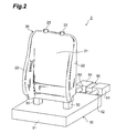
- FIG. 2 is a perspective view showing a manufacturing apparatus for a seat-pad reinforcing cloth according to the first embodiment
- FIG. 3 is a view showing a roughly cut nonwoven fabric sheet or the seat-pad reinforcing cloth before shaped;
- FIG. 4 is a view for explaining the step of fixing the roughly cut nonwoven fabric sheet on a mold
- FIG. 5 is a view for explaining the step of putting a cover member on the mold having the nonwoven fabric sheet fixed thereon;
- FIG. 6 is a view for explaining the step of exhausting air from the closed space defined by the mold and the cover member after covered with the cover member;
- FIG. 7 is a view for explaining the step of supplying heated air (or heated steam) to the internal space of the mold;
- FIG. 8 is a view for explaining the step of shaping the nonwoven fabric sheet into a shape following the outer shape of the mold, by exhausting the air from the closed space defined by the mold and the cover member;
- FIG. 9 is a longitudinal sectional view, as taken along line IX-IX of FIG. 8 , of the seat-pad reinforcing cloth and the mold;
- FIG. 10 is a transverse sectional view, as taken along line X-X of FIG. 8 , of the seat-pad reinforcing cloth and the mold;
- FIG. 11 is a view for explaining the step of demolding the seat-pad reinforcing cloth shaped from the nonwoven fabric sheet, from the mold by removing the cover member;
- FIG. 12 is a perspective view showing a manufacturing apparatus for a seat-pad reinforcing cloth according to the second embodiment
- FIG. 13 is a perspective view showing a manufacturing apparatus for a seat-pad reinforcing cloth according to the third embodiment
- FIG. 14 is a perspective view showing a manufacturing apparatus for a seat-pad reinforcing cloth according to the fourth embodiment
- FIG. 15 is a perspective view showing a movable frame constituting a cover frame of the manufacturing apparatus shown in FIG. 14 ;
- FIG. 16 is a front view where a movable frame is removed from those shown in FIG. 15 ;
- FIG. 17 is a perspective view showing a first modification of a cover member.
- FIG. 18 is a sectional view showing a second modification of a cover member.
- Embodiments of the present invention will be described with reference to the accompanying drawings.
- the embodiments of the invention are exemplified by a reinforcing cloth of a seat pad to be used for the backrest of a vehicular seat
- the present invention can also be applied to the seat portion of the vehicular seat or another portion using a reinforcing cloth of a seat pad.
- FIG. 1 is a perspective view showing one example of the reinforcing cloth of a seat pad, which is manufactured by a method of manufacturing a reinforcing cloth of a seat pad or an apparatus for manufacturing a reinforcing cloth of a seat pad according to the present invention.
- a reinforcing cloth 1 of a seat pad (hereinafter, referred to as a seat-pad reinforcing cloth 1 ) is molded of a roughly cut sheet by a later-described mold 20 , and has a shape corresponding to a sheet for a vehicular seat (not shown).
- the reinforcing cloth 1 includes a back portion 11 corresponding to the surface to confront the back of a user; side portions 12 corresponding to the portions extending toward the user and having shapes to hold the user on the right and left sides; and through holes 13 corresponding to the portions, to which a headrest or the like is attached.
- the molded seat-pad reinforcing cloth 1 is further provided with roundabout portions 14 and 15 .
- the material for the sheet to be molded into the seat-pad reinforcing cloth 1 can be exemplified by a nonwoven fabric, but should not be especially limited, if the material has permeability to the air.
- the sheet made of the nonwoven fabric can be used.
- a sheet having a structure of two or more layers in which the nonwoven fabric sheet is laminated on at least one side of the resin exudation preventing sheet, which is hard for a liquid such as a resin to penetrate.
- the resin exudation prevention means the property, in which resin such as a urethane resin used and molded into the seat pad is hard to penetrate.
- the resin can be prevented from exuding when the seat pad is molded from a urethane resin and the reinforcing layer thereof is formed by a method as of the prior art after the seat-pad reinforcing cloth was molded.
- the material for the low-penetration sheet to be used as the resin exudation preventing sheet can be exemplified by a polyurethane film and a high-density nonwoven fabric of a slow penetration, such as one made of a urethane resin.
- the sheet to be used for molding the seat-pad reinforcing cloth 1 can be exemplified by a sheet, in which a granular thermoplastic resin is contained in a nonwoven fabric, or by a nonwoven fabric sheet, in which low melting point fibers and high melting point fibers are mixed.
- the thermoplastic resin or the low melting point fibers are melted, at the time of heating the nonwoven fabric sheet in the later-described method of the invention, so that the nonwoven fabric sheet is softened to facilitate the molding of the seat-pad reinforcing cloth 1 .
- the seat-pad reinforcing cloth 1 is given a proper rigidity, because it is cooled and solidified after molded, so that the shape of the cloth is kept satisfactory.
- thermoplastic resin In the case of a sheet in which the granular thermoplastic resin is contained in the nonwoven fabric, it is preferred to use a granular hot-melt adhesive resin (or an adhesive) as the thermoplastic resin to be contained.
- This thermoplastic resin can be exemplified by a polyamide resin, a polyester resin, a polyvinyl chloride resin, a polyethylene resin, a polyethylene vinyl acetate resin, a polyurethane resin, a polyvinyl alcohol resin or a polybutyral resin, or mixture thereof.
- the thermoplastic resin is preferred to have a melting point of 70 to 100° C.
- the granular hot-melt adhesive is preferred to have a diameter of 200 ⁇ m or less, and the diameter distribution may be changed, if necessary.
- the following materials can be used.
- the material used for the low melting point fibers has a melting point lower than that of the high melting point fibers. Further, the material used for the low melting point fibers has a specific softening point and a specific molten viscosity.
- the low melting point fibers are specified by the hot-melt type adhesive fibers, which can be melted to fuse the high melting point fibers when they are mixed with the high melting point fibers and heated to a temperature lower than the melting point of the high melting point fibers.
- the fibers to be employed preferably have a thickness of about 1.5 to 10 d (deniers).
- low melting point fibers are exemplified by thermoplastic fibers such as polyester, polyethylene, polypropylene, acryl, nylon, polyvinyl alcohol or polyvinyl chloride. These fibers may be used either solely, or in a conjugate type or a core-sheathed structure by combining them with the high melting point fibers. No specific restriction is exerted on the fineness or length of the low melting point fibers.
- These low melting point fibers are preferred to have a melting point of about 100 to 160° C. (or a softening point of about 80 to 140° C.).
- the low melting point fibers are preferred to have a steam activity, which is proper especially for the case, in which heated steam is used when the nonwoven fabric sheet is heated in the later-described method of the invention.
- Polyester, polypropylene, acryl, nylon or the like is used for the high melting point fibers. No specific restriction is imposed on the fineness and length of the high melting point fibers. These high melting point fibers may have a melting point of 180° C. or higher (or a softening point of 160° C. or higher). Moreover, the difference in the melting point (or in the softening point) between the low melting point fibers and the high melting point fibers is preferred to be 50° C. or more.
- the mixing percentage of the low melting point fibers and the high melting point fibers is preferable at 20 to 70 weight % for the low melting point fibers and at 30 to 80 weight % for the high melting point fibers. If the mixing percentage of the low melting point fibers is 20 weight % or less, the fused portion may become less for the desired rigidity. If the mixing percentage of the low melting point fibers is 70 weight % or more, the rigidity appears so prominent as to make the demolding from the mold difficult. In addition, the surface of the molded sheet is plasticized to leave no fiber so that rubbing noises are easily made when the sheet is used as the seat-pad reinforcing cloth.
- a “nonwoven fabric sheet” means a sheet using a nonwoven fabric for molding the seat-pad reinforcing cloth 1 .
- a nonwoven fabric sheet before molded will be described as the “nonwoven fabric sheet”
- a nonwoven fabric sheet after molded will be described as a “seat-pad reinforcing cloth”.
- FIGS. 2 , 5 , 9 and 10 an apparatus according to the present invention for manufacturing the seat-pad reinforcing cloth (the reinforcing cloth of a seat pad) will be described with reference to FIGS. 2 , 5 , 9 and 10 .
- FIG. 2 is a perspective view showing an apparatus 2 for manufacturing the seat-pad reinforcing cloth.
- the manufacturing apparatus 2 includes a mold 20 ; a base portion 30 on which the mold 20 is fixed; a cover member 40 (as referred to FIG. 5 and so on) fixed on the base portion 30 while covering the mold 20 for forming a closed space 41 ; and an air supply/exhaust unit 50 for supplying air to the closed space 41 and exhausting air from the closed space 41 .
- the mold 20 has an outer shape formed into a substantially identical shape as that of the seat-pad reinforcing cloth 1 , and has an internal space 26 (as referred to FIGS. 9 and 10 ) therein.
- the mold 20 includes a front surface portion 21 , side surface portions 22 , cylindrical portions 23 , a rear surface portion 24 (as referred to FIGS. 9 and 10 ), and a plurality of air holes 25 (as referred to FIGS. 9 and 10 ).
- the front surface portion 21 of the mold 20 provides a portion for molding the back portion 11 of the seat-pad reinforcing cloth 1
- the side surface portions 22 provide portions for molding the side portions 12 and the roundabout portions 15 (as referred to FIG.
- the cylindrical portions 23 of the mold 20 provide portions for molding the peripheries of the through holes 13 of the seat-pad reinforcing cloth 1
- the rear surface portion 24 provides a portion for molding the roundabout portion 14 (as referred to FIG. 9 ) of the seat-pad reinforcing cloth 1 .
- the air holes 25 are formed to provide interconnection from the outer surface of the mold 20 to the internal space 26 , and act as air passages when the air is supplied to the closed space 41 and exhausted from the closed space 41 by the air supply/exhaust unit 50 .
- the air holes 25 are formed in each of the front surface portion 21 , the side surface portions 22 , the cylindrical portions 23 and the rear surface portion 24 .
- the material for the mold 20 is not especially limited, it is preferably exemplified by aluminum for the aspects of workability and thermal conductivity.
- the base portion 30 includes a base 31 , an air-supply leg 32 and an air-exhaust leg 33 . Both the air-supply leg 32 and the air-exhaust leg 33 are erected from the base 31 and attached to the mold 20 .
- the air-supply leg 32 and the air-exhaust leg 33 are made hollow and connected to the internal space 26 of the mold 20 so that they provide air passages connecting the closed space 41 and the air supply/exhaust unit 50 , together with the air supply/exhaust passages (not shown) in the base 31 .
- the cover member 40 is not restricted in specific shape and size, so long as the cover member 40 can cover the mold 20 having a nonwoven fabric fixed thereon, but is preferably exemplified by a bag-shaped film for easy handling. Though, in FIG. 5 , the cover member 40 is fixed with respect to the base 31 , it is sufficient that the cover member 40 is fixed to form the closed space 41 for covering a nonwoven fabric sheet 1 B, which will become the seat-pad reinforcing cloth 1 after molded. Accordingly, the cover member 40 may also be fixed on the air-supply leg 32 and the air-exhaust leg 33 .
- the cover member 40 is heated and is repeatedly made inflated and closely contacted with the nonwoven fabric sheet 1 B and the mold 20 by the air supply/exhaust of the air supply/exhaust unit 50 . Therefore, the material for the cover member 40 is selected to have properties for satisfying these points.
- the seat-pad reinforcing cloth to be used for the backrest of the vehicular seat is preferred to have an elongation of 300% or more and a thickness of about 30 to 100 ⁇ m when molded.
- the elongation of the cover material may be lower than 300%.
- the material for the cover member 40 (of the bag-shaped film) can be exemplified by polyurethane of an elongation of 300% and a thickness of 50 ⁇ m.
- the air supply/exhaust unit 50 includes an air-supply unit 51 (heating unit); an air-supply tube 52 for connecting the air-supply unit 51 and the air-supply passage in the base portion 30 ; an air-exhaust unit 54 ; and an air-exhaust tube 53 for connecting the air-exhaust unit 54 and the air-exhaust passage in the base portion 30 .
- the air-supply unit 51 (heating unit) is enabled to heat the mold 20 and the nonwoven fabric sheet 1 B by supplying the heated air to the internal space 26 of the mold 20 through the air-supply passage and the air-supply leg 32 in the base 31 .
- the heated air is supplied to the closed space 41 through the internal space 26 of the mold 20 and through the air holes 25 so that the cover member 40 is inflated according to the supply of the heated air.
- this heated air includes not only the merely heated air but also heated steam.
- the time period for the nonwoven fabric sheet 1 B to be melted and solidified can be shortened (especially, in case the nonwoven fabric sheet 1 B is made of a sheet, in which a granular thermoplastic resin is contained in a nonwoven fabric, or a sheet, in which low melting point fibers and high melting point fibers are mixed). That is, the time period for molding the reinforcing cloth can be shortened.
- the air-exhaust unit 54 is not specifically restricted, if it is a device capable of exhausting the air of the closed space 41 through the air holes 25 , the internal space 26 of the mold 20 , the air-exhaust leg 33 , the air-exhaust passage (not shown) in the base portion 30 , and the air-exhaust tube 53 .
- molds having corresponding convex and concave surfaces are not required because no press molding is done.
- any special mold such as a slide core mold is not required for the molding of the roundabout portions 14 and 15 having the complicated shapes, as shown in FIG. 8 and FIG. 9 . It is, therefore, possible to spare the cost and the time period for manufacturing the mold.
- heated air is supplied to the closed space through a pathway different from that of the first embodiment.
- heated air is supplied to a closed space 41 without going through an internal space 26 on a mold 20 .
- heated air is supplied to the internal space 26 of the mold 20 via an air-supply leg 32
- heated air is supplied to the closed space 41 via an air supply tube 52 , an air-supply path (not shown) in the base portion 130 , and an air-supply holes 135 . Therefore, a leg 132 acts to fix the mold 20 to the base 131 , but is structured not to connect an air-supply path in the base portion 130 with the internal space 26 of the mold 20 .
- the manufacturing apparatus according to the third embodiment is different from the manufacturing apparatus according to the first embodiment in that a closed space is formed in such a manner that a cover member covers a sheet fixed to a mold from front and back, and from sides, using a cover frame to which a cover member is fixed.
- a closed space is formed in such that a cover member covers entire sheet fixed to a mold without any member such as the cover frame.
- FIG. 13 is a perspective view showing an apparatus 202 for manufacturing the seat-pad reinforcing cloth according to the third embodiment.
- the manufacturing apparatus 202 includes a mold 20 ; a base portion 230 to which the mold 20 is fixed; a cover member 240 which forms a closed space 241 by covering a sheet fixed to the mold 20 from front and back, and from sides; and a cover frame 260 being formed so as to enclose the mold 20 and to which the cover member 240 is fixed. Further, as with the case of the manufacturing apparatus 2 according to the first embodiment, the manufacturing apparatus 202 includes an air supply/exhaust unit 50 for supplying air to the closed space 241 and exhausting air from the closed space 241 . In addition, the manufacturing apparatus 202 shown in FIG. 13 is able to manufacture two seat-pad reinforcing cloths at once by providing two molds 20 in the interior of the closed space 241 .
- the base portion 230 includes a base 231 , a leg 234 for supporting the base 231 , and an air-supply leg 32 and an air-exhaust leg 33 standingly provided from the base 231 and mounted independently to the mold 20 .
- the air-supply leg 32 and the air-exhaust leg 33 of the base portion 230 after being interconnected with the internal space 26 of the mold 20 , constitute an air flow channel connecting the closed space 241 and the air supply/exhaust unit 50 , together with the air-supply path and the air-exhaust path provided inside of the base 231 .
- the cover member 240 is a film in sheet-shape and can be the same material as used, for a cover member 40 of the manufacturing apparatus 2 according to the first embodiment.
- the cover member 240 is fixed to the cover frame 260 so as to cover a sheet fixed to the mold 20 from front and back, and from sides, and forms the closed space 241 together with the cover frame 260 and the base portion 230 .
- the cover member 240 is fixed to an end part of the cover frame 260 (specifically, a movable frame 261 and a top panel 262 , which will be described later), but not fixed to the base portion 230 .
- the air-supply/exhaust unit 50 is similar to the air-supply/exhaust unit used in the manufacturing apparatus 2 according to the first embodiment and is capable of heating the mold 20 and a non-woven fabric sheet 1 B by supplying heated air to the internal space 26 of the mold 20 via the air-supply leg 32 or the like. Further, the air-supply/exhaust unit 50 can exhaust air in the closed space 241 via the air-exhaust leg 33 or the like.
- the cover frame 260 includes the movable frame 261 , the top panel 262 disposed opposing to the movable frame 261 , and stanchions 263 at one end part of which are fixed against the top panel 262 and the other end part of which are fixed to the leg 234 .
- the movable frame 261 includes a penetration portion 261 A through which the stanchion 263 penetrates, and is disposed so that it can move upwards and downwards along four stanchions 263 .
- the aforementioned cover member 240 is disposed between the movable frame 261 and the top panel 262 and is fixed so that air inflow/outflow with respect to the closed space 241 may not occur at end parts of the movable frame 261 and the top panel 262 . With this construction, a sufficient space is secured for a worker to fix the non-woven fabric sheet 1 B to the mold 20 under such a state where the movable frame 261 is elevated to a position close to the top panel 262 (in FIG.
- movable frame 261 shown by chain double-dashed lines movable frame 261 shown by chain double-dashed lines
- the closed space 241 is formed under such a state where the movable frame 261 is lowered to a position where it makes contact with a base 231 (in FIG. 13 , the movable frame 261 shown by solid lines).
- a packing, an adhesive tape or the like is disposed on an end face 261 E where the movable frame 261 and the base 231 contact each other in consideration of prevention of air inflow/outflow with respect to the closed space 241 via the end face 261 E.
- the closed space 241 is formed by a movement of the movable frame 261 of the cover frame 260 . Therefore, since it is possible to form the closed space 241 by a movement of the movable frame 261 that is a part of the cover frame 260 , not only the closed space 241 can be formed with ease, but also a time required for forming can be shortened. Especially, in a case where the movable frame 261 is configured to be capable of being driven by a driving apparatus, a series of manufacturing steps by the manufacturing apparatus can be automated with ease.
- FIGS. 14 to 16 a fourth embodiment of the apparatus for manufacturing the reinforcing cloth of seat pad according to the present invention will be described.
- the manufacturing apparatus according to the fourth embodiment is identical with the manufacturing apparatus 202 according to the third embodiment in that the cover frame, to which the cover member is fixed, is provided, a difference is that the cover frame moves in a horizontal direction. Further, it is different from the manufacturing apparatus 202 according to the third embodiment in that the inside and the outside of the closed space are interconnected via a duct provided to the cover frame.
- FIG. 14 is a perspective view showing an apparatus 302 for manufacturing a seat-pad reinforcing cloth according to the fourth embodiment.
- FIG. 15 is a perspective view showing movable frames 361 A and 361 B constituting a cover frame 360 of the manufacturing apparatus 302 .
- the apparatus 302 for manufacturing the seat-pad reinforcing cloth includes a mold 20 , a base portion 330 to which the mold 20 is fixed, a cover member 340 which forms a closed space 341 by covering the mold 20 from front and back, and the cover frame 360 which is formed so as to enclose the mold 20 and to which the cover member 340 is fixed. Further, as with the case of the manufacturing apparatus according to the first embodiment, the manufacturing apparatus 302 includes an air supply/exhaust unit 50 for supplying air to the closed space 341 and exhausting air from the closed 341 . Furthermore, as with the case of the manufacturing apparatus according to the third embodiment, the apparatus 302 for manufacturing the seat-pad reinforcing cloth shown in FIG. 14 is capable of manufacturing two seat-pad reinforcing cloths at once by providing two molds 20 in the interior of the closed space 341 .
- a base portion 330 includes a base 331 , a leg 334 for supporting the base 331 , and an air-supply leg 32 and an air-exhaust leg 33 standingly provided from the base 331 and mounted independently to the mold 20 .
- the air-supply leg 32 and the air-exhaust leg 33 of the base portion 330 after being interconnected with the internal space 26 of the mold 20 , constitute an air flow channel connecting the closed space 341 and the air supply/exhaust unit 50 , together with the air-supply path and the air-exhaust path provided inside of the base 331 .
- the closed space 341 is formed by the cover member 340 , the cover frame 360 , the air-supply leg 32 and the air-exhaust leg 33 of the base portion 330 , while the base 331 is not involved directly with formation of the closed space 341 .
- the cover member 340 is a film in sheet-shape and can be the similar material to that used for the cover member 40 of the manufacturing apparatus 2 according to the first embodiment.
- This cover member 340 is fixed to the cover frame 360 so as to cover from front and back the mold 20 , and forms the closed space 341 .
- the cover member 340 is fixed only to an end part of the cover frame 360 (specifically, movable frames 361 A and 361 B which will be described later).
- the air-supply/exhaust unit 50 is similar to the air-supply/exhaust unit used in the manufacturing apparatus 2 according to the first embodiment and is capable of heating the mold 20 and the non-woven fabric sheet 1 B by supplying heated air to the internal space 26 of the mold 20 via the air-supply leg 32 or the like. Further, the air-supply/exhaust unit 50 can exhaust air in the closed space 341 via the air-exhaust leg 33 or the like.
- the cover frame 360 includes two movable frames 361 A and 361 B, a top panel 362 disposed at upper portion of the movable frames 361 A and 361 B, stanchions 363 for fixing the top panel 362 against a leg 334 , an actuator 364 for moving the movable frames 361 A and 361 B in the horizontal direction, and a duct 365 for interconnecting the inside and the outside of the closed space 341 .
- the movable frames 361 A and 361 B are a pair of movable frames capable of being separated in the horizontal direction, and are disposed so as to be moveable in the horizontal direction by driving of the actuator 364 (a direction in parallel with a surface of the base 331 and of the top panel 362 ).
- the aforementioned cover member 340 is fixed so as to cover the mold 20 from front and back, so that air inflow/outflow with regard to the closed space 341 may not occur at each end part of the movable frames 361 A and 361 B. With this construction, a sufficient space is secured for a worker to fix the non-woven fabric sheet 1 B to the mold 20 under such a state where the movable frames 361 A and 361 B are spaced.
- the closed space 341 is formed under such a state where the movable frames 361 A and 361 B are in contact at an end face 361 B (states as shown in FIGS. 14 and 15 ). Further, a packing, an adhesive tape or the like is disposed on an end face 361 E where the movable frames 361 A and 361 B are in contact in consideration of prevention of air inflow/outflow with respect to the closed space 341 via the end face 361 E.
- the duct 365 of the movable frames 361 A and 361 B is led to outside of the movable frames 361 A and 361 B via inside of the movable frames 361 A and 361 B (not shown) and is disposed so that the inside and the outside of the closed space 341 are interconnected via a plurality of openings 365 A provided on a surface of the movable frames 361 A and 361 B (see FIG. 15 ).
- the duct 365 is independently connected to the air-supply/exhaust unit 50 via a suction/exhaust tube (not shown) and is constituted to allow supplying of heated air and exhausting of air from the closed space 341 by the air-supply/exhaust unit 50 .
- FIG. 16 is a front view where the movable frame 361 B is removed in FIG. 15 and shows positional relationship of the movable frame 361 A and the base portion 330 .
- the closed space 341 is formed by the cover member 340 , the cover frame 360 , and the air-supply leg 32 and the air-exhaust leg 33 of the base portion 330 . Therefore, as shown in FIG.
- a packing, an adhesive tape or the like is disposed on the end face 361 F where the air-supply leg 32 and the air-exhaust leg 33 are in contact with the movable frames 361 A and 361 B in consideration of prevention of air inflow/outflow with respect to the closed space 341 via the end face 361 F.
- the closed space 341 is formed by a movement of the movable frames 361 A and 361 B of the cover frame 360 . Therefore, since a closed space is formed with ease by a movement of the movable frames 361 A and 361 B, compared with a case where the mold is covered using a cover member of bag-shape film, a time required for forming a closed space and a time for securing a space for demolding of the sheet after processing from the mold can be shortened. Further, since the movable frame 361 can be moved by the actuator 364 , a series of manufacturing steps by the manufacturing apparatus can be automated with ease.
- the manufacturing apparatus 302 according to the fourth embodiment is constituted so that the inside and the outside of the closed space 341 are interconnected via the duct 365 of the movable frames 361 A and 361 B. Therefore, supplying of heated air and exhausting of air from the closed space 341 by the air-supply/exhaust unit 50 can be carried out via not only the internal space 26 of the mold 20 , but also the duct 365 . Therefore, since the number of supply/exhaust ports is increased as a whole apparatus, a time required for supplying of heated air and exhausting of air can be shortened.
- FIG. 17 is a perspective view showing a first modification of a cover member.
- a cover member 440 according to a first modification has a plurality of pleat portions 441 in a state before air in the closed space is exhausted.
- the existence of the pleat portions 441 is the difference from the cover member 40 using aforementioned bag-shaped film or the cover members 240 and 340 using a film in sheet-shape.
- pleats referred to here denotes a loosely overlapped portion or an allowance such as a drape of a curtain caused when a cloth is hung down.
- the pleat portion 441 may be disposed so that a plurality of pleats is arranged regularly successively or irregularly successively.
- An elastic cord 442 is fixed onto a surface of the cover member 440 so as to maintain shapes of the pleat portions 441 .
- This elastic cord 442 is fixed to the cover member 440 by sewing, bonding or the like so as to intersect the pleat portion 441 .
- a rubber cord may be used as the elastic cord 442 .
- the cover member 440 When the cover member 440 according to the modification is used in place of the cover members 40 , 240 and 340 , the pleat portion 441 acts as an elongation margin while the non-woven fabric sheet 1 B is processed to a shape along an outer shape of the mold 20 . Therefore, the cover member 440 can exhibit higher shape followability for a mold 20 having a complex shape or a large roundabout portion.
- the elastic cord 442 being fixed so as to maintain a shape of the pleat portion 441 , when air is exhausted from the closed spaces 41 , 241 and 341 in a step of processing the non-woven fabric sheet 1 B along the outer shape of the mold 20 , a large deformation to cope with approximate shape (outline shape) of the mold 20 can be followed by a deformation of the elastic cord 442 , and a small deformation to cope with details of the mold 20 can be followed by a deformation of the pleat portion 441 .
- cover member 440 is greatly deformed to follow an approximate shape of the mold (e.g., initial stage of exhausting), pleat portions 441 are prevented from being one-sided to specific portion of the mold 20 and therefore, the cover member 440 can exhibit higher shape followability for the mold 20 having a complex shape or a large roundabout portion.
- the elastic cord 442 is fixed to the cover member 440 so as to intersect the pleat portion 441 .
- the cover member 440 having aforementioned features can cope with a large elongation and therefore, may be used preferably as a cover member to be mounted to the movable frame 261 in the third embodiment and the movable frames 361 A and 361 B in the fourth embodiment.
- the pleat portion 441 is formed in a horizontal direction
- a direction of forming the pleat portion 441 is not restricted to this exemplification and may be formed in vertical direction only or in both horizontal and vertical directions.
- a gravitational force resulting in a collapse of the shape is not exerted and therefore, the pleat portion can maintain the shape even if an elastic cord is not provided for the vertical pleats.
- FIG. 18 is a sectional view showing a second modification of a cover member.
- a cover member 540 according to the second modification is different from other cover members 40 , 240 , 340 and 440 in that it has a double-layer structure.
- the cover member 540 includes a main layer 541 with air-tightness and a reinforcing layer 542 with tensile strength higher than that of the main layer.
- materials constituting each layer for the main layer 541 , for example, a urethane film with air-tightness may be used.
- expandable raw materials in knit form i.e., raw materials with knitted stitch
- the reinforcing layer 542 for example, jersey texture or cotton sheeting made of nylon, polyester, acrylic or the like, may be used.
- bonding is preferably used for lamination while the main layer 541 may be coated with respect to the reinforcing layer 542 .
- the main layer 541 is disposed so as to form outside with respect to the closed spaces 41 , 241 , 341 and 441 while the reinforcing layer 542 is disposed on a surface of the main layer 541 at a side where the cover member 540 makes contact with the mold 20 (a side facing with closed spaces 41 , 241 , 341 and 441 ) and is fixed to the base portion 30 or the movable frames 261 , 361 A, 361 B or the like.
- the cover member 540 according to the modification includes the main layer 541 with air-tightness and the reinforcing layer 542 with tensile strength higher than that of the main layer, damage to the main layer 541 attributable to an elongation caused at processing can be suppressed by the reinforcing layer 542 , even in a case where thin and expandable raw materials are used for the main layer 541 . Therefore, durability against repeated use of cover members is improved.
- the reinforcing layer 542 of the cover member 540 is disposed on a side contacting with the mold 20 and expandable raw materials in knit form are used, the reinforcing layer 542 with raw materials in knit form acts as a buffer layer against the main layer 541 when air in the closed space is exhausted and the reinforcing layer 542 comes to contact with the mold 20 . Therefore, durability against repeated use of the cover member 540 is improved.
- FIGS. 3 to 11 the method for manufacturing a seat-pad reinforcing cloth according to the present invention will be described.
- a case of manufacturing a seat-pad reinforcing cloth 1 using the manufacturing apparatus according to the first embodiment is given.
- the nonwoven fabric sheet 1 B (i.e., the seat-pad reinforcing cloth 1 before molded) to be used in the present invention is supplied after roughly cut in the shape of the vehicular seat-pad reinforcing cloth to be used.
- the nonwoven fabric sheet 1 B is thus cut to eliminate such troubles of cutting off the unnecessary portions as might be caused after the seat-pad reinforcing cloth was molded.
- the nonwoven fabric sheet 1 B thus cut is put on the mold 20 , as shown in FIG. 4 , and is then fixed by magnets (not shown). These magnets have been attached in advance to the inner surface of the mold, and the nonwoven fabric sheet 1 B is fixed by placing other magnets on the nonwoven fabric sheet 1 B put on the mold 20 . Alternatively, magnets or iron screws are buried in the mold 20 , and the nonwoven fabric sheet 1 B may be fixed by using magnets as members for holding the same. The nonwoven fabric sheet 1 B is thus fixed so that it can be prevented from coming out when the heated air is supplied and exhausted by the air supply/exhaust unit 50 . For an illustrative purpose, the nonwoven fabric sheet 1 B is made transparent in FIG. 4 .
- the nonwoven fabric sheet 1 B is covered with the cover member 40 after the nonwoven fabric sheet 1 B is fixed on the mold 20 , as shown in FIG. 5 , thereby to form the closed space 41 between the mold 20 and the cover member 40 .
- a preliminary air exhaust may be preferably executed to exhaust the air from the closed space 41 through the air holes 25 of the mold 20 .
- the nonwoven fabric sheet 1 B can be brought into close contact with the mold 20 by the cover member 40 , so that the nonwoven fabric sheet 1 B can be easily molded according to the shape of the outer surface of the mold 20 .
- the heated air (including the heated steam) is then supplied to the inside of the mold 20 from the air-supply unit 51 (heating unit) of the air supply/exhaust unit 50 , as shown in FIG. 7 , to heat the nonwoven fabric sheet 1 B and the mold 20 .
- the heated air is supplied to the closed space 41 through the air holes 25 of the mold 20 so that the cover member 40 is inflated.
- the nonwoven fabric sheet 1 B can be heated by both the heated air and the heat from the mold, so that the supplied air is effectively utilized for heating the nonwoven fabric sheet 1 B.
- the heated air is directly supplied to the closed space 41 so that it can heat the nonwoven fabric sheet 1 B like the case of using the manufacturing apparatus 2 .
- the manufacturing apparatus 102 does not take the mode, in which the heated air is supplied to the closed space 41 from the internal space 26 of the mold 20 through the air holes 25 .
- the temperature of the heated air is set to a level higher than the melting point of the low melting point fibers but lower than the melting point of the high melting point fibers.
- Low melting point fibers polyester: EE-7 [produced by UNITIKA FIBERS LTD.]: a fiber length of 41 mm, a fiber thickness of 6 d (deniers), a melting point of 110° C. (or a softening point of 90° C.), and a mixing percentage of 40 weight %
- High melting point fibers polyester: C300 Tetoron (Registered Trade Mark) [produced by TORAY INDUSTRIES, INC.]: a fiber length of 64 mm, a fiber thickness of 6 d (deniers), a melting point of 200° C. (or a softening point of 180° C.), and a mixing percentage of 60 weight %
- Weight per unit area of the nonwoven fabric sheet 1 B 120 g/m 2
- the air-exhaust unit 54 is activated to exhaust the air in the closed space 41 , as shown in FIG. 8 .
- the air in the closed space 41 flows into the mold 20 through the nonwoven fabric sheet 1 B having an air permeability and the air holes 25 of the mold 20 , as shown in FIGS. 9 and 10 .
- the inside of the mold 20 interconnects with the air-exhaust unit 54 through the air-exhaust leg 33 , the air-exhaust passage of the base 31 and the air-exhaust pipe 53 , the air in the closed space 41 can be exhausted.
- the inflated cover member 40 is deflated to be sucked by the mold 20 .
- the nonwoven fabric sheet 1 B having been heated to a high plasticity is deformed to be sucked by the mold 20 .
- the nonwoven fabric sheet 1 B comes into close contact with the mold 20 so that it is shaped into a shape following the outer shape of the mold 20 .
- the air in the closed space 41 is exhausted while the thermoplastic resin being heated and melted, so that the nonwoven fabric sheet 1 B is brought into close contact with the mold 20 . After brought into close contact, the nonwoven fabric sheet 1 B is cooled, and the thermoplastic resin is solidified.
- the nonwoven fabric sheet 1 B can not only take a shape following the outer shape of the mold 20 but also have a proper rigidity to the seat-pad reinforcing cloth 1 after molded.
- the air in the closed space 41 is exhausted while the low melting point fibers are heated and melted, and the nonwoven fabric sheet 1 B is brought into close contact with the mold 20 . Then, while the nonwoven fabric sheet 1 B is cooled after brought into close contact, the low melting point fibers are solidified on the high melting point fibers in the nonwoven fabric sheet 1 B.
- the nonwoven fabric sheet 1 B can not only take a shape following the outer shape of the mold 20 but also have a proper rigidity to the seat-pad reinforcing cloth 1 after molded.
- the cover member 40 is removed, and the molded nonwoven fabric sheet 1 B (i.e., the seat-pad reinforcing cloth 1 ) is demolded from the mold 20 .
- the cooled nonwoven fabric sheet 1 B retains some rigidity, which does not obstruct demolding from the mold 20 , so that the nonwoven fabric sheet 1 B can be easily demolded.
- the reinforcing cloth of the seat pad is manufactured using the manufacturing apparatus 202 according to the third embodiment shown in FIG. 13 , it is possible to manufacture the seat-pad reinforcing cloth 1 by performing the same procedures as used for the manufacturing apparatus 2 according to the aforementioned first embodiment, except that the closed space 241 is formed by a movement of the movable frame 261 of the cover frame 260 .
- the reinforcing cloth of the sheet pad is manufactured using the manufacturing apparatus 302 according to the fourth embodiment shown in FIG. 14 , it is possible to manufacture the seat-pad reinforcing cloth 1 by performing the same procedures as used for the manufacturing apparatus 2 according to the aforementioned first embodiment, except that the closed space 341 is formed by a movement of the movable frames 361 A and 3618 of the cover frame 360 , and supplying of heated air and exhausting of air are performed using the duct 365 .
- the closed space 241 ( 341 ) is formed by at least the mold 20 , the cover member 240 ( 340 ) and the cover frame 260 ( 360 ) which is formed so as to enclose the mold 20 and to which the cover member 240 ( 340 ) is fixed.
- the base 231 of the base portion 230 contributes to formation of the closed space 241
- the air-supply leg 32 and the air-exhaust leg 33 of the base portion 330 contribute to formation of the closed space 341 .
- the sheet is molded by fixing it on the mold, which is given a shape substantially identical to that of the seat pad, so that the molded sheet takes substantially the same shape as that of the desired seat-pad reinforcing cloth.
- the mold which is given a shape substantially identical to that of the seat pad, so that the molded sheet takes substantially the same shape as that of the desired seat-pad reinforcing cloth.
- the non-woven fabric sheet 1 B is heated utilizing heated air in the apparatuses 2 , 102 , 202 and 302 for manufacturing the seat-pad reinforcing cloth according to the aforementioned embodiments
- the non-woven fabric sheet 1 B may be heated by heating the mold 20 itself using a heater or the like.
- the manufacturing apparatus 202 according to the third embodiment may be constituted in such that heated air is supplied to the closed space 41 via the air-supply path provided inside the base portion 130 and a plurality of air supply holes disposed to the base 231 , while using the similar structure to that used for the base portion 130 in the manufacturing apparatus 102 according to the second embodiment.
- cover member 440 shown in FIG. 17 may be combined with the cover member having double-layer structure as shown in FIG. 18 .
Abstract
Description
Claims (14)
Priority Applications (1)
| Application Number | Priority Date | Filing Date | Title |
|---|---|---|---|
| US12/370,678 US8926309B2 (en) | 2005-03-07 | 2009-02-13 | Method of manufacturing reinforcing cloth of a seat pad and apparatus therefor |
Applications Claiming Priority (4)
| Application Number | Priority Date | Filing Date | Title |
|---|---|---|---|
| JP2005062894 | 2005-03-07 | ||
| JPP2005-062894 | 2005-03-07 | ||
| JPP2006-031487 | 2006-02-08 | ||
| JP2006031487A JP4503538B2 (en) | 2005-03-07 | 2006-02-08 | Manufacturing method and manufacturing apparatus for seat pad reinforcing cloth |
Related Child Applications (1)
| Application Number | Title | Priority Date | Filing Date |
|---|---|---|---|
| US12/370,678 Division US8926309B2 (en) | 2005-03-07 | 2009-02-13 | Method of manufacturing reinforcing cloth of a seat pad and apparatus therefor |
Publications (2)
| Publication Number | Publication Date |
|---|---|
| US20060197250A1 US20060197250A1 (en) | 2006-09-07 |
| US7758802B2 true US7758802B2 (en) | 2010-07-20 |
Family
ID=36943383
Family Applications (2)
| Application Number | Title | Priority Date | Filing Date |
|---|---|---|---|
| US11/367,606 Active 2028-09-20 US7758802B2 (en) | 2005-03-07 | 2006-03-04 | Method of manufacturing reinforcing cloth of sheet pad and apparatus therefor |
| US12/370,678 Active 2026-08-24 US8926309B2 (en) | 2005-03-07 | 2009-02-13 | Method of manufacturing reinforcing cloth of a seat pad and apparatus therefor |
Family Applications After (1)
| Application Number | Title | Priority Date | Filing Date |
|---|---|---|---|
| US12/370,678 Active 2026-08-24 US8926309B2 (en) | 2005-03-07 | 2009-02-13 | Method of manufacturing reinforcing cloth of a seat pad and apparatus therefor |
Country Status (2)
| Country | Link |
|---|---|
| US (2) | US7758802B2 (en) |
| JP (1) | JP4503538B2 (en) |
Families Citing this family (10)
| Publication number | Priority date | Publication date | Assignee | Title |
|---|---|---|---|---|
| CN101573444B (en) | 2006-10-16 | 2013-02-13 | 花王株式会社 | Lytic enzyme inhibitor, lysis inhibitor, inhibitor of degradation of poly-gamma-glutamic acid, and method for production of poly-gamma-glutamic acid |
| JP5133100B2 (en) * | 2008-03-17 | 2013-01-30 | 豊田通商株式会社 | Seat pad reinforcing cloth manufacturing method, manufacturing apparatus, and seat pad reinforcing cloth |
| JP5665630B2 (en) * | 2011-03-31 | 2015-02-04 | 三菱重工業株式会社 | Method and apparatus for molding composite hollow parts |
| CN103781955B (en) | 2012-05-22 | 2016-05-25 | 三井化学株式会社 | Nonwoven fabric laminate for expansion molding, the carbamate foaming nanocrystal composition that uses this layered nonwoven fabric and the manufacture method of nonwoven fabric laminate for expansion molding |
| FR3007317B1 (en) * | 2013-06-25 | 2015-10-23 | Salomon Sas | METHOD FOR MANUFACTURING A HOLLOW OBJECT |
| CN105518196B (en) | 2013-09-06 | 2017-02-08 | 三井化学株式会社 | Nonwoven fabric laminate for foaming molding, method for producing nonwoven fabric laminate for foaming molding, urethane foaming molding composite, vehicle seat, and chair |
| JP6651732B2 (en) * | 2015-08-12 | 2020-02-19 | 東洋紡株式会社 | Foam molding method |
| DE102016109924A1 (en) * | 2016-05-30 | 2017-11-30 | Ford-Werke Gmbh | Seat back trim and method of making same |
| WO2023218722A1 (en) * | 2022-05-11 | 2023-11-16 | 株式会社型技術事務所モート | Method and apparatus for producing seat pad reinforcing cloth, and molding die |
| JP7252586B1 (en) | 2022-05-13 | 2023-04-05 | 東洋インキScホールディングス株式会社 | Hot-melt magnetic tape, cloth-like material for foam molding and method for producing the same, method for producing foam-molded composite, and vehicle seat |
Citations (20)
| Publication number | Priority date | Publication date | Assignee | Title |
|---|---|---|---|---|
| US2392108A (en) | 1943-02-20 | 1946-01-01 | Vidal Corp | Apparatus for molding laminated structures |
| US3134148A (en) | 1961-08-10 | 1964-05-26 | Taccone Corp | Multiple layer diaphragm and molding machine in combination therewith |
| JPS5270176A (en) | 1975-12-05 | 1977-06-10 | Hiroyuki Kanai | Unwoven fabric for hybrid molding |
| US4323410A (en) * | 1979-10-31 | 1982-04-06 | Tachikawa Spring Co., Ltd. | Method of manufacturing seat cushions |
| JPS62162060A (en) | 1985-12-30 | 1987-07-17 | ダイニツク株式会社 | Sheet like molding material |
| US4702376A (en) * | 1986-10-03 | 1987-10-27 | Fairprene Industrial Products Company, Inc. | Composite vacuum bag material having breather surface |
| JPH0261153A (en) | 1988-08-25 | 1990-03-01 | Toyobo Co Ltd | Nonwoven fabric and production thereof |
| US5000805A (en) * | 1989-04-28 | 1991-03-19 | Hoover Universal, Inc. | Method for vacuum forming composite vehicle seat |
| JPH04105921A (en) | 1990-08-27 | 1992-04-07 | Nissan Altia Co Ltd | Manufacture of seat cover |
| US5123985A (en) | 1986-09-02 | 1992-06-23 | Patricia Evans | Vacuum bagging apparatus and method including a thermoplastic elastomer film vacuum bag |
| US5190809A (en) * | 1989-08-31 | 1993-03-02 | Stamicarbon B.V. | Fabric of thermoplastic fiber and continuous reinforcing fiber |
| JPH05130923A (en) | 1991-11-11 | 1993-05-28 | Toyota Tsusho Kk | Molded reinforcing cloth for cushion material |
| JPH05138782A (en) | 1991-11-22 | 1993-06-08 | Bridgestone Corp | Sheet for vehicles |
| JPH05220830A (en) | 1992-02-08 | 1993-08-31 | Meiwa Ind Co Ltd | Method for rolling skin material on rear face of core material |
| US5328540A (en) | 1992-03-06 | 1994-07-12 | Northrop Corporation | Mechanized lay up assembly line for composite structures |
| JPH10291267A (en) | 1998-03-20 | 1998-11-04 | Watahoshi Sangyo Kk | Manufacture of fiber-made cushion material |
| JP2000062061A (en) | 1998-08-26 | 2000-02-29 | Asahi Chem Ind Co Ltd | Reinforcing material base fabric for foam molding |
| US6120630A (en) * | 1995-11-13 | 2000-09-19 | Milsco Manufacturing Company | Method of making a seat cushion |
| US6257866B1 (en) | 1996-06-18 | 2001-07-10 | Hy-Tech Forming Systems, Inc. | Apparatus for accurately forming plastic sheet |
| JP2005028626A (en) | 2003-07-08 | 2005-02-03 | Yoshimura Kasei Kk | Method and apparatus for molding resin sheet |
Family Cites Families (4)
| Publication number | Priority date | Publication date | Assignee | Title |
|---|---|---|---|---|
| US4692199A (en) * | 1985-12-13 | 1987-09-08 | Lear Siegler, Inc. | Method and apparatus for bonding fabric to a foam pad |
| US4718153A (en) * | 1986-04-10 | 1988-01-12 | Steelcase Inc. | Cushion manufacturing process |
| US4744848A (en) * | 1987-02-02 | 1988-05-17 | Rhj Products, Inc. | Method of forming a contoured shape |
| US5679197A (en) * | 1995-07-27 | 1997-10-21 | Hoover Universal, Inc. | Method for bonding a cover fabric to a cushion body using a pressurized environment |
-
2006
- 2006-02-08 JP JP2006031487A patent/JP4503538B2/en active Active
- 2006-03-04 US US11/367,606 patent/US7758802B2/en active Active
-
2009
- 2009-02-13 US US12/370,678 patent/US8926309B2/en active Active
Patent Citations (20)
| Publication number | Priority date | Publication date | Assignee | Title |
|---|---|---|---|---|
| US2392108A (en) | 1943-02-20 | 1946-01-01 | Vidal Corp | Apparatus for molding laminated structures |
| US3134148A (en) | 1961-08-10 | 1964-05-26 | Taccone Corp | Multiple layer diaphragm and molding machine in combination therewith |
| JPS5270176A (en) | 1975-12-05 | 1977-06-10 | Hiroyuki Kanai | Unwoven fabric for hybrid molding |
| US4323410A (en) * | 1979-10-31 | 1982-04-06 | Tachikawa Spring Co., Ltd. | Method of manufacturing seat cushions |
| JPS62162060A (en) | 1985-12-30 | 1987-07-17 | ダイニツク株式会社 | Sheet like molding material |
| US5123985A (en) | 1986-09-02 | 1992-06-23 | Patricia Evans | Vacuum bagging apparatus and method including a thermoplastic elastomer film vacuum bag |
| US4702376A (en) * | 1986-10-03 | 1987-10-27 | Fairprene Industrial Products Company, Inc. | Composite vacuum bag material having breather surface |
| JPH0261153A (en) | 1988-08-25 | 1990-03-01 | Toyobo Co Ltd | Nonwoven fabric and production thereof |
| US5000805A (en) * | 1989-04-28 | 1991-03-19 | Hoover Universal, Inc. | Method for vacuum forming composite vehicle seat |
| US5190809A (en) * | 1989-08-31 | 1993-03-02 | Stamicarbon B.V. | Fabric of thermoplastic fiber and continuous reinforcing fiber |
| JPH04105921A (en) | 1990-08-27 | 1992-04-07 | Nissan Altia Co Ltd | Manufacture of seat cover |
| JPH05130923A (en) | 1991-11-11 | 1993-05-28 | Toyota Tsusho Kk | Molded reinforcing cloth for cushion material |
| JPH05138782A (en) | 1991-11-22 | 1993-06-08 | Bridgestone Corp | Sheet for vehicles |
| JPH05220830A (en) | 1992-02-08 | 1993-08-31 | Meiwa Ind Co Ltd | Method for rolling skin material on rear face of core material |
| US5328540A (en) | 1992-03-06 | 1994-07-12 | Northrop Corporation | Mechanized lay up assembly line for composite structures |
| US6120630A (en) * | 1995-11-13 | 2000-09-19 | Milsco Manufacturing Company | Method of making a seat cushion |
| US6257866B1 (en) | 1996-06-18 | 2001-07-10 | Hy-Tech Forming Systems, Inc. | Apparatus for accurately forming plastic sheet |
| JPH10291267A (en) | 1998-03-20 | 1998-11-04 | Watahoshi Sangyo Kk | Manufacture of fiber-made cushion material |
| JP2000062061A (en) | 1998-08-26 | 2000-02-29 | Asahi Chem Ind Co Ltd | Reinforcing material base fabric for foam molding |
| JP2005028626A (en) | 2003-07-08 | 2005-02-03 | Yoshimura Kasei Kk | Method and apparatus for molding resin sheet |
Also Published As
| Publication number | Publication date |
|---|---|
| US8926309B2 (en) | 2015-01-06 |
| US20090191298A1 (en) | 2009-07-30 |
| US20060197250A1 (en) | 2006-09-07 |
| JP4503538B2 (en) | 2010-07-14 |
| JP2006281768A (en) | 2006-10-19 |
Similar Documents
| Publication | Publication Date | Title |
|---|---|---|
| US8926309B2 (en) | Method of manufacturing reinforcing cloth of a seat pad and apparatus therefor | |
| US10112361B2 (en) | Core material for sandwich panel, method of molding core material for sandwich panel, sandwich panel, and method of molding sandwich panel | |
| US7837263B2 (en) | Vehicle seat construction | |
| CN101970227B (en) | Skin material for skin-integrated foam molding | |
| KR101961718B1 (en) | Method for producing an element having a cover, and such an element | |
| KR101895540B1 (en) | Ventilative Cushion and chair and vehicle seat using the same | |
| KR101340291B1 (en) | Volume seat cover for motors and method of preparing the same | |
| JP7181864B2 (en) | ventilation mat | |
| JP3004198B2 (en) | COMPOSITE MOLDED PRODUCT, ITS MANUFACTURING METHOD AND MANUFACTURING APPARATUS | |
| JP2013216196A (en) | Method for manufacturing vehicle seat component | |
| JP5691727B2 (en) | Foamed synthetic resin molded body and method for producing the same | |
| JP2012170621A (en) | Cushion structure for seat | |
| JPWO2003021025A1 (en) | Method and apparatus for forming fiber assembly | |
| JPS6026004B2 (en) | Manufacturing method of integral foam sheet | |
| EP0045379A1 (en) | Method of forming air-permeable covering for use in upholstering | |
| JP2006007418A (en) | Seat pad manufacturing method | |
| JPH0541464U (en) | Breathable rug | |
| JP3847456B2 (en) | AIRMAT, PROCESS FOR PRODUCING THE SAME, AND COVER WITH AIRMAT | |
| JPH05131467A (en) | Manufacture of cushion of seat and chair and cushion thereof | |
| JP5133100B2 (en) | Seat pad reinforcing cloth manufacturing method, manufacturing apparatus, and seat pad reinforcing cloth | |
| JP2701903B2 (en) | Manufacturing method of skin integral molded sheet | |
| KR102131594B1 (en) | Mesh layered car seat cushion having different hardnesses | |
| JPH05130923A (en) | Molded reinforcing cloth for cushion material | |
| JP7117195B2 (en) | ventilation mat and seat | |
| JP4767378B2 (en) | Method for manufacturing vehicle interior parts |
Legal Events
| Date | Code | Title | Description |
|---|---|---|---|
| AS | Assignment |
Owner name: TOYOTA TSUSHO CORPORATION, JAPAN Free format text: ASSIGNMENT OF ASSIGNORS INTEREST;ASSIGNORS:SHIMADA, MASANORI;IWASAWA, TOSHIO;NAKANO, MINORU;AND OTHERS;REEL/FRAME:017816/0844 Effective date: 20060302 Owner name: NITTO BOSEKI CO., LTD., JAPAN Free format text: ASSIGNMENT OF ASSIGNORS INTEREST;ASSIGNORS:SHIMADA, MASANORI;IWASAWA, TOSHIO;NAKANO, MINORU;AND OTHERS;REEL/FRAME:017816/0844 Effective date: 20060302 Owner name: MOLD TECHNICAL OFFICE CO., LTD., JAPAN Free format text: ASSIGNMENT OF ASSIGNORS INTEREST;ASSIGNORS:SHIMADA, MASANORI;IWASAWA, TOSHIO;NAKANO, MINORU;AND OTHERS;REEL/FRAME:017816/0844 Effective date: 20060302 |
|
| STCF | Information on status: patent grant |
Free format text: PATENTED CASE |
|
| FPAY | Fee payment |
Year of fee payment: 4 |
|
| MAFP | Maintenance fee payment |
Free format text: PAYMENT OF MAINTENANCE FEE, 8TH YEAR, LARGE ENTITY (ORIGINAL EVENT CODE: M1552) Year of fee payment: 8 |
|
| AS | Assignment |
Owner name: TOYOTA TSUSHO CORPORATION, JAPAN Free format text: ASSIGNMENT OF ASSIGNORS INTEREST;ASSIGNOR:NITTO BOSEKI CO., LTD.;REEL/FRAME:048242/0072 Effective date: 20190104 Owner name: MOLD TECHNICAL OFFICE CO., LTD, JAPAN Free format text: ASSIGNMENT OF ASSIGNORS INTEREST;ASSIGNOR:NITTO BOSEKI CO., LTD.;REEL/FRAME:048242/0072 Effective date: 20190104 |
|
| MAFP | Maintenance fee payment |
Free format text: PAYMENT OF MAINTENANCE FEE, 12TH YEAR, LARGE ENTITY (ORIGINAL EVENT CODE: M1553); ENTITY STATUS OF PATENT OWNER: LARGE ENTITY Year of fee payment: 12 |