US7761002B2 - Image capture apparatus and image capture method - Google Patents
Image capture apparatus and image capture method Download PDFInfo
- Publication number
- US7761002B2 US7761002B2 US11/493,409 US49340906A US7761002B2 US 7761002 B2 US7761002 B2 US 7761002B2 US 49340906 A US49340906 A US 49340906A US 7761002 B2 US7761002 B2 US 7761002B2
- Authority
- US
- United States
- Prior art keywords
- mode
- photo opportunity
- image capture
- set value
- parameter
- Prior art date
- Legal status (The legal status is an assumption and is not a legal conclusion. Google has not performed a legal analysis and makes no representation as to the accuracy of the status listed.)
- Expired - Fee Related, expires
Links
Images


Classifications
-
- G—PHYSICS
- G03—PHOTOGRAPHY; CINEMATOGRAPHY; ANALOGOUS TECHNIQUES USING WAVES OTHER THAN OPTICAL WAVES; ELECTROGRAPHY; HOLOGRAPHY
- G03B—APPARATUS OR ARRANGEMENTS FOR TAKING PHOTOGRAPHS OR FOR PROJECTING OR VIEWING THEM; APPARATUS OR ARRANGEMENTS EMPLOYING ANALOGOUS TECHNIQUES USING WAVES OTHER THAN OPTICAL WAVES; ACCESSORIES THEREFOR
- G03B17/00—Details of cameras or camera bodies; Accessories therefor
- G03B17/02—Bodies
-
- G—PHYSICS
- G03—PHOTOGRAPHY; CINEMATOGRAPHY; ANALOGOUS TECHNIQUES USING WAVES OTHER THAN OPTICAL WAVES; ELECTROGRAPHY; HOLOGRAPHY
- G03B—APPARATUS OR ARRANGEMENTS FOR TAKING PHOTOGRAPHS OR FOR PROJECTING OR VIEWING THEM; APPARATUS OR ARRANGEMENTS EMPLOYING ANALOGOUS TECHNIQUES USING WAVES OTHER THAN OPTICAL WAVES; ACCESSORIES THEREFOR
- G03B15/00—Special procedures for taking photographs; Apparatus therefor
-
- G—PHYSICS
- G03—PHOTOGRAPHY; CINEMATOGRAPHY; ANALOGOUS TECHNIQUES USING WAVES OTHER THAN OPTICAL WAVES; ELECTROGRAPHY; HOLOGRAPHY
- G03B—APPARATUS OR ARRANGEMENTS FOR TAKING PHOTOGRAPHS OR FOR PROJECTING OR VIEWING THEM; APPARATUS OR ARRANGEMENTS EMPLOYING ANALOGOUS TECHNIQUES USING WAVES OTHER THAN OPTICAL WAVES; ACCESSORIES THEREFOR
- G03B17/00—Details of cameras or camera bodies; Accessories therefor
- G03B17/38—Releasing-devices separate from shutter
-
- G—PHYSICS
- G03—PHOTOGRAPHY; CINEMATOGRAPHY; ANALOGOUS TECHNIQUES USING WAVES OTHER THAN OPTICAL WAVES; ELECTROGRAPHY; HOLOGRAPHY
- G03B—APPARATUS OR ARRANGEMENTS FOR TAKING PHOTOGRAPHS OR FOR PROJECTING OR VIEWING THEM; APPARATUS OR ARRANGEMENTS EMPLOYING ANALOGOUS TECHNIQUES USING WAVES OTHER THAN OPTICAL WAVES; ACCESSORIES THEREFOR
- G03B7/00—Control of exposure by setting shutters, diaphragms or filters, separately or conjointly
- G03B7/08—Control effected solely on the basis of the response, to the intensity of the light received by the camera, of a built-in light-sensitive device
-
- H—ELECTRICITY
- H04—ELECTRIC COMMUNICATION TECHNIQUE
- H04N—PICTORIAL COMMUNICATION, e.g. TELEVISION
- H04N23/00—Cameras or camera modules comprising electronic image sensors; Control thereof
- H04N23/60—Control of cameras or camera modules
- H04N23/63—Control of cameras or camera modules by using electronic viewfinders
- H04N23/631—Graphical user interfaces [GUI] specially adapted for controlling image capture or setting capture parameters
-
- H—ELECTRICITY
- H04—ELECTRIC COMMUNICATION TECHNIQUE
- H04N—PICTORIAL COMMUNICATION, e.g. TELEVISION
- H04N2101/00—Still video cameras
Definitions
- the present invention relates to an image capture apparatus and an image capture method which is capable of quickly switching to a desired set value at a photo opportunity.
- the captured image is generally stored in a predetermined image format.
- the image is stored in a highly compressed image format, the number of the images which can be stored in the same memory increases, but an image quality is not very satisfactory.
- the image is stored in a non-compressed or low-compressed image format, the number of the images which can be stored in the same memory is reduced, but the image quality becomes satisfactory, and the image can be edited later or printed largely.
- zoom and focus settings there are not only zoom and focus settings but also a shutter speed, exposure correction, the presence of a flash, continuous/single shoot setting and ISO.
- mode settings there are various mode settings, a stored image format and the like.
- an image capture apparatus of the present invention with respect to one or a plurality of parameters to be set at a photo opportunity, a desired set value of the parameter is registered beforehand, so that a setting can easily be changed to that for the photo opportunity when the photo opportunity comes. Therefore, a user can easily change the current set value of the image capture apparatus to the desired set value at the photo opportunity.
- the apparatus includes: an image capture parameter setting section which sets values of a plurality of image capture parameters for use during image capture; a parameter selecting section which selects at least one image capture parameter from the plurality of image capture parameters set by the image capture parameter setting section; a selected parameter storage section which sets and stores the value of the image capture parameter selected by the parameter selecting section; a first shutter section which designates a timing to perform first image capture; and a second shutter section which designates a timing to perform second image capture, wherein the first shutter section starts the image capture by use of the values of the image capture parameters set by the image capture parameter setting section, and the second shutter section starts the image capture by using the value of the parameter stored in the selected parameter storage section as the image capture parameter selected by the image capture parameter selecting section, and using the values of the image capture parameters set by the parameter setting section as the image capture parameter other than the selected parameter.
- the present invention can also be understood as an image capture method.
- FIG. 1 is a perspective view showing an image capture apparatus in a first embodiment
- FIG. 2 is a perspective view showing an image capture apparatus in a variation of the first embodiment
- FIG. 3 is a perspective view showing an image capture apparatus in another variation of the first embodiment
- FIG. 4 is a perspective view showing an image capture apparatus in still another variation of the first embodiment
- FIG. 5 is a block diagram showing a constitution of the image capture apparatus
- FIG. 6 is a flow chart showing a schematic procedure to register a set value of a photo opportunity mode
- FIG. 7 is a diagram showing examples of selectable parameters
- FIG. 8 is a schematic flow chart showing an operation to handle a set value at a photo opportunity
- FIG. 9 is a flow chart showing a procedure of photo opportunity function judgment processing
- FIG. 10 is a flow chart showing a procedure of photo opportunity mode change processing
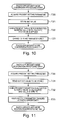
- FIG. 11 is a flow chart showing a procedure of photo opportunity mode restoration processing.
- FIG. 12 is a schematic flow chart showing another operation to handle a set value at the photo opportunity.
- the apparatus In the image capture apparatus of the present invention, with one or a plurality of parameters to be set at the photo opportunity, desired set values of the parameter are registered beforehand (setting for the photo opportunity). Moreover, the apparatus is capable of easily changing to a setting for the photo opportunity at the photo opportunity (photo opportunity function). Therefore, a user can easily change to the desired set value at the photo opportunity.
- the user selectively changes an only image capture setting option to be set again for the photo opportunity. For example, when a storage form is set to be changed to a raw form for the photo opportunity, the other setting options are not changed, and the only storage form is changed to the raw form.
- each of the photo opportunity function can be utilized at the same time.
- a setting other than the above setting it is assumed that the image is set to be captured with the continuous shoot at the photo opportunity.
- this setting and the above setting are associated with separate operation buttons, when two buttons are simultaneously pressed, both of the settings can be changed from the current settings to those for the photo opportunity.
- the user can take a picture without any sense of incongruity, when the setting is changed at the photo opportunity.
- the image capture apparatus of the present invention includes a new operation member for the photo opportunity as well as ordinary operating section having a member for image capturing.
- This new operation member for photo opportunity can be assigned to a button of the operating section or the like.
- FIG. 1 is a perspective view showing the image capture apparatus in the present embodiment.
- a photo opportunity button (second operation member) 1 is disposed on a zoom ring of the image capture apparatus. While this photo opportunity button is pressed, the set value of the image capture apparatus continues to be switched to that for the photo opportunity. While the apparatus is brought into such a mode as to use the set value for the photo opportunity (hereinafter referred to as the photo opportunity mode), this application of the mode is displayed in a finder or a preview screen.
- this button may be disposed on a camera main body portion or another portion. Another camera operation button may be assigned to this function, or another detachable switch may be provided for this function.
- FIG. 2 is a perspective view showing an image capture apparatus in a variation of the present embodiment.
- a shutter button also having a function of the photo opportunity button is separately disposed with an ordinary shutter button.
- two shutter buttons are prepared, one of the buttons is a shutter button (first operation member) 3 for usual picture taking, and the other button is a shutter button (another second operation member) 2 for the photo opportunity.
- the shutter button 2 at the photo opportunity is pressed, the switching to the setting for the photo opportunity and a release operation are executed.
- a user can select one of the shutter buttons in accordance with a picture taking situation to prepare for the photo opportunity.
- FIG. 3 is a perspective view showing an image capture apparatus in another variation of the present embodiment.
- the apparatus includes a release button portion, a grip portion, and a pressure sensor (another second operation member) 4 on a lens including a zoom ring.
- this pressure sensor 4 is strongly gripped at the photo opportunity, the setting can be switched to that for the photo opportunity.
- FIG. 4 is a perspective view showing an image capture apparatus in still another variation of the present embodiment.
- a voice recognition device 5 As a voice recognition device 5 , a microphone or the like is disposed. The voice recognition device 5 recognizes voice given by a user, and the switching for the photo opportunity can be performed responding to it.
- FIG. 5 is a block diagram showing a constitution of the image capture apparatus.
- An image capture apparatus 10 is provided with a processing section 11 , an operating section 12 , an image capture section 14 , a storage section 15 , a display section 16 , a photo opportunity input section 17 and a voice input section 18 .
- the processing section 11 generally controls an operation of the image capture apparatus 10 .
- the operating section 12 is an input device for receiving an operation instruction input from the user.
- the image capture section 14 captures an image of a subject to generate image data of the subject.
- the storage section 15 stores the set value of the parameter and the like.
- the display section 16 is a liquid crystal display which displays a menu and the like.
- the photo opportunity input section 17 is an operation member or device for switching to the set value at the photo opportunity, and corresponds to the above photo opportunity button 1 or the like.
- the voice input section 18 is a voice receiving unit for receiving the user's voice.
- FIG. 6 is a flow chart showing a schematic procedure to register the set value of the photo opportunity mode.
- the user Prior to the picture taking, the user operates the operating section 12 to set a plurality of image capture parameters for use in the usual picture taking (image capture parameter setting function, image capture parameter setting step).
- step S 01 the user selects the parameter to be changed at the photo opportunity (parameter selecting function, parameter selecting step). This selection is executed by setting the parameter to be changed from the menu displayed in the display section 16 of the image capture apparatus 10 by use of an arrow pad or the like of the operating section 12 .
- FIG. 7 is a diagram showing examples of selectable parameters.
- step S 02 the selected value of the selected parameter is selected.
- parameter “ISO sensitivity” as the set values, “auto”, “64”, “100”, “200” and “400” can be selected.
- step S 03 when the user performs a confirming operation with the operating section 12 , the selected parameter and the set value of the parameter are stored in the storage section 15 (selected parameter storage function, selected parameter storage step).
- step S 04 it is judged whether or not the selection of the parameter, the selection of the value of the parameter and the registration have been ended. If the answer to this step is no, that is, still another parameter is selected, the flow returns to the step S 01 , and the above operation is continued. In a case where the answer to the step S 04 is yes, that is, the setting is ended, when the user does an operation for ending the registration of the photo opportunity mode, the values of the plurality of parameters input up to that time are registered as one setting of the photo opportunity mode.
- the registration for the photo opportunity mode can be performed in several times, and a desired parameter can be registered in each time.
- FIG. 8 is a schematic flow chart showing an operation to handle a set value at the photo opportunity. Processing of FIG. 8 is initiated by main processing of the image capture apparatus 10 , and the processing on the setting for the photo opportunity is executed. It is to be noted that this flow chart shows an operation of the image capture apparatus 10 provided with the characteristics shown in FIGS. 1 , 3 and 4 . An embodiment shown in FIG. 2 will be described later.
- step S 10 of FIG. 8 photo opportunity function judgment processing ( FIG. 9 ) is executed.
- steps T 01 , T 02 of FIG. 9 it is judged whether or not the photo opportunity button 1 ( FIG. 1 ) has been operated or whether or not the pressure sensor 4 ( FIG. 3 ) has been operated.
- step T 05 when the photo opportunity input section 17 detects that the photo opportunity button 1 or the pressure sensor 4 has been pressed, it is checked in step T 06 whether or not the photo opportunity mode of the image capture apparatus 10 is brought into “mode 1”.
- the “mode 1” is a mode in which the photo opportunity function is turned on while the photo opportunity button 1 or the pressure sensor 4 is pressed. That is, when the finger is released from the photo opportunity button 1 or the pressure sensor 4 , the photo opportunity function does not work from the releasing time.
- mode 2 is a mode to switch the photo opportunity function from ON to OFF or from OFF to ON, every time the photo opportunity button 1 or the pressure sensor 4 is pressed. Therefore, unlike the “mode 1”, the photo opportunity button 1 or the pressure sensor 4 does not have to continue to be pressed.
- the photo opportunity function is controlled by a flag indicating whether the set value at the photo opportunity is valid or invalid.
- step T 06 In a case where the answer to the step T 06 is yes, that is, in the “mode 1”, in step T 07 , while the photo opportunity button 1 or the pressure sensor 4 is pressed, the photo opportunity function is turned on. In a case where the answer to the step T 06 is no, that is, in the “mode 2”, in step T 08 , the photo opportunity function is switched to ON or OFF.
- step T 02 the flow advances to step T 03 to check whether or not an input of voice has been made.
- the voice to be input may be sound or a word.
- a word such as “chance” or “up” may be input.
- step T 10 the voice input section 18 recognizes by voice recognition that the voice has been input, it is checked in step T 11 whether or not the input voice has a predetermined voice pattern.
- step T 12 the photo opportunity function is switched to ON or OFF.
- step T 11 the answer to the step T 11 is no, that is, the voice does not have any predetermined voice pattern, the switching of the photo opportunity function is not executed.
- step S 11 it is checked in step S 11 whether or not the photo opportunity function turns on.
- step S 12 it is checked in step S 12 whether or not the image capture apparatus 10 has already been brought into the photo opportunity mode.
- the apparatus is in the photo opportunity mode, it is indicated that the set value is changed to that for the photo opportunity.
- step S 12 In a case where the answer to the step S 12 is yes, that is, the image capture apparatus 10 is in the photo opportunity mode, the flow advances to the next step, and any processing is not especially executed. In a case where the answer to the step S 12 is no, that is, the image capture apparatus 10 is in photo opportunity mode, photo opportunity mode conversion processing ( FIG. 10 ) shown in step S 13 is executed.
- step T 20 of FIG. 10 the value of the parameter set in the image capture apparatus 10 at present is acquired, and in step T 21 , the value of the parameter is stored in the storage section 15 . Subsequently, in step T 22 , for a parameter where the present parameter value is applied, the value of the parameter is calculated and applied.
- the current “shutter speed” is calculated in the auto mode based on an exposure value, and a calculation result is set as the initial “shutter speed” in a manual mode.
- step T 23 the value of the parameter only registered in the photo opportunity mode is changed to the set value.
- step S 14 in a case where the answer to the step S 11 is no, that is, the photo opportunity function is off, it is checked in step S 14 whether or not the photo opportunity mode of the image capture apparatus 10 has already been cancelled.
- the photo opportunity mode when it is mentioned that the photo opportunity mode is cancelled, it means that the parameter is restored to the original parameter.
- step S 14 In a case where the answer to the step S 14 is yes, that is, the image capture apparatus 10 cancels the photo opportunity mode, the flow advances to the next step, and any processing is not especially executed. In a case where the answer to the step S 14 is no, that is, the image capture apparatus 10 does not cancel the photo opportunity mode, photo opportunity mode restoration processing ( FIG. 11 ) shown in step S 15 is executed.
- step T 30 of FIG. 11 the value of the parameter at the photo opportunity is acquired which is set in the image capture apparatus 10 at present. Moreover, in step T 31 , a value of the original parameter is read out which has been stored in the storage section 15 . Subsequently, in step T 32 , for a parameter to which the present parameter value is reflected, the value of the parameter is calculated, and applied.
- step T 33 the value applied only for the photo opportunity is returned to the original value.
- step S 16 the above processing on the set value at the photo opportunity is repeatedly executed until a power source is turned off. In a case where the answer to the step S 16 is no, that is, the power source is turned off, the processing ends.
- FIG. 12 is a schematic flow chart showing another operation to handle the set value at the photo opportunity. Processing of FIG. 12 is initiated with main processing of the image capture apparatus 10 , and the processing on the set value at the photo opportunity is executed. It is to be noted that this flow chart shows an operation of the image capture apparatus 10 in the embodiment shown in FIG. 2 . That is, there is shown the flow chart concerting the image capture apparatus 10 separately provided with a shutter for the photo opportunity.
- step S 21 When in step S 21 , it is detected that either of the shutter buttons 2 and 3 is half pressed, it is checked in step S 22 whether or not the shutter 2 for the photo opportunity has been operated.
- photo opportunity mode conversion processing ( FIG. 10 ) shown in step S 23 is executed.
- This photo opportunity mode conversion processing is processing to switch to the set value for the photo opportunity. Since the processing has already been described, redundant description is omitted.
- photo opportunity mode restoration processing ( FIG. 11 ) shown in step S 24 is executed.
- This photo opportunity mode restoration processing is processing to return to an original parameter set value. Since the processing has already been described, redundant description is omitted.
- this invention can be applied for a case where the user wants to easily capture an image having no importance without using much memory capacity by, for example, adopting lower grade of image quality and capturing method than ordinal image capturing.
- the section 12 shown in FIG. 5 has an image capture parameter setting function and a parameter selecting function
- the section may be referred to as an image capture parameter setting section and a parameter selecting section.
- the sections may be referred to as a selected parameter storage section.
- the shutter button 3 for the usual picture taking, which is the first operation member, may be referred to as a first shutter section which designates a timing to perform first image capture.
- the shutter button 2 at the photo opportunity, a combination of the shutter button 2 for the usual picture taking and the photo opportunity button 1 , a combination of the shutter button 2 for the usual picture taking and the pressure sensor 4 , and a combination of the shutter button 2 for the usual picture taking and the voice recognition device 5 may be referred to as a second shutter section to designate a timing to perform second image capture.
- a button is arranged on a lens or a main body of the image capture apparatus 10 , and the operation of the button or other member can alter a setting such as an image format or image size for storage.
- the operation can further alter other settings such as selection of single shot and continuous shots.
- a plurality of shutter buttons may be prepared to change the image capture mode with the operation of the shutter buttons.
- a plurality of sets of set values for the photo opportunity can be prepared beforehand, and they may appropriately be selected. Further, it can be possible that combinations of the plurality of sets of set values are allowed for use.
- the present invention includes various characteristics which have not been seen in conventional arts.
- the functions described above in the embodiments may be constituted using hardware, or realized by allowing a computer to read a program in which the functions are described by use of software.
- the functions may be constituted by appropriately selecting either of the software and the hardware.
- the functions may be realized by making the computer to read a program stored in a recording medium (not shown).
- a recording medium not shown
- any recording form may be used as long as the recording medium can record the program, and can be read by the computer.
Abstract
Description
Claims (12)
Applications Claiming Priority (2)
| Application Number | Priority Date | Filing Date | Title |
|---|---|---|---|
| JP2005-222730 | 2005-08-01 | ||
| JP2005222730A JP2007041119A (en) | 2005-08-01 | 2005-08-01 | Imaging apparatus and imaging method |
Publications (2)
| Publication Number | Publication Date |
|---|---|
| US20070025721A1 US20070025721A1 (en) | 2007-02-01 |
| US7761002B2 true US7761002B2 (en) | 2010-07-20 |
Family
ID=37694414
Family Applications (1)
| Application Number | Title | Priority Date | Filing Date |
|---|---|---|---|
| US11/493,409 Expired - Fee Related US7761002B2 (en) | 2005-08-01 | 2006-07-25 | Image capture apparatus and image capture method |
Country Status (3)
| Country | Link |
|---|---|
| US (1) | US7761002B2 (en) |
| JP (1) | JP2007041119A (en) |
| CN (1) | CN1909601A (en) |
Cited By (7)
| Publication number | Priority date | Publication date | Assignee | Title |
|---|---|---|---|---|
| US20090059497A1 (en) * | 2007-08-29 | 2009-03-05 | Nintendo Co., Ltd. | Imaging apparatus |
| US20090278764A1 (en) * | 2007-08-29 | 2009-11-12 | Nintendo Co., Ltd. | Imaging apparatus |
| US20110234857A1 (en) * | 2008-06-13 | 2011-09-29 | Nintendo Co., Ltd. | Information processing apparatus and computer-readable storage medium recording information processing program |
| US20120200758A1 (en) * | 2007-08-29 | 2012-08-09 | Nintendo Co., Ltd. | Imaging apparatus |
| US9135026B2 (en) | 2008-06-13 | 2015-09-15 | Nintendo Co., Ltd. | Information-processing apparatus having photography applications |
| US9584726B2 (en) | 2013-09-09 | 2017-02-28 | Olympus Corporation | Imaging apparatus, imaging method, and computer-readable recording medium |
| US9630099B2 (en) | 2008-10-01 | 2017-04-25 | Nintendo Co., Ltd. | Information processing device, information processing system, and launch program and storage medium storing the same providing photographing functionality |
Families Citing this family (8)
| Publication number | Priority date | Publication date | Assignee | Title |
|---|---|---|---|---|
| JP4931769B2 (en) * | 2007-09-04 | 2012-05-16 | 株式会社リコー | Imaging apparatus and imaging control method |
| JP4941758B2 (en) | 2007-09-11 | 2012-05-30 | ソニー株式会社 | Imaging device |
| JP5785428B2 (en) * | 2011-04-21 | 2015-09-30 | キヤノン株式会社 | Imaging apparatus, control method therefor, program, and storage medium |
| CN103581512B (en) * | 2012-08-02 | 2017-04-19 | 宏碁股份有限公司 | Shooting device and method |
| JP6071544B2 (en) * | 2012-12-27 | 2017-02-01 | キヤノン株式会社 | Imaging device |
| EP3032307A4 (en) * | 2013-09-24 | 2017-02-22 | Sony Corporation | Imaging device, imaging method and program |
| EP3358821B1 (en) * | 2015-09-30 | 2021-06-30 | Nikon Corporation | Imaging device and image processing device |
| CN105681675A (en) * | 2016-03-22 | 2016-06-15 | 珠海格力电器股份有限公司 | Mobile terminal, and shooting mode setting method and device |
Citations (15)
| Publication number | Priority date | Publication date | Assignee | Title |
|---|---|---|---|---|
| US4007469A (en) * | 1975-04-21 | 1977-02-08 | Polaroid Corporation | Photographic apparatus with plurality of selectively determinable operational modes |
| US5467226A (en) * | 1990-09-18 | 1995-11-14 | Canon Kabushiki Kaisha | Optical apparatus having a lens for zooming movable to a zoom area and a macro area |
| US20020093582A1 (en) * | 2001-01-12 | 2002-07-18 | Taizou Aoki | Data communication terminal and camera |
| US20030020958A1 (en) * | 2001-07-30 | 2003-01-30 | Bean Heather Noel | Non-polarizing shutter/CCD module |
| US20030052989A1 (en) * | 2001-07-18 | 2003-03-20 | Bean Heather Noel | Non-polarizing shutter/CCD module |
| US6559888B1 (en) * | 1998-03-31 | 2003-05-06 | Amir Doron | Digital camera and method of smoothing optical and digital zoom effects |
| JP2004053722A (en) | 2002-07-17 | 2004-02-19 | Fuji Photo Film Co Ltd | Camera |
| JP2004135271A (en) | 2002-09-13 | 2004-04-30 | Eastman Kodak Co | Digital camera equipped with hot key function of user interface |
| US20040174430A1 (en) * | 2003-03-07 | 2004-09-09 | Shingo Sawahara | Multifunctional mobile electronic device |
| US20050094000A1 (en) * | 2003-10-30 | 2005-05-05 | Samsung Electronics Co., Ltd. | Apparatus and method for photographing a moving picture |
| US20050253868A1 (en) * | 2004-05-17 | 2005-11-17 | Narutoshi Ageishi | Image synthesis output apparatus, image synthesis display apparatus, portable communication equipment, image synthesis output method, and program product |
| US20050265714A1 (en) * | 2004-05-28 | 2005-12-01 | Per Rosdahl | Digital shutter |
| US20060079302A1 (en) * | 2002-09-20 | 2006-04-13 | Hitachi, Ltd. | Mobile phone with camera |
| US20070133976A1 (en) * | 2005-02-28 | 2007-06-14 | Gutierrez Roman C | Shutter for miniature camera |
| US20070242940A1 (en) * | 2004-01-30 | 2007-10-18 | Naoto Yumiki | Lens Barrel and Image Device Provided with Lens Barrel, and Assembly Method of Lens Barrel |
-
2005
- 2005-08-01 JP JP2005222730A patent/JP2007041119A/en active Pending
-
2006
- 2006-07-25 US US11/493,409 patent/US7761002B2/en not_active Expired - Fee Related
- 2006-08-01 CN CNA2006101083238A patent/CN1909601A/en active Pending
Patent Citations (15)
| Publication number | Priority date | Publication date | Assignee | Title |
|---|---|---|---|---|
| US4007469A (en) * | 1975-04-21 | 1977-02-08 | Polaroid Corporation | Photographic apparatus with plurality of selectively determinable operational modes |
| US5467226A (en) * | 1990-09-18 | 1995-11-14 | Canon Kabushiki Kaisha | Optical apparatus having a lens for zooming movable to a zoom area and a macro area |
| US6559888B1 (en) * | 1998-03-31 | 2003-05-06 | Amir Doron | Digital camera and method of smoothing optical and digital zoom effects |
| US20020093582A1 (en) * | 2001-01-12 | 2002-07-18 | Taizou Aoki | Data communication terminal and camera |
| US20030052989A1 (en) * | 2001-07-18 | 2003-03-20 | Bean Heather Noel | Non-polarizing shutter/CCD module |
| US20030020958A1 (en) * | 2001-07-30 | 2003-01-30 | Bean Heather Noel | Non-polarizing shutter/CCD module |
| JP2004053722A (en) | 2002-07-17 | 2004-02-19 | Fuji Photo Film Co Ltd | Camera |
| JP2004135271A (en) | 2002-09-13 | 2004-04-30 | Eastman Kodak Co | Digital camera equipped with hot key function of user interface |
| US20060079302A1 (en) * | 2002-09-20 | 2006-04-13 | Hitachi, Ltd. | Mobile phone with camera |
| US20040174430A1 (en) * | 2003-03-07 | 2004-09-09 | Shingo Sawahara | Multifunctional mobile electronic device |
| US20050094000A1 (en) * | 2003-10-30 | 2005-05-05 | Samsung Electronics Co., Ltd. | Apparatus and method for photographing a moving picture |
| US20070242940A1 (en) * | 2004-01-30 | 2007-10-18 | Naoto Yumiki | Lens Barrel and Image Device Provided with Lens Barrel, and Assembly Method of Lens Barrel |
| US20050253868A1 (en) * | 2004-05-17 | 2005-11-17 | Narutoshi Ageishi | Image synthesis output apparatus, image synthesis display apparatus, portable communication equipment, image synthesis output method, and program product |
| US20050265714A1 (en) * | 2004-05-28 | 2005-12-01 | Per Rosdahl | Digital shutter |
| US20070133976A1 (en) * | 2005-02-28 | 2007-06-14 | Gutierrez Roman C | Shutter for miniature camera |
Non-Patent Citations (1)
| Title |
|---|
| Chinese Office Action to Chinese Patent Application No. 2006101083238, mailed Dec. 7, 2007 (4 pgs.) with translation (2 pgs.). |
Cited By (20)
| Publication number | Priority date | Publication date | Assignee | Title |
|---|---|---|---|---|
| US9264694B2 (en) | 2007-08-29 | 2016-02-16 | Nintendo Co., Ltd. | Hand-held imaging apparatus and storage medium storing program |
| US8917985B2 (en) | 2007-08-29 | 2014-12-23 | Nintendo Co., Ltd. | Imaging apparatus |
| US20090278974A1 (en) * | 2007-08-29 | 2009-11-12 | Nintendo Co., Ltd. | Hand-held imaging apparatus and storage medium storing program |
| US9894344B2 (en) | 2007-08-29 | 2018-02-13 | Nintendo Co., Ltd. | Camera device |
| US20120200758A1 (en) * | 2007-08-29 | 2012-08-09 | Nintendo Co., Ltd. | Imaging apparatus |
| US8608392B2 (en) * | 2007-08-29 | 2013-12-17 | Nintendo Co., Ltd. | Imaging apparatus |
| US9344706B2 (en) | 2007-08-29 | 2016-05-17 | Nintendo Co., Ltd. | Camera device |
| US20090059497A1 (en) * | 2007-08-29 | 2009-03-05 | Nintendo Co., Ltd. | Imaging apparatus |
| US9325967B2 (en) | 2007-08-29 | 2016-04-26 | Nintendo Co., Ltd. | Imaging apparatus |
| US20090278764A1 (en) * | 2007-08-29 | 2009-11-12 | Nintendo Co., Ltd. | Imaging apparatus |
| US10437424B2 (en) | 2008-06-13 | 2019-10-08 | Nintendo Co., Ltd. | Information processing apparatus and computer-readable storage medium recording information processing program |
| US8913172B2 (en) | 2008-06-13 | 2014-12-16 | Nintendo Co., Ltd. | Information processing apparatus and computer-readable storage medium recording information processing program |
| US20110234857A1 (en) * | 2008-06-13 | 2011-09-29 | Nintendo Co., Ltd. | Information processing apparatus and computer-readable storage medium recording information processing program |
| US9256449B2 (en) | 2008-06-13 | 2016-02-09 | Nintendo Co., Ltd. | Menu screen for information processing apparatus and computer-readable storage medium recording information processing program |
| US10509538B2 (en) | 2008-06-13 | 2019-12-17 | Nintendo Co., Ltd. | Information processing apparatus having a photographing-enabled state |
| US9135026B2 (en) | 2008-06-13 | 2015-09-15 | Nintendo Co., Ltd. | Information-processing apparatus having photography applications |
| US10525334B2 (en) | 2008-10-01 | 2020-01-07 | Nintendo Co., Ltd. | System and device for communicating images |
| US9630099B2 (en) | 2008-10-01 | 2017-04-25 | Nintendo Co., Ltd. | Information processing device, information processing system, and launch program and storage medium storing the same providing photographing functionality |
| US10124247B2 (en) | 2008-10-01 | 2018-11-13 | Nintendo Co., Ltd. | System and device for communicating images |
| US9584726B2 (en) | 2013-09-09 | 2017-02-28 | Olympus Corporation | Imaging apparatus, imaging method, and computer-readable recording medium |
Also Published As
| Publication number | Publication date |
|---|---|
| JP2007041119A (en) | 2007-02-15 |
| US20070025721A1 (en) | 2007-02-01 |
| CN1909601A (en) | 2007-02-07 |
Similar Documents
| Publication | Publication Date | Title |
|---|---|---|
| US7761002B2 (en) | Image capture apparatus and image capture method | |
| JP4045525B2 (en) | Image quality selection method and digital camera | |
| JP4293089B2 (en) | Imaging apparatus, imaging control method, and program | |
| JP4481842B2 (en) | Imaging apparatus and control method thereof | |
| JP2002077673A (en) | Electronic camera | |
| JP4862741B2 (en) | Imaging apparatus, imaging signal processing method, and program | |
| JP3909614B2 (en) | Information recording / reproducing apparatus and recording medium | |
| US7746389B2 (en) | Image capture apparatus including generation of backup data | |
| JP2003304484A (en) | Electronic camera | |
| JP4680022B2 (en) | Imaging device | |
| JP2004165780A (en) | Electronic camera | |
| US20070081082A1 (en) | Electronic camera | |
| JP4434449B2 (en) | Electronic camera | |
| JP4570171B2 (en) | Information processing apparatus and recording medium | |
| JP2005328224A (en) | Digital camera | |
| JP2005244769A (en) | Digital camera | |
| JP4671989B2 (en) | camera | |
| JP5151947B2 (en) | Imaging apparatus and program thereof | |
| JP4423681B2 (en) | Information processing apparatus and recording medium | |
| JP2007228233A (en) | Photographic device | |
| JP2006033752A (en) | Digital camera | |
| JP4227066B2 (en) | Image capturing apparatus and image reproducing method of image capturing apparatus | |
| JP4437562B2 (en) | Information processing apparatus and storage medium | |
| JP2006245654A (en) | Electronic camera | |
| JP4038842B2 (en) | Information processing device |
Legal Events
| Date | Code | Title | Description |
|---|---|---|---|
| AS | Assignment |
Owner name: OLYMPUS IMAGING CORP., JAPAN Free format text: ASSIGNMENT OF ASSIGNORS INTEREST;ASSIGNOR:AKAGANE, TSUNETAKA;REEL/FRAME:018138/0680 Effective date: 20060718 Owner name: SENSORMATIC ELECTRONICS CORPORATION, FLORIDA Free format text: ASSIGNMENT OF ASSIGNORS INTEREST;ASSIGNOR:LIU, NEN-CHIN;REEL/FRAME:018138/0755 Effective date: 20060724 |
|
| FEPP | Fee payment procedure |
Free format text: PAYOR NUMBER ASSIGNED (ORIGINAL EVENT CODE: ASPN); ENTITY STATUS OF PATENT OWNER: LARGE ENTITY |
|
| FPAY | Fee payment |
Year of fee payment: 4 |
|
| AS | Assignment |
Owner name: OLYMPUS CORPORATION, JAPAN Free format text: MERGER;ASSIGNOR:OLYMPUS IMAGING CORP.;REEL/FRAME:036616/0332 Effective date: 20150401 |
|
| AS | Assignment |
Owner name: OLYMPUS CORPORATION, JAPAN Free format text: CHANGE OF ADDRESS;ASSIGNOR:OLYMPUS CORPORATION;REEL/FRAME:039344/0502 Effective date: 20160401 |
|
| FEPP | Fee payment procedure |
Free format text: MAINTENANCE FEE REMINDER MAILED (ORIGINAL EVENT CODE: REM.) |
|
| LAPS | Lapse for failure to pay maintenance fees |
Free format text: PATENT EXPIRED FOR FAILURE TO PAY MAINTENANCE FEES (ORIGINAL EVENT CODE: EXP.); ENTITY STATUS OF PATENT OWNER: LARGE ENTITY |
|
| STCH | Information on status: patent discontinuation |
Free format text: PATENT EXPIRED DUE TO NONPAYMENT OF MAINTENANCE FEES UNDER 37 CFR 1.362 |
|
| FP | Lapsed due to failure to pay maintenance fee |
Effective date: 20180720 |