US7776479B2 - Micro-electro-mechanical systems phosphoric acid fuel cell - Google Patents
Micro-electro-mechanical systems phosphoric acid fuel cell Download PDFInfo
- Publication number
- US7776479B2 US7776479B2 US11/119,525 US11952505A US7776479B2 US 7776479 B2 US7776479 B2 US 7776479B2 US 11952505 A US11952505 A US 11952505A US 7776479 B2 US7776479 B2 US 7776479B2
- Authority
- US
- United States
- Prior art keywords
- phosphoric acid
- electrolyte
- porous
- fuel cell
- pafc
- Prior art date
- Legal status (The legal status is an assumption and is not a legal conclusion. Google has not performed a legal analysis and makes no representation as to the accuracy of the status listed.)
- Active, expires
Links
Images


Classifications
-
- H—ELECTRICITY
- H01—ELECTRIC ELEMENTS
- H01M—PROCESSES OR MEANS, e.g. BATTERIES, FOR THE DIRECT CONVERSION OF CHEMICAL ENERGY INTO ELECTRICAL ENERGY
- H01M8/00—Fuel cells; Manufacture thereof
- H01M8/02—Details
- H01M8/0289—Means for holding the electrolyte
- H01M8/0293—Matrices for immobilising electrolyte solutions
-
- H—ELECTRICITY
- H01—ELECTRIC ELEMENTS
- H01M—PROCESSES OR MEANS, e.g. BATTERIES, FOR THE DIRECT CONVERSION OF CHEMICAL ENERGY INTO ELECTRICAL ENERGY
- H01M8/00—Fuel cells; Manufacture thereof
- H01M8/08—Fuel cells with aqueous electrolytes
- H01M8/086—Phosphoric acid fuel cells [PAFC]
-
- H—ELECTRICITY
- H01—ELECTRIC ELEMENTS
- H01M—PROCESSES OR MEANS, e.g. BATTERIES, FOR THE DIRECT CONVERSION OF CHEMICAL ENERGY INTO ELECTRICAL ENERGY
- H01M8/00—Fuel cells; Manufacture thereof
- H01M8/04—Auxiliary arrangements, e.g. for control of pressure or for circulation of fluids
- H01M8/04007—Auxiliary arrangements, e.g. for control of pressure or for circulation of fluids related to heat exchange
- H01M8/04067—Heat exchange or temperature measuring elements, thermal insulation, e.g. heat pipes, heat pumps, fins
- H01M8/04074—Heat exchange unit structures specially adapted for fuel cell
-
- Y—GENERAL TAGGING OF NEW TECHNOLOGICAL DEVELOPMENTS; GENERAL TAGGING OF CROSS-SECTIONAL TECHNOLOGIES SPANNING OVER SEVERAL SECTIONS OF THE IPC; TECHNICAL SUBJECTS COVERED BY FORMER USPC CROSS-REFERENCE ART COLLECTIONS [XRACs] AND DIGESTS
- Y02—TECHNOLOGIES OR APPLICATIONS FOR MITIGATION OR ADAPTATION AGAINST CLIMATE CHANGE
- Y02E—REDUCTION OF GREENHOUSE GAS [GHG] EMISSIONS, RELATED TO ENERGY GENERATION, TRANSMISSION OR DISTRIBUTION
- Y02E60/00—Enabling technologies; Technologies with a potential or indirect contribution to GHG emissions mitigation
- Y02E60/30—Hydrogen technology
- Y02E60/50—Fuel cells
Definitions
- the present invention relates to phosphoric acid fuel cells and more particularly to electromechanical systems phosphoric acid fuel cells.
- the phosphoric acid fuel cell has a power-generating cell which is provided with an electrolyte-electrode assembly comprising an anode electrode, a cathode electrode, and an electrolyte layer interposed between the both electrodes.
- the electrolyte layer is generally constructed such that pores of a porous silicon carbide member is impregnated with concentrated phosphoric acid (liquid electrolyte).
- concentrated phosphoric acid liquid electrolyte
- another type of the electrolyte layer is also known, in which a membrane of basic polymer such as polybenzimidazole is impregnated with phosphoric acid or sulfuric acid (see U.S. Pat. No. 5,525,436).
- a membrane of basic polymer such as polybenzimidazole is impregnated with phosphoric acid or sulfuric acid (see U.S. Pat. No. 5,525,436).
- the phosphoric acid fuel cell a predetermined number of the power-generating cells are electrically connected in series with each other to provide a fuel cell stack which is accommodated in a container.
- the hydrogen in the hydrogen-containing gas is ionized on the anode electrode in a manner as represented by the following reaction formula (A).
- A the hydrogen ion and the electron are generated. 2H2 ⁇ 4H + +4 e
- the hydrogen ion is moved toward the cathode electrode via the electrolyte layer.
- the electron is extracted by an external circuit which is electrically connected to the anode electrode and the cathode electrode. The electron is utilized as the DC electric energy to energize the external circuit, and then it arrives at the cathode electrode.
- reaction formula (B) The reaction according to the reaction formula (B) is slow as compared with the reaction formula (A). That is, the reaction represented by the reaction formula (B) constitutes the rate-determining step in the overall cell reaction of the phosphoric acid fuel cell.”
- the present invention provides a phosphoric acid fuel cell system comprising a porous electrolyte support, a phosphoric acid electrolyte in the porous electrolyte support, a cathode electrode contacting the phosphoric acid electrolyte, and an anode electrode contacting the phosphoric acid electrolyte.
- the fuel cell system is ideally suited, both thermally and chemically, for operation in conjunction with a methanol reformer.
- the phosphoric acid fuel cell system can operate from 150° to 250° C.
- the phosphoric acid fuel cell system comprises less individual parts than conventional fuel cell systems, and has other advantageous properties as well; including very high surface areas, very thin membranes and membrane electrode assemblies.
- the phosphoric acid fuel cell system is produced by the steps of providing a porous electrolyte support, filling the porous electrolyte support with a phosphoric acid electrolyte, positioning a cathode electrode in contact with the phosphoric acid electrolyte, and positioning an anode electrode contacting the phosphoric acid electrolyte.
- the step of filling the porous electrolyte support with a phosphoric acid electrolyte comprises wicking the phosphoric acid electrolyte into the porous electrolyte support by capillary action.
- FIG. 1 illustrates one embodiment of a phosphoric acid fuel cell constructed in accordance with the present invention.
- FIG. 2 shows an enlarged view of a section of the phosphoric acid fuel cell shown in FIG. 1 .
- FIG. 3 shows an alternative version of the enlarged view of a section of the phosphoric acid fuel cell shown in FIG. 1 .
- FIG. 4 shows a three dimensional “lattice” structure.
- FIG. 5 shows a high aspect ratio micropore structure.
- FIG. 6 shows an embodiment that includes arrays of micropores in a microchannel flow field.
- FIG. 7 illustrates another embodiment of a phosphoric acid fuel cell constructed in accordance with the present invention.
- FIG. 8 illustrates another embodiment of a phosphoric acid fuel cell constructed in accordance with the present invention.
- FIG. 9 illustrates a bipolar stack phosphoric acid fuel cell configuration.
- FIG. 10 illustrates a non-planar phosphoric acid fuel cell configuration using a porous ceramic or insulator electrolyte support.
- FIG. 11 illustrates another embodiment of a non-planar phosphoric acid fuel cell configuration using a porous ceramic or insulator electrolyte support.
- FIG. 12 illustrates another embodiment of a PAFC construted in accordance with the present invention.
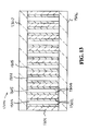
- FIG. 13 illustrates another embodiment of a phosphoric acid fuel cell constructed in accordance with the present invention.
- PAFC phosphoric acid fuel cell
- the PAFC 100 is produced utilizing different methods of manufacture, particularly M icro E lectro M echanical S ystems (MEMS) technology.
- MEMS M icro E lectro M echanical S ystems
- the PAFC 100 includes the following structural components: phosphoric acid reservoir 101 , high surface area silicon micropores 102 , porous cathode electrode 103 , cathode flow fields 104 , silicone substrate 105 , phosphoric acid electrolyte 106 , silicone substrate 107 , porous anode electrode 108 , high surface area silicon micropores 109 , and anode flow fields 110 .
- FIG. 2 an enlarged view of a section of the PAFC 100 is shown.
- the enlarged section includes electric insulation (oxide) 201 , electrolyte, 202 , silicon 203 , and electrode with catalyst 204 .
- FIG. 3 an alternative version of the enlarged view of a section of the PAFC 100 is shown.
- the alternative version enlarged section includes porous electrode with catalyst 301 .
- the other side of the wafer is masked and etched with a high density matrix of pores, up to about several microns across, or possibly up to many tens of microns in diameter, width and aspect ratio of up to about 20, until the pores break through to the other side to the flow field microchannels.
- the pores are etched by various deep anisotropic etching techniques, including plasma etch, wet chemical etch, laser machining, electrochemical, or photo-electrochemical etching.
- the phosphoric acid electrolyte 106 is added to the edge of the porous matrix and is wicked in by capillary action to form a membrane-electrode-assembly. This membrane-electrode-assembly (MEA) is then fitted between two flow fields with a sealing gasket around the edge.
- the PAFC 100 is ideally suited, both thermally and chemically, for operation in conjunction with a methanol reformer.
- PFACs can operate from 150° to 250° C. Above 150° C., the kinetics of carbon monoxide turnover on the fuel cell electrode become favorable, and the presence of one percent carbon monoxide in the fuel stream does not significantly degrade performance. Furthermore, PAFCs do not require humidification of their gas streams for good performance eliminating the necessity for a tight operating window.
- Prior art PAFCs are comprised of several parts. At the center is a porous matrix which holds the phosphoric acid electrolyte. This is typically made of a sintered TeflonTM/silicon carbide matrix tens of microns thick. The TeflonTM/silicon carbide matrix is situated between two pieces of porous carbon fiber sheets, or gas diffusion layers (GDLs), which have had carbon supported platinum electrodes sprayed or screened onto one side. The electrodes and their supporting GDLs also contain a TeflonTM matrix created by the incorporation of TeflonTM particles into the GDLs during fabrication and subsequent sintering.
- GDLs gas diffusion layers
- This TeflonTM matrix maintains gas access to the catalyst sites by preventing the electrodes and GDLs from being completely flooded with phosphoric acid.
- the phosphoric acid electrolyte is added to the edge of the sintered frit and is wicked in by capillary action to form a membrane-electrode-assembly.
- This membrane-electrode-assembly (MEA) is then fitted between two flow fields with a sealing gasket around the edge.
- the flow fields are typically machined out of graphite because graphite has good corrosion resistance and electrical conductivity. In many cases flow fields are machined into both sides of a graphite plate, resulting in a bipolar plate. Electrolyte reservoirs may also be machined into the graphite plate. This technique results in about 5 to 7 pieces required per cell: one bipolar plate, one gasket, one electrolyte matrix, two GDL/electrode layers
- the PAFC 100 comprises less individual parts than conventional PAFCs.
- the PAFC 100 also has other advantageous properties than conventional PAFCs.
- the other advantageous properties include very high surface area, very thin membranes, and very thin membrane electrode assemblies.
- Another approach of producing the PAFC 100 is electrochemical etching techniques that form a porous silicon matrix having random porosity. Examples of this include silica aerogel or solgel structures, anodized alumina, and sintered frits which can be attached to the silicon electrode structure.
- the electrolyte reservoir 101 is incorporated into this etch procedure as well.
- the “pore side” of the wafer is processed to give it an oxide or nitride (non-conducting) surface, while the flow field side is sputter coated with platinum or gold or other protective, conductive coating.
- a fuel cell “stack,” utilizing multiple cells placed back to back, can be made by placing a thin graphite or corrosion resistant metal sheet between opposing flow fields, thereby using the conductive silicon as the electrical conductor in a bipolar stack configuration.
- FIG. 4 A three dimensional “lattice” structure is shown in FIG. 4 .
- the three dimensional “lattice” structure is generally designated by the reference numeral 400 .
- the three dimensional “lattice” structure 400 includes a lattice element 401 extending in the X axis, a lattice element 402 extending in the Y axis, and a lattice element 403 extending in the Z axis.
- the high aspect ratio micropore structure is generally designated by the reference numeral 500 .
- the high aspect ratio micropore structure 500 includes a micropore 501 .
- FIG. 6 an embodiment of the present invention that includes arrays of micropores in a microchannel flow field is shown.
- the embodiment that includes arrays of micropores in a microchannel flow field is generally designated by the reference numeral 600 .
- the micropores 601 provide a high surface area structure.
- the PAFC 700 includes the following structural components: a porous electrolyte support 701 , air or oxygen 702 , cathode 703 , current carrying bus or manifold 704 , fuel 705 , and anode 706 .
- the PAFC 700 utilizes any electrically insulating porous structure or layer as a structure 701 to hold the phosphoric acid, with electrodes 703 and 706 formed on opposing sides of the porous structure 701 .
- this material include porous alumina, possibly formed through an anodization process, porous glass, polymers, anodized or insulated metals, porous silicon, aerogels, or other materials used to make frits and filters.
- the porous structure must wet to phosphoric acid to ensure the phosphoric acid electrolyte is retained in the support structure. This can further be achieved by chemical or coating processes to the porous materials.
- the porous structure is incorporated in a planar configuration as shown in FIG. 7 .
- the PAFC 800 includes the following structural components: upper fuel electrode 801 , current collector 802 , upper and lower air electrodes 803 , upper and lower porous electrolyte supports 804 , lower fuel electrode 805 , air manifold or flow field 806 , and fuel manifold or flow field 807 .
- the porous structure is incorporated in a configuration as shown in FIG. 8 , wherein current carrying electrodes are applied or a gas manifold can be used to stack the individual membrane electrode assemblies.
- the insulating electrolyte support layer may further be structured in such a manner as to increase overall surface area of the electrode, including cylindrical, serpentine, or other configurations. This can be accomplished by forming a mold in which a green state frit is placed, then sintered to hold the shape prior to depositing electrodes and electrolyte.
- the PAFC is identified generally by the reference numeral 900 .
- the PAFC 900 is a bipolar stack embodiment.
- the PAFC 900 includes the following structural components: fuel electrodes 901 , air electrodes 902 , current collector 903 , porous electrolyte support 904 , air manifold or flow field 905 , and fuel manifold or flow field 906 .
- the porous structure 904 is incorporated in a configuration as shown in FIG. 9 , wherein current carrying electrodes are used to stack the individual membrane electrode assemblies.
- the insulating electrolyte support layer may further be structured in such a manner as to increase overall surface area of the electrode, including cylindrical, serpentine, or other configurations. This can be accomplished by forming a mold in which a green state frit is placed, then sintered to hold the shape prior to depositing electrodes and electrolyte.
- the PAFC 1000 includes the following structural components: porous electrolyte support 1001 , cathode 1002 , anode 1003 , current carrying bus or manifold 1004 , fuel 1005 , and air or oxygen 1006 .
- the PAFC 1000 is formed in the shape illustrated in silicon or aluminum through approaches such as etching or machining, then making the structure porous to create a continuous layer that holds the shape of the initial structure as shown in FIG. 10 .
- the phosphoric acid electrolyte and electrodes are deposited on opposing sides of the porous support structure.
- the PAFC 1000 is a non-planar phosphoric acid fuel cell configuration using a porous ceramic or insulator electrolyte support.
- the membrane can be configured in any shape as long as opposing electrodes and surfaces are isolated by seals to only air or hydrogen flows to the electrode.
- very deep channels are formed on opposing surfaces of a substrate.
- the substrate may be silicon or aluminum, and the channels can be up to several millimeters deep, and as narrow as a few microns.
- the remaining walls between adjacent microchannels may be 10-100 ⁇ m wide.
- the walls are then made to be porous by anodic, electrochemical, or other etching techniques. Once the structure has been made completely porous, an electrolyte is deposited into the porous support structure through techniques such as wicking, or flowing the electrolyte through the open microchannels.
- the PAFC is identified generally by the reference numeral 1100 .
- the PAFC 1100 includes the following structural components: porous electrolyte support 1101 , fuel electrode 1102 , air electrode 1103 , upper microchannel 1104 , and lower microchannel 1005 .
- the PAFC 1100 is a non-planar phosphoric acid fuel cell configuration using porous ceramic or insulator electrolyte support.
- the membrane can be configured in any shape as long as opposing electrodes and surfaces are isolated by seals to only air or hydrogen flows to the electrode.
- the PAFC 1100 is produced utilizing different methods of manufacture, particularly M icro E lectro M echanical S ystems (MEMS) technology.
- the porous electrolyte support 1101 may be silicon or aluminum, and the channels 1004 and 10005 can be up to several millimeters deep, and as narrow as a few microns. The remaining walls between adjacent microchannels may be 10-100 ⁇ m wide. The walls are then made to be porous by anodic, electrochemical, or other etching techniques. Once the structure has been made completely porous, an electrolyte is deposited into the porous support structure through techniques such as wicking, or flowing the electrolyte through the open microchannels. Air flows along the microchannels 1104 and 1105 for higher effective surface area.
- MEMS M icro E lectro M echanical S ystems
- the PAFC is identified generally by the reference numeral 1200 .
- the PAFC 1200 includes the following structural components: porous electrolyte support 1201 , fuel electrode 1202 , air electrode 1203 , upper microchannel 1204 , and lower microchannel 1005 .
- the PAFC 1200 is a non-planar phosphoric acid fuel cell configuration using porous ceramic or insulator electrolyte support.
- the membrane can be configured in any shape as long as opposing electrodes and surfaces are isolated by seals to only air or hydrogen flows to the electrode.
- the PAFC 1200 is produced utilizing different methods of manufacture, particularly M icro E lectro M echanical S ystems (MEMS) technology. Electrodes are then deposited on each side of the porous electrolyte membrane 1201 , forming a very high electrode surface as shown in FIG. 12 .
- the porous electrolyte support 1201 may be silicon or aluminum, and the channels 1004 and 10005 can be up to several millimeters deep, and as narrow as a few microns. The remaining walls between adjacent microchannels may be 10-100 ⁇ m wide. The walls are then made to be porous by anodic, electrochemical, or other etching techniques.
- an electrolyte is deposited into the porous support structure through techniques such as wicking, or flowing the electrolyte through the open microchannels, which then absorbs or wicks into the porous ridge structure. Air and fuel flows along the microchannels 1204 and 1205 , respectively, for higher effective surface area.
- the PAFC is identified generally by the reference numeral 1300 .
- the PAFC 1300 includes the following structural components: porous electrolyte support 1301 , fuel electrodes 1302 , fuel microchannels 1303 containing fuel, air electrodes 1304 , air microchannels 1305 containing air, bottom support 1206 , and upper support 1307 .
- the fuel microchannels 1303 containing fuel and the air microchannels 1305 containing air are positioned between the bottom support 1306 and the upper support 1307 in alternating fashion.
- the PAFC 1300 is produced utilizing different methods of manufacture, particularly M icro E lectro M echanical S ystems (MEMS) technology.
- MEMS M icro E lectro M echanical S ystems
- the PAFC 1300 is a microchannel phosphoric acid fuel cell having a microchannel array etched in a substrate that may have depths up to several millimeters and widths ranging from 10-1000 ⁇ m. The remaining walls are 1-500 ⁇ m wide. Once the channels are etched, the walls are made porous by an anodizing or electrochemical etch, or other etching techniques used to make materials porous.
- the bottom support layer 1306 and the upper support layer 1307 may be porous, but are primarily non-porous.
- the sidewalls are coated with electrodes. The electrode is not continuous over the top surface. This is accomplished by using photolithographic techniques or a “lift off” approach.
- the porous walls are filled with phosphoric acid.
- a non-porous cap layer is bonded to the top surface to form a continuous, sealed microchannel array. If air and fuel flow in adjacent and alternating microchannels, each separating wall represents a fuel cell, with the entire array representing a fuel cell stack. Electrical connections to alternating electrodes can be made at the end of the channels, and bussed accordingly for optimal power output.
- the effective catalyst/electrode surface area can be substantially increased by (1) the addition of a platinum nanoparticle supported on carbon black powder or (2) the introduction of carbon nanotubes into and around the pores on the flow field/conductive side of the wafer prior to charging with phosphoric acid.
- platinum on other conductive supports of high surface area to volume ratio would also function well in this regard.
- Other high surface area, porous electrode materials and compositions may be used, including the range of materials known to those familiar in the art.
- a TeflonTM-containing emulsion can be added to the carbon/catalyst mixture and sintered to limit the intrusion of phosphoric acid into the catalyst layer.
- TeflonTM-containing emulsion is also expected to create a more favorable electrolyte/gas interface at the catalyst sites.
- the use of hydrophobic/hydrophilic mixtures of carbon particles may also provide a similar, useful partition of the gas and electrolyte domains, leading to improved performance.
Abstract
Description
2H2→4H++4e (A)
The hydrogen ion is moved toward the cathode electrode via the electrolyte layer. On the other hand, the electron is extracted by an external circuit which is electrically connected to the anode electrode and the cathode electrode. The electron is utilized as the DC electric energy to energize the external circuit, and then it arrives at the cathode electrode. The hydrogen ion moved to the cathode electrode and the electron arrived at the cathode electrode via the external circuit cause the reaction as represented by the following reaction formula (B) together with the oxygen in the oxygen-containing gas supplied to the cathode electrode.
O2+4H++4e→2H2O (B)
The reaction according to the reaction formula (B) is slow as compared with the reaction formula (A). That is, the reaction represented by the reaction formula (B) constitutes the rate-determining step in the overall cell reaction of the phosphoric acid fuel cell.”
Claims (5)
Priority Applications (3)
| Application Number | Priority Date | Filing Date | Title |
|---|---|---|---|
| US11/119,525 US7776479B2 (en) | 2004-04-29 | 2005-04-28 | Micro-electro-mechanical systems phosphoric acid fuel cell |
| US12/829,331 US8715882B2 (en) | 2004-04-29 | 2010-07-01 | High power density fuel cell comprising an array of microchannels |
| US12/829,493 US7855018B2 (en) | 2004-04-29 | 2010-07-02 | Micro-electro-mechanical systems phosphoric acid fuel cell |
Applications Claiming Priority (2)
| Application Number | Priority Date | Filing Date | Title |
|---|---|---|---|
| US56675904P | 2004-04-29 | 2004-04-29 | |
| US11/119,525 US7776479B2 (en) | 2004-04-29 | 2005-04-28 | Micro-electro-mechanical systems phosphoric acid fuel cell |
Related Child Applications (2)
| Application Number | Title | Priority Date | Filing Date |
|---|---|---|---|
| US12/829,331 Continuation-In-Part US8715882B2 (en) | 2004-04-29 | 2010-07-01 | High power density fuel cell comprising an array of microchannels |
| US12/829,493 Division US7855018B2 (en) | 2004-04-29 | 2010-07-02 | Micro-electro-mechanical systems phosphoric acid fuel cell |
Publications (2)
| Publication Number | Publication Date |
|---|---|
| US20050260485A1 US20050260485A1 (en) | 2005-11-24 |
| US7776479B2 true US7776479B2 (en) | 2010-08-17 |
Family
ID=42992451
Family Applications (2)
| Application Number | Title | Priority Date | Filing Date |
|---|---|---|---|
| US11/119,525 Active 2029-06-15 US7776479B2 (en) | 2004-04-29 | 2005-04-28 | Micro-electro-mechanical systems phosphoric acid fuel cell |
| US12/829,493 Active US7855018B2 (en) | 2004-04-29 | 2010-07-02 | Micro-electro-mechanical systems phosphoric acid fuel cell |
Family Applications After (1)
| Application Number | Title | Priority Date | Filing Date |
|---|---|---|---|
| US12/829,493 Active US7855018B2 (en) | 2004-04-29 | 2010-07-02 | Micro-electro-mechanical systems phosphoric acid fuel cell |
Country Status (1)
| Country | Link |
|---|---|
| US (2) | US7776479B2 (en) |
Families Citing this family (5)
| Publication number | Priority date | Publication date | Assignee | Title |
|---|---|---|---|---|
| US8715882B2 (en) * | 2004-04-29 | 2014-05-06 | Lawrene Livermore National Security, LLC. | High power density fuel cell comprising an array of microchannels |
| US7947405B2 (en) * | 2004-09-29 | 2011-05-24 | Giner Electrochemical Systems, Llc | Solid polymer electrolyte composite membrane comprising porous ceramic support |
| US8557480B2 (en) | 2009-08-26 | 2013-10-15 | Lawrence Livermore National Security, Llc | High power density fuel cell comprising an array of microchannels |
| EP2553751A4 (en) | 2010-04-01 | 2014-07-16 | Trenergi Corp | High temperature membrane electrode assembly with high power density and corresponding method of making |
| CN112786934A (en) * | 2019-11-11 | 2021-05-11 | 钱志刚 | Phosphoric acid fuel cell power system taking methanol as raw material and power generation method thereof |
Citations (8)
| Publication number | Priority date | Publication date | Assignee | Title |
|---|---|---|---|---|
| US4463067A (en) * | 1982-09-30 | 1984-07-31 | Engelhard Corporation | Fuel cell and system for supplying electrolyte thereto utilizing cascade feed |
| US20020012823A1 (en) | 2000-06-29 | 2002-01-31 | Honda Giken Kogyo Kabushiki Kaisha | Method of operating phosphoric acid fuel cell |
| US20020012822A1 (en) | 2000-06-30 | 2002-01-31 | Honda Giken Kogyo Kabushiki Kaisha | Method of operating phosphoric acid fuel cell |
| US20020028372A1 (en) | 1999-11-17 | 2002-03-07 | Ohlsen Leroy J. | Hydrodynamic transport and flow channel passageways associated with fuel cell electrode structures and fuel cell electrode stack assemblies |
| US20020041991A1 (en) | 1999-11-17 | 2002-04-11 | Chan Chung M. | Sol-gel derived fuel cell electrode structures and fuel cell electrode stack assemblies |
| US20030044674A1 (en) | 1999-11-17 | 2003-03-06 | Mallari Jonathan C. | Silicon-based fuel cell electrode structures and fuel cell electrode stack assemblies |
| US20040009377A1 (en) | 2002-06-14 | 2004-01-15 | Honda Giken Kogyo Kabushiki Kaisha | Method of operating phosphoric acid fuel cell |
| US6835488B2 (en) * | 2000-05-08 | 2004-12-28 | Honda Giken Kogyo Kabushiki Kaisha | Fuel cell with patterned electrolyte/electrode interface |
-
2005
- 2005-04-28 US US11/119,525 patent/US7776479B2/en active Active
-
2010
- 2010-07-02 US US12/829,493 patent/US7855018B2/en active Active
Patent Citations (10)
| Publication number | Priority date | Publication date | Assignee | Title |
|---|---|---|---|---|
| US4463067A (en) * | 1982-09-30 | 1984-07-31 | Engelhard Corporation | Fuel cell and system for supplying electrolyte thereto utilizing cascade feed |
| US20020028372A1 (en) | 1999-11-17 | 2002-03-07 | Ohlsen Leroy J. | Hydrodynamic transport and flow channel passageways associated with fuel cell electrode structures and fuel cell electrode stack assemblies |
| US20020041991A1 (en) | 1999-11-17 | 2002-04-11 | Chan Chung M. | Sol-gel derived fuel cell electrode structures and fuel cell electrode stack assemblies |
| US20030044674A1 (en) | 1999-11-17 | 2003-03-06 | Mallari Jonathan C. | Silicon-based fuel cell electrode structures and fuel cell electrode stack assemblies |
| US6835488B2 (en) * | 2000-05-08 | 2004-12-28 | Honda Giken Kogyo Kabushiki Kaisha | Fuel cell with patterned electrolyte/electrode interface |
| US20020012823A1 (en) | 2000-06-29 | 2002-01-31 | Honda Giken Kogyo Kabushiki Kaisha | Method of operating phosphoric acid fuel cell |
| US6703152B2 (en) | 2000-06-29 | 2004-03-09 | Honda Giken Kogyo Kabushiki Kaisha | Method of operating phosphoric acid fuel cell |
| US20020012822A1 (en) | 2000-06-30 | 2002-01-31 | Honda Giken Kogyo Kabushiki Kaisha | Method of operating phosphoric acid fuel cell |
| US6833204B2 (en) | 2000-06-30 | 2004-12-21 | Honda Giken Kogyo Kabushiki Kaisha | Method of operating phosphoric acid fuel cell |
| US20040009377A1 (en) | 2002-06-14 | 2004-01-15 | Honda Giken Kogyo Kabushiki Kaisha | Method of operating phosphoric acid fuel cell |
Also Published As
| Publication number | Publication date |
|---|---|
| US20050260485A1 (en) | 2005-11-24 |
| US7855018B2 (en) | 2010-12-21 |
| US20100273090A1 (en) | 2010-10-28 |
Similar Documents
| Publication | Publication Date | Title |
|---|---|---|
| US6753036B2 (en) | Method for fabrication of electrodes | |
| JP5339724B2 (en) | Electrochemical power supply design and parts | |
| US20110283935A1 (en) | Manufacturing apparatus of gas diffusion layer | |
| CN100472859C (en) | Electrolyte layer for fuel cell, fuel cell, and method of manufacturing electrolyte layer for fuel cell | |
| KR20070046084A (en) | Nanotubular solid oxide fuel cell | |
| CA2769430C (en) | Fuel cell with electrodes that combine a metal sheet with a coating of catalytic material | |
| US7855018B2 (en) | Micro-electro-mechanical systems phosphoric acid fuel cell | |
| Gautier et al. | Integration of porous silicon in microfuel cells: a review | |
| KR101240973B1 (en) | Locally hydrophilic gas diffusion layer and fuel cell stack comprising the same | |
| US7270686B2 (en) | Method for making a fuel cell with large active surface and reduced volume | |
| JP2004319492A (en) | Fuel cell and passive support | |
| WO2008094374A2 (en) | Micro fuel cell having macroporous metal current collectors | |
| US20090130523A1 (en) | Tubular Solid Polymer Fuel Cell Comprising a Rod-Shaped Current Collector With Peripheral Glas Flow Channels and Production Method Thereof | |
| JP2006286474A (en) | Electrode structure for fuel cell and manufacturing method of electrode for fuel cell | |
| EP2045860A1 (en) | Tube-type solid polymer fuel cell and method for manufacturing tube-type solid polymer fuel cell | |
| JP2006216407A (en) | Cell module assembly and fuel cell | |
| JP3873825B2 (en) | Fuel cell and manufacturing method thereof | |
| US8715882B2 (en) | High power density fuel cell comprising an array of microchannels | |
| US8557480B2 (en) | High power density fuel cell comprising an array of microchannels | |
| US3953237A (en) | Electric energy sources such as fuel cells and batteries | |
| JP2006503415A (en) | Electrolyte for thin film fuel cell and method for producing the same | |
| JP2005063755A (en) | Proton conducting film, fuel cell using same, and manufacturing method of same | |
| JP4370103B2 (en) | Fuel cell separator and method for producing the same | |
| JP2009009750A (en) | Solid polymer fuel cell | |
| JP2004247173A (en) | Container for fuel cell and fuel cell |
Legal Events
| Date | Code | Title | Description |
|---|---|---|---|
| AS | Assignment |
Owner name: REGENTS OF THE UNIVERSITY OF CALIFORNIA THE, CALIF Free format text: ASSIGNMENT OF ASSIGNORS INTEREST;ASSIGNORS:SOPCHAK, DAVID A.;MORSE, JEFFREY D.;UPADHYE, RAVINDRA S.;AND OTHERS;REEL/FRAME:016526/0979 Effective date: 20050315 |
|
| AS | Assignment |
Owner name: ENERGY, U.S. DEPARTMENT OF, DISTRICT OF COLUMBIA Free format text: CONFIRMATORY LICENSE;ASSIGNOR:REGENTS OF THE UNIVERSITY OF CALIFORNIA, THE;REEL/FRAME:016690/0628 Effective date: 20050810 |
|
| AS | Assignment |
Owner name: LAWRENCE LIVERMORE NATIONAL SECURITY, LLC, CALIFOR Free format text: ASSIGNMENT OF ASSIGNORS INTEREST;ASSIGNOR:REGENTS OF THE UNIVERSITY OF CALIFORNIA, THE;REEL/FRAME:020012/0032 Effective date: 20070924 Owner name: LAWRENCE LIVERMORE NATIONAL SECURITY, LLC,CALIFORN Free format text: ASSIGNMENT OF ASSIGNORS INTEREST;ASSIGNOR:REGENTS OF THE UNIVERSITY OF CALIFORNIA, THE;REEL/FRAME:020012/0032 Effective date: 20070924 |
|
| STCF | Information on status: patent grant |
Free format text: PATENTED CASE |
|
| FPAY | Fee payment |
Year of fee payment: 4 |
|
| AS | Assignment |
Owner name: LAWRENCE LIVERMORE NATIONAL SECURITY, LLC, CALIFOR Free format text: ASSIGNMENT OF ASSIGNORS INTEREST;ASSIGNOR:THE REGENTS OF THE UNIVERSITY OF CALIFORNIA;REEL/FRAME:032011/0666 Effective date: 20140113 |
|
| MAFP | Maintenance fee payment |
Free format text: PAYMENT OF MAINTENANCE FEE, 8TH YEAR, LARGE ENTITY (ORIGINAL EVENT CODE: M1552) Year of fee payment: 8 |
|
| MAFP | Maintenance fee payment |
Free format text: PAYMENT OF MAINTENANCE FEE, 12TH YEAR, LARGE ENTITY (ORIGINAL EVENT CODE: M1553); ENTITY STATUS OF PATENT OWNER: LARGE ENTITY Year of fee payment: 12 |