US7780231B2 - Entertainment system mountable in a vehicle seat and methods for mounting and displaying same - Google Patents
Entertainment system mountable in a vehicle seat and methods for mounting and displaying same Download PDFInfo
- Publication number
- US7780231B2 US7780231B2 US11/557,177 US55717706A US7780231B2 US 7780231 B2 US7780231 B2 US 7780231B2 US 55717706 A US55717706 A US 55717706A US 7780231 B2 US7780231 B2 US 7780231B2
- Authority
- US
- United States
- Prior art keywords
- media
- media unit
- housing
- receiving portion
- media system
- Prior art date
- Legal status (The legal status is an assumption and is not a legal conclusion. Google has not performed a legal analysis and makes no representation as to the accuracy of the status listed.)
- Active, expires
Links
- 238000000034 method Methods 0.000 title description 10
- 238000007373 indentation Methods 0.000 claims description 10
- 238000009434 installation Methods 0.000 description 2
- 230000008054 signal transmission Effects 0.000 description 2
- 229910001018 Cast iron Inorganic materials 0.000 description 1
- WHXSMMKQMYFTQS-UHFFFAOYSA-N Lithium Chemical compound [Li] WHXSMMKQMYFTQS-UHFFFAOYSA-N 0.000 description 1
- 229910052782 aluminium Inorganic materials 0.000 description 1
- XAGFODPZIPBFFR-UHFFFAOYSA-N aluminium Chemical compound [Al] XAGFODPZIPBFFR-UHFFFAOYSA-N 0.000 description 1
- 230000004888 barrier function Effects 0.000 description 1
- -1 for example Inorganic materials 0.000 description 1
- 238000003780 insertion Methods 0.000 description 1
- 230000037431 insertion Effects 0.000 description 1
- 229910052744 lithium Inorganic materials 0.000 description 1
- 230000013011 mating Effects 0.000 description 1
- 229910052751 metal Inorganic materials 0.000 description 1
- 239000002184 metal Substances 0.000 description 1
- 230000005236 sound signal Effects 0.000 description 1
- 229910001220 stainless steel Inorganic materials 0.000 description 1
- 239000010935 stainless steel Substances 0.000 description 1
- 239000010409 thin film Substances 0.000 description 1
- 210000003813 thumb Anatomy 0.000 description 1
- 238000009423 ventilation Methods 0.000 description 1
Images


Classifications
-
- B—PERFORMING OPERATIONS; TRANSPORTING
- B60—VEHICLES IN GENERAL
- B60R—VEHICLES, VEHICLE FITTINGS, OR VEHICLE PARTS, NOT OTHERWISE PROVIDED FOR
- B60R11/00—Arrangements for holding or mounting articles, not otherwise provided for
- B60R11/02—Arrangements for holding or mounting articles, not otherwise provided for for radio sets, television sets, telephones, or the like; Arrangement of controls thereof
- B60R11/0229—Arrangements for holding or mounting articles, not otherwise provided for for radio sets, television sets, telephones, or the like; Arrangement of controls thereof for displays, e.g. cathodic tubes
- B60R11/0235—Arrangements for holding or mounting articles, not otherwise provided for for radio sets, television sets, telephones, or the like; Arrangement of controls thereof for displays, e.g. cathodic tubes of flat type, e.g. LCD
-
- B—PERFORMING OPERATIONS; TRANSPORTING
- B60—VEHICLES IN GENERAL
- B60N—SEATS SPECIALLY ADAPTED FOR VEHICLES; VEHICLE PASSENGER ACCOMMODATION NOT OTHERWISE PROVIDED FOR
- B60N2/00—Seats specially adapted for vehicles; Arrangement or mounting of seats in vehicles
- B60N2/02—Seats specially adapted for vehicles; Arrangement or mounting of seats in vehicles the seat or part thereof being movable, e.g. adjustable
- B60N2/0224—Non-manual adjustments, e.g. with electrical operation
- B60N2/0244—Non-manual adjustments, e.g. with electrical operation with logic circuits
- B60N2/0264—Non-manual adjustments, e.g. with electrical operation with logic circuits characterised by the type of electrical connection, e.g. wiring, plugs or USB
-
- B—PERFORMING OPERATIONS; TRANSPORTING
- B60—VEHICLES IN GENERAL
- B60N—SEATS SPECIALLY ADAPTED FOR VEHICLES; VEHICLE PASSENGER ACCOMMODATION NOT OTHERWISE PROVIDED FOR
- B60N2/00—Seats specially adapted for vehicles; Arrangement or mounting of seats in vehicles
- B60N2/80—Head-rests
- B60N2/879—Head-rests with additional features not related to head-rest positioning, e.g. heating or cooling devices or loudspeakers
-
- B—PERFORMING OPERATIONS; TRANSPORTING
- B60—VEHICLES IN GENERAL
- B60R—VEHICLES, VEHICLE FITTINGS, OR VEHICLE PARTS, NOT OTHERWISE PROVIDED FOR
- B60R11/00—Arrangements for holding or mounting articles, not otherwise provided for
- B60R2011/0001—Arrangements for holding or mounting articles, not otherwise provided for characterised by position
- B60R2011/0003—Arrangements for holding or mounting articles, not otherwise provided for characterised by position inside the vehicle
- B60R2011/0012—Seats or parts thereof
- B60R2011/0017—Head-rests
-
- B—PERFORMING OPERATIONS; TRANSPORTING
- B60—VEHICLES IN GENERAL
- B60R—VEHICLES, VEHICLE FITTINGS, OR VEHICLE PARTS, NOT OTHERWISE PROVIDED FOR
- B60R11/00—Arrangements for holding or mounting articles, not otherwise provided for
- B60R2011/0042—Arrangements for holding or mounting articles, not otherwise provided for characterised by mounting means
- B60R2011/0043—Arrangements for holding or mounting articles, not otherwise provided for characterised by mounting means for integrated articles, i.e. not substantially protruding from the surrounding parts
- B60R2011/0045—Arrangements for holding or mounting articles, not otherwise provided for characterised by mounting means for integrated articles, i.e. not substantially protruding from the surrounding parts with visible part, e.g. flush mounted
- B60R2011/0047—Arrangements for holding or mounting articles, not otherwise provided for characterised by mounting means for integrated articles, i.e. not substantially protruding from the surrounding parts with visible part, e.g. flush mounted using hidden fastening means
-
- B—PERFORMING OPERATIONS; TRANSPORTING
- B60—VEHICLES IN GENERAL
- B60R—VEHICLES, VEHICLE FITTINGS, OR VEHICLE PARTS, NOT OTHERWISE PROVIDED FOR
- B60R11/00—Arrangements for holding or mounting articles, not otherwise provided for
- B60R2011/0042—Arrangements for holding or mounting articles, not otherwise provided for characterised by mounting means
- B60R2011/0049—Arrangements for holding or mounting articles, not otherwise provided for characterised by mounting means for non integrated articles
- B60R2011/0064—Connection with the article
- B60R2011/0075—Connection with the article using a containment or docking space
Definitions
- the present disclosure relates to an entertainment system capable of being mounted in a seat of a vehicle.
- media units including video screens have been mounted in the headrests of vehicles, facilitating video entertainment on the road. These media units may play video and audio from different media sources located in different portions of the vehicle.
- new and used vehicle dealerships may give consumers the option of installing a vehicle seat entertainment system.
- the dealerships may want to show an example of an installed entertainment system to a prospective purchaser.
- a media system for a vehicle having a seat comprises a housing mounted to the seat, and a media unit capable of being coupled to the housing, wherein the housing includes a receiving portion that pivots with respect to the housing and receives the media unit therein.
- the receiving portion may comprise a first side portion and second side portion, wherein the first and second side portions include first and second extensions for engaging respective grooves on a first side surface and a second side surface of the media unit.
- the first and second extensions may each comprise a folded portion positioned at an angle with the first and second side portions, respectively.
- the grooves may have different widths along the length of the grooves.
- the receiving portion may comprise a hole in a side thereof for receiving a flexible member formed on a surface of the media unit.
- the flexible member may include a lip portion that passes through the hole.
- the receiving portion may be attached to the housing with a hinge, and comprise a bottom side, a left side, a right side, and a rear side.
- the media unit may comprise a media player and a display for displaying video from the media player.
- the media unit may comprise a first electrical connector positioned therein, and the receiving portion may comprise a second electrical connector mounted thereto that mates with the first electrical connector.
- the second electrical connector may protrude from a surface of the receiving portion and be inserted through a hole in the media unit to mate with the first electrical connector when the media unit is received by the receiving portion.
- the receiving portion may include a plurality of protruding portions positioned on a side thereof, wherein the protruding portions fit in a corresponding plurality of holes formed in the media unit for securing the media unit to the receiving portion.
- the receiving portion may comprise a tab portion extending from each of the first and second side portions, wherein each tab portion fits into any one of a plurality of indentations formed on corresponding first and second sides of the housing to restrict an angle of rotation of the receiving position with respect to the housing.
- the plurality of indentations may be formed along a curve corresponding to the rotation of the receiving portion with respect to the housing.
- the housing may be mounted to a headrest of the seat, and the receiving portion may surround the media unit on at least two sides of the media unit.
- a housing for a media system mounted to a seat in a vehicle comprises a receiving portion pivotably coupled to the housing for receiving a media unit therein wherein the media unit is inserted into the receiving portion to couple the media unit to the housing.
- the media unit may include a groove formed in a surface thereof for engaging an extended portion of the receiving portion to secure the media unit to the receiving portion.
- the media unit may include a flexible member, and the receiving portion may include a hole formed therein through which at least part of flexible member passes to secure the media unit to the receiving portion.
- the receiving portion may comprise an electrical connector mounted thereto and protruding from a surface of the receiving portion. Wherein, when the media unit is inserted into the receiving portion, the electrical connector passes through a hole in the media unit to mate with an electrical connector positioned in the media unit.
- the receiving portion may be pivotably coupled to the housing using a hinge, and may comprise a bottom side, a left side, a right side, and a rear side.
- a method for displaying a media system for a vehicle seat comprises installing a housing having a pivotable receiving portion in a headrest, securing the headrest to the vehicle seat, and inserting a mock-up media unit into the receiving portion.
- the method may further comprise removing a factory headrest from the vehicle prior to securing the headrest including the housing to the vehicle seat.
- the method may also comprise removing the headrest including the housing from the vehicle seat and replacing it with the factory headrest if a consumer determines that it does not want the media system.
- the method may further comprise removing the mock-up media unit from the housing, replacing the mock-up media unit with an actual media unit, and electrically connecting the media system including the actual media unit to the vehicle.
- FIG. 1A shows a front view of a portable entertainment system including a media unit coupled to a housing mounted in a headrest, according to an embodiment of the present invention
- FIG. 1B shows a front view of the portable entertainment system including the media unit coupled to the housing, according to an embodiment of the present invention
- FIG. 2A shows a front view of the media unit removed from the housing, according to an embodiment of the present invention
- FIG. 2B shows a rear view of the media unit removed from the housing, according to an embodiment of the present invention
- FIG. 2C shows a right side view of the media unit removed from the housing, according to an embodiment of the present invention
- FIG. 2D shows a bottom view of the media unit removed from the housing, according to an embodiment of the present invention
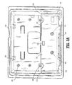
- FIG. 3A shows a front view of the housing with a hinge structure in a retracted position, according to an embodiment of the present invention
- FIG. 3B shows a front view of the housing with the hinge structure in a pivoted position, according to an embodiment of the present invention
- FIGS. 3C-3D show left side views of the housing with the hinge structure in a pivoted position, according to an embodiment of the present invention
- FIG. 3E shows a perspective view of the housing with the hinge structure in a pivoted position according to an embodiment of the present invention
- FIG. 3F shows a rear view of the housing, according to an embodiment of the present invention.
- FIG. 3G shows a bottom view of the housing, according to an embodiment of the present invention.
- FIG. 4A shows a top perspective view of the portable entertainment system including the media unit in a pivoted position with respect to the housing, according to an embodiment of the present invention
- FIG. 4B shows a top view of the portable entertainment system including the media unit in a pivoted position with respect to the housing, according to an embodiment of the present invention
- FIG. 4C shows a left side view of the portable entertainment system including the media unit in a pivoted position with respect to the housing, according to an embodiment of the present invention
- FIG. 4D shows a left side view of the portable entertainment system including the media unit being coupled to or removed from the housing via the hinge structure, according to an embodiment of the present invention
- FIG. 4E shows a close-up left side view of the media unit engaged with the hinge structure, according to an embodiment of the present invention
- FIG. 5A shows a perspective view of a wired connection running from the media unit through the housing, according to an embodiment of the present invention
- FIG. 5B shows a front view of a headrest including a wired connection, according to an embodiment of the present invention
- FIG. 5C shows a close-up view of the wired connection shown in FIG. 5B ;
- FIG. 6A shows a close-up view of a tab for restricting pivoting of the media unit with respect to the housing in the extended position, according to an embodiment of the present invention
- FIG. 6B shows a close-up view of the tab of FIG. 6A in the retracted position, according to an embodiment of the present invention
- FIG. 7A shows a bottom view of a media unit removed from a housing, according to an embodiment of the present invention
- FIG. 7B shows a front view of a housing with a hinge structure in a retracted position, according to an embodiment of the present invention
- FIG. 7C shows a front view of a housing with a hinge structure in a pivoted position, according to an embodiment of the present invention
- FIG. 7D shows a close-up view of the housing and hinge structure shown in FIG. 7C , according to an embodiment of the present invention
- FIG. 7E shows a bottom view of a housing, according to an embodiment of the present invention.
- FIG. 7F shows a close-up view of the housing shown in FIG. 7E , according to an embodiment of the present invention.
- FIG. 8A shows a right side view of a housing, according to an embodiment of the present invention.
- FIG. 8B shows a close-up view of the right inside portion of a housing, according to an embodiment of the present invention.
- FIG. 9A shows a rear view of a media unit removed from a housing, according to an embodiment of the present invention.
- FIG. 9B shows a right side view of a media unit removed from a housing, according to an embodiments of the present invention.
- FIG. 10 is a flow chart showing a method of displaying an entertainment system for a vehicle seat, according to an embodiment of the present invention.
- An entertainment system 100 includes a housing 110 mounted in a headrest 10 of a seat of a vehicle, such as an automobile, minivan or sport utility vehicle (SUV) to provide media, such as video and audio to rear seat passengers.
- a vehicle such as an automobile, minivan or sport utility vehicle (SUV) to provide media, such as video and audio to rear seat passengers.
- the entertainment system and housing may be mounted in a body of seat.
- the entertainment system 100 further includes a media unit 120 that can be easily coupled to and removed from the housing 110 .
- the media unit 120 may be operational when coupled to or removed from the housing.
- a headrest 10 includes an entertainment system 100 mounted therein.
- the entertainment system 100 includes a housing 110 and a media unit 120 , which is easily coupled to and removed from the housing 110 .
- the media unit 120 includes a display 130 having a screen for displaying video.
- the screen is preferably an LCD type display, but may be another type of display, such as, for example, an organic LED, a plasma display or electro-luminescent display.
- an LCD simultaneously displays different content in right and left viewing directions by directionally controlling the viewing angle of the LCD.
- one passenger can see a program from a first media source from a right side of the display, while another can see a program from a second media source from the left side of the display, the simultaneous display of different content on the display (e.g. display 130 ), is accomplished by superimposing a parallax barrier on a thin film transistor (TFT) LCD to enable light from a backlight to separate into right and left directions.
- TFT thin film transistor
- Video is supplied from a media source, for example, a DVD player 140 provided behind the display 130 (see FIG. 4A ).
- the media source may also be, for example, a CD-ROM player, a video game player, a videocassette player, a television tuner, a radio tuner, a wireless receiver, an MP3 player, a digital video recorder, a device for playing media supplied from a portable storage device (e.g., a portable hard drive, memory cards, flash memory sticks, key drives, thumb drives), and/or a device for playing media supplied from a portable audio or video player, such as, for example, an IPOD®.
- the media unit 120 may include a memory device, for example, a DVR, which receives and stores video programming, and hardware for playing such programming.
- the display 130 can be electrically connected to an auxiliary media source trough auxiliary port 142 .
- the display 130 is electrically connected to a media source, for example, another DVD player in another headrest or a media source located elsewhere in the vehicle, such as under a seat, via a wired connection 150 running from the media unit 120 .
- the wired connection 150 running from the media unit 120 preferably includes electrical connectors, for example, pin connectors, for connecting to mating pin connectors 151 positioned in the headrest 10 , which are, in turn, connected to wire leads running through the headrest support rods 15 to connect to a wire harness or distribution box (not shown).
- a user is able to remove the media unit 120 from the housing 110 without cutting or pulling apart the wires.
- the media unit 120 and the housing 110 each include openings 152 , 153 through which wires can be fed.
- the wired connection 150 preferably carries, for example, power, ground, and audio/video inputs outputs.
- video from DVD player 140 may be supplied via wired connection 150 to a display located in another headrest of the vehicle.
- the collection 150 may also carry control signals for a wireless FM modulator for supplying wireless audio to a vehicle sound system or to wireless headphones.
- the front face of the media unit 120 includes a plurality of control buttons, for example, a power button 141 , a screen mode button 143 for controlling aspect ratio, play and stop buttons 145 for controlling play of a video program and a source button 147 for controlling the source of a program (e.g., DVD or auxiliary input).
- a power button 141 for controlling power
- a screen mode button 143 for controlling aspect ratio
- play and stop buttons 145 for controlling play of a video program
- a source button 147 for controlling the source of a program (e.g., DVD or auxiliary input).
- the media unit 120 also includes an infrared transmitter and receiver 146 for transmitting, for example, wireless audio signals to wireless headphones, and for receiving remote control signals.
- a headphone jack 148 is also positioned on the front face of the media unit 120 .
- the media unit 120 includes slits 168 formed in the body thereof, creating openings to facilitate ventilation and the passage of sound from, for example, a speaker (not shown) provided in the body of the media unit 120 .
- the media unit 120 can be operated when the media unit 120 is not positioned in the housing 110 .
- the media unit 110 may receive power by connecting to a specialized battery or battery pack, household batteries and/or an AC/DC adapter.
- the connection between the battery pack and the media unit 120 may be provided through any appropriate electrical contacts, for example, contacts for connecting to Lithium or NiCad batteries.
- the media unit 120 can connect to an AC/DC adapter via an AC/DC adapter port.
- a battery housing in the media unit 120 can be used to receive household batteries or compact battery packs.
- the housing 110 includes a plurality of recesses 160 for receiving fixing devices, such as screws 161 for mounting the housing 110 to a rigid portion of the headrest 10 (see FIG. 5B ).
- the housing 110 also includes a plurality of flexible members 162 which flex upward by pressure from tabs 163 (see FIGS. 2A , 4 A- 4 B) when the media unit 120 is pivoted into the housing 110 . Once the tabs 163 pass the flexible members 162 , the flexible members flex back downward to hold the media unit 120 in place.
- the members 162 flex back upward similar to when the media unit 120 is pivoted into the housing 110 to allow the media unit 120 to freely rotate.
- the housing 110 includes a hinge structure 170 , which pivots the media unit 120 with respect to the housing 110 .
- the hinge structure 170 receives and provides support for the media unit 120 so as to couple the media unit 120 to the housing 110 .
- the hinge structure 170 is formed in a U-shape having a rear side 171 , right and left sides 172 , 173 and a bottom side 174 .
- the hinge structure 170 is coupled to the housing 110 via a hinge 175 .
- the hinge structure 170 includes openings 176 , 177 on the rear and bottom sides 171 , 174 thereof to provide access to fixing devices, such as, screws 161 .
- the hinge structure 170 is made from metal, such as, for example, aluminum, cast iron or stainless steel, but may also be made from, for example, plastic or rubber.
- the media unit 120 is positioned in the hinge structure 170 to rest on the bottom side 174 , such that the rear, right and left sides 171 - 173 partially surround rear, right and left sides of the media unit 120 .
- the right and left sides 172 , 173 of the hinge structure 170 include inward folds 172 a and 173 a , which engage grooves 164 formed on right and left sides of the media unit 120 .
- the engagement of the grooves 164 with the folds 172 a , 173 a secures the media unit 120 in the hinge structure 170 .
- the media unit 120 includes a flexible member 165 on its rear side that fits into an opening 178 on the rear side of the hinge structure 170 to further secure the media unit 120 to the hinge structure 170 .
- the flexible member 165 flexes toward the inside of the media unit 120 when the media unit 120 is being positioned in the hinge structure 170 and flexes back out through opening 178 when the media unit 120 is in place.
- a lip portion 165 a of the flexible member 165 passes through the opening 178 to keep the media unit 120 in place.
- the hinge 175 includes two loops 175 a and 175 b , which rotate around a rod 175 c .
- the hinge structure 170 rotates in the range of approximately 0° to approximately 135°.
- Alternative hinges known to those of ordinary skill in the art may be used and the angle range of rotation may be varied to be greater or smaller depending on design preferences.
- the media unit 120 can be pivoted outward with respect to the housing 110 to adjust a viewing angle of the display 130 and to provide access to a media source 140 to insert or remove a media storage medium, such as, for example, a DVD.
- the media storage medium insertion point 149 and control buttons 144 for the media source 140 can be located on a top side of the media unit 120 .
- the media unit 120 includes a tab 167 that can be gripped by a user to pull the media unit 120 out from a secured position in the housing 110 .
- the tab 167 is positioned at a top center portion of the front face of the media unit 120 .
- the media unit 120 may include a tab 190 on a back side thereof at location 189 that can be extended to engage a curved slot/groove 191 formed in the housing 110 .
- the groove 191 follows the rotation of the media unit 120 with respect to the housing 110 and engagement of the tab 190 with the groove 191 restricts an angle of rotation of media unit 120 in a range of approximately 0° to approximately 45°.
- the tab 190 can be extended or retracted by sliding a handle 192 attached to the tab 190 in opposite lateral directions.
- the tab 190 is not engaged with the groove 191 .
- the media unit 120 can be pivoted to angles greater than about 45°, to, for example, about 90° and about 135° with respect to the housing 110 , as shown in FIG. 4B .
- the hinge structure 170 includes an opening 196 to provide access to handle 192 and an opening 197 through which tab 190 can pass to reach groove 191 .
- a media unit 220 similar to the media unit 120 , includes a connector 250 mounted therein.
- the connector 250 may be a pin connector or any other electrical connector used for transmission of signals, such as audio, video and power signals.
- An opening 252 provides access to the connector 250 , and the connector 250 can be mounted in the media unit 220 by fixing the connector to a portion of a circuit board 255 and attaching the circuit board 255 to the media unit 220 using a fixing device(s) 254 , such as for example, a screw, bolt, or rivet.
- a housing 210 similar to the housing 110 , includes a connector 251 positioned on a circuit board 256 .
- the circuit board 256 is mounted to a bottom side 274 of a hinge structure 270 of the housing 210 .
- the hinge structure 270 is similar to the hinge structure 170 .
- the circuit board 256 may be mounted to the hinge structure 270 using a fixing device(s) 258 , such as, for example, a screw, bolt or rivet, passing through a hole(s) 257 in the circuit board 256 .
- the connector 251 is configured to mate with connector 250 . Therefore, like the connector 250 , the connector 251 may be a pin connector or any other electrical connector used for transmission of signals, such as audio, video and power signals.
- the connector 251 is configured to fit in the opening 252 of the media unit 220 and mates with the connector 250 when the media unit 220 is positioned in the hinge structure 270 .
- a connector or plurality of connectors 259 are positioned on the circuit board 256 at an end of the circuit board opposite the connector 251 .
- the connectors 255 are electrically connected to the connector 251 via the circuit board 256 .
- the connectors 259 are configured to connect to wire leads running through the headrest support rods 15 to connect to a wire harness or distribution box as described above.
- the bottom of the housing 210 includes an opening 253 through which the connectors 259 can be accessed.
- the media unit 220 includes a plurality of holes 281 that receive a plurality of protruding portions 282 positioned on the bottom side 274 of the hinge structure 270 .
- the plurality of protruding portions 282 line up with and fit in the plurality of holes 281 to aid in securing the media unit 220 to the hinge structure 270 .
- the housing 210 includes a plurality of indentations 283 formed on left and right sides thereof.
- the indentations 283 are configured along a cure that, like groove 191 , follows rotation of the media unit 220 with respect to the housing 210 .
- the indentations 283 are designed to receive a tab portion 284 extending from each of right and left sides 272 , 273 of the hinge structure 270 .
- the tab portion 284 is, for example, curved in a “C” shape, and configured to fit into any one of the indentations 283 .
- the combination of the tab portions 284 and the indentations 283 provide for angling the hinge portion 270 , and a media unit 220 positioned therein, at multiple angles with respect to the housing 210 , to, for example, control viewing angle.
- the engagement of the tab portion 284 with an indentation 283 secures the hinge structure 270 at a specific angle with respect to the housing 210 and prevents the hinge structure 270 from rotating forward or backward due to jostling, caused by, for example, movement of the vehicle.
- the media unit 220 like the media unit 120 , includes a flexible member 265 having a lip portion 265 a for passing through an opening 278 in the hinge structure 270 ) and grooves 264 for engaging folds 272 a and 273 a of the hinge structure 270 .
- the grooves 264 include a wide portion 264 a , which facilitates positioning of the grooves 264 to engage the folds 272 a and 273 a.
- the housings 110 or 210 are installed in a replacement headrest for a vehicle.
- a factory headrest is removed and replaced with the replacement headrest including the housing 110 or 210 , which receives the media unit 120 or 220 .
- the dealer When displaying a vehicle at a vehicle dealership, the dealer removes the factory headrest and replaces the factory headrest with a replacement headrest including the housing 110 or 210 .
- the factory headrest is stored in safe place, such as, for example, in the trunk of the vehicle.
- the replacement headrest is removed and the factory headrest is re-installed.
- a dealer may display a media unit that does not have working parts in the housing 110 or 210 .
- the dealer may insert a mock-up media unit in the hinge structures 170 or 270 of the housing 110 or 210 , so as to convey to a purchaser what the media unit will look like without risking damage to an actual media unit 120 or 220 by prospective purchasers visiting the dealership.
- the dealer replaces the mock-up media unit with an actual media unit 120 or 220 , and electrically connects the entertainment system to the vehicle by, for example, running wire leads through the headrest support rods 15 to connect to a wire harness or distribution box (not shown) as described above.
- a consumer may also choose to keep the mock-up and replacement headrest for possible later installation.
- the dealer can sell the vehicle with the factory headrest, the replacement headrest, the mock-up, and an actual media unit 120 or 220 without making the electrical connections to the vehicle.
- the dealer may also provide the factory headrest to a consumer even if the consumer chooses the entertainment system.
- a method of displaying an entertainment system for a vehicle seat is shown.
- a housing 110 or 210 is installed in a replacement headrest (Step 301 )
- a factory headrest is removed from the vehicle and replaced with a replacement headrest (Step 302 )
- a mock-up media unit is installed in the housing 110 or 210 by inserting the mock-up media unit into the hinge structure 170 or 270 (Step 303 ). If a consumer determines that it does not want the seat entertainment system in the vehicle, the process proceeds to Step 304 , whereby the replacement headrest is removed and replaced with the factory headrest.
- Step 305 the mock-up media unit is removed from the housing and replaced with an actual media unit 120 or 220 inserted into the hinge structure 170 or 270 .
- Step 306 the seat entertainment system is electrically connected to the vehicle by, for example, running wire leads through the headrest support rods 15 to connect to a wire harness or distribution box (not shown).
Abstract
Description
Claims (16)
Priority Applications (9)
| Application Number | Priority Date | Filing Date | Title |
|---|---|---|---|
| US11/557,177 US7780231B2 (en) | 2003-05-15 | 2006-11-07 | Entertainment system mountable in a vehicle seat and methods for mounting and displaying same |
| CA2628973A CA2628973C (en) | 2005-11-07 | 2006-11-07 | Entertainment system mountable in a vehicle seat and methods for mounting and displaying same |
| ES06837125.1T ES2451645T3 (en) | 2005-11-07 | 2006-11-07 | Audio-visual system that can be mounted on a vehicle seat and its assembly and visualization procedures |
| PCT/US2006/043432 WO2007056425A2 (en) | 2005-11-07 | 2006-11-07 | Entertainment system mountable in a vehicle seat and methods for mounting and displaying same |
| EP06837125.1A EP1949364B1 (en) | 2005-11-07 | 2006-11-07 | Entertainment system mountable in a vehicle seat and methods for mounting and displaying same |
| US12/862,101 US8520152B2 (en) | 2003-05-15 | 2010-08-24 | Entertainment system mountable in a vehicle and methods for mounting and displaying same |
| US13/945,400 US9210364B2 (en) | 2003-05-15 | 2013-07-18 | Entertainment system mountable in a vehicle and methods for mounting and displaying same |
| US14/960,605 US9815417B2 (en) | 2003-05-15 | 2015-12-07 | Entertainment system mountable in a vehicle and methods for mounting and displaying same |
| US15/812,677 US20180065569A1 (en) | 2003-05-15 | 2017-11-14 | Entertainment system mountable in a vehicle and methods for mounting and displaying same |
Applications Claiming Priority (4)
| Application Number | Priority Date | Filing Date | Title |
|---|---|---|---|
| US10/438,724 US7245274B2 (en) | 2003-05-15 | 2003-05-15 | Headrest mountable video system |
| US10/688,611 US7679578B2 (en) | 2003-05-15 | 2003-10-17 | Headrest mountable video system |
| US73433705P | 2005-11-07 | 2005-11-07 | |
| US11/557,177 US7780231B2 (en) | 2003-05-15 | 2006-11-07 | Entertainment system mountable in a vehicle seat and methods for mounting and displaying same |
Related Parent Applications (1)
| Application Number | Title | Priority Date | Filing Date |
|---|---|---|---|
| US10/688,611 Continuation-In-Part US7679578B2 (en) | 2000-10-27 | 2003-10-17 | Headrest mountable video system |
Related Child Applications (2)
| Application Number | Title | Priority Date | Filing Date |
|---|---|---|---|
| US12/862,101 Continuation-In-Part US8520152B2 (en) | 2003-05-15 | 2010-08-24 | Entertainment system mountable in a vehicle and methods for mounting and displaying same |
| US12/862,101 Continuation US8520152B2 (en) | 2003-05-15 | 2010-08-24 | Entertainment system mountable in a vehicle and methods for mounting and displaying same |
Publications (2)
| Publication Number | Publication Date |
|---|---|
| US20070070192A1 US20070070192A1 (en) | 2007-03-29 |
| US7780231B2 true US7780231B2 (en) | 2010-08-24 |
Family
ID=38023948
Family Applications (1)
| Application Number | Title | Priority Date | Filing Date |
|---|---|---|---|
| US11/557,177 Active 2024-10-31 US7780231B2 (en) | 2003-05-15 | 2006-11-07 | Entertainment system mountable in a vehicle seat and methods for mounting and displaying same |
Country Status (4)
| Country | Link |
|---|---|
| US (1) | US7780231B2 (en) |
| EP (1) | EP1949364B1 (en) |
| ES (1) | ES2451645T3 (en) |
| WO (1) | WO2007056425A2 (en) |
Cited By (17)
| Publication number | Priority date | Publication date | Assignee | Title |
|---|---|---|---|---|
| US20070101372A1 (en) * | 2005-11-02 | 2007-05-03 | Chang Chung L | Headrest mounted entertainment system |
| US20070242172A1 (en) * | 2005-09-16 | 2007-10-18 | Jeff Macholz | Interchangeable switch assembly for media device |
| US20080170165A1 (en) * | 2007-01-16 | 2008-07-17 | Mark Lee | Reception Structure for Mobile Video and Audio Device |
| US20100007805A1 (en) * | 2008-07-11 | 2010-01-14 | Vitito Christopher J | Inductively powered mobile entertainment system |
| US20110156892A1 (en) * | 2009-12-25 | 2011-06-30 | J&K Car Electronics Corporation | On-board equipment and control method thereof |
| US20110272548A1 (en) * | 2010-05-10 | 2011-11-10 | Be Aerospace, Inc. | Video bezel seat attachment |
| US8388060B2 (en) | 2007-04-16 | 2013-03-05 | Chung Lung Chang | Headrest-mounted entertainment systems |
| US8449031B2 (en) | 2005-11-02 | 2013-05-28 | Chung Lung Chang | Headrest-mounted entertainment systems |
| US20130259261A1 (en) * | 2010-12-14 | 2013-10-03 | Voxx International Corporation | Vehicle entertainment system |
| US8585140B2 (en) | 2002-08-14 | 2013-11-19 | Chung L. Chang | Headrest-mounted monitor |
| US8783767B2 (en) | 2011-05-06 | 2014-07-22 | David Wood | Headrest media system for a seat back of a vehicle |
| US9421892B1 (en) * | 2015-01-29 | 2016-08-23 | Toyota Motor Engineering & Manufacturing North America, Inc. | Headrest with retainer |
| US10099591B2 (en) * | 2016-12-01 | 2018-10-16 | David Flynn | Dual configuration headrest system |
| US10556549B2 (en) | 2015-07-08 | 2020-02-11 | Voxx International Corporation | Headrest-integrated entertainment system |
| US20200296847A1 (en) * | 2019-03-15 | 2020-09-17 | Panasonic Avionics Corporation | Systems and methods for monitor attachment |
| US10793038B2 (en) | 2015-09-22 | 2020-10-06 | Voxx International Corporation | Headrest integrated entertainment system |
| US10814796B2 (en) | 2018-02-12 | 2020-10-27 | Panasonic Avionics Corporation | Systems and methods for providing quick release of video monitors from an assembly |
Families Citing this family (12)
| Publication number | Priority date | Publication date | Assignee | Title |
|---|---|---|---|---|
| US6871356B2 (en) | 2002-10-28 | 2005-03-22 | Johnson Safety, Inc. | Mobile video system |
| US8953102B2 (en) * | 2006-01-04 | 2015-02-10 | Voxx International Corporation | Vehicle entertainment tablet unit and cradle |
| US20080108247A1 (en) * | 2006-11-06 | 2008-05-08 | Jeff Macholz | Headrest entertainment system |
| US8141948B2 (en) * | 2007-05-11 | 2012-03-27 | Audiovox Corporation | Seat back entertainment system |
| US8369082B2 (en) * | 2010-08-04 | 2013-02-05 | Savant Systems, Llc | In-wall dock for a tablet computer |
| US8659889B2 (en) * | 2011-05-20 | 2014-02-25 | Apple Inc. | Docking station for providing digital signage |
| US20130107449A1 (en) * | 2011-10-28 | 2013-05-02 | Yuan Zi Su | Tablet computer enclosure |
| WO2015126762A1 (en) | 2014-02-20 | 2015-08-27 | Dirtt Environmental Solutions Inc. | Method of configuring walls |
| WO2016149362A1 (en) | 2015-03-16 | 2016-09-22 | Dirtt Environmental Solutions, Inc. | Glass panel reconfigurable wall panels |
| US11240922B2 (en) * | 2016-06-10 | 2022-02-01 | Dirtt Environmental Solutions Ltd. | Wall system with electronic device mounting assembly |
| CA2997014A1 (en) | 2016-06-10 | 2017-12-14 | Patrick Harris | Glass substrates with touchscreen technology |
| CA3030282A1 (en) | 2016-07-08 | 2018-01-11 | Dirtt Environmental Solutions, Inc. | Low-voltage smart glass |
Citations (102)
| Publication number | Priority date | Publication date | Assignee | Title |
|---|---|---|---|---|
| US3019050A (en) * | 1960-02-15 | 1962-01-30 | Aerotec Ind Inc | Aircraft seats and aircraft seating |
| US4647980A (en) | 1986-01-21 | 1987-03-03 | Aviation Entertainment Corporation | Aircraft passenger television system |
| US4681366A (en) | 1984-07-02 | 1987-07-21 | Irvin Industries, Inc. | Vanity mirror or vehicle accessory assembly and mounting apparatus therefor |
| US4702519A (en) | 1984-07-02 | 1987-10-27 | Irvin Industries, Inc. | Vanity mirror |
| US4756528A (en) | 1986-07-24 | 1988-07-12 | Ramon Umashankar | Video system for passenger vehicles |
| US4836478A (en) | 1987-10-15 | 1989-06-06 | Ergotron, Inc. | Suspension system for personal computers and monitors |
| US4843477A (en) | 1986-11-25 | 1989-06-27 | Toyoda Gosei Co., Ltd. | Vehicle television receiver system |
| US4982996A (en) | 1989-02-17 | 1991-01-08 | Fiat Auto S.P.A. | Automotive seating system featuring a television set |
| US5021922A (en) | 1988-11-30 | 1991-06-04 | International Business Machines Corporation | Portable personal computer |
| US5214514A (en) | 1989-08-07 | 1993-05-25 | Ottmar Haberkern | Compact video/sound apparatus with foldable screen |
| US5255214A (en) | 1992-09-11 | 1993-10-19 | Ma Hsi Kuang | Portable computer with a level and angular position adjustable LCD assembly |
| US5267775A (en) | 1991-10-03 | 1993-12-07 | B/E Avionics, Inc. | System for mounting a monitor |
| US5335076A (en) | 1992-10-16 | 1994-08-02 | General Production Services, Inc. | Soft shroud for screen display device |
| US5396340A (en) | 1990-10-01 | 1995-03-07 | Sony Corporation | Optical disc reproducing apparatus having displaying made control key functions |
| US5410447A (en) | 1990-04-27 | 1995-04-25 | Kabushiki Kaisha Toshiba | Portable computer comprising keyboard and coordinate input tablet connected by two perpendicularly arranged hinges |
| US5463688A (en) * | 1994-05-19 | 1995-10-31 | Motorola | Telephone mounting receptacle having opposed retractable latch members |
| US5507556A (en) * | 1994-11-04 | 1996-04-16 | Burns Aerospace Corporation | Seat including an automatically adjustable display screen assembly |
| US5555466A (en) | 1994-10-12 | 1996-09-10 | Asa Electronics Corporation | Vehicular audio/visual system having distribution box for connecting individual passenger monitors to multiple program sources |
| US5610822A (en) | 1995-03-03 | 1997-03-11 | Trimble Navigation, Ltd. | Position-related multi-media presentation system |
| US5667179A (en) * | 1994-09-30 | 1997-09-16 | Rosen; John B. | Ratcheting articulable monitor support and presentation device |
| US5793413A (en) | 1995-05-01 | 1998-08-11 | Bell Atlantic Network Services, Inc. | Wireless video distribution |
| US5796575A (en) | 1992-12-21 | 1998-08-18 | Hewlett-Packard Company | Portable computer with hinged cover having a window |
| US5842715A (en) * | 1996-12-20 | 1998-12-01 | Jones; Christopher A. | Vehicular entertainment system |
| US5949345A (en) | 1997-05-27 | 1999-09-07 | Microsoft Corporation | Displaying computer information to a driver of a vehicle |
| US6081420A (en) | 1996-10-01 | 2000-06-27 | Samsung Electronics Co., Ltd. | LCD display apparatus |
| US6092705A (en) | 1998-08-03 | 2000-07-25 | Meritt; Ronald R. | Self-contained case for housing transporting and mounting video monitor and video player for use in passenger vehicles |
| US6098705A (en) | 1998-06-30 | 2000-08-08 | Daewoo Electronics Co., Ltd. | Coil type condenser for refrigerator |
| US6102476A (en) | 1998-03-11 | 2000-08-15 | May; Gordon G. | Computer furniture with integrated computer |
| US6134223A (en) | 1996-09-18 | 2000-10-17 | Motorola, Inc. | Videophone apparatus, method and system for audio and video conferencing and telephony |
| US6199810B1 (en) * | 1997-10-14 | 2001-03-13 | Sony Video Taiwan, Co., Ltd. | Flat-panel display assembly mountable in a vehicle |
| USD438853S1 (en) | 1999-12-27 | 2001-03-13 | Kabushiki Kaisha Toshiba | Digital videodisk player |
| US6216927B1 (en) | 1998-08-03 | 2001-04-17 | Ronald Meritt | Mounting system for releasably and securely mounting an entertainment accessory within an automobile |
| US20010001083A1 (en) | 1999-06-25 | 2001-05-10 | Helot Jacques H. | Docking station for multiple devices |
| US6266236B1 (en) | 1997-08-27 | 2001-07-24 | Vadem | Apparatus and method for connecting and articulating display in a portable computer having multiple display orientations |
| US6292236B1 (en) | 1999-03-26 | 2001-09-18 | Rosen Products Llc | Automotive-ceiling-mounted monitor |
| US6301367B1 (en) | 1995-03-08 | 2001-10-09 | Interval Research Corporation | Wearable audio system with acoustic modules |
| US6300880B1 (en) | 1996-01-16 | 2001-10-09 | Philips Electronics North America Corp. | Multichannel audio distribution system having portable receivers |
| US6317039B1 (en) | 1998-10-19 | 2001-11-13 | John A. Thomason | Wireless video audio data remote system |
| US6337913B1 (en) | 1999-03-16 | 2002-01-08 | Keng-Yuan Chang | Wireless transmitter/receiver circuit system with floating frequency tracing function for a wireless audio equipment |
| US6339455B1 (en) | 1999-12-29 | 2002-01-15 | William L. Allan | Digital video disc vehicle television |
| US20020005897A1 (en) | 2000-07-11 | 2002-01-17 | Kim Kyung Wook | Apparatus for controlling angle of AV front panel for automobile |
| US20020024538A1 (en) | 1998-11-18 | 2002-02-28 | Bandaru M. Krishna | Digital media frame |
| US6380978B1 (en) | 1997-10-06 | 2002-04-30 | Dvdo, Inc. | Digital video system and methods for providing same |
| FR2817812A1 (en) | 2000-12-12 | 2002-06-14 | Faurecia Sieges Automobile | Seat for motor vehicle has seat squab with backrest having casing containing video display screen |
| US6409242B1 (en) | 2000-11-14 | 2002-06-25 | Chung L. Chang | Flat thin screen T/V monitor automotive roof mount |
| US6419379B1 (en) | 1999-11-04 | 2002-07-16 | Federal-Mogul World Wide, Inc. | Vehicle center console with interior illumination |
| US6443574B1 (en) | 2001-07-24 | 2002-09-03 | Visteon Global Technologies, Inc. | Removable vehicle entertainment system |
| WO2002074577A1 (en) | 2001-03-21 | 2002-09-26 | Security Vision Concept | Head rest, particularly for a motor vehicle seat |
| US20020149905A1 (en) | 2001-04-11 | 2002-10-17 | Jackson, Louiss R. | Flat hanging computer |
| US20020159270A1 (en) | 2001-01-23 | 2002-10-31 | Lynam Niall R. | Vehicular lighting system |
| US20020186531A1 (en) | 2001-06-12 | 2002-12-12 | Himanshu Pokharna | Mobile computer system with detatchable thermoelectric module for enhanced cooling capability in a docking station |
| US20030021086A1 (en) | 2001-07-24 | 2003-01-30 | Landry Christian C. | Multifunctional foldable computer |
| US20030042378A1 (en) * | 2001-09-05 | 2003-03-06 | Honda Giken Kogyo Kabushiki Kaisha | In-vehicle monitor support structure |
| US20030057749A1 (en) | 2001-09-24 | 2003-03-27 | Buono Robert A. | Video seating system for a vehicle |
| FR2829980A1 (en) | 2001-09-26 | 2003-03-28 | Security Vision Concept | Method for mounting e.g. games console in back of seat head rest comprises fitting it on to head rest cover and then fitted into mounting in back of rest so that cover is sandwiched between it and mounting |
| US20030111880A1 (en) | 2001-12-19 | 2003-06-19 | Guy Lambiaso | Incorporation of connexion connectivity to a preexisting communication infrastructure |
| US20030117728A1 (en) | 1999-11-24 | 2003-06-26 | Donnelly Corporation, A Corporation Of The State Of Michigan | Interior rearview mirror system including a pendent accessory |
| US6587127B1 (en) | 1997-11-25 | 2003-07-01 | Motorola, Inc. | Content player method and server with user profile |
| US20030137584A1 (en) | 2001-10-29 | 2003-07-24 | Gene Norvell | Detachable vehicle monitor |
| US20030193619A1 (en) | 2002-04-11 | 2003-10-16 | Toby Farrand | System and method for speculative tuning |
| US20030194968A1 (en) | 2002-04-15 | 2003-10-16 | Young Steven Jay | System and method for local modulation and distribution of stored audio content |
| US20030198008A1 (en) | 2002-04-18 | 2003-10-23 | Gateway, Inc. | Computer having detachable wireless independently operable computer |
| US20030220091A1 (en) | 2002-04-11 | 2003-11-27 | Digeo, Inc. | System and method for speculative tuning |
| US20030229897A1 (en) | 2000-04-07 | 2003-12-11 | Live Tv, Inc. | Aircraft in-flight entertainment system providing passenger specific advertisements, and associated methods |
| US6665163B2 (en) | 2000-03-01 | 2003-12-16 | International Business Machines Corporation | Method for controlling fan in computer system |
| US6666492B1 (en) | 2002-12-20 | 2003-12-23 | Lear Corporation | Vehicle instrument panel assembly |
| US6669285B1 (en) | 2002-07-02 | 2003-12-30 | Eric Park | Headrest mounted video display |
| US20040032541A1 (en) | 2002-08-13 | 2004-02-19 | Sohail Rochel | Universal vehicle headrest monitor supporting bracket assembly |
| US6717798B2 (en) | 2001-03-22 | 2004-04-06 | Intel Corporation | Docking digital picture displays |
| US6719343B2 (en) | 2001-03-22 | 2004-04-13 | Lear Corporation | Vehicle console assembly |
| US6724317B1 (en) | 2000-03-29 | 2004-04-20 | Mitsubishi Denki Kabushiki Kaisha | Audiovisual player system |
| US20040085485A1 (en) | 2002-11-05 | 2004-05-06 | Audiovox Corporation | Mobile video system |
| US6739654B1 (en) | 2003-04-24 | 2004-05-25 | Hexa-Chain Co., Ltd. | Headrest-mount display mounting structure |
| US6754070B2 (en) | 2002-03-15 | 2004-06-22 | E-Lead Electronic Co., Ltd. | Car use computer |
| US20040130616A1 (en) | 2003-01-03 | 2004-07-08 | Thomas Tseng | Flip-open screen with audio/video player |
| US20040224638A1 (en) | 2003-04-25 | 2004-11-11 | Apple Computer, Inc. | Media player system |
| US20040227696A1 (en) | 2003-05-15 | 2004-11-18 | Audiovox Corporation | Headrest mountable video system |
| US6871356B2 (en) | 2002-10-28 | 2005-03-22 | Johnson Safety, Inc. | Mobile video system |
| US20050099547A1 (en) | 2003-11-07 | 2005-05-12 | Vitito Christopher J. | Automobile entertainment system |
| US20050110313A1 (en) * | 2003-11-07 | 2005-05-26 | Vitito Christopher J. | Housing for an automobile entertainment system |
| US6899365B2 (en) | 2003-05-15 | 2005-05-31 | Audiovox Corporation | Seat mountable entertainment system |
| EP1550583A1 (en) | 2003-12-30 | 2005-07-06 | Hexa-Chain Co., Ltd | View angle-adjustable detachable display assembly |
| US20050204596A1 (en) | 2004-03-18 | 2005-09-22 | Peng Juen T | Portable seat back display |
| US20050242637A1 (en) | 2003-11-07 | 2005-11-03 | Vitito Christopher J | Vehicle entertainment system with a side loading DVD player |
| US20050242636A1 (en) | 2003-11-07 | 2005-11-03 | Vitito Christopher J | Vehicle entertainment system with a rear loading DVD player |
| US20050242638A1 (en) | 2003-11-07 | 2005-11-03 | Vitito Christopher J | Vehicle entertainment system with backside loading DVD player |
| US6979038B1 (en) | 2003-09-15 | 2005-12-27 | Ktv Usa, Inc. | Video monitor hinge assembly |
| USD515522S1 (en) | 2004-04-19 | 2006-02-21 | Vitito Christopher J | Entertainment system for an automobile headrest |
| US20060047426A1 (en) | 2003-11-07 | 2006-03-02 | Vitito Christopher J | Vehicle entertainment system |
| US7036879B2 (en) | 2002-08-14 | 2006-05-02 | Johnson Safety, Inc. | Headrest-mounted monitor |
| US20060098403A1 (en) | 2004-03-08 | 2006-05-11 | Originatic Llc | Electronic device having a movable input assembly with multiple input sides |
| US7044546B2 (en) | 2002-08-14 | 2006-05-16 | Johnson Safety, Inc. | Headrest-mounted monitor |
| US20060112144A1 (en) | 2001-11-16 | 2006-05-25 | Sigmatel, Inc. | Remote-directed management of media content |
| US20060109388A1 (en) | 1998-12-28 | 2006-05-25 | Johnson Controls Technology Company | Wireless signal system for a video display unit |
| US7084932B1 (en) | 1999-12-28 | 2006-08-01 | Johnson Controls Technology Company | Video display system for a vehicle |
| US20070047198A1 (en) | 2005-08-24 | 2007-03-01 | Apple Computer, Inc. A California Corporation | Docking station for hand held electronic devices |
| US20070057541A1 (en) | 2005-09-12 | 2007-03-15 | Fu-Ruei Huang | Angle-adjusting apparatus for a housing of headrest display |
| US7201354B1 (en) | 2003-12-24 | 2007-04-10 | Ktv Usa, Inc. | Video monitor mounting system |
| US7201356B2 (en) | 2004-05-07 | 2007-04-10 | Kai-Cheng Huang | Mounting apparatus of displayer suitable for external installation and inset installation |
| US20070101039A1 (en) | 2005-11-02 | 2007-05-03 | Dei Headquarters, Inc. | Versatile docking station for portable electronic devices |
| US20070247800A1 (en) | 2004-03-08 | 2007-10-25 | Originatic Llc | Assembly having a main unit and a mounting unit |
| US20080170165A1 (en) * | 2007-01-16 | 2008-07-17 | Mark Lee | Reception Structure for Mobile Video and Audio Device |
Family Cites Families (1)
| Publication number | Priority date | Publication date | Assignee | Title |
|---|---|---|---|---|
| US7245274B2 (en) * | 2003-05-15 | 2007-07-17 | Audiovox Corporation | Headrest mountable video system |
-
2006
- 2006-11-07 ES ES06837125.1T patent/ES2451645T3/en active Active
- 2006-11-07 EP EP06837125.1A patent/EP1949364B1/en not_active Not-in-force
- 2006-11-07 WO PCT/US2006/043432 patent/WO2007056425A2/en active Application Filing
- 2006-11-07 US US11/557,177 patent/US7780231B2/en active Active
Patent Citations (110)
| Publication number | Priority date | Publication date | Assignee | Title |
|---|---|---|---|---|
| US3019050A (en) * | 1960-02-15 | 1962-01-30 | Aerotec Ind Inc | Aircraft seats and aircraft seating |
| US4681366A (en) | 1984-07-02 | 1987-07-21 | Irvin Industries, Inc. | Vanity mirror or vehicle accessory assembly and mounting apparatus therefor |
| US4702519A (en) | 1984-07-02 | 1987-10-27 | Irvin Industries, Inc. | Vanity mirror |
| US4647980A (en) | 1986-01-21 | 1987-03-03 | Aviation Entertainment Corporation | Aircraft passenger television system |
| US4647980B1 (en) | 1986-01-21 | 1989-06-13 | ||
| US4756528A (en) | 1986-07-24 | 1988-07-12 | Ramon Umashankar | Video system for passenger vehicles |
| US4843477A (en) | 1986-11-25 | 1989-06-27 | Toyoda Gosei Co., Ltd. | Vehicle television receiver system |
| US4836478A (en) | 1987-10-15 | 1989-06-06 | Ergotron, Inc. | Suspension system for personal computers and monitors |
| US5021922A (en) | 1988-11-30 | 1991-06-04 | International Business Machines Corporation | Portable personal computer |
| US4982996A (en) | 1989-02-17 | 1991-01-08 | Fiat Auto S.P.A. | Automotive seating system featuring a television set |
| US5214514A (en) | 1989-08-07 | 1993-05-25 | Ottmar Haberkern | Compact video/sound apparatus with foldable screen |
| US5410447A (en) | 1990-04-27 | 1995-04-25 | Kabushiki Kaisha Toshiba | Portable computer comprising keyboard and coordinate input tablet connected by two perpendicularly arranged hinges |
| US5396340A (en) | 1990-10-01 | 1995-03-07 | Sony Corporation | Optical disc reproducing apparatus having displaying made control key functions |
| US5267775A (en) | 1991-10-03 | 1993-12-07 | B/E Avionics, Inc. | System for mounting a monitor |
| US5255214A (en) | 1992-09-11 | 1993-10-19 | Ma Hsi Kuang | Portable computer with a level and angular position adjustable LCD assembly |
| US5335076A (en) | 1992-10-16 | 1994-08-02 | General Production Services, Inc. | Soft shroud for screen display device |
| US5796575A (en) | 1992-12-21 | 1998-08-18 | Hewlett-Packard Company | Portable computer with hinged cover having a window |
| US5463688A (en) * | 1994-05-19 | 1995-10-31 | Motorola | Telephone mounting receptacle having opposed retractable latch members |
| US5667179A (en) * | 1994-09-30 | 1997-09-16 | Rosen; John B. | Ratcheting articulable monitor support and presentation device |
| US5555466A (en) | 1994-10-12 | 1996-09-10 | Asa Electronics Corporation | Vehicular audio/visual system having distribution box for connecting individual passenger monitors to multiple program sources |
| US5507556A (en) * | 1994-11-04 | 1996-04-16 | Burns Aerospace Corporation | Seat including an automatically adjustable display screen assembly |
| US5610822A (en) | 1995-03-03 | 1997-03-11 | Trimble Navigation, Ltd. | Position-related multi-media presentation system |
| US6301367B1 (en) | 1995-03-08 | 2001-10-09 | Interval Research Corporation | Wearable audio system with acoustic modules |
| US5793413A (en) | 1995-05-01 | 1998-08-11 | Bell Atlantic Network Services, Inc. | Wireless video distribution |
| US6300880B1 (en) | 1996-01-16 | 2001-10-09 | Philips Electronics North America Corp. | Multichannel audio distribution system having portable receivers |
| US6134223A (en) | 1996-09-18 | 2000-10-17 | Motorola, Inc. | Videophone apparatus, method and system for audio and video conferencing and telephony |
| US6081420A (en) | 1996-10-01 | 2000-06-27 | Samsung Electronics Co., Ltd. | LCD display apparatus |
| US5842715A (en) * | 1996-12-20 | 1998-12-01 | Jones; Christopher A. | Vehicular entertainment system |
| US5949345A (en) | 1997-05-27 | 1999-09-07 | Microsoft Corporation | Displaying computer information to a driver of a vehicle |
| US6266236B1 (en) | 1997-08-27 | 2001-07-24 | Vadem | Apparatus and method for connecting and articulating display in a portable computer having multiple display orientations |
| US6380978B1 (en) | 1997-10-06 | 2002-04-30 | Dvdo, Inc. | Digital video system and methods for providing same |
| US6199810B1 (en) * | 1997-10-14 | 2001-03-13 | Sony Video Taiwan, Co., Ltd. | Flat-panel display assembly mountable in a vehicle |
| US6587127B1 (en) | 1997-11-25 | 2003-07-01 | Motorola, Inc. | Content player method and server with user profile |
| US6102476A (en) | 1998-03-11 | 2000-08-15 | May; Gordon G. | Computer furniture with integrated computer |
| US6098705A (en) | 1998-06-30 | 2000-08-08 | Daewoo Electronics Co., Ltd. | Coil type condenser for refrigerator |
| US6092705A (en) | 1998-08-03 | 2000-07-25 | Meritt; Ronald R. | Self-contained case for housing transporting and mounting video monitor and video player for use in passenger vehicles |
| US6216927B1 (en) | 1998-08-03 | 2001-04-17 | Ronald Meritt | Mounting system for releasably and securely mounting an entertainment accessory within an automobile |
| US6317039B1 (en) | 1998-10-19 | 2001-11-13 | John A. Thomason | Wireless video audio data remote system |
| US20020024538A1 (en) | 1998-11-18 | 2002-02-28 | Bandaru M. Krishna | Digital media frame |
| US20060109388A1 (en) | 1998-12-28 | 2006-05-25 | Johnson Controls Technology Company | Wireless signal system for a video display unit |
| US6337913B1 (en) | 1999-03-16 | 2002-01-08 | Keng-Yuan Chang | Wireless transmitter/receiver circuit system with floating frequency tracing function for a wireless audio equipment |
| US6292236B1 (en) | 1999-03-26 | 2001-09-18 | Rosen Products Llc | Automotive-ceiling-mounted monitor |
| US20010001083A1 (en) | 1999-06-25 | 2001-05-10 | Helot Jacques H. | Docking station for multiple devices |
| US6419379B1 (en) | 1999-11-04 | 2002-07-16 | Federal-Mogul World Wide, Inc. | Vehicle center console with interior illumination |
| US20030117728A1 (en) | 1999-11-24 | 2003-06-26 | Donnelly Corporation, A Corporation Of The State Of Michigan | Interior rearview mirror system including a pendent accessory |
| USD438853S1 (en) | 1999-12-27 | 2001-03-13 | Kabushiki Kaisha Toshiba | Digital videodisk player |
| US7084932B1 (en) | 1999-12-28 | 2006-08-01 | Johnson Controls Technology Company | Video display system for a vehicle |
| US6339455B1 (en) | 1999-12-29 | 2002-01-15 | William L. Allan | Digital video disc vehicle television |
| US6665163B2 (en) | 2000-03-01 | 2003-12-16 | International Business Machines Corporation | Method for controlling fan in computer system |
| US6724317B1 (en) | 2000-03-29 | 2004-04-20 | Mitsubishi Denki Kabushiki Kaisha | Audiovisual player system |
| US20030229897A1 (en) | 2000-04-07 | 2003-12-11 | Live Tv, Inc. | Aircraft in-flight entertainment system providing passenger specific advertisements, and associated methods |
| US20020005897A1 (en) | 2000-07-11 | 2002-01-17 | Kim Kyung Wook | Apparatus for controlling angle of AV front panel for automobile |
| US6409242B1 (en) | 2000-11-14 | 2002-06-25 | Chung L. Chang | Flat thin screen T/V monitor automotive roof mount |
| US7379125B2 (en) | 2000-11-14 | 2008-05-27 | Chang Chung L | Flat thin screen TV/monitor automotive roof mount |
| FR2817812A1 (en) | 2000-12-12 | 2002-06-14 | Faurecia Sieges Automobile | Seat for motor vehicle has seat squab with backrest having casing containing video display screen |
| US20020159270A1 (en) | 2001-01-23 | 2002-10-31 | Lynam Niall R. | Vehicular lighting system |
| WO2002074577A1 (en) | 2001-03-21 | 2002-09-26 | Security Vision Concept | Head rest, particularly for a motor vehicle seat |
| US6719343B2 (en) | 2001-03-22 | 2004-04-13 | Lear Corporation | Vehicle console assembly |
| US6717798B2 (en) | 2001-03-22 | 2004-04-06 | Intel Corporation | Docking digital picture displays |
| US20020149905A1 (en) | 2001-04-11 | 2002-10-17 | Jackson, Louiss R. | Flat hanging computer |
| US20020186531A1 (en) | 2001-06-12 | 2002-12-12 | Himanshu Pokharna | Mobile computer system with detatchable thermoelectric module for enhanced cooling capability in a docking station |
| US20030021086A1 (en) | 2001-07-24 | 2003-01-30 | Landry Christian C. | Multifunctional foldable computer |
| US6443574B1 (en) | 2001-07-24 | 2002-09-03 | Visteon Global Technologies, Inc. | Removable vehicle entertainment system |
| US20030042378A1 (en) * | 2001-09-05 | 2003-03-06 | Honda Giken Kogyo Kabushiki Kaisha | In-vehicle monitor support structure |
| US6758521B2 (en) | 2001-09-05 | 2004-07-06 | Honda Giken Kogyo Kabushiki Kaisha | In-vehicle monitor support structure |
| US20030057749A1 (en) | 2001-09-24 | 2003-03-27 | Buono Robert A. | Video seating system for a vehicle |
| US20030184137A1 (en) | 2001-09-26 | 2003-10-02 | Gilbert Jost | Method for assembling a case on a cushion, protection cover fitted with case and cushion fitted with such cover |
| FR2829980A1 (en) | 2001-09-26 | 2003-03-28 | Security Vision Concept | Method for mounting e.g. games console in back of seat head rest comprises fitting it on to head rest cover and then fitted into mounting in back of rest so that cover is sandwiched between it and mounting |
| US20030137584A1 (en) | 2001-10-29 | 2003-07-24 | Gene Norvell | Detachable vehicle monitor |
| US20060112144A1 (en) | 2001-11-16 | 2006-05-25 | Sigmatel, Inc. | Remote-directed management of media content |
| US20030111880A1 (en) | 2001-12-19 | 2003-06-19 | Guy Lambiaso | Incorporation of connexion connectivity to a preexisting communication infrastructure |
| US6754070B2 (en) | 2002-03-15 | 2004-06-22 | E-Lead Electronic Co., Ltd. | Car use computer |
| US20030220091A1 (en) | 2002-04-11 | 2003-11-27 | Digeo, Inc. | System and method for speculative tuning |
| US20030193619A1 (en) | 2002-04-11 | 2003-10-16 | Toby Farrand | System and method for speculative tuning |
| US20030194968A1 (en) | 2002-04-15 | 2003-10-16 | Young Steven Jay | System and method for local modulation and distribution of stored audio content |
| US20030198008A1 (en) | 2002-04-18 | 2003-10-23 | Gateway, Inc. | Computer having detachable wireless independently operable computer |
| US20040007906A1 (en) | 2002-07-02 | 2004-01-15 | Eric Park | Headrest mounted video display |
| US6669285B1 (en) | 2002-07-02 | 2003-12-30 | Eric Park | Headrest mounted video display |
| US20040032541A1 (en) | 2002-08-13 | 2004-02-19 | Sohail Rochel | Universal vehicle headrest monitor supporting bracket assembly |
| US7070237B2 (en) | 2002-08-13 | 2006-07-04 | Epsilon Electronics, Inc. | Universal vehicle headrest monitor supporting bracket assembly |
| US7036879B2 (en) | 2002-08-14 | 2006-05-02 | Johnson Safety, Inc. | Headrest-mounted monitor |
| US7044546B2 (en) | 2002-08-14 | 2006-05-16 | Johnson Safety, Inc. | Headrest-mounted monitor |
| US6871356B2 (en) | 2002-10-28 | 2005-03-22 | Johnson Safety, Inc. | Mobile video system |
| US20040085485A1 (en) | 2002-11-05 | 2004-05-06 | Audiovox Corporation | Mobile video system |
| US6666492B1 (en) | 2002-12-20 | 2003-12-23 | Lear Corporation | Vehicle instrument panel assembly |
| US20040130616A1 (en) | 2003-01-03 | 2004-07-08 | Thomas Tseng | Flip-open screen with audio/video player |
| US6739654B1 (en) | 2003-04-24 | 2004-05-25 | Hexa-Chain Co., Ltd. | Headrest-mount display mounting structure |
| US20040224638A1 (en) | 2003-04-25 | 2004-11-11 | Apple Computer, Inc. | Media player system |
| US6899365B2 (en) | 2003-05-15 | 2005-05-31 | Audiovox Corporation | Seat mountable entertainment system |
| US20040227696A1 (en) | 2003-05-15 | 2004-11-18 | Audiovox Corporation | Headrest mountable video system |
| US6979038B1 (en) | 2003-09-15 | 2005-12-27 | Ktv Usa, Inc. | Video monitor hinge assembly |
| US20050242636A1 (en) | 2003-11-07 | 2005-11-03 | Vitito Christopher J | Vehicle entertainment system with a rear loading DVD player |
| US20050110313A1 (en) * | 2003-11-07 | 2005-05-26 | Vitito Christopher J. | Housing for an automobile entertainment system |
| US20050099547A1 (en) | 2003-11-07 | 2005-05-12 | Vitito Christopher J. | Automobile entertainment system |
| US7360833B2 (en) | 2003-11-07 | 2008-04-22 | Vitito Christopher J | Vehicle entertainment system with backside loading DVD player |
| US20050242638A1 (en) | 2003-11-07 | 2005-11-03 | Vitito Christopher J | Vehicle entertainment system with backside loading DVD player |
| US20050242637A1 (en) | 2003-11-07 | 2005-11-03 | Vitito Christopher J | Vehicle entertainment system with a side loading DVD player |
| US20060047426A1 (en) | 2003-11-07 | 2006-03-02 | Vitito Christopher J | Vehicle entertainment system |
| US20060148575A1 (en) | 2003-11-07 | 2006-07-06 | Vitito Christopher J | Automobile entertainment system |
| US7201354B1 (en) | 2003-12-24 | 2007-04-10 | Ktv Usa, Inc. | Video monitor mounting system |
| EP1550583A1 (en) | 2003-12-30 | 2005-07-06 | Hexa-Chain Co., Ltd | View angle-adjustable detachable display assembly |
| US20070247800A1 (en) | 2004-03-08 | 2007-10-25 | Originatic Llc | Assembly having a main unit and a mounting unit |
| US20060098403A1 (en) | 2004-03-08 | 2006-05-11 | Originatic Llc | Electronic device having a movable input assembly with multiple input sides |
| US20050204596A1 (en) | 2004-03-18 | 2005-09-22 | Peng Juen T | Portable seat back display |
| USD515522S1 (en) | 2004-04-19 | 2006-02-21 | Vitito Christopher J | Entertainment system for an automobile headrest |
| US7201356B2 (en) | 2004-05-07 | 2007-04-10 | Kai-Cheng Huang | Mounting apparatus of displayer suitable for external installation and inset installation |
| US20070047198A1 (en) | 2005-08-24 | 2007-03-01 | Apple Computer, Inc. A California Corporation | Docking station for hand held electronic devices |
| US20070057541A1 (en) | 2005-09-12 | 2007-03-15 | Fu-Ruei Huang | Angle-adjusting apparatus for a housing of headrest display |
| US20070101039A1 (en) | 2005-11-02 | 2007-05-03 | Dei Headquarters, Inc. | Versatile docking station for portable electronic devices |
| US20080170165A1 (en) * | 2007-01-16 | 2008-07-17 | Mark Lee | Reception Structure for Mobile Video and Audio Device |
Non-Patent Citations (18)
| Title |
|---|
| International Search Report dated Jun. 5, 2009 for PCT Application No. PCT/US200643300. |
| International Search Report from corresponding PCT Application No. PCT/US2006/43432. |
| International Search Report from PCT/US2004/34371. |
| Notice of Allowance and Fee(s) Due from corresponding U.S. Appl. No. 10/438,724, now U.S. Patent No. 7,245,275. |
| Office Action dated Aug. 24, 2009 for U.S. Appl. No. 11/649,121. |
| Office Action dated Dec. 24, 2009 for U.S. Appl. No. 11/072,171. |
| Office Action dated Mar. 16, 2010 for U.S. Appl. No. 11/649,121. |
| Office Action dated Oct. 6, 2009 for U.S. Appl. No. 11/593,380. |
| Office Action mailed Feb. 26, 2008 from U.S. Appl. No. 11/072,171. |
| Office Action mailed Jan. 10, 2007 from corresponding U.S. Appl. No. 10/438,724, now U.S. Patent No. 7,245,275. |
| Office Action mailed Jul. 13, 2007 from corresponding U.S. Appl. No. 10/688,611. |
| Office Action mailed Jun. 16, 2006 from corresponding U.S. Appl. No. 10/688,611. |
| Office Action mailed Jun. 5, 2006 from corresponding U.S. Appl. No. 10/438,724, now U.S. Patent No. 7,245,275. |
| Office Action mailed Mar. 11, 2009 from corresponding U.S. Appl. No. 11/072,171. |
| Office Action mailed Oct. 27, 2006 from corresponding U.S. Appl. No. 10/388,611. |
| Office Action mailed Oct. 4, 2005 from corresponding U.S. Appl. No.,10/438,724, now U.S. Patent No. 7,245,275. |
| Office Action mailed Sep. 12, 2008 from U.S. Appl. No. 11/072,171. |
| Office Action mailed Sep. 22, 2008 from U.S. Appl. No. 10/808,659. |
Cited By (27)
| Publication number | Priority date | Publication date | Assignee | Title |
|---|---|---|---|---|
| US10421411B2 (en) | 2002-08-14 | 2019-09-24 | Voxx International Corporation | Headrest-mounted monitor |
| US9340133B2 (en) | 2002-08-14 | 2016-05-17 | Johnson Safety, Inc. | Headrest-mounted monitor |
| US8585140B2 (en) | 2002-08-14 | 2013-11-19 | Chung L. Chang | Headrest-mounted monitor |
| US20070242172A1 (en) * | 2005-09-16 | 2007-10-18 | Jeff Macholz | Interchangeable switch assembly for media device |
| US8400572B2 (en) * | 2005-09-16 | 2013-03-19 | Voxx International Corporation | Interchangeable switch assembly for media device |
| US9004588B2 (en) | 2005-11-02 | 2015-04-14 | Johnson Safety, Inc | Headrest-mounted entertainment systems |
| US20070101372A1 (en) * | 2005-11-02 | 2007-05-03 | Chang Chung L | Headrest mounted entertainment system |
| US8449031B2 (en) | 2005-11-02 | 2013-05-28 | Chung Lung Chang | Headrest-mounted entertainment systems |
| US20080170165A1 (en) * | 2007-01-16 | 2008-07-17 | Mark Lee | Reception Structure for Mobile Video and Audio Device |
| US8388060B2 (en) | 2007-04-16 | 2013-03-05 | Chung Lung Chang | Headrest-mounted entertainment systems |
| US20100007805A1 (en) * | 2008-07-11 | 2010-01-14 | Vitito Christopher J | Inductively powered mobile entertainment system |
| US8203657B2 (en) * | 2008-07-11 | 2012-06-19 | Audiovox Corporation | Inductively powered mobile entertainment system |
| US20110156892A1 (en) * | 2009-12-25 | 2011-06-30 | J&K Car Electronics Corporation | On-board equipment and control method thereof |
| US20110272548A1 (en) * | 2010-05-10 | 2011-11-10 | Be Aerospace, Inc. | Video bezel seat attachment |
| US9731660B2 (en) * | 2010-12-14 | 2017-08-15 | Voxx International Corporation | Vehicle entertainment system |
| US20160023619A1 (en) * | 2010-12-14 | 2016-01-28 | Voxx International Corporation | Vehicle entertainment system |
| US9150164B2 (en) * | 2010-12-14 | 2015-10-06 | Voxx International Corporation | Vehicle entertainment system |
| US20130259261A1 (en) * | 2010-12-14 | 2013-10-03 | Voxx International Corporation | Vehicle entertainment system |
| US8783767B2 (en) | 2011-05-06 | 2014-07-22 | David Wood | Headrest media system for a seat back of a vehicle |
| US9421892B1 (en) * | 2015-01-29 | 2016-08-23 | Toyota Motor Engineering & Manufacturing North America, Inc. | Headrest with retainer |
| US10556549B2 (en) | 2015-07-08 | 2020-02-11 | Voxx International Corporation | Headrest-integrated entertainment system |
| US10793038B2 (en) | 2015-09-22 | 2020-10-06 | Voxx International Corporation | Headrest integrated entertainment system |
| US10099591B2 (en) * | 2016-12-01 | 2018-10-16 | David Flynn | Dual configuration headrest system |
| US10814796B2 (en) | 2018-02-12 | 2020-10-27 | Panasonic Avionics Corporation | Systems and methods for providing quick release of video monitors from an assembly |
| US20200296847A1 (en) * | 2019-03-15 | 2020-09-17 | Panasonic Avionics Corporation | Systems and methods for monitor attachment |
| CN111692464A (en) * | 2019-03-15 | 2020-09-22 | 松下航空电子公司 | System and method for monitor attachment |
| US10834837B2 (en) * | 2019-03-15 | 2020-11-10 | Panasonic Avionics Corporation | Systems and methods for monitor attachment |
Also Published As
| Publication number | Publication date |
|---|---|
| US20070070192A1 (en) | 2007-03-29 |
| EP1949364B1 (en) | 2014-01-08 |
| EP1949364A4 (en) | 2012-07-04 |
| WO2007056425A2 (en) | 2007-05-18 |
| WO2007056425A3 (en) | 2007-07-26 |
| EP1949364A2 (en) | 2008-07-30 |
| ES2451645T3 (en) | 2014-03-28 |
Similar Documents
| Publication | Publication Date | Title |
|---|---|---|
| US7780231B2 (en) | Entertainment system mountable in a vehicle seat and methods for mounting and displaying same | |
| US9815417B2 (en) | Entertainment system mountable in a vehicle and methods for mounting and displaying same | |
| US7791586B2 (en) | Entertainment system mountable in a vehicle seat | |
| US7909397B2 (en) | In-vehicle docking station for a portable media player | |
| US7149078B2 (en) | Video display system | |
| US8162395B2 (en) | Automobile entertainment system | |
| EP1854298B1 (en) | Headrest mountable video system | |
| US8201203B2 (en) | Headrest mounted vehicle entertainment system with an integrated cooling system | |
| CA2636137C (en) | In-vehicle docking station for a portable media player | |
| US8562056B2 (en) | Audio apparatus for vehicle | |
| US20060288378A1 (en) | Vehicle entertainment system with quick service disconnect from headrest | |
| CA2628973C (en) | Entertainment system mountable in a vehicle seat and methods for mounting and displaying same | |
| EP1949677B1 (en) | Entertainment system mountable in a vehicle seat | |
| KR20050008173A (en) | a remote controller custody structure of an audio/video system for an automobile | |
| CA2811991C (en) | In-vehicle docking station for a portable media player | |
| JP2005041441A (en) | Cradle and on-vehicle device provided with cradle | |
| JPH0720792A (en) | Display device |
Legal Events
| Date | Code | Title | Description |
|---|---|---|---|
| AS | Assignment |
Owner name: AUDIOVOX CORPORATION, NEW YORK Free format text: ASSIGNMENT OF ASSIGNORS INTEREST;ASSIGNOR:SHALAM, DAVID M.;REEL/FRAME:018489/0541 Effective date: 20061105 |
|
| AS | Assignment |
Owner name: AUDIOVOX CORPORATION, NEW YORK Free format text: ASSIGNMENT OF ASSIGNORS INTEREST;ASSIGNORS:SHALAM, DAVID M.;SCHEDIVY, GEORGE C.;REEL/FRAME:018805/0303 Effective date: 20070115 |
|
| STCF | Information on status: patent grant |
Free format text: PATENTED CASE |
|
| AS | Assignment |
Owner name: WELLS FARGO CAPITAL FINANCE, LLC, AS AGENT, NEW YO Free format text: SECURITY AGREEMENT;ASSIGNORS:AUDIOVOX CORPORATION;AUDIOVOX ELECTRONICS CORPORATION;CODE SYSTEMS, INC.;AND OTHERS;REEL/FRAME:026587/0906 Effective date: 20110301 |
|
| AS | Assignment |
Owner name: CODE SYSTEMS, INC., MICHIGAN Free format text: RELEASE BY SECURED PARTY;ASSIGNOR:WELLS FARGO CAPITAL FINANCE, LLC;REEL/FRAME:027864/0905 Effective date: 20120309 Owner name: VOXX INTERNATIONAL CORPORATION, NEW YORK Free format text: RELEASE BY SECURED PARTY;ASSIGNOR:WELLS FARGO CAPITAL FINANCE, LLC;REEL/FRAME:027864/0905 Effective date: 20120309 Owner name: KLIPSH GROUP INC., INDIANA Free format text: RELEASE BY SECURED PARTY;ASSIGNOR:WELLS FARGO CAPITAL FINANCE, LLC;REEL/FRAME:027864/0905 Effective date: 20120309 Owner name: AUDIOVOX ELECTRONICS CORPORATION, NEW YORK Free format text: RELEASE BY SECURED PARTY;ASSIGNOR:WELLS FARGO CAPITAL FINANCE, LLC;REEL/FRAME:027864/0905 Effective date: 20120309 Owner name: TECHNUITY, INC., INDIANA Free format text: RELEASE BY SECURED PARTY;ASSIGNOR:WELLS FARGO CAPITAL FINANCE, LLC;REEL/FRAME:027864/0905 Effective date: 20120309 |
|
| AS | Assignment |
Owner name: WELLS FAGO BANK, NATIONAL ASSOCIATION, NORTH CAROL Free format text: SECURITY AGREEMENT;ASSIGNOR:VOXX INTERNATIONAL CORPORATION;REEL/FRAME:027890/0319 Effective date: 20120314 |
|
| FPAY | Fee payment |
Year of fee payment: 4 |
|
| MAFP | Maintenance fee payment |
Free format text: PAYMENT OF MAINTENANCE FEE, 8TH YEAR, LARGE ENTITY (ORIGINAL EVENT CODE: M1552) Year of fee payment: 8 |
|
| MAFP | Maintenance fee payment |
Free format text: PAYMENT OF MAINTENANCE FEE, 12TH YEAR, LARGE ENTITY (ORIGINAL EVENT CODE: M1553); ENTITY STATUS OF PATENT OWNER: LARGE ENTITY Year of fee payment: 12 |