US7787442B2 - Communication statistic information collection apparatus - Google Patents
Communication statistic information collection apparatus Download PDFInfo
- Publication number
- US7787442B2 US7787442B2 US11/049,128 US4912805A US7787442B2 US 7787442 B2 US7787442 B2 US 7787442B2 US 4912805 A US4912805 A US 4912805A US 7787442 B2 US7787442 B2 US 7787442B2
- Authority
- US
- United States
- Prior art keywords
- flow
- statistics
- information
- packet
- entry
- Prior art date
- Legal status (The legal status is an assumption and is not a legal conclusion. Google has not performed a legal analysis and makes no representation as to the accuracy of the status listed.)
- Active, expires
Links
Images


Classifications
-
- H—ELECTRICITY
- H04—ELECTRIC COMMUNICATION TECHNIQUE
- H04L—TRANSMISSION OF DIGITAL INFORMATION, e.g. TELEGRAPHIC COMMUNICATION
- H04L43/00—Arrangements for monitoring or testing data switching networks
-
- H—ELECTRICITY
- H04—ELECTRIC COMMUNICATION TECHNIQUE
- H04L—TRANSMISSION OF DIGITAL INFORMATION, e.g. TELEGRAPHIC COMMUNICATION
- H04L45/00—Routing or path finding of packets in data switching networks
- H04L45/60—Router architectures
-
- H—ELECTRICITY
- H04—ELECTRIC COMMUNICATION TECHNIQUE
- H04L—TRANSMISSION OF DIGITAL INFORMATION, e.g. TELEGRAPHIC COMMUNICATION
- H04L43/00—Arrangements for monitoring or testing data switching networks
- H04L43/08—Monitoring or testing based on specific metrics, e.g. QoS, energy consumption or environmental parameters
- H04L43/0876—Network utilisation, e.g. volume of load or congestion level
- H04L43/0894—Packet rate
Definitions
- the present invention relates to a communication statistic information collection apparatus and, more particularly, to a communication statistic information collection apparatus to be connected as a node apparatus to a communication network to collect statistics information, such as the number of packets and the number of bytes, individually for each of packet flows.
- the Internet has established its position as an important social infrastructure and begun to be applied not only to conventional Best-Effort based data communication but also to data communication which requires quality assurance of communication of data including real time data such as voice or video data and transaction data for basic industries.
- data communication including real time data such as voice or video data and transaction data for basic industries.
- ADSL Asymmetric Digital Subscriber Line
- FTTH Fiber To The Home
- communication services enterprises such as carriers and ISPs (Internet Service Providers) require a network monitoring function for collecting and analyzing statistics information such as an amount of data communication to recognize the state of communication over a network.
- ISPs Internet Service Providers
- a network monitoring function for collecting and analyzing statistics information such as an amount of data communication to recognize the state of communication over a network.
- a flow group of communication data which is classified according to the source and destination of data, an application, quality level, and the like.
- flow-by-flow statistics information allows the carriers and the ISPs to check the state of quality assurance of communication at the time of providing a quality-assured communication service.
- traffic engineering hereinafter abbreviated as TE
- TE traffic engineering
- provisioning which systematically prepares network resources by estimating customer demands and promptly provides the network resources in response to requests from users for communication bands, services, and the like, the detection and analysis of an attack to network resources from an unauthorized user, billing, and the like.
- the statistic information collecting function is normally provided in a communication node apparatus, which controls packet transfer over a network, such as a router, a switch, or the like.
- Non-Patent Document 1 As a method for collecting flow statistics information, a cache-type flow statistics technology described in, e.g., a publication entitled “NetFlow Overview”., Cisco Systems, Technical Marketing Internet Technologies Division, February 2003PP 1 - 109 (Non-Patent Document 1) has been known.
- a statistic information collection system using the above conventional technology is comprised of a plurality of statistic information collection apparatus arranged in distributed relation over a network and a collector apparatus which analyzes traffic over the entire network based on statistics information reported periodically from these statistic information collection apparatus.
- the router having the cache-type statistic information collecting function is provided with a flow table for identifying a flow to which a received packet belongs and searches, every time a packet is received, the flow table by using a searching key composed of a combination of the header information items of the received packet, the input line interface number of the packet, and the like.
- the flow table is composed of a plurality of flow entries prepared for individual flows.
- Each of the flow entries defines a flow identification condition by a combination of, e.g., a source IP address, a destination IP address, a protocol type, aTOS (Type of Service) value, a source TCP (Transmission Control Protocol)/UDP (User Datagram Protocol) port number, a destination TCP/UDP port number, an input line interface number, and the like.
- a source IP address e.g., a source IP address, a destination IP address, a protocol type, aTOS (Type of Service) value, a source TCP (Transmission Control Protocol)/UDP (User Datagram Protocol) port number, a destination TCP/UDP port number, an input line interface number, and the like.
- a source IP address e.g., a source IP address, a destination IP address, a protocol type, aTOS (Type of Service) value, a source TCP (Transmission Control Protocol)/UDP (User Datagram Protocol) port number, a destination T
- statistics data such as the number of packets and the number of bytes is updated in the statistics information entry prepared in association with the flow identification condition.
- a new flow entry including, as the flow identification condition, the combination of the header information items, the input interface number, and the like serving as the searching key is added to the flow table.
- the contents of the statistics information entries are periodically monitored and the contents of the statistics information entry in which, e.g., the statistics data has remained unchanged for a certain time or longer are transmitted as statistics information data to the collector apparatus.
- the statistics information entry that has already been reported to the collector apparatus and the flow entry corresponding thereto are deleted from the table by an aging process.
- each router selectively transfers a copy of a received packet to a collector apparatus where a flow is identified from the copy packet and collection and analysis of statistics information are performed.
- Each of the routers composing the sampling-type statistic information collection system samples the received packets in accordance with a sampling rate set preliminarily by a network administrator and transfers the copies (copy packets) of the received packets that have been sampled to the collector apparatus in a prescribed encapsulation format.
- each of the encapsulated packets includes additional information for flow identification such as, e.g., the input line interface number of the received packet, an output line interface number specified from the header information of the received packet, and the IP address (Next Hop IP address) of the router to be the next transfer destination.
- the collector apparatus extracts the copy packet from the encapsulated packet transferred from the router, identifies the flow based on the header information of the copy packet and information for flow identification added as required, and updates the flow-by-flow statistics information.
- flow identification condition information necessary for flow identification accounts for about 200 to 600 bits.
- a searching method using a CAM Content Addressable Memory
- the CAM method enables high-speed matching of a bit pattern indicative of the flow identification condition registered in the memory with a bit pattern given as the searching key.
- the CAM is higher in per-bit cost than a normal semiconductor memory, the problem is encountered that, when the number of flow entries in each of the routers is increased as in the conventional cache-type statistic information collection system, numerous CAM chips are required to constitute the flow table and router cost becomes high.
- the conventional cache-type statistic information collection system can use only the roughly fixed combination of header information items as the flow identification condition, it becomes difficult to use information factors other than the information items described above, e.g., a TCP flag for identifying a control packet type in a TCP connection, a destination MAC (Media Access Control) address and a source MAC address in an Ethernet header, a VLAV (Virtual LAN) identifier for identifying a virtual LAN, and the like for flow identification.
- a TCP flag for identifying a control packet type in a TCP connection
- VLAV Virtual LAN
- sampling-type statistic information collection system flow identification is performed at the collector apparatus so that flow classification using header information in a higher protocol layer, which is impossible with the cache type wherein flow identification is performed at the router, and the collection of statistics information based on the analysis of the content of packet data are enabled.
- sampling type it can also be specified whether sampling for generating a copy packet should be performed for each of the input line interfaces of the received packets. This allows the enhancement of the accuracy of flow statistics by, e.g., limiting packets for which statistics information is to be collected to the packets received from a specified input line.
- Another object of the present invention is to provide a communication statistic information collection apparatus capable of flexible registration of a flow identification entry in a flow table for a packet flow having a preliminarily specified attribute.
- Still another object of the present invention is to provide a communication statistic information collection apparatus capable of selective use of a cache-type statistic information collecting function or a sampling-type statistic information collecting function depending on a packet flow.
- a statistic information collection apparatus includes: a flow table composed of a plurality of flow entries each defining a flow identification condition for identifying a packet flow; a statistics function control table including, at least one statistics control entry defining, in association with a flow identification condition, statistics control information for limiting the packets for which the statistics information is to be collected; and a searching unit for searching, by using a combination of a plurality of header information items extracted from a header of each of the packets received over a network as a flow searching key, the flow table and the statistics function control table for an entry having the flow identification condition corresponding to the flow searching key, wherein the searching unit executes searching the flow table in accordance with the flow searching key generated from the header information of each of the received packets and searching the statistics function control table when there is no flow entry corresponding to the flow searching key, and collecting, when the statistics control entry corresponding to the flow searching key is found from the statistics function control table as a result of searching, the statistics information of a packet flow
- One characteristic aspect of the present invention resides in that, when the statistics control entry is found as the entry corresponding to the flow searching key, the searching unit changes the contents of the flow table or the statistics function control table in accordance with the statistics control information shown by the statistics control entry.
- the statistics control entry specifies, as the flow identification condition, a header information value of at least one of the plurality of header information items serving as the flow searching key which is to be provided in the packet for which the statistics information is collected.
- the statistics function control table described above is combined with the flow table in order to search the table at higher-speed. In this case, when the flow entry corresponding to the flow searching key is not found, the statistics control information entry corresponding to the flow searching key can be found as a result of searching the flow table.
- the statistic information collection apparatus further includes a statistics information table composed of a plurality of statistics information entries for storing statistics information each of which is prepared in association with each of the entries in the flow table and the statistics function control table, wherein the searching unit includes a statistics information processing unit for updating the statistics information in response to packet reception in the statistics information entry corresponding to the flow entry or the statistics control entry found as a result of searching with the flow searching key.
- the statistics function control table (or the flow table) includes a first statistics control entry including, as a part of the statistics control information, a registration flag indicating to register a new flow entry to the flow table
- the statistic information collection apparatus further includes an entry management unit for adding a new entry to the flow table when the first statistics control entry is found as the entry corresponding to the flow searching key as a result of searching performed by the searching unit.
- the new flow entry includes the combination of the plurality of header information items extracted from the header of the received packets as the flow identification condition, so that the statistics information is individually collected for each of the packet flows specified by the flow searching key.
- the statistic function control table (or the flow table) includes a second statistics control entry defining the statistics control information which indicates to generate a copy of each of the received packets in the packet flow corresponding to the flow identification condition at a specified sampling rate and, when the second statistics control entry is found as the entry corresponding to the flow searching key, the searching unit starts a control operation for generating the copy of the received packet corresponding to the flow identification condition and transferring the copy packet to a specified statistic information collection apparatus.
- the second statistics control entry includes, as a part of the statistics control information, a condition for starting sampling to transfer a copy of the received packet generated at a specified sampling rate to a preliminarily specified statistics information collection apparatus and a sampling flag indicative of whether the sampling should be executed
- the searching unit comprises: a sampling determination unit for comparing, when the second statistics control entry is found as the entry corresponding to the flow searching key and the sampling flag is in an OFF state, the condition for starting the sampling with the statistics information shown by the statistics information entry corresponding to the second statistics control entry and changing the sampling flag to an ON state when the condition for starting the sampling is satisfied; and a sampling unit for issuing a control signal to generate the copy of the received packet at the specified sampling rate when the sampling flag is in the ON state.
- the second control entry includes, as a part of the statistics control information, a condition for ending the sampling.
- the sampling unit compares the condition for ending the sampling with the statistics information shown by the statistics information entry corresponding to the second control entry and returns the sampling flag to the OFF state when the condition for ending the sampling is satisfied.
- the conditions for starting and ending the sampling are specified by, e.g., a bandwidth value of the packet flow.
- the communication statistic information collection apparatus comprises: a flow table searching unit for searching, by using a combination of a plurality of header information items extracted from a header of each of packets received from the network as a flow searching key, a flow table for a flow entry or a statistics control entry having a flow identification condition corresponding to the flow searching key; a statistics information processing unit for collecting statistics information individually for each of the packet flows in a statistics information entry corresponding to the entry found by the flow table searching unit; a statistics information notification packet generation unit for generating a packet for notifying a preliminarily specified statistic information collection apparatus of the statistics information stored in a statistics information table; and a copy generation unit for generating a copy of the received packet to be transferred to the preliminarily specified statistic information collection apparatus at a specified sampling rate in accordance with statistics control information shown by the specified flow entry found by the flow table searching unit as a result of searching.
- One characteristic aspect of the communication statistic information collection apparatus resides in an entry management unit for adding, when the statistics control entry is found as the entry corresponding to the flow searching key as a result of searching performed by the flow table searching unit, a new flow entry having the contents of the flow searching key as the flow identification condition to the flow table in accordance with the statistics control information shown by the entry.
- the statistics information is supplied to the statistics information notification packet generation unit by the entry management unit.
- the entry management unit monitors a state change in the statistics information table, detects one of the statistics information entries in which the statistics information has remained unchanged for a period longer than a specified time, reads out the statistics information shown by the statistics information entry and the flow identification condition corresponding to the statistics information entry from the statistics information table and the flow table, respectively, and supplies the statistics information and the flow identification condition to the statistics information notification packet generation unit.
- the entry management unit selects a flow entry to be deleted from the flow table as required, reads out the flow identification condition shown by the selected flow entry and the statistics information shown by the statistics information entry corresponding to the selected flow entry from the flow table and the statistics information table, respectively, and supplies the flow identification condition and the read statistics information to the statistics information notification packet generation unit.
- the present invention can designate the flow identification condition to be defined by each of the flow entries as a combination of, e.g., in addition to the header information items extracted from the IP header of each of the received packets, the header information items extracted from the layer 4 header such as a TCP header or a UDP header and from the layer 2 header such as an Ethernet header, and the input line number and output line number of each of the received packets.
- the type of the packet flow for which statistics information is to be collected can be limited by using the statistics control information shown by the statistics control entries. This successfully suppresses an increase in the number of flow entries registered in the flow table. Accordingly, a small capacity is sufficient for a high-speed memory required by the flow table and the cost of the apparatus can be reduced.
- the configuration of the present invention allows selective execution of cache-type statistic information collection and sampling-type statistic information collection by using the statistics control information of the statistics control entries. Further, it allows the specification of conditions for generating a copy packet to be transferred to the collector apparatus for the sampling-type statistic information collection. For example, by specifying the bandwidth value showing the condition for starting sampling as a part of the statistics control information in one of the statistics control entries using the attribute of a specified packet flow to be monitored as the flow identification condition, it becomes possible to start the sampling of the received packet at the time at which the bandwidth of the specified packet flow reaches the starting condition and start the transfer of the copy packet to the collector apparatus.
- the storage of the statistics information in the collector apparatus can be facilitated and the accuracy of analysis can be enhanced.
- This also enables automatic detection and analysis of a packet flow having a characteristic traffic pattern such as data on an attack to a specified server or virus data. This further enables effective use of the resources of the network and the collector apparatus.
- FIG. 1 is a view showing an example of a communication network to which a statistic information collection apparatus according to the present invention is applied;
- FIG. 2 is a view showing the format of a packet communicated over the communication network of FIG. 1 ;
- FIG. 3 is a view showing a header format for an Ethernet V2 frame
- FIG. 4 is a view showing a header format for an Ethernet V2 frame compliant with Tag VLAN
- FIG. 5 is a view showing a header format for an IPv4 packet
- FIG. 6 is a view showing a header format for an IPv6 packet
- FIG. 7 is a view showing a TCP header format
- FIG. 8 is a view showing in detail the TCP flag 133 in FIG. 7 ;
- FIG. 9 is a view showing a format for a UDP header
- FIG. 10 is a view showing an example of a flow identification condition applied to the router R 1 of FIG. 1 ;
- FIG. 11 is a view showing an example of statistics information collected by the router R 1 of FIG. 1 ;
- FIG. 12 is a structural view showing an embodiment of the router R 1 having a statistic collecting function according to the present invention.
- FIG. 13 is a view showing an example of the connecting relationship between the router R 1 and the management terminal 1300 according to the present invention.
- FIG. 14 is a view showing another example of the connecting relationship between the router R 1 and the management terminal 1300 according to the present invention.
- FIG. 15 is a view showing an example of a format for an internal packet processed in the router according to the present invention.
- FIG. 16 is a block diagram showing an example of the received packet processing unit 20 of FIG. 12 ;
- FIG. 17 is a view showing an example of a packet data management information block 200 stored in the memories 25 A and 25 B of FIG. 16 ;
- FIG. 18 is a view showing the relationship between the packet data management information block stored in the storage 25 A (or 25 B) of FIG. 16 and a data block stored in the memory 24 ;
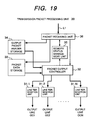
- FIG. 19 is a block diagram showing an example of the transmission packet processing unit 30 of FIG. 16 ;
- FIG. 20 is a block diagram showing an example of the searching unit 40 of FIG. 16 ;
- FIG. 21 is a view showing an example of the flow table 60 of FIG. 16 ;
- FIG. 22 is a view showing an example of the statistic information table 70 of FIG. 16 ;
- FIG. 23 is a view showing an example of a searching result notification 480 outputted from the searching result output unit 48 of FIG. 20 ;
- FIG. 24 is a view showing an example of the address release control table 280 provided in the copy management unit 28 of FIG. 16 ;
- FIG. 25 is a view showing an example of the flow management table 49 of FIG. 20 ;
- FIG. 26 is a view showing a format for a statistics information notification packet 300 outputted from the statistics information notification packet generation unit 53 of FIG. 20 ;
- FIG. 27 is a view for illustrating another embodiment of the flow table 60 shown in FIG. 12 ;
- FIG. 28 is a view for illustrating another embodiment of the statistic information table 70 shown in FIG. 12 .
- FIG. 1 shows an example of a network structure to which the communication statistic information collection apparatus according to the present invention is applied.
- a network shown here is comprised of: a router R 1 accommodating terminals T 1 , T 2 , T 3 , and T 4 ; a router R 2 accommodating a server S 1 ; a router R 3 accommodating a server S 2 ; and a collector apparatus C 1 for collecting statistics information which is connected to the router R 1 .
- the router R 1 has a function as the communication statistic information collection apparatus according to the present invention.
- the terminals T 1 , T 2 , T 3 , and T 4 are connected to the router R 1 via respective lines C-T 1 , C-T 2 , C-T 3 , and C-T 4 and the router R 1 is connected to the routers R 2 and R 3 via the respective lines C-R 2 and C-R 3 .
- the terminals T 1 and T 3 are in communication with the server S 1
- the terminals T 2 and T 4 are in communication with the server S 2
- the respective flows of IP (Internet Protocol) packets transmitted from the server S 1 to the terminals T 1 and T 3 are referred to as “Flow 1 ” and “Flow 2 ”
- the respective flows of IP packets transmitted from the server S 2 to the terminals T 2 and T 4 are referred to as “Flow 3 ” and “Flow 4 ”.
- the flow 1 is composed of a sequence of packets in each of which a higher layer IP protocol is TCP, TOS (Type of Service) in the IP header is TOS 1 , and a source port number and a destination port number in the TCP header are SPRT 1 and DPRT 1 , respectively
- the flow 2 is composed of a sequence of packets in each of which the higher layer IP protocol is TCP, TOS is TOS 1 , the source port number and the destination port number are SPRT 1 and DPRT 3 , respectively
- the flow 3 is composed of a sequence of packets in each of which the higher layer IP protocol is UDP
- TOS is TOS 2
- the source port number and the destination port number in a UDP header are SPRT 2 and DPRT 2
- the flow 4 is composed of packets in each of which the higher layer IP protocol is UDP
- TOS is TOS 2
- the source port number and the destination port number are SPRT 2 and DPRT 4 , respectively.
- FIG. 2 shows a structure of an IP packet 10 communicated over the network described above.
- the IP packet 10 is composed of a header in a plurality of layers compliant with the protocol layers of an OSI (Open System Interconnection) reference model and a data portion.
- the IP packet 10 is composed of a layer 2 header 11 , a layer 3 header 12 , a layer 4 header 13 , and data 14 .
- a protocol such as, e.g., Ethernet, ATM (Asynchronous Transfer Mode), or MPLS (Multi-Protocol Label Switching) can be used.
- a protocol such as, e.g., IP version 4 (IPv4) or IP version 6 (IPv6) can be used.
- IPv4 IP version 4
- IPv6 IP version 6
- TCP Transmission Control Protocol
- UDP User Datagram Protocol
- FIG. 3 shows the header structure of an Ethernet V2 frame as an example of the layer 2 header 11 .
- a preamble/SFD 111 indicative of the beginning of a frame
- a destination terminal address (destination MAC address) 112 and a transmitter address (source MAC address) 113 each in the layer 2 are set.
- FIG. 4 shows the header structure of an Ethernet V2 frame compliant with Tag VLAN as another example of the layer 2 header 11 .
- the preamble/SFD 111 indicative of the beginning of the frame
- the destination terminal address (destination MAC address) 112 and the transmitter address (source MAC address) 113 each in the layer 2
- a TAG protocol ID 114 indicative of compliance with Tag VLAN
- a priority 115 indicative the transfer priority of the frame
- a CFI (Cannonical Field Indicator) 116 indicative of that routing information in the layer 2 is stored
- VLAN ID VLAN identifier
- type 118 indicative of the protocol of the layer 3
- FIG. 5 shows an IPv4 header structure as an example of the layer 3 header 12 .
- An IPv4 header includes a ToS 121 indicative of the quality of packet transfer, a protocol 122 indicative of the protocol of the layer 4, a source IP address 126 A, a destination IP address 127 A, and other information.
- Each of the ToS and the protocol is composed of 8 bits, while each of the source IP address and the destination IP address is composed of 32 bits.
- FIG. 6 shows an IPv6 header structure as another example of the layer 3 header 12 .
- An IPv6 header includes a class 123 indicative of the quality of packet transfer, a next header number 125 indicative of the type of a next header subsequent to the IPv6 header portion, a source IP address 126 B, a destination IP address 127 B, and other information.
- the next header is, e.g., a TCP or UDP header
- a value indicative of the protocol of the layer 4 is set as the next header number 125 .
- Each of the class 123 and the next header number is composed of 8 bits, while each of the source IP address and the destination IP address is composed of 128 bits.
- FIG. 7 shows a TCP header structure as an example of the layer 4 header 13 .
- the TCP header includes, as logical port numbers for the identification of an application in the higher layer, a source port number 131 A and a destination port number 132 A each having a 16-bit length.
- a TCP flag 133 indicative of a packet type in a TCP connection and other information are also included in the TCP header.
- the TCP flag 133 is composed of six flags which are: an urgent flag (URG) 1331 indicating urgent passage of data received at a receiver terminal to an application; an ACK 1332 notifying a transmitter terminal of the reception of data at the receiver terminal; a PUSH 1333 indicating the passage of data without delay between the transmitter terminal and the receiver terminal; an RST 1334 indicating the resetting of a TCP connection; a FIN 1335 indicating the completion of a connection; and an SYN 1336 indicating the establishment of a connection.
- UMG urgent flag
- ACK 1332 notifying a transmitter terminal of the reception of data at the receiver terminal
- a PUSH 1333 indicating the passage of data without delay between the transmitter terminal and the receiver terminal
- RST 1334 indicating the resetting of a TCP connection
- a FIN 1335 indicating the completion of a connection
- SYN 1336 indicating the establishment of a connection.
- FIG. 9 shows an UDP header structure as another example of the layer 4 header 13 .
- the UDP header includes a source port number 131 B and a destination port number 132 B each having a 16-bit length, similarly to the TCP header.
- FIG. 10 shows a part of a flow table defining identification conditions for flows for which statistics information is to be collected in the router R 1 of FIG. 1 .
- the flows for which statistic information is to be collected are limited to packet flows each using TCP as the protocol of the layer 4.
- Each entry in the flow table shows a flow identification condition 62 and statistics control information not shown in association with a flow entry number 61 .
- the flow identification condition 62 is defined by a source IP address 621 , a destination IP address 622 , a higher layer protocol 623 , and a TOS 624 each shown by an IP header and by the respective values of the source port number 625 and the destination port number 626 included in a TCP or UDP header.
- the combination of the header information items shown here is only exemplary of the flow identification condition and the flow identification condition may also be a combination of header information items different from that shown in FIG. 10 .
- a searching unit 40 dynamically performs the registration and deletion of an entry in and from the flow table and partial correction of the contents of the entries. If the entries registered in the flow table are limited to those of TCP, it follows that the router R 1 registers, out of the packet flows received from the lines C-R 2 and CR- 3 , only the flows 1 and 2 in each of which the higher layer protocol is TCP.
- FIG. 11 shows an example of statistic information collected in the statistics information table of the router R 1 .
- the statistics information table is composed of a plurality of statistics information entries corresponding to the flow entry number 61 of the flow table.
- the number of received packets in each of the flows (hereinafter referred to as the number of packets) 721 , the cumulative number of bytes of the received packets (hereinafter referred to as the number of bytes) 722 , the input line number 723 of the received packets, an output line number 724 as the transfer destination of the received packet, and other information 729 are collected as statistics information 72 .
- FIG. 12 is a block diagram showing an example of the router R 1 having the statistic information collecting function according to the present invention.
- the flow table 60 serves also as a statistics function control table storing therein statistics control entries.
- the controller 90 is connected to a management terminal 1300 and sets various parametric information to the received packet processing unit 20 , the searching unit 40 , and the transmission packet processing unit 30 in response to an instruction from the management terminal 1300 .
- the router R 1 may also have a structure in which the received packet processing unit 20 , the transmission packet processing unit 30 , the searching unit 40 , and the controller 90 that have been described above are composed of individual dedicated LSIs and these dedicated LSIs are connected to each other, or a structure in which a plurality of processing units are implemented in a single dedicated LSI so that a smaller number of dedicated LSIs are connected to each other for a reduction in the number of wires between the LSIs.
- a general-purpose MPU Micro Processing Unit
- NP Network Processor
- FIG. 12 shows a structure in which the received packet processing unit 20 and the transmission packet processing unit 30 are connected by a signal line L 1
- the apparatus may also be constructed such that each of the received packet processing unit 20 and the transmission packet processing unit 30 is composed of a plurality of units, and the received packet processing units and the transmission packet processing units are connected by a cross-bar switch.
- a memory for the flow table 60 to be referred to by the searching unit 40 a CAM or an SSRAM, e.g., may be used appropriately when high-speed search performance is required or a DRAM which is low in per-bit cost and small in per-bit chip area can be used appropriately when relatively low-speed search performance satisfies the requirement.
- FIG. 13 shows an example of the management terminal 1300 connected to the controller 90 of the router R 1 .
- the management terminal 1300 is comprised of a display screen 1301 for displaying the contents of various tables in the router R 1 and input means such as a mouse 1302 or a keyboard 1303 for selecting and editing an arbitrary portion of the contents of the table displayed on the display screen.
- FIG. 15 shows an example of a format for an internal packet to be transferred in the router R 1 .
- the internal packet has a structure in which an internal header 15 is added to the head of a packet received from the network shown in FIG. 2 .
- the internal header 15 includes an input line number 151 indicative of a line from which the packet is received, the output line number 152 indicative of an output line to which the packet should be output, an encapsulation indication flag 153 , and encapsulation header information 154 .
- the values of output line number 152 , the encapsulation indication flag 153 , and the encapsulation header information 154 are determined by the searching unit 40 .
- a flag bit is set to the encapsulation indication flag 153 for instructing encapsulation of the received packet from the searching unit 40 to the transmission packet processing unit 30 .
- the contents of encapsulation headers (the layer 2 header, the layer 3 header, and the layer 4 header) required when the sampled received packet is transmitted to the collector apparatus C 1 are set to the encapsulation header information 154 .
- the contents of the encapsulation header information 154 are valid when the encapsulation indication flag 153 is in an ON state.
- Each of the line termination units 21 -i performs, upon receiving a packet from the input line ICi, a packet termination process such as an error detection from the packet data.
- Each of the line termination units 21 -i discards a received packet from which a data error was detected, while storing a normally received packet in one of the buffer memories 22 -i and notifies the packet storing controller 23 of the packet reception.
- the packet storing controller 23 also receives the packet reception notification from the searching unit 40 via a signal line L 530 .
- the packet storing controller 23 reads out the received packet from the buffer memory that has issued the packet reception notification in accordance with a predetermined selection rule and generates an internal header 15 to be added to the received packet. At this point of time, only the field of the input line number 151 in the internal header 15 includes valid data, while the other fields 152 to 154 are in empty states.
- the packet data storage 24 has been divided into a plurality of fixed-length memory blocks, and the status (empty/use) of each of the memory blocks is managed by the memory status management unit 26 .
- the packet storing controller 23 requests, from the memory status management unit 26 , the allocation of the empty memory blocks corresponding in number to the data length of the received packet, and stores the data portion 14 of the received packet into these memory blocks in a form divided into a plurality of data blocks.
- FIG. 17 shows an example of the packet data management information block 200 .
- the packet data management block 200 is prepared for successive reading out the data blocks from the plurality of memory blocks allocated to the same packet for the storage of the data portion, which is composed of a block discrimination flag 201 , the number 202 of the memory blocks allocated to the same packet, a valid data length 203 indicative of the length of valid data stored in each of the memory blocks, a memory address 204 , and a header information field 205 .
- the memory address 204 indicates the head address of each of the memory blocks in the packet data storage 24 .
- To the header information field 205 the internal header 15 and headers 11 to 13 of the internal packet shown in FIG. 15 are set.
- the packet storing controller 23 when a plurality of empty memory blocks, e.g., blocks k, (k+2), and (k+3) are allocated to one received packet, the packet storing controller 23 generates the packet data management information blocks 200 - 1 to 200 - 3 which are equal in number to the allocated memory blocks and stores these management information blocks into the input packet header storage 25 A in the FIFO manner.
- the block discrimination flag 201 indicates whether the management information block 200 is the first one of the plurality of packet data management information blocks associated with the same packet.
- FIG. 18 shows the case where the three memory blocks k, (k+2), and (k+3) are allocated on the assumption that the size of each of the memory blocks is L and the length of the data portion 14 of the received packet read out from one of the buffer memories 22 -i is (2L+ ⁇ L).
- a value indicative of the first block is set to the block discrimination flag 201 of the first packet data management information block 200 - 1 corresponding to the first memory block k
- “3” is set to the number 202 of the memory blocks
- “L” is set to the valid data length 203
- a pointer address value indicative of the head of the memory block k is set to the memory address 204 , as indicated by the arrow P 1 .
- a value indicative of a following block is set to the block discrimination flag 201 of each of the second and third packet data management information blocks 200 - 2 and 200 - 3 corresponding to the second and third memory blocks (k+2) and (k+3), while the number 202 of the memory blocks and the header information field 205 thereof remain unused.
- “L” is set, while a pointer address value indicative of the head of the memory block (k+2) is set to the memory address 204 , as indicated by the arrow P 2 .
- the packet data management information blocks 200 - 1 to 200 - 3 By thus storing the packet data management information blocks 200 - 1 to 200 - 3 in the FIFO manner in the input packet header storage 25 A and specifying the number 204 of the memory blocks forming a group and the header information 205 to be added to the data portion 14 in the first management information block 200 - 1 , it becomes possible to successively read out from the packet data management information blocks 200 - 1 to 200 - 3 in one group and sequentially read out data portion corresponding to one packet stored in a form divided into the plurality of blocks from the packet data storage 24 in accordance with the memory address 204 shown by each of the management information blocks.
- FIG. 19 shows an example of the transmission packet processing unit 30 .
- the operation of the transmission packet processing unit 30 will be described later in detail.
- FIG. 20 shows an example of the searching unit 40 .
- the searching unit 40 is comprised of a header information storage 41 connected to the header transmission controller 27 of the received packet processing unit via a signal line L 27 , a flow table searching unit 42 , a routing table searching unit 43 , a flow entry management unit 44 , a sample control unit 45 , a sampling determination unit 46 , a statistics information processing unit 47 , a searching result output unit 48 connected to the header transmission controller 27 via a signal line L 48 , a flow management table 49 associated with the flow entry management unit 44 , a statistics information notification packet header storage 50 , a sample packet header storage 51 , a flow information storage 52 , and a statistics information notification packet generation unit 53 .
- Each of the flow table searching unit 42 , the routing table searching unit 43 , and the flow entry management unit 44 is connected to the header information storage 41 .
- the flow table searching unit 42 generates a searching key for the flow table 60 based on the header information outputted from the header information storage 41 and outputs statistics control information found as a result of searching the flow table 60 to the flow entry management unit 44 and to the sampling determination unit 46 .
- the flow table searching unit 42 also performs the addition/deletion of a flow table entry in response to an instruction from the flow entry management unit 44 and outputs the contents of the deleted flow entry to the flow information storage 52 .
- the routing table searching unit 43 accesses the routing table 80 based on the destination IP address of the received packet that has been extracted from the header information shown by the header information storage 41 and notifies, of the routing information found as a result of searching the routing table 80 , each of the flow table searching unit 42 , the sample control unit 45 , the statistics information processing unit 47 , and the searching result output unit 48 .
- the sample control unit 45 notifies the received packet processing unit 20 to generate a sample when the statistics control information of a statistics control entry found as a result of searching the flow table (statistics function control table) indicates sampling (transfer of the copy packet to the collector apparatus).
- the information indicating the generation of a sample is sent to the received packet processing unit 20 in a form embedded in the searching result notification outputted from the searching result output unit 48 to the signal line L 48 .
- the encapsulation header information such as the destination IP address which is needed to transmit the sample to the collector apparatus C 1 is read out from the sample packet header storage 51 and sent for notification to the received packet processing unit 20 as a part of the searching result notification.
- the sampling determination unit 46 checks the statistics information in the flow to which the received packet belongs in accordance with the result of searching the flow table 60 and rewrites the sampling flag as a part of the statistics control information when a flow fell in a status in which the sampling should be started.
- the statistics information notification packet generation unit 53 generates a statistics information notification packet based on the flow conditions and statistics information stored in the flow information storage 52 and on the encapsulation header information shown by the statistics information notification packet header storage 50 and outputs the generated statistics information notification packet to the buffer memory 22 -C in the received packet processing unit 20 via the signal line L 53 .
- the same memory can be used for the statistics information notification packet header storage 50 and the sample packet header storage 51 .
- FIGS. 21 and 22 show respective examples of the specific contents of the flow table 60 and the statistics information table 70 provided in the router R 1 .
- the flow table 60 is composed of a plurality of entries each indicating the flow identification condition 62 and statistics control information 63 in association with the flow entry number 61 .
- the statistics information table 70 is composed of a plurality of entries each indicating the statistics information 72 in association with the flow entry number 61 .
- the flow entry number 61 is shown as information for associating the flow identification condition 62 , the statistics control information 63 , and the statistics information 72 with each other. Depending on the structure of the table, there may also be a case where the flow entry number 61 is not necessary. By using the flow entry number 61 as a pointer, it is also possible to associate a group of plural flow identification conditions defined in the flow table 60 with one statistics control information entry or one statistics information entry.
- other information 629 has been added as the flow identification condition 62 to the information items 621 to 626 shown in FIG. 10 .
- the other information 629 there can be used at least one of, e.g., the input/output line numbers of a packet, the destination/source MAC addresses and types shown in FIG. 3 , the TAG protocol ID, the priority, and the VLAN-ID each shown in FIG. 4 , and the TCP flags shown in FIG. 8 .
- a registration flag 631 there can be obtained a registration flag 631 , a registration rate 632 , a statistics collection flag 633 , a bandwidth calculation flag 634 , a sampling flag 635 , a sampling rate 636 , a sample determination flag 637 , a sampling-start bandwidth 638 , a sampling-end bandwidth 639 , and other information 640 as a result of searching, as shown in the statistics control information 63 .
- a bandwidth 725 has been added as the statistics information 72 to the statistics information table 70 besides the information items 721 to 724 and 729 shown in FIG. 11 .
- the entries EN- 1 and EN- 2 having the flow entry numbers f 1 and f 2 define the respective flow identification conditions 62 and statistics control information 63 of the flow 1 and flow 2 each using TCP as the higher layer protocol shown in FIG. 10 .
- the searching unit 40 collects statistics information for the information items shown by the entries SE- 1 or SE- 2 in the statistics information table.
- the entry EN-x 12 having the entry number f 12 is one of the statistics control entries. Unlike the other entries EN- 1 and EN- 2 , the entry EN-x 12 indicates that each of the other information items 621 , 622 , and 624 to 629 is arbitrary (indicated by “*”) provided that the higher layer protocol 623 of the flow identification condition 62 is TCP.
- the registration flag 631 of the statistics control information 63 is “1” and the registration rate is “1/1”.
- the searching unit 40 executes the operation of registering a new flow entry in the flow table 60 in accordance with the registration flag 631 mentioned above.
- the statistics control entry EN-x 12 functions as a flow registration entry for automatically adding a new flow entry matching the flow identification condition 62 to the flow table 60 .
- the flow table searching unit 42 outputs the statistics control information 63 of the entry EN-x 12 as the result of searching the flow table 60 based on the header information of the received packet.
- the flow entry management unit 44 of the searching unit 40 has focused attention on the registration flag 631 of the statistics control information 63 output from the flow table searching unit 42 and instructs the flow table searching unit 42 to register a new flow entry EN- 1 generated based on the header information shown by the header information storage 41 when the registration flag 631 is “1”.
- a new flow entry for statistics information collection can be added automatically to the flow table 60 during the processing of a received packet satisfying the flow identification condition of the entry EN-x 12 .
- the entries EN- 1 and EN- 2 were added automatically to the flow table 60 by the statistic control entry EN-x 12 mentioned above.
- the router R 1 received a new TCP flow packet which does not satisfy the flow identification conditions of the entries EN- 1 and EN- 2 , a different flow entry for statistic information collection is added to the flow table 60 in association with the received packet.
- the flow entry for statistic information collection is generated automatically in the flow entry management unit 44 in the embodiment of the present invention, it is also possible for the administrator to manually set some of the group of flow entries for statistics information collection other than the statistics function control entry from the management terminal 1300 .
- the registration rate 632 indicates the execution rate of the registration performed when the statistics control entry EX-x 12 for flow registration is hit.
- the set value of the registration rate is valid when the set value of the registration flag 631 is “1”.
- the set value “1/1” of the registration rate denotes that flow registration is performed inevitably when the statistics control entry EN-x 12 is hit.
- the statistics collection flag 633 indicates that the statistics information of the corresponding flow should be updated when the set value is “1”.
- the bandwidth calculation flag 634 indicates that the bandwidth 725 of the corresponding flow is calculated when the set value is “1”. In the example shown in FIG. 21 , the statistics collection flag has been set to “1” and the bandwidth calculation flag 624 has been set to “0” in each of the entries EN- 1 and EN- 2 for statistic information collection and the statistics control entry EN-x 12 . Consequently, the bandwidth 725 has become an off-target item in terms of statistic information collection in the statistics information 72 shown in FIG. 22 .
- the sampling flag 635 indicates that, when the set value is “1”, a copy of the received packet should be generated in accordance with the sampling rate 636 and transferred to the collector apparatus C 1 .
- the set value of the sampling rate 636 is valid when the set value of the sampling flag 635 is “1”.
- the set value of the sampling rate 636 is, e.g., “1/1000”, it denotes the generation of copies at a rate of one copy to 1000 packets in the corresponding flow.
- the sampling flag 635 of each of the flow entries EN- 1 , EN- 2 , and EN-x 12 is “0” so that the value of the sampling rate 636 has no significance.
- sampling determination unit 46 When the set value of the sample determination flag 637 is “1”, the sampling determination unit 46 is instructed to execute a process of determining the start or end of sampling for the corresponding flow. When the set value is “0”, the sample determination process is not executed.
- the sampling-start bandwidth 638 indicates the bandwidth value of the flow serving as a sampling start condition for the flow and the sampling-end bandwidth 639 indicates the bandwidth value of the flow serving as a sampling end condition.
- the sampling determination unit 46 compares a current bandwidth 725 shown by the corresponding statistics information entry with the sampling-start bandwidth 638 and changes the sampling flag 635 to “1” at the time at which the current bandwidth becomes larger than the sampling-start bandwidth.
- the sampling flag 635 is in the “1” state, the sampling determination unit 46 compares the current bandwidth 725 with the sampling-end bandwidth 639 and returns the sampling flag 635 to “0” at the time at which the current bandwidth becomes smaller than the sampling-end bandwidth.
- the sample determination flag of each of the entries EN- 1 , EN- 2 , and EN-x 12 has been set to “0” so that the generation of a copy through the sampling of the received packet is not performed.
- the operation of the router according to the present invention will be described herein below by referring to FIGS. 16 , 19 , and 20 .
- a description will be given first to the operation of the router when the packet storing controller 23 processes a received packet belonging to the flow 1 in the state that only the flow registration entry EN-x 12 exists in the flow table 60 and the entries EN- 1 and EN- 2 for statistic information collection are not registered yet.
- the packet storing controller 23 On reading out the received packet from one of the buffer memories 22 - 1 to 22 -(N+1), the packet storing controller 23 generates the internal header 15 and requests, of the memory status management unit 26 , the allocation of memory blocks required to store the data portion of the received packet by specifying the number of the required memory blocks.
- the memory status management unit 26 manages the use status of each of the plurality of memory blocks (memory addresses) prepared in the packet data storage 24 and allocates the required number of memory blocks (memory addresses) selected from among the memory blocks in empty states to the packet storing controller 23 .
- the packet storing controller 23 executes the wiring of the packet data management information blocks in the input packet header storage 25 A and the writing of the data portion of the received packet in the packet data storage 24 in accordance with the memory addresses allocated by the memory status management unit 26 , as described above with reference to FIG. 18 .
- the packet storing controller 23 discards the received packet.
- the packet storing controller 23 transmits a packet reception notification to the header transmission controller 27 via the signal line L 23 when the writing of the packet data management information blocks in the input packet header storage 25 A is completed or when the writing of the packet data in the packet data storage 24 is completed.
- the header transmission controller 27 Upon receiving the packet reception notification, the header transmission controller 27 reads out the first packet data management information block 200 - 1 from the input packet header storage 25 A and transfers the header information (the internal header 15 and the layer 2 header 11 to the layer 4 header 13 ) shown by the first packet data management information block to the header information storage 41 of the searching unit 40 via the signal line L 27 .
- the header transmission controller 27 also reads out the following (M- 1 ) packet data management information blocks 200 - 2 , 200 - 3 , . . . in succession based on the number (M) of memory blocks shown by the first packet data management information block 200 - 1 and temporarily holds the contents thereof.
- the header information storage 41 of the searching unit 40 temporarily stores the header information received from the header transmission controller 27 via the signal line L 27 and then distributes the header information to the flow table searching unit 42 , the routing table searching unit 43 , the flow entry management unit 44 , and the statistics information processing unit 47 .
- the flow entry management unit 44 holds the header information and wait for the receiving of statistics control information from the flow table searching unit 42 .
- the routing table searching unit 43 generates a searching key necessary for the searching of the routing table 80 from the header information and searches the routing table 80 for the routing information including the output line number.
- the result of searching is distributed to the flow table searching unit 42 , the sample control unit 45 , and the searching result output unit 48 .
- the flow table searching unit 42 extracts information items serving as the flow identification condition 62 , i.e., the source IP address, the destination IP address, the higher layer protocol, the TOS, the source port number, the destination port number, and the other information from the header information and from the routing information outputted from the routing table searching unit 43 if necessary, and searches the flow table 60 by using the combination of these information items as the searching key.
- information items serving as the flow identification condition 62 i.e., the source IP address, the destination IP address, the higher layer protocol, the TOS, the source port number, the destination port number, and the other information from the header information and from the routing information outputted from the routing table searching unit 43 if necessary.
- the flow entry number (or entry address) f 12 and the statistics control information in which the registration flag indicates “1”, the registration rate indicates “1/1”, the statistics collection flag indicates “1”, and the sampling flag indicates “0” are obtained from the matched flow entry EN-x 12 as a result of searching the flow table 60 .
- the flow table searching unit 42 distributes the searching result to the flow entry management unit 44 , the sample control unit 45 , the sampling determination unit 46 , and the statistics information processing unit 47 . In this case, since the sampling flag is “0”, special operations for sample generation in the sample control unit 45 and the sampling determination unit 46 do not occur.
- the statistics information processing unit 47 having received the header information from the header information storage 41 is waiting for the reception of the statistics control information from the flow table searching unit 42 .
- the statistics collecting flag 633 shown by the statistics control information is “1” so that the statistics information processing unit 47 updates the statistics information 72 of the table entry SE-x 12 having the flow entry number f 12 in the statistics information table 70 based on the routing information received from the routing table searching unit 43 and the header information received from the header information storage 41 .
- the flow entry management unit 44 judges that a new flow entry should be registered in the flow table 60 with regard to the flow having the header information received from the header information storage 41 . If the registration rate is “1/k” (k is a value larger than 1), it is determined whether flow registration should be performed now in accordance with the registration rate.
- the flow entry management unit 44 manages the use statuses of the entry addresses in the flow table 60 .
- the flow entry management unit 44 extracts information items serving as the flow identification condition from the header information to generate a new flow identification condition having the entry number f 1 and gives a flow registration instruction to the flow table searching unit 42 .
- the flow registration instruction includes the flow identification condition, partially corrected statistics control information, and empty entry addresses. If the flow table 60 does not have empty address required for the new flow entry, the flow entry management unit 44 issues the flow registration instruction mentioned above after performing a flow entry deleting process, which will be described later.
- the flow table searching unit 42 having received the flow registration instruction from the flow entry management unit 44 adds a new flow entry to the flow table 60 in accordance with the entry address, the flow identification condition, and the statistics control information specified by the instruction. Since it is assumed here such a case that the packet belonging to the flow 1 was received, the entry EN- 1 for statistic information collection is added to the flow table 60 in response to the flow registration instruction. In the case where a packet belonging to the flow 2 was received, the entry EN- 2 for statistic information collection is added to the flow table 60 by the same operation as described above.
- the searching result output unit 48 Upon receiving the routing information from the routing table searching unit 43 , the searching result output unit 48 generates the searching result notification 480 and transmits it to the header transmission controller 27 in the received packet processing unit 20 via the signal line L 48 .
- the searching result notification 480 is composed of an output line number 481 , a copy indication flag 482 , an encapsulation indication flag 483 , a encapsulation header information 484 , and other information 485 .
- the copy indication flag 482 is a flag for indicating whether the necessity to copy the received packet has occurred in the received packet processing unit 20
- the encapsulation indication flag 483 is a flag for indicating whether the copied packet should be encapsulated with the encapsulation header information 484 .
- the copy indication flag 482 is set to “1” in the searching result notification generated when the sample control unit 45 outputs a copy indication signal to a signal line L 45 .
- the encapsulation indication flag 483 is set to “1” in a searching result notification which is generated for the transmission of a copy packet subsequently to the searching result notification in which the copy indication flag is set to “1”.
- the header information read out from the sample packet header storage 51 is set to the encapsulation header information 484 , which is valid only when the encapsulation indication flag 483 is “1”.
- the output line number extracted from the routing information received from the routing table searching unit 43 and the other information are set to the output line number 481 and the other information 485 , respectively.
- a specified output line number required to transmit the copy packet to the collector apparatus and the other information are set.
- the searching result output unit 48 generates the searching result notification 480 in which the copy indication flag 482 is “0”, the encapsulation indication flag 483 is “0”, the encapsulation header information 484 includes invalid data, and each of the output line number 491 and the other information 485 includes valid data and sends the generated searching result notification 480 to the signal line L 48 .
- the header transmission controller 27 upon receiving the searching result notification 480 via the signal line L 48 , the header transmission controller 27 adds the respective contents of the output line number 481 , the encapsulation indication flag 483 , and the encapsulation header information 484 , each shown by the searching result notification 480 , as the output line number 152 , the encapsulation indication flag 153 , and the encapsulation header information 154 to the first packet data management information block 200 - 1 that has already been read out from the storage 25 A.
- the updated packet data management information block 200 - 1 is written in the output packet header storage 25 B. If necessary, it is also possible to add the other information 485 shown by the searching result notification 480 as a part of the internal header 15 of the packet data management information block 200 - 1 .
- the header transmission controller 27 writes the succeeding packet data management information blocks having been read out from the storage 25 A into the output packet header storage 25 B without any alteration.
- the header transmission controller 27 notifies the copy management unit 28 of the value of the memory address 204 shown by each of the packet data management information blocks written in the output packet header storage 25 B and the number of copies indicated by the searching result notification 480 and requests the start of packet transfer of the packet transfer controller 29 .
- the copy flag 482 is “0” in the searching result notification 480 received from the searching unit 40 so that the header transmission controller 27 notifies the copy management unit 28 of “0” as the number of copies.
- the copy management unit 28 controls the release of each of the memory blocks in the packet data storage 24 and includes, e.g., an address release control table 280 for storing therein the number of times 282 of transmission wait for the stored data in association with each of memory blocks (memory addresses) 281 in the packet data storage 24 , as shown in FIG. 24 .
- the state of the table shown in FIG. 24 corresponds to the state shown in FIG. 18 , in which the data portion of the received packet is divided into the three data blocks corresponding to the memory blocks k, (k+2), and (k+3).
- “1” is set as the number of times of transmission wait 282 corresponding to the memory blocks k, (k+2), and (k+3).
- the packet transfer controller 29 sends out, to the signal line L 1 , the header information 205 extracted from the first packet data management information block 200 - 1 and then sends out the packet data portion 14 reconstructed from these data blocks subsequently to the header information 205 , thereby transferring an internal packet having the format of FIG. 15 to the transmission packet processing unit 30 .
- the packet transfer controller 29 outputs a packet transfer completion notification to the copy management unit 28 .
- the packet transfer completion notification indicates the addresses of the memory blocks from which the reading out of data has been completed.
- the packet receiving unit 36 When writing the packet data management information blocks in the output packet header storage 34 and writing the packet data in the packet data storage 33 is completed, the packet receiving unit 36 outputs a packet transmission request to the packet output controller 32 .
- the packet output controller 32 reconstructs the data blocks read out from the plurality of memory blocks into an original packet data 14 and then determines whether the packet should be encapsulated based on the value of the encapsulation indication flag 153 shown by the first packet data management information block.
- the value of the encapsulation indication flag mentioned above is “0” so that the output packet need not be encapsulated. Accordingly, the packet output controller 32 generates an output packet by imparting the layer 2 header 11 , the layer 3 header 12 , and the layer 4 header 13 each extracted from the first packet data management information block to the reconstructed packet data 14 and outputs the generated output packet to the line termination unit 31 -k specified by the output line number 152 shown by the packet data management information block mentioned above.
- the line termination unit 31 -k imparts additional information such as a redundant code to the output packet received from the packet output controller 32 and transmits the output packet to the output line OCk.
- the flow entry management unit 44 monitors the state of packet reception with respect to flow entries selected as deletion targets in which the statistics collection flag is “1” and each of the registration flag, the sampling flag and the sampling determination flag is “0”, and deletes from the flow table 60 a flow entry detected that packet reception has stopped for a specified time or longer.
- the flow entry management unit 44 also selects a specified one from among the entries as the deletion targets and deletes the selected entry from the flow table 60 when it is necessary to register a new flow entry in the flow table 60 in the state with no empty entry region.
- the flow information of the entries to be the deletion target is registered in the flow management table 49 and the state of packet reception is periodically monitored.
- the flow management table 49 shows the flow entry number 49 , an entry address 492 in the flow table 60 , the number 493 of packets, a last updating time 494 , and the number of times 495 of no updating for each of the entries as the deletion targets.
- the number 493 of packets is typical statistics information selected to monitor the communication state in the flow as the deletion target. Instead of the number of packets, the number of bytes may also be used as a target item of monitoring.
- the flow entry management unit 44 reads out, for each packet flow having the flow entry number registered in the flow management table 49 , the latest value of the number 721 of packets from the statistics information table 70 at specified time intervals via the statistics information processing unit 47 and compares the latest value with the previous number 493 of packets shown by the flow management table 49 . If the latest number of packets is different from the previous value, the number 493 of packets is replaced with the latest value and the last updating time 494 is replaced with the current time. If the latest number of packets is the same as the previous value, the value of the number of times 495 of no updating is incremented without changing the last updating time 494 . The number of times 495 of no updating may be returned to an initial value every time the number 493 of packets is updated.
- the flow table searching unit 42 Upon receiving the delete instruction from the flow entry management unit 44 , the flow table searching unit 42 reads out the flow identification condition 62 from the specified entry address in the flow table 60 . After transferring the read flow identification condition to the flow information storage 52 , the flow table searching unit 42 deletes the flow entry and notifies the flow entry management unit 44 of the release of the address of the deleted entry. Likewise, the statistics information processing unit 47 also reads out the contents of the statistics information entry having the specified entry number from the statistics information table 70 upon receiving the delete instruction from the flow entry management unit 44 , transfers the contents to the flow information storage 52 , and deletes the statistics information entry.
- the flow information storage 52 stores therein the flow identification condition received from the flow table searching unit 42 and the statistics information received from the statistics information processing unit 47 . These two types of information will be hereinafter referred to as the flow information.
- the statistics information notification packet generation unit 53 reads out the stored flow information from the flow information storage 52 and generates a statistics information notification packet 300 by using the encapsulation header information shown by the statistics information notification packet header storage 50 .
- the statistics information notification packet generation unit 53 outputs the generated statistics information notification packet 300 to the signal line L 53 , while outputting the packet reception notification to the signal line L 530 .
- the statistics information notification packet 300 is composed of a header 301 and a plurality of flow records 302 ( 302 - 1 to 302 -N).
- the header 301 is generated based on the encapsulation header information read out from the header storage 50 and includes the IP address of the collector apparatus C 1 as the destination IP address.
- a format described in, e.g., a publication entitled “NetFlow Export Datagram Format”, Cisco Systems can be applied.
- each of the flow records 302 includes a flow identifier 303 , a sampling rate 304 , a flow identification header information 305 , the number 306 A of packets, the number 306 B of bytes, an output line number 306 C, an input line number 306 D, and other information 306 E.
- statistics information outputted from the statistics information processing unit 47 is set.
- the flow identifier 303 the flow entry number 61 is applied.
- sampling rate 304 a specified sampling rate used for the statistics control information is applied.
- the flow identification header information 305 the flow identification condition 62 is applied.
- the collector apparatus C 1 can estimate the number of packets actually communicated over the network from the sampling rate 304 shown by each of the flow records.
- the statistics information notification packet 300 output from the statistics information notification packet generation unit 53 to the signal line L 53 is stored temporarily in the buffer memory 22 -(N+1) of the received packet processing unit 20 .
- the packet reception notification output to the signal line L 530 is input to the packet storing controller 23 . This allows the packet storing controller 23 to process the statistics information notification packet 300 stored in the buffer memory 22 -(N+1) in the same manner as normal received packets stored in the other buffer memories 22 - 1 to 22 -N are processed.
- the packet storing controller 23 In the same manner as when a packet received from the network is processed, after reading out the statistics information notification packet 300 from the buffer memory 22 -(N+1), the packet storing controller 23 generates the internal header 15 , requests the required number of memory block addresses of the memory status management unit 26 , stores the internal header 15 and the header 301 in the form of the first packet data management information block in the input packet header storage 25 A, divides the data portion (flow records 302 - 1 to 302 -N) of the statistics information notification packet 300 into a plurality of blocks each having a fixed length, stores the plurality of blocks in the packet data storage 24 , as illustrated with reference to FIG. 18 , and outputs a packet reception notification to the header transmission controller 27 .
- each of the header transmission controller 27 and the searching unit 40 is the same as when a normally received packet is processed.
- the header information of the notification packet 300 is processed in the same manner as the header information of a packet received from the network.
- the statistics information notification packet 300 is transferred, with the internal header including the output line number 152 specified by the result of searching the routing table being added thereto, to the transmission packet processing unit 30 and sent out from the transmission packet processing unit 30 to a line connected to the collector apparatus C 1 .
- the routing table searching unit 43 searches the routing table 80 in accordance with the header information received from the header information storage unit 41 and outputs the result of searching.
- the flow table searching unit 42 generates a flow searching key from the header information and also, if necessary, from the routing information found as a result of searching the routing table 80 and searches the flow table 60 .
- the higher layer protocol of the received packet is UDP so that entries (the statistics control entry and the flow entry) corresponding to the searching key do not exist at all in the flow table 60 . Consequently, the flow table searching unit 42 outputs the result of searching indicative of the absence of the corresponding statistic control information to each of the flow entry management unit 44 , the sample control unit 45 , the sampling determination unit 46 , and the statistics information processing unit 47 .
- the flow entry management unit 44 When the statistics control information is absent, the flow entry management unit 44 does not perform flow registration. Each of the sample control unit 45 , the sampling determination unit 46 , and the statistics information processing unit 47 does not perform an operation specific thereto, either. Accordingly, the searching result output unit 48 generates the searching result notification 480 in which each of the copy flag 482 and the encapsulation indication flag 483 is “0”, the encapsulation header information 484 is invalid, and only the output line number 481 and the other information 485 include valid information and outputs the generated searching result notification 480 to the signal line L 48 .
- the operation of the received packet processing unit 20 executed in responses to the searching result notification 480 is the same as in the case of the received packet belonging to the flow 1 .
- the sample control unit 45 and the sampling determination unit 46 detect a packet flow in a special communication state by using the statistics control information registered in the flow table 60 and the statistics information stored in the statistics information table 70 and instructs the received packet processing unit 20 to generate a copy of the received packet with a timing specified by the sampling rate.
- the terminals T 2 and T 4 transmits SYN packets in accordance with the TCP (Transmission Control Protocol) to the server S 2 , thereby to disturb (SYN attack) communication services from the server S 2 to the other terminals.
- TCP Transmission Control Protocol
- SYN attack the SYN flag of the code bits defined in the TCP header has been set to “1”.
- a series of SYN packets transmitted from the terminal T 2 to the server S 2 will be termed a flow Fs 2 and a series of SYN packets transmitted from the terminal T 4 to the server S 2 will be termed a flow Fs 4 .
- the total bandwidth of the SYN packets transmitted from the terminals T 2 and T 4 increases with the passage of time.
- the present embodiment will describe the case where the searching unit 40 starts the generation of a sample (copy packet) of the received packet at the sampling rate 1 / 10 when the total bandwidth of the TCP SYN packets becomes 50 Mbps or more and stops the generation of the sample when the total bandwidth decreases to 40 Mbps or less.
- FIG. 27 shows an example of the flow table 60 for detecting the SYN attack.
- an entry EN-x 24 having a flow entry number f 24 has been registered to monitor the TCP SYN packets to sample them.
- the entry EN-x 24 is also one of the statistics control entries and has specified “TCP” for the higher layer protocol 623 , “1” for the SYN flag 627 , and an arbitrary value (“*”) for each of the other items 621 , 622 , 624 to 626 , and 629 as the flow identification condition 62 .
- the entry EN-x 24 has specified “0” for the registration flag, “1” for the statistics collection flag “1”, “0” for the sampling flag, “ 1 / 10 ” for the sampling rate, “1” for the sampling determination flag, “50 Mbps” for the sampling-start bandwidth, and “40 Mbps” for the sampling-end bandwidth.
- FIG. 28 shows an example of the contents of the statistics information entry SE-x 24 having the flow entry number f 24 prepared in the statistic information table 70 .
- the statistics information at the current time is such that, e.g., the number 721 of packets is “P24”, the number 722 of bytes is “B24”, and the bandwidth 735 is “10 Mbps”.
- the operation in this case is the same as the case where the received packet belonging to the flow 1 is processed until the routing table searching unit 43 and flow table searching unit 42 execute respective table searching in the searching unit 40 after the packet storing controller 23 of the received packet processing unit 20 reads out a received packet (SYN packet) from any of the buffer memories and the header transmission controller 27 transfers the header information of the received packet to the searching unit 40 .
- SYN packet received packet
- the searching key generated by the flow table searching unit 42 from the header information matches the flow identification condition of the entry EN-x 24 shown in FIG. 27 . Accordingly, the flow table searching unit 42 distributes, as a result of searching, the statistics control information shown by the entry EN-x 24 to the flow entry management unit 44 , the sample control unit 45 , the sampling determination unit 46 , and the statistics information processing unit 47 .
- each of the registration flag 631 and the sampling flag 635 in the statistics control information found as a result of searching is “0” so that each of the flow entry management unit 44 and the sample control unit 45 does not perform a special response operation. Since the statistics collection flag 633 of the statistics control information is “1”, the statistics information processing unit 47 updates the statistics information 72 of the entry SE-x 24 having the flow entry number f 24 . Accordingly, the respective values of the number 721 of packets, the number 722 of bytes, and the bandwidth 725 become larger than those shown in FIG. 28 .
- the sampling determination unit 46 executes a determination (sampling start determination) on whether the sampling of the received packet should be started because the sampling determination flag 635 is “1” and the sampling flag 635 is “0” in the statistics control information.
- the sampling start determination denotes that the statistics information having the flow entry number f 24 is requested of the statistics information processing unit 47 and a comparison is made between a current bandwidth 735 and the sampling-start bandwidth 638 shown by the statistics control information. Since the current value “10 Mbps” of the bandwidth 735 is smaller than the value “50 Mbps” specified in the sampling-start bandwidth 638 , the sampling determination unit 46 judges that sampling is unnecessary and does not perform a special operation.
- the searching result output unit 48 outputs a searching result notification 480 in which each of the copy flag 482 and the encapsulation indication flag 483 is “0” and the output line number 481 and the other information 485 include valid information. This time, no sample packet is generated in the received packet processing unit 20 .
- the sampling determination unit 46 executes the sampling start determination on the flow having the flow entry number f 24 and detects that the current bandwidth 735 has exceeded the sampling-start bandwidth 638 specified in the statistics control information. This time, the sampling determination unit 46 judges that sampling should be started and instructs the flow table searching unit 42 to rewrite the sampling flag 635 to “1” in the flow entry EN-x 24 having the flow entry number f 24 . In response to the instruction, the flow table searching unit 42 rewrites the value of the sampling flag 635 in the statistics control information of the flow entry EN-x 24 to “1”.
- the searching result output unit 48 outputs the searching result notification 480 as before to the signal line L 48 and no sample packet is generated in the received packet processing unit 20 .
- the sampling determination unit 46 executes sampling end determination on whether the sampling of the received packet should be ended for the flow with the flow entry number f 24 .
- the sampling end determination denotes that the statistics information with the flow entry number f 24 is requested of the statistics information processing unit 47 and a comparison is made between the current bandwidth 735 and the sampling-end bandwidth 639 . Since the current bandwidth 735 has exceeded the sampling-end band width 639 herein, the sampling determination unit 46 judges that the rewriting of the sampling flag is unnecessary and waits for the next statistics control information.
- the sample control unit 45 generates a sampled packet generation instruction (copy instruction) with a frequency in accordance with the sampling rate 636 by using, e.g., a packet counter because the sampling flag 635 is “1” in the statistics control information notified from the flow table searching unit 42 .
- the sample control unit 45 generates the copy instruction at a rate of one instruction to ten SYN packets and gives the copy instruction to the searching result output unit 48 via the signal line L 45 .
- the operation of the searching result output unit 48 in a cycle in which the copy instruction is not generated is the same as in the case described above where the sampling flag 635 is “0”.
- the searching result output unit 48 Upon receiving the copy instruction from the signal line L 45 , the searching result output unit 48 generates a first searching result notification for notifying the received packet processing unit 20 that the generation of the packet copy becomes necessary, outputs the first searching result notification to the signal line L 48 . After that, the sampling result output unit 48 generates a second searching result notification for notifying the received packet processing unit 20 that a copy packet encapsulated by using the encapsulation header information should be transmitted to the collector apparatus, and outputs the second searching result notification to the signal line L 48 .
- the first searching result notification is generated in the same manner as the normal searching result notification 480 and the copy indication flag 482 is set to “1”. Specifically, “0” is set to the encapsulation indication flag 483 and the output line number and the other information each extracted from the result of searching the routing table are set to the output line number 481 and the other information 485 , while the encapsulation header information 484 is invalid.
- the second searching result notification “0” is set to the copy indication flag 482 , “1” is set to the encapsulation indication flag 483 , and encapsulation header information for transmitting a sample (a copy of the received packet) to the collector apparatus is set to the encapsulation header information 484 .
- the encapsulation header information is read out from the sample packet header storage 51 .
- the output line number and the other information each prepared in advance in the sample packet header storage 51 are set, respectively.
- the header transmission controller 27 of the received packet processing unit 20 sets the items from the output line number 481 to the encapsulation header information 484 shown by the searching result notification to the internal header 15 of the first packet data management information block 200 - 1 , in the same manner as when the normal packet is processed, and writes the first packet data management information block 200 - 1 in the output packet header storage 25 B. Since the copy indication flag 482 is “1” in the searching result notification received this time, the header transmission controller 27 holds the first packet data management information block 200 - 1 that has already been written in the output packet header storage 25 B without discarding it. When the following packet data management information blocks 200 - 2 , 200 - 3 , . . . exist, these packet data management information blocks are written as they are in the output packet header storage 25 B and held without being discarded, similarly to the first packet data management information block 200 - 1 .
- the header transmission controller 27 notifies the copy management unit 28 of the number of copies and the value of the memory address 204 shown by each of the packet data management information blocks and requests the packet transfer controller 29 to start packet transfer.
- the copy indication flag 482 in the searching result notification is “1” so that the copy management unit 28 is notified of “1” as the number of copies. Consequently, the copy management unit 28 sets the number of times 282 of transmission wait of the memory block 281 corresponding to the memory address notified from the header transmission controller 27 to “2” in the address release control table 280 shown in FIG. 24 .
- the packet transfer controller 29 In response to the packet transfer start request, the packet transfer controller 29 reads out the packet data management information blocks 200 - 1 , 200 - 2 , . . . from the output packet header storage 25 B, reads out the packet data portion from the packet data storage 24 based on these packet data management information blocks, and outputs a reconstructed internal packet (SYN packet) to the signal line L 1 .
- SYN packet reconstructed internal packet
- the copy management unit 28 reduces the number of times of transmission wait of each of the memory blocks for which data transmission has been completed by 1 in the address release control table 280 . This time, since the initial value of the number of times of transmission wait of each of the memory blocks for which data transmission has been completed has been set to “2”, “1” is left as the number of times of transmission wait after the reduction. Accordingly, the issue of the address release notification to the memory status management unit 26 is suppressed for these memory blocks and the packet data stored in the packet data storage 24 are preserved as they are.
- the header transmission controller 27 receives the second searching result notification from the searching result output unit 48 .
- the header transmission controller 27 sets the items from the output line number 481 to the encapsulation header information 484 each shown by the searching result notification into the internal header 15 of the first packet data management information block 200 - 1 in the same manner as on the reception of the first searching result notification and writes the first packet data management information block 200 - 1 in the output packet header storage 25 B.
- the header transmission controller 27 writes these packet data management information blocks as they are in the output packet header storage 25 B.
- the copy indication flag 482 is “0” in the second searching result notification so that the packet data management information blocks 200 - 1 , 200 - 2 , . . . that have already been written in the output packet header storage 25 B are discarded.
- the header transmission controller 27 notifies the copy management unit 28 of the number of copies and the value of the memory address 204 shown by each of the packet data management information blocks and requests the packet transfer controller 29 to start packet transfer.
- the copy management unit 28 sets the number of times 282 of transmission wait of the memory block 281 corresponding to the memory address notified from the header transmission controller 27 to “1” in the address release control table 280 .
- the transfer of the internal packet by the packet transfer controller 29 is completed, therefore, the number of times of transmission wait of each of the memory blocks for which data transmission has been completed becomes “0” after the reduction and the address release notification is issued to the memory status management unit 26 .
- the encapsulation indication flag 153 of the internal header 15 has been set to “1”.
- the packet output controller 32 of the transmission packet processing unit 30 extracts the internal header 15 included as a part of the header information 205 in the first packet data management information block 200 - 1 that has been read out from the output packet header storage 34 and checks the encapsulation indication flag 153 .
- the encapsulation indication flag 153 is “1” so that the packet output controller 32 imparts the encapsulation header information 154 (the layer 2 header to the layer 4 header) included in the internal header 15 and destined for the collector apparatus to the head of the copy packet and transmits the copy packet to the line termination unit 30 -k specified by the output line number 152 .
- the generation of the copy packet and the transmission of the encapsulated packet to the collector apparatus C 1 described above are repeatedly executed with a frequency in accordance with the sampling rate 636 until the bandwidth 725 of the SYN packet as a target of monitoring becomes lower than the sampling-end bandwidth 639 specified by the flow entry EN- 24 .
- the searching unit 40 operates as follows.
- the flow table searching unit 42 distributes the statistics control information 63 of the flow entry EN- 24 obtained as a result of searching the flow table 60 to the flow entry management unit 44 , the sample control unit 45 , the sampling determination unit 46 , and the statistics information processing unit 47 .
- the flow entry management unit 44 does not perform a specified response operation because the registration flag of the statistics control information 63 is “0”.
- the statistics information processing unit 47 updates the statistics information 72 of the statistics information entry SE-x 24 based on the header information received from the header information storage 41 because the statistics collection flag of the statistics control information 63 is “1”.
- the sample control unit 45 repeats the copy instructing operation in accordance with the sampling rate 636 in the same manner as performed previously because the sampling flag 635 of the statistics control information 63 is “1”.
- the sampling determination unit 46 executes a sampling end determination for the flow with the flow entry number f 24 because each of the sampling determination flag 637 and the sampling flag 635 in the statistics control information 63 is “1”. This time, since the current bandwidth 735 becomes lower than the sampling-end bandwidth 639 , the sampling determination unit 46 notifies the flow table searching unit 42 to rewrite the sampling flag 635 in the entry EN- 24 with the flow entry number f 24 to “0”, and the flow table searching unit 42 returns the statistics control information 63 of the entry EN- 24 to the initial state.
- the present invention enables the detection of a Denial of Service attack (DOS attack) to the server using a specified control packet in a TCP connection and the individual collection of statistics information for each of the VLAN-ID and the MAC addresses.
- DOS attack Denial of Service attack
- the packet storage controller 23 has generated the internal header 15 to be imparted to each of the received packets, sets the internal header 15 to the packet data management information block 200 , and stores the packet data management information block 200 in the input packet header storage 25 A in the embodiment, it is also possible to generate the internal header in each of the line termination units 21 - 1 to 21 -N such that the packet storage controller 23 reads out the received packet in the form of an internal packet from each of the buffer memories 22 - 1 to 22 -N. In this case, since it is necessary to impart the internal header 15 even to the statistics information notification packet 300 stored in the buffer memory 22 -(N+1), the internal header 15 may be prepared appropriately in advance in the statistics information notification packet header storage 50 .
- the sampling-start bandwidth 638 indicates a condition for starting sampling when the sampling determination flag 637 is “1” in the entry EN-x 12 or indicates a condition for starting the registration of a new entry when the sampling determination flag 637 is “0” and the registration flag 631 is “1” in the entry EN-x 12 .
Abstract
Description
Claims (2)
Applications Claiming Priority (2)
| Application Number | Priority Date | Filing Date | Title |
|---|---|---|---|
| JP2004-176535 | 2004-06-15 | ||
| JP2004176535A JP4392294B2 (en) | 2004-06-15 | 2004-06-15 | Communication statistics collection device |
Publications (2)
| Publication Number | Publication Date |
|---|---|
| US20050276230A1 US20050276230A1 (en) | 2005-12-15 |
| US7787442B2 true US7787442B2 (en) | 2010-08-31 |
Family
ID=35460438
Family Applications (1)
| Application Number | Title | Priority Date | Filing Date |
|---|---|---|---|
| US11/049,128 Active 2026-07-10 US7787442B2 (en) | 2004-06-15 | 2005-02-03 | Communication statistic information collection apparatus |
Country Status (3)
| Country | Link |
|---|---|
| US (1) | US7787442B2 (en) |
| JP (1) | JP4392294B2 (en) |
| CN (1) | CN1713617B (en) |
Cited By (12)
| Publication number | Priority date | Publication date | Assignee | Title |
|---|---|---|---|---|
| US20080291915A1 (en) * | 2007-05-22 | 2008-11-27 | Marco Foschiano | Processing packet flows |
| US20090241188A1 (en) * | 2008-03-21 | 2009-09-24 | Fujitsu Limited | Communication monitoring apparatus and communication monitoring method |
| US20090252041A1 (en) * | 2008-04-03 | 2009-10-08 | Alcatel Lucent | Optimized statistics processing in integrated DPI service-oriented router deployments |
| US20100135300A1 (en) * | 2008-12-02 | 2010-06-03 | Electronics And Telecommunications Research Institute | Routing method and apparatus for providing different path by service |
| US20110119034A1 (en) * | 2008-06-20 | 2011-05-19 | Carl Zeiss Microimaging Gmbh | Method for recording pulse signals |
| US20110317047A1 (en) * | 2010-06-28 | 2011-12-29 | David Stanhill | Hardware and software partitioned image processing pipeline |
| US8255515B1 (en) * | 2006-01-17 | 2012-08-28 | Marvell Israel (M.I.S.L.) Ltd. | Rate limiting per-flow of traffic to CPU on network switching and routing devices |
| US9559959B2 (en) | 2012-03-09 | 2017-01-31 | Nec Corporation | Control apparatus, communication system, switch controlling method and program |
| US20190230009A1 (en) * | 2018-01-23 | 2019-07-25 | Arista Networks, Inc. | Accelerated network traffic sampling using an accelerated line card |
| US10523536B2 (en) * | 2015-10-26 | 2019-12-31 | Telefonaktiebolaget Lm Ericsson (Publ) | Length control for packet header sampling |
| US10756989B2 (en) | 2018-01-23 | 2020-08-25 | Arista Networks, Inc. | Accelerated network traffic sampling for a non-accelerated line card |
| US10938680B2 (en) | 2018-01-23 | 2021-03-02 | Arista Networks, Inc. | Accelerated network traffic sampling using a network chip |
Families Citing this family (81)
| Publication number | Priority date | Publication date | Assignee | Title |
|---|---|---|---|---|
| US20070022479A1 (en) * | 2005-07-21 | 2007-01-25 | Somsubhra Sikdar | Network interface and firewall device |
| US8028160B1 (en) * | 2005-05-27 | 2011-09-27 | Marvell International Ltd. | Data link layer switch with protection against internet protocol spoofing attacks |
| US8045454B2 (en) * | 2005-09-12 | 2011-10-25 | Cisco Technology, Inc. | Multimedia data flow dropping |
| JP4512196B2 (en) * | 2005-10-20 | 2010-07-28 | アラクサラネットワークス株式会社 | Abnormal traffic detection method and packet relay apparatus |
| US8510833B2 (en) * | 2005-10-27 | 2013-08-13 | Hewlett-Packard Development Company, L.P. | Connection-rate filtering using ARP requests |
| US20070153796A1 (en) * | 2005-12-30 | 2007-07-05 | Intel Corporation | Packet processing utilizing cached metadata to support forwarding and non-forwarding operations on parallel paths |
| JP4759389B2 (en) * | 2006-01-10 | 2011-08-31 | アラクサラネットワークス株式会社 | Packet communication device |
| JP4583312B2 (en) * | 2006-01-30 | 2010-11-17 | 富士通株式会社 | Communication status determination method, communication status determination system, and determination device |
| JP4267633B2 (en) | 2006-02-27 | 2009-05-27 | 株式会社日立製作所 | Network system and traffic information aggregating apparatus |
| JP4774357B2 (en) * | 2006-05-18 | 2011-09-14 | アラクサラネットワークス株式会社 | Statistical information collection system and statistical information collection device |
| US7974286B2 (en) * | 2006-12-04 | 2011-07-05 | International Business Machines Corporation | Reduced redundant security screening |
| US7995477B2 (en) * | 2007-05-08 | 2011-08-09 | Cisco Technology, Inc. | Collecting network traffic information |
| JP4823156B2 (en) * | 2007-07-02 | 2011-11-24 | アラクサラネットワークス株式会社 | Remote traffic monitoring method |
| WO2009008075A1 (en) * | 2007-07-11 | 2009-01-15 | Fujitsu Limited | Statistical information collection notification program, statistical information collection notification apparatus, and statistical information collection notification method |
| US8199641B1 (en) | 2007-07-25 | 2012-06-12 | Xangati, Inc. | Parallel distributed network monitoring |
| US9961094B1 (en) | 2007-07-25 | 2018-05-01 | Xangati, Inc | Symptom detection using behavior probability density, network monitoring of multiple observation value types, and network monitoring using orthogonal profiling dimensions |
| US8639797B1 (en) | 2007-08-03 | 2014-01-28 | Xangati, Inc. | Network monitoring of behavior probability density |
| US8477653B2 (en) * | 2007-08-15 | 2013-07-02 | Telefonaktiebolaget L M Ericsson (Publ) | Monitoring individual data flow performance |
| US8054744B1 (en) | 2007-10-25 | 2011-11-08 | Marvell International Ltd. | Methods and apparatus for flow classification and flow measurement |
| CN101150445B (en) * | 2007-11-01 | 2010-10-13 | 杭州华三通信技术有限公司 | A stream statistics and convergence method and device |
| US7957295B2 (en) * | 2007-11-02 | 2011-06-07 | Cisco Technology, Inc. | Ethernet performance monitoring |
| US8072894B2 (en) * | 2007-11-07 | 2011-12-06 | Juniper Networks, Inc. | Systems and methods for flow monitoring |
| US7852785B2 (en) * | 2008-05-13 | 2010-12-14 | At&T Intellectual Property I, L.P. | Sampling and analyzing packets in a network |
| US8064455B2 (en) * | 2008-06-08 | 2011-11-22 | Apple Inc. | Outbound transmission of packet based on routing search key constructed from packet destination address and outbound interface |
| JP4714245B2 (en) * | 2008-07-09 | 2011-06-29 | 日本電信電話株式会社 | Network visualization apparatus and method, program, and storage medium |
| JP5014282B2 (en) | 2008-08-06 | 2012-08-29 | アラクサラネットワークス株式会社 | Communication data statistics apparatus, communication data statistics method and program |
| EP2159962A1 (en) * | 2008-09-02 | 2010-03-03 | Thomson Licensing | Method of collection of quality statistics and corresponding method of management of collection of quality statistics |
| US9258217B2 (en) * | 2008-12-16 | 2016-02-09 | At&T Intellectual Property I, L.P. | Systems and methods for rule-based anomaly detection on IP network flow |
| JP4938042B2 (en) * | 2009-02-17 | 2012-05-23 | 日本電信電話株式会社 | Flow information transmitting apparatus, intermediate apparatus, flow information transmitting method and program |
| EP2416532B1 (en) * | 2009-03-30 | 2014-10-08 | Nec Corporation | Communication flow control system, communication flow control method, and communication flow processing program |
| US9461930B2 (en) | 2009-04-27 | 2016-10-04 | Intel Corporation | Modifying data streams without reordering in a multi-thread, multi-flow network processor |
| US9300597B2 (en) * | 2009-04-27 | 2016-03-29 | Intel Corporation | Statistics module for network processors in virtual local area networks |
| US10992555B2 (en) | 2009-05-29 | 2021-04-27 | Virtual Instruments Worldwide, Inc. | Recording, replay, and sharing of live network monitoring views |
| JP5476857B2 (en) * | 2009-08-24 | 2014-04-23 | 富士通株式会社 | Communication apparatus and statistical information collection method |
| US9201752B2 (en) * | 2010-01-19 | 2015-12-01 | Ca, Inc. | System and method for correlating empirical data with user experience |
| JP2011151514A (en) * | 2010-01-20 | 2011-08-04 | Hitachi Ltd | Traffic volume monitoring system |
| CN101977177B (en) * | 2010-07-30 | 2013-08-14 | 北京星网锐捷网络技术有限公司 | Method and device for establishing table entry of flow table and method and device for querying table entry of flow table |
| CN103370911B (en) | 2011-02-17 | 2016-08-10 | 日本电气株式会社 | Streaming communication system |
| US9032089B2 (en) * | 2011-03-09 | 2015-05-12 | Juniper Networks, Inc. | Methods and apparatus for path selection within a network based on flow duration |
| US9344366B2 (en) | 2011-08-02 | 2016-05-17 | Cavium, Inc. | System and method for rule matching in a processor |
| JP6044637B2 (en) * | 2011-09-21 | 2016-12-14 | 日本電気株式会社 | COMMUNICATION DEVICE, COMMUNICATION SYSTEM, COMMUNICATION CONTROL METHOD, AND PROGRAM |
| US8755389B1 (en) * | 2012-04-04 | 2014-06-17 | Google Inc. | Semi-centralized multiple path routing |
| CN103220225B (en) | 2012-05-21 | 2015-07-08 | 华为技术有限公司 | Message processing method, device and system |
| US20150146726A1 (en) * | 2012-05-30 | 2015-05-28 | Qualcomm Incorporated | Hybrid data plane forwarding |
| US9094313B2 (en) * | 2012-09-12 | 2015-07-28 | Verizon Patent And Licensing Inc. | Data and media access controller (MAC) throughputs |
| US9398039B2 (en) * | 2013-03-15 | 2016-07-19 | Aruba Networks, Inc. | Apparatus, system and method for suppressing erroneous reporting of attacks on a wireless network |
| US9276846B2 (en) * | 2013-03-15 | 2016-03-01 | Cavium, Inc. | Packet extraction optimization in a network processor |
| JP2014187521A (en) * | 2013-03-22 | 2014-10-02 | Nec Corp | Traffic monitor system |
| KR20140122072A (en) * | 2013-04-09 | 2014-10-17 | 삼성전자주식회사 | Apparatus and method for updating application in electronic device |
| CN104219160B (en) * | 2013-05-31 | 2018-08-14 | 华为技术有限公司 | Generate the method and apparatus of input parameter |
| US9825884B2 (en) | 2013-12-30 | 2017-11-21 | Cavium, Inc. | Protocol independent programmable switch (PIPS) software defined data center networks |
| US9338094B2 (en) * | 2014-03-31 | 2016-05-10 | Dell Products, L.P. | System and method for context aware network |
| US9961167B2 (en) | 2014-06-19 | 2018-05-01 | Cavium, Inc. | Method of modifying packets to a generic format for enabling programmable modifications and an apparatus thereof |
| US9742694B2 (en) | 2014-06-19 | 2017-08-22 | Cavium, Inc. | Method of dynamically renumbering ports and an apparatus thereof |
| US9438703B2 (en) | 2014-06-19 | 2016-09-06 | Cavium, Inc. | Method of forming a hash input from packet contents and an apparatus thereof |
| US9531849B2 (en) | 2014-06-19 | 2016-12-27 | Cavium, Inc. | Method of splitting a packet into individual layers for modification and intelligently stitching layers back together after modification and an apparatus thereof |
| US9497294B2 (en) | 2014-06-19 | 2016-11-15 | Cavium, Inc. | Method of using a unique packet identifier to identify structure of a packet and an apparatus thereof |
| US10616380B2 (en) | 2014-06-19 | 2020-04-07 | Cavium, Llc | Method of handling large protocol layers for configurable extraction of layer information and an apparatus thereof |
| US10050833B2 (en) | 2014-06-19 | 2018-08-14 | Cavium, Inc. | Method of reducing latency in a flexible parser and an apparatus thereof |
| US9531848B2 (en) | 2014-06-19 | 2016-12-27 | Cavium, Inc. | Method of using generic modification instructions to enable flexible modifications of packets and an apparatus thereof |
| US9473601B2 (en) | 2014-06-19 | 2016-10-18 | Cavium, Inc. | Method of representing a generic format header using continuous bytes and an apparatus thereof |
| US9635146B2 (en) | 2014-06-19 | 2017-04-25 | Cavium, Inc. | Method of using bit vectors to allow expansion and collapse of header layers within packets for enabling flexible modifications and an apparatus thereof |
| US9516145B2 (en) | 2014-06-19 | 2016-12-06 | Cavium, Inc. | Method of extracting data from packets and an apparatus thereof |
| US9628385B2 (en) * | 2014-06-19 | 2017-04-18 | Cavium, Inc. | Method of identifying internal destinations of networks packets and an apparatus thereof |
| US10250470B1 (en) | 2014-08-24 | 2019-04-02 | Virtual Instruments Worldwide | Push pull data collection |
| US10009237B1 (en) | 2014-08-24 | 2018-06-26 | Virtual Instruments Worldwide | Cross silo time stiching |
| US9606781B2 (en) | 2014-11-14 | 2017-03-28 | Cavium, Inc. | Parser engine programming tool for programmable network devices |
| US9935858B1 (en) | 2015-08-24 | 2018-04-03 | Xangati, Inc | Enhanched flow processing |
| US10230810B1 (en) | 2016-03-18 | 2019-03-12 | Barefoot Networks, Inc. | Storing packet data in mirror buffer |
| JP6934758B2 (en) * | 2017-06-28 | 2021-09-15 | アラクサラネットワークス株式会社 | Packet relay device and packet relay method |
| US10949199B1 (en) | 2017-09-14 | 2021-03-16 | Barefoot Networks, Inc. | Copying packet data to mirror buffer |
| JP6873032B2 (en) * | 2017-12-28 | 2021-05-19 | 株式会社日立製作所 | Communication monitoring system, communication monitoring device and communication monitoring method |
| US10608939B1 (en) | 2018-02-13 | 2020-03-31 | Barefoot Networks, Inc. | Identifying congestion in a network |
| US10887240B2 (en) * | 2018-02-26 | 2021-01-05 | Marvell Israel (M.I.S.L) Ltd. | Automatic flow learning in network devices |
| US11080160B1 (en) | 2019-01-29 | 2021-08-03 | Virtual Instruments Worldwide, Inc. | Self-learning and best-practice profiling and alerting with relative and absolute capacity |
| US11169932B2 (en) * | 2019-05-17 | 2021-11-09 | Google Llc | Flow table aging optimized for dram access |
| US11916763B2 (en) | 2019-07-01 | 2024-02-27 | Nippon Telegraph And Telephone Corporation | Traffic monitoring device, and traffic monitoring method |
| US11218411B2 (en) | 2019-11-21 | 2022-01-04 | Marvell Israel (M.I.S.L) Ltd. | Flow monitoring in network devices |
| WO2021210056A1 (en) * | 2020-04-14 | 2021-10-21 | 日本電信電話株式会社 | Traffic monitoring device, method, and program |
| JP7104201B2 (en) * | 2021-03-19 | 2022-07-20 | アラクサラネットワークス株式会社 | Packet relay device and packet relay method |
| US11522776B1 (en) * | 2021-06-10 | 2022-12-06 | Cradlepoint, Inc. | Systems and methods to collect and store network traffic statitics of IP desitnations in time-series format |
Citations (10)
| Publication number | Priority date | Publication date | Assignee | Title |
|---|---|---|---|---|
| US5537394A (en) * | 1993-11-04 | 1996-07-16 | Fujitsu Limited | Routing system for communications network |
| US6185214B1 (en) * | 1997-09-11 | 2001-02-06 | 3Com Corporation | Use of code vectors for frame forwarding in a bridge/router |
| JP2001257722A (en) | 2000-03-13 | 2001-09-21 | Hitachi Ltd | Network supervisory method |
| JP2002016599A (en) | 1999-12-02 | 2002-01-18 | Hitachi Ltd | Network measurement control system and network measurement control method |
| US20020105915A1 (en) * | 2001-02-06 | 2002-08-08 | Tsuneo Hamada | Method of and apparatus for calculating traffic from data on packet transmission collected from routers |
| US6473400B1 (en) * | 1998-05-15 | 2002-10-29 | 3Com Technologies | Computation of traffic flow by scaling sample packet data |
| US20020176370A1 (en) * | 1997-08-08 | 2002-11-28 | Kabushiki Kaisha Toshiba | Scheme for label switched path loop detection at node device |
| US6873600B1 (en) * | 2000-02-04 | 2005-03-29 | At&T Corp. | Consistent sampling for network traffic measurement |
| US6920112B1 (en) * | 1998-06-29 | 2005-07-19 | Cisco Technology, Inc. | Sampling packets for network monitoring |
| US6934250B1 (en) * | 1999-10-14 | 2005-08-23 | Nokia, Inc. | Method and apparatus for an output packet organizer |
Family Cites Families (1)
| Publication number | Priority date | Publication date | Assignee | Title |
|---|---|---|---|---|
| US6098157A (en) * | 1998-04-24 | 2000-08-01 | Shomiti Systems, Inc. | Method for storing and updating information describing data traffic on a network |
-
2004
- 2004-06-15 JP JP2004176535A patent/JP4392294B2/en active Active
-
2005
- 2005-01-31 CN CN2005100059646A patent/CN1713617B/en active Active
- 2005-02-03 US US11/049,128 patent/US7787442B2/en active Active
Patent Citations (10)
| Publication number | Priority date | Publication date | Assignee | Title |
|---|---|---|---|---|
| US5537394A (en) * | 1993-11-04 | 1996-07-16 | Fujitsu Limited | Routing system for communications network |
| US20020176370A1 (en) * | 1997-08-08 | 2002-11-28 | Kabushiki Kaisha Toshiba | Scheme for label switched path loop detection at node device |
| US6185214B1 (en) * | 1997-09-11 | 2001-02-06 | 3Com Corporation | Use of code vectors for frame forwarding in a bridge/router |
| US6473400B1 (en) * | 1998-05-15 | 2002-10-29 | 3Com Technologies | Computation of traffic flow by scaling sample packet data |
| US6920112B1 (en) * | 1998-06-29 | 2005-07-19 | Cisco Technology, Inc. | Sampling packets for network monitoring |
| US6934250B1 (en) * | 1999-10-14 | 2005-08-23 | Nokia, Inc. | Method and apparatus for an output packet organizer |
| JP2002016599A (en) | 1999-12-02 | 2002-01-18 | Hitachi Ltd | Network measurement control system and network measurement control method |
| US6873600B1 (en) * | 2000-02-04 | 2005-03-29 | At&T Corp. | Consistent sampling for network traffic measurement |
| JP2001257722A (en) | 2000-03-13 | 2001-09-21 | Hitachi Ltd | Network supervisory method |
| US20020105915A1 (en) * | 2001-02-06 | 2002-08-08 | Tsuneo Hamada | Method of and apparatus for calculating traffic from data on packet transmission collected from routers |
Non-Patent Citations (3)
| Title |
|---|
| "NetFlow Export Datagram Format", NetFlow FlowCollector Installation and User Guide, Appendix B, pp. B-1-B-8. |
| "NetFlow Overview", Cisco Systems, Technical Marketing Internet Technologies Division, Feb. 2003, pp. 1-109. |
| Phaal, P., et al., "InMon Corporation's sFlow: A Method for Monitoring Traffic in Switched and Routed Networks", InMon Corp., Sep. 2001, pp. 1-26. |
Cited By (17)
| Publication number | Priority date | Publication date | Assignee | Title |
|---|---|---|---|---|
| US8255515B1 (en) * | 2006-01-17 | 2012-08-28 | Marvell Israel (M.I.S.L.) Ltd. | Rate limiting per-flow of traffic to CPU on network switching and routing devices |
| US8644151B2 (en) * | 2007-05-22 | 2014-02-04 | Cisco Technology, Inc. | Processing packet flows |
| US20080291915A1 (en) * | 2007-05-22 | 2008-11-27 | Marco Foschiano | Processing packet flows |
| US20090241188A1 (en) * | 2008-03-21 | 2009-09-24 | Fujitsu Limited | Communication monitoring apparatus and communication monitoring method |
| US20090252041A1 (en) * | 2008-04-03 | 2009-10-08 | Alcatel Lucent | Optimized statistics processing in integrated DPI service-oriented router deployments |
| US20110119034A1 (en) * | 2008-06-20 | 2011-05-19 | Carl Zeiss Microimaging Gmbh | Method for recording pulse signals |
| US8935127B2 (en) * | 2008-06-20 | 2015-01-13 | Carl Zeiss Microscopy Gmbh | Method for recording pulse signals |
| US20100135300A1 (en) * | 2008-12-02 | 2010-06-03 | Electronics And Telecommunications Research Institute | Routing method and apparatus for providing different path by service |
| US8295279B2 (en) * | 2008-12-02 | 2012-10-23 | Electronics And Telecommunications Research Institute | Routing method and apparatus for providing different path by service |
| US8587705B2 (en) * | 2010-06-28 | 2013-11-19 | Intel Corporation | Hardware and software partitioned image processing pipeline |
| US20110317047A1 (en) * | 2010-06-28 | 2011-12-29 | David Stanhill | Hardware and software partitioned image processing pipeline |
| US9559959B2 (en) | 2012-03-09 | 2017-01-31 | Nec Corporation | Control apparatus, communication system, switch controlling method and program |
| US10523536B2 (en) * | 2015-10-26 | 2019-12-31 | Telefonaktiebolaget Lm Ericsson (Publ) | Length control for packet header sampling |
| US20190230009A1 (en) * | 2018-01-23 | 2019-07-25 | Arista Networks, Inc. | Accelerated network traffic sampling using an accelerated line card |
| US10756989B2 (en) | 2018-01-23 | 2020-08-25 | Arista Networks, Inc. | Accelerated network traffic sampling for a non-accelerated line card |
| US10938680B2 (en) | 2018-01-23 | 2021-03-02 | Arista Networks, Inc. | Accelerated network traffic sampling using a network chip |
| US10965555B2 (en) * | 2018-01-23 | 2021-03-30 | Arista Networks, Inc. | Accelerated network traffic sampling using an accelerated line card |
Also Published As
| Publication number | Publication date |
|---|---|
| CN1713617B (en) | 2012-05-16 |
| CN1713617A (en) | 2005-12-28 |
| US20050276230A1 (en) | 2005-12-15 |
| JP2006005402A (en) | 2006-01-05 |
| JP4392294B2 (en) | 2009-12-24 |
Similar Documents
| Publication | Publication Date | Title |
|---|---|---|
| US7787442B2 (en) | Communication statistic information collection apparatus | |
| US10469367B2 (en) | Segment routing network processing of packets including operations signaling and processing of packets in manners providing processing and/or memory efficiencies | |
| US7738465B2 (en) | Packet forwarding device equipped with statistics collection device and statistics collection method | |
| EP1371187B1 (en) | Cache entry selection method and apparatus | |
| US7644157B2 (en) | Statistical information collecting system and apparatus thereof | |
| US9485155B2 (en) | Traffic analysis of data flows | |
| US8054744B1 (en) | Methods and apparatus for flow classification and flow measurement | |
| EP1166520B1 (en) | Method and apparatus for managing a network flow in a high performance network interface | |
| US8139576B2 (en) | Network routing apparatus | |
| US8358592B2 (en) | Network controller and control method with flow analysis and control function | |
| US8797869B2 (en) | Flow-based rate limiting | |
| KR100997182B1 (en) | Flow information restricting apparatus and method | |
| US20050171937A1 (en) | Memory efficient hashing algorithm | |
| US7664112B2 (en) | Packet processing apparatus and method | |
| JP2002538725A (en) | Initial random packet discarding method and apparatus | |
| JP2006254134A (en) | Communication statistic collection apparatus | |
| US10924374B2 (en) | Telemetry event aggregation | |
| CN112825507A (en) | Flow monitoring in a network device | |
| JP6883470B2 (en) | Packet relay device and packet relay system | |
| EP4128667A1 (en) | Distributed network flow record |
Legal Events
| Date | Code | Title | Description |
|---|---|---|---|
| AS | Assignment |
Owner name: HITACHI, LTD., JAPAN Free format text: ASSIGNMENT OF ASSIGNORS INTEREST;ASSIGNORS:AKAHANE, SHINICHI;NAGASAKA, MITSURU;SUGAI, KAZUO;AND OTHERS;REEL/FRAME:016288/0401 Effective date: 20041115 |
|
| STCF | Information on status: patent grant |
Free format text: PATENTED CASE |
|
| FEPP | Fee payment procedure |
Free format text: PAYOR NUMBER ASSIGNED (ORIGINAL EVENT CODE: ASPN); ENTITY STATUS OF PATENT OWNER: LARGE ENTITY Free format text: PAYER NUMBER DE-ASSIGNED (ORIGINAL EVENT CODE: RMPN); ENTITY STATUS OF PATENT OWNER: LARGE ENTITY |
|
| FPAY | Fee payment |
Year of fee payment: 4 |
|
| MAFP | Maintenance fee payment |
Free format text: PAYMENT OF MAINTENANCE FEE, 8TH YEAR, LARGE ENTITY (ORIGINAL EVENT CODE: M1552) Year of fee payment: 8 |
|
| AS | Assignment |
Owner name: ALAXALA NETWORKS CORPORATION, JAPAN Free format text: ASSIGNMENT OF ASSIGNORS INTEREST;ASSIGNOR:HITACHI, LTD.;REEL/FRAME:047037/0849 Effective date: 20180330 |
|
| MAFP | Maintenance fee payment |
Free format text: PAYMENT OF MAINTENANCE FEE, 12TH YEAR, LARGE ENTITY (ORIGINAL EVENT CODE: M1553); ENTITY STATUS OF PATENT OWNER: LARGE ENTITY Year of fee payment: 12 |