US7794384B2 - Dual communication interface for artificial heart system - Google Patents
Dual communication interface for artificial heart system Download PDFInfo
- Publication number
- US7794384B2 US7794384B2 US11/999,858 US99985807A US7794384B2 US 7794384 B2 US7794384 B2 US 7794384B2 US 99985807 A US99985807 A US 99985807A US 7794384 B2 US7794384 B2 US 7794384B2
- Authority
- US
- United States
- Prior art keywords
- pump
- control unit
- pump control
- external unit
- wireless interface
- Prior art date
- Legal status (The legal status is an assumption and is not a legal conclusion. Google has not performed a legal analysis and makes no representation as to the accuracy of the status listed.)
- Expired - Fee Related
Links
Images


Classifications
-
- A—HUMAN NECESSITIES
- A61—MEDICAL OR VETERINARY SCIENCE; HYGIENE
- A61M—DEVICES FOR INTRODUCING MEDIA INTO, OR ONTO, THE BODY; DEVICES FOR TRANSDUCING BODY MEDIA OR FOR TAKING MEDIA FROM THE BODY; DEVICES FOR PRODUCING OR ENDING SLEEP OR STUPOR
- A61M60/00—Blood pumps; Devices for mechanical circulatory actuation; Balloon pumps for circulatory assistance
- A61M60/50—Details relating to control
- A61M60/585—User interfaces
-
- A—HUMAN NECESSITIES
- A61—MEDICAL OR VETERINARY SCIENCE; HYGIENE
- A61M—DEVICES FOR INTRODUCING MEDIA INTO, OR ONTO, THE BODY; DEVICES FOR TRANSDUCING BODY MEDIA OR FOR TAKING MEDIA FROM THE BODY; DEVICES FOR PRODUCING OR ENDING SLEEP OR STUPOR
- A61M60/00—Blood pumps; Devices for mechanical circulatory actuation; Balloon pumps for circulatory assistance
- A61M60/10—Location thereof with respect to the patient's body
- A61M60/122—Implantable pumps or pumping devices, i.e. the blood being pumped inside the patient's body
- A61M60/196—Implantable pumps or pumping devices, i.e. the blood being pumped inside the patient's body replacing the entire heart, e.g. total artificial hearts [TAH]
-
- A—HUMAN NECESSITIES
- A61—MEDICAL OR VETERINARY SCIENCE; HYGIENE
- A61M—DEVICES FOR INTRODUCING MEDIA INTO, OR ONTO, THE BODY; DEVICES FOR TRANSDUCING BODY MEDIA OR FOR TAKING MEDIA FROM THE BODY; DEVICES FOR PRODUCING OR ENDING SLEEP OR STUPOR
- A61M60/00—Blood pumps; Devices for mechanical circulatory actuation; Balloon pumps for circulatory assistance
- A61M60/50—Details relating to control
- A61M60/508—Electronic control means, e.g. for feedback regulation
- A61M60/515—Regulation using real-time patient data
-
- A—HUMAN NECESSITIES
- A61—MEDICAL OR VETERINARY SCIENCE; HYGIENE
- A61M—DEVICES FOR INTRODUCING MEDIA INTO, OR ONTO, THE BODY; DEVICES FOR TRANSDUCING BODY MEDIA OR FOR TAKING MEDIA FROM THE BODY; DEVICES FOR PRODUCING OR ENDING SLEEP OR STUPOR
- A61M60/00—Blood pumps; Devices for mechanical circulatory actuation; Balloon pumps for circulatory assistance
- A61M60/50—Details relating to control
- A61M60/508—Electronic control means, e.g. for feedback regulation
- A61M60/538—Regulation using real-time blood pump operational parameter data, e.g. motor current
-
- A—HUMAN NECESSITIES
- A61—MEDICAL OR VETERINARY SCIENCE; HYGIENE
- A61M—DEVICES FOR INTRODUCING MEDIA INTO, OR ONTO, THE BODY; DEVICES FOR TRANSDUCING BODY MEDIA OR FOR TAKING MEDIA FROM THE BODY; DEVICES FOR PRODUCING OR ENDING SLEEP OR STUPOR
- A61M60/00—Blood pumps; Devices for mechanical circulatory actuation; Balloon pumps for circulatory assistance
- A61M60/80—Constructional details other than related to driving
- A61M60/855—Constructional details other than related to driving of implantable pumps or pumping devices
- A61M60/871—Energy supply devices; Converters therefor
- A61M60/876—Implantable batteries
-
- A—HUMAN NECESSITIES
- A61—MEDICAL OR VETERINARY SCIENCE; HYGIENE
- A61M—DEVICES FOR INTRODUCING MEDIA INTO, OR ONTO, THE BODY; DEVICES FOR TRANSDUCING BODY MEDIA OR FOR TAKING MEDIA FROM THE BODY; DEVICES FOR PRODUCING OR ENDING SLEEP OR STUPOR
- A61M2205/00—General characteristics of the apparatus
- A61M2205/33—Controlling, regulating or measuring
- A61M2205/3303—Using a biosensor
-
- A—HUMAN NECESSITIES
- A61—MEDICAL OR VETERINARY SCIENCE; HYGIENE
- A61M—DEVICES FOR INTRODUCING MEDIA INTO, OR ONTO, THE BODY; DEVICES FOR TRANSDUCING BODY MEDIA OR FOR TAKING MEDIA FROM THE BODY; DEVICES FOR PRODUCING OR ENDING SLEEP OR STUPOR
- A61M2205/00—General characteristics of the apparatus
- A61M2205/35—Communication
- A61M2205/3546—Range
- A61M2205/3553—Range remote, e.g. between patient's home and doctor's office
-
- A—HUMAN NECESSITIES
- A61—MEDICAL OR VETERINARY SCIENCE; HYGIENE
- A61M—DEVICES FOR INTRODUCING MEDIA INTO, OR ONTO, THE BODY; DEVICES FOR TRANSDUCING BODY MEDIA OR FOR TAKING MEDIA FROM THE BODY; DEVICES FOR PRODUCING OR ENDING SLEEP OR STUPOR
- A61M2205/00—General characteristics of the apparatus
- A61M2205/35—Communication
- A61M2205/3576—Communication with non implanted data transmission devices, e.g. using external transmitter or receiver
- A61M2205/3584—Communication with non implanted data transmission devices, e.g. using external transmitter or receiver using modem, internet or bluetooth
-
- A—HUMAN NECESSITIES
- A61—MEDICAL OR VETERINARY SCIENCE; HYGIENE
- A61M—DEVICES FOR INTRODUCING MEDIA INTO, OR ONTO, THE BODY; DEVICES FOR TRANSDUCING BODY MEDIA OR FOR TAKING MEDIA FROM THE BODY; DEVICES FOR PRODUCING OR ENDING SLEEP OR STUPOR
- A61M2205/00—General characteristics of the apparatus
- A61M2205/50—General characteristics of the apparatus with microprocessors or computers
- A61M2205/52—General characteristics of the apparatus with microprocessors or computers with memories providing a history of measured variating parameters of apparatus or patient
-
- A—HUMAN NECESSITIES
- A61—MEDICAL OR VETERINARY SCIENCE; HYGIENE
- A61M—DEVICES FOR INTRODUCING MEDIA INTO, OR ONTO, THE BODY; DEVICES FOR TRANSDUCING BODY MEDIA OR FOR TAKING MEDIA FROM THE BODY; DEVICES FOR PRODUCING OR ENDING SLEEP OR STUPOR
- A61M60/00—Blood pumps; Devices for mechanical circulatory actuation; Balloon pumps for circulatory assistance
- A61M60/10—Location thereof with respect to the patient's body
- A61M60/122—Implantable pumps or pumping devices, i.e. the blood being pumped inside the patient's body
- A61M60/126—Implantable pumps or pumping devices, i.e. the blood being pumped inside the patient's body implantable via, into, inside, in line, branching on, or around a blood vessel
- A61M60/148—Implantable pumps or pumping devices, i.e. the blood being pumped inside the patient's body implantable via, into, inside, in line, branching on, or around a blood vessel in line with a blood vessel using resection or like techniques, e.g. permanent endovascular heart assist devices
Definitions
- the present invention relates in general to an artificial heart pump system, and, more specifically, to communication between a pump control unit worn by a patient and external units used by medical personnel to control heart pump operation and to collect patient and/or pump system performance-related data.
- a heart pump system known as a left ventricular assist system is used for providing long term patient support with an implantable pump associated with an externally-worn pump control unit and batteries.
- the LVAS improves circulation throughout the body by assisting the left side of the heart in pumping blood.
- One such system is the DuraHeart® LVAS system made by Terumo Heart, Inc., of Ann Arbor, Mich.
- the DuraHeart® system employs a centrifugal pump with a magnetically levitated impeller to pump blood from the left ventricle to the aorta.
- the pump may be electronically controlled to provide a flow rate from two to eight liters per minute, for example.
- the desired flow rate depends on the size of the patient and the amount of assistance needed.
- the flow rate can also be varied in response to physiological changes of the patient.
- An external unit (sometimes in the form of a hospital console), which is conventionally hard-wired to the externally-worn pump control unit, provides an interface for the health care professional to control the heart pump operation during setup and for subsequent adjustments.
- the external console unit also collects performance-related data from the pump control unit to verify 1) pump performance (e.g., the flow rate) and/or the condition of the patient.
- the monitored data may include pump conditions such as fault data that may be generated in the pump itself or patient conditions such as heart beat rate, blood pressure, or systemic resistance.
- the collected data is stored in the external console unit and can be analyzed by the health care professional to optimize the condition of the patient.
- the data may also be transferred by a hard-wired network connection from the external console unit to a centralized data management system for keeping track of status for a plurality of patients being cared for at a particular hospital ward, thereby allowing the health care professional to review the data for many patients at one convenient location.
- Hard-wired communication provided by a cable between the pump control unit and the external console unit is desirable because of the security and reliability it provides. Interfering signals or misdirected control actions are not an issue for an isolated, hard-wired system. As another consequence, however, the patient must remain tethered to the external unit whenever communication is desired. Thus, times of patient mobility result in a lapse in the ability to monitor the pump operation.
- data monitoring does not require the same level of securing and reliability, so it would be acceptable to utilize wireless communication for data monitoring.
- the present invention achieves improvements over the prior art according to new apparatus and methods for an artificial heart pump system having a dual communication interface, i.e., both wired and wireless interfaces.
- New operating protocols improve the reliability of wireless data communication while avoiding any compromise in security.
- an artificial heart pump system in which a heart pump is implanted in a patient.
- a pump control unit worn by a patient includes a programmable device for adapting a secure aspect of heart pump operation in response to pump operating commands.
- the pump control unit has a wired interface and a wireless interface.
- a clinical external unit is adapted to be connected to the wired interface for delivering a pump operating command to the pump control unit.
- An auxiliary external unit is adapted to be connected to the wireless interface for collecting performance-related data (e.g., pump system data and/or patient data) from the pump control unit.
- the wireless interface is unable to consummate a pump operating command.
- FIG. 1 illustrates an artificial heart pump system of the invention.
- FIG. 2 is a flowchart of a method of the invention.
- FIG. 3 is a block diagram of a first embodiment of the invention using two-way wireless communication.
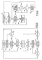
- FIG. 4 is a flowchart showing one preferred method of system operation for the embodiment of FIG. 3 .
- FIG. 5 is a flowchart of one preferred method for operating the pump control unit of FIG. 3 .
- FIG. 6 is a flowchart of one preferred method for operating the external unit of FIG. 3 .
- FIG. 7 is a timing diagram showing an example timing sequence according to FIGS. 4-6 .
- FIG. 8 is a block diagram of a second embodiment of the invention using two-way wireless communication.
- FIG. 9 is a flowchart showing one preferred method of system operation for the embodiment of FIG. 8 .
- FIG. 10 is a flowchart of one preferred method for operating the pump control unit of FIG. 8 .
- FIG. 11 is a flowchart of one preferred method for operating the external unit of FIG. 8 .
- FIG. 12 is a block diagram of a third embodiment of the invention using one-way wireless communication.
- FIG. 13 is a flowchart showing one preferred method of system operation for the embodiment of FIG. 12 .
- FIG. 14 is a flowchart of one preferred method for operating the pump control unit of FIG. 12 .
- FIG. 15 is a flowchart of one preferred method for operating the external unit of FIG. 12 .
- FIG. 16 is a timing diagram showing an example timing sequence according to FIGS. 13-15 .
- FIGS. 17 and 18 are block diagrams showing alternative embodiments for the backend communication to the centralized data management system.
- FIG. 19 is a block diagram showing an alternative embodiment using a smart phone device for the auxiliary unit.
- the external unit uses wired communication for secure aspects of heart pump operation such as pump configuration or parameter settings.
- a communication event includes a large amount of data, such as a controller software update
- the wired communication can provide a higher rate of data transfer than wireless.
- the external unit uses wireless communication for any other communications that don't require high security, such as data monitoring.
- the wireless communication allows patients to move freely and potentially to leave the hospital to go home while continuing to perform data monitoring.
- a preferred embodiment of the invention employs two different kinds of external units, a clinical external unit having a wired interface to the pump control unit and an auxiliary external unit having a wireless interface to the pump control unit.
- the clinical external unit may additionally have a wireless interface so that tethering by a cable is only necessary during the hospital stay when adjusting a secure pump operation.
- the software in a programmable device contained in the pump control unit can distinguish any commands it receives according to the interface over which it was received. If a pump operation command is received from the wireless interface, it is rejected because that is the wrong interface for such commands.
- the external unit does not need to be located at the patient's bedside. It can be placed at a nurse's station or in a doctor's room for easier access.
- the external unit can also provide the capability to prepare data for a central data management system located in the hospital from where the data of multiple patients can be managed together.
- the external unit can also be connected to a communication network such as the telephone system or the Internet to send data from a patient's home to the central data management system automatically.
- a communication network such as the telephone system or the Internet
- a blood pump 10 is implanted inside a human body 11 and connected to a pump control unit 12 worn by the patient. Power is supplied to pump control unit 12 from batteries 13 that are also worn by the patient. Pump control unit 12 may be connected to a clinical external unit 14 via a cable 15 . Wireless communication may also take place between pump control unit 12 and clinical external unit 14 .
- An auxiliary (e.g., home) external unit 16 has wireless communication with pump control unit 12 for data monitoring purposes.
- a centralized data management system 17 communicates with both clinical external unit 14 and auxiliary external unit 16 over any appropriate wired or wireless communication channel.
- step 20 When a command is received by the pump control unit, a check is made in step 20 to determine whether the received command corresponds to a secure operation of the pump. If it does, then a check is made at step 21 to determine whether the command was received over the wired interface. If not, then the command is ignored at step 22 and the wireless interface is, therefore, unable to consummate a pump operating command. If it is determined at step 21 that the command was received at the wired interface, then the command is processed at step 23 . If the command received at step 20 is not a secure operation, then a check is made at step 24 to determine whether the received command corresponds to a download of information (e.g., updating of software).
- a download of information e.g., updating of software
- commands that may be sent wirelessly from an external unit to the pump control unit include requests for performance-related data and acknowledgements of previously received communications.
- Pump control unit 12 includes a programmable device such as a microcontroller 25 having a memory 26 and connected to pump 10 by an input/output interface 27 .
- a hardwired interface between microcontroller 25 and clinical unit 14 includes a UART 28 coupled between microcontroller 25 and a cable connector 29 .
- Microcontroller 25 further has a wireless interface comprised of a UART 30 connected to a wireless transceiver 31 .
- Transceiver 31 may utilize a known wireless protocol such as Bluetooth, for example.
- Compatible transceivers 32 and 33 are contained in clinical external unit 14 and auxiliary external unit 16 .
- Units 14 and 16 are further connected to a centralized data management system 17 for optional collection and long term archival of data.
- the microcontroller preferably operates the wireless interface in two respective modes, a polling mode and a data transfer mode.
- the controller sends a polling command over the wireless interface in step 35 .
- the external unit receives a polling command then it generates an acknowledgement or handshake response and sends it wirelessly back to the pump control unit.
- a check is made in step 36 to determine whether the microcontroller received a response from the external unit. If not, then the microcontroller remains in the polling mode and returns to the transmission of a polling command in step 35 . If a response from the external unit is received, then the microcontroller enters the data transfer mode and sends data wirelessly in step 37 .
- step 38 As the microcontroller sends data, a check is made in step 38 to determine whether a handshake is maintained with the external unit in step 38 . If handshake is lost while data is being sent, then a return in made to step 35 . If handshake is maintained, then a check is made in step 39 to determine whether the microcontroller has any remaining data to be sent. If so, then a return is made to step 37 . Otherwise, the external unit merely waits for the next external command to be received from the controller in step 40 .
- the polling command is sent in step 41 .
- the microcontroller waits for a response from the external unit in step 42 .
- a check is made in step 43 to determine whether a response was received from the external unit. If not, then a check is made in step 44 to determine whether the expected time for receiving a response has timed out. If not, then a return is made to step 42 to wait for a response. If timed out, then a return is made to step 41 to repeat the polling command.
- a check is made in step 45 to determine whether any additional data is present in the pump control unit that should be sent to the external unit.
- step 41 If not, then a return is made to step 41 to send a polling command whenever additional data becomes available. Otherwise, a packet of data is sent to the external unit in step 46 . A check is made in step 47 to determine whether all data packets have been sent. If not, then a return is made to step 46 for sending the additional data packet. Once all data is sent, the microcontroller waits for a response from the external unit in step 48 . A check is made in step 49 to determine whether a response has been received from the external unit. If so, then a check is made in step 50 to determine whether correct reception of the data is acknowledged by the external unit. If not, then a return is made to step 46 to resend the data.
- step 41 If the response from the external unit acknowledges error-free reception, then a return is made to step 41 to re-initiate polling when another data transfer becomes necessary. If no response has been received from the external unit in step 49 , then a check is made for a timed-out condition in step 51 . If not timed out, then a return is made to step 48 to continue waiting for a response. If timed out, then return is made to step 41 to reinitiate the data transfer.
- FIG. 6 shows the operation at the external unit in greater detail.
- the external unit waits for a command from the controller at step 55 . Once a command is received, a check is performed in step 56 to determine whether a first data packet has been received from the controller. If not, then a return is made to step 55 . Otherwise, a check is made in step 57 to determine whether all packets for a particular data transfer command had been received. If yes, then the external unit sends an acknowledgement response to the controller in step 58 and then returns to step 55 to wait for the next command. If all packets are not received in step 57 , then the external unit waits for the next packet from the controller in step 60 . It checks in step 61 to determine whether the next packet has been received.
- step 57 determines whether all packets have now been received. If not, then a check is made in step 62 to determine whether the expected delay has timed out. If not, then a return is made to step 60 to wait for the next packet. Otherwise, a timeout is detected and the external unit sends a response indicative of failure to the controller and then returns to step 55 for waiting for the next command.
- FIG. 7 shows a timing diagram wherein various actions are given in a timing sequence moving from the top of FIG. 7 toward the bottom.
- the controller sends a polling command at an event 65 . It then starts its timeout timer at an event 66 .
- the polling command at event 65 is not received by the external unit (e.g., it is out of range) so that there is no response.
- the timeout timer expires at an event 67 causing the controller to initiate a new polling command at an event 68 .
- the controller restarts the timeout timer at event 69 , but this time a response is received from the external unit at an event 70 causing the controller to stop the timer at an event 71 .
- the controller Based on the response, the controller sends a packet of data to the external unit at an event 72 .
- the timeout timer is again started at an event 73 while the controller continues to send packets of the data.
- a last packet is sent at an event 74 followed by an acknowledgement response from the external unit at event 75 causing the controller to stop the timeout timer at event 76 .
- the controller When the controller again has data to be automatically sent to the external unit, it begins a new polling command at event 77 .
- the polling timeout timer is started at event 78 , and a response is received at event 79 .
- the controller stops the timer at event 80 and then begins to send data at event 81 . It starts the sending timeout timer at event 82 , but the wireless link again fails between the controller and the external unit (e.g., they are moved out of range) resulting in a time out condition at an event 83 . Thereafter, the controller periodically generates polling commands in an attempt to reestablish communication with the external unit.
- FIG. 8 An alternative embodiment employing two-way wireless communication between pump control unit 12 and external units 14 and/or 16 is shown in FIG. 8 .
- the polling mode employs two-way wireless communication while only one-way wireless communication is enabled during the data transfer mode. In other words, reception of a wireless acknowledgement signal from the external unit to the pump control unit is not allowed. Instead, user intervention provides the acknowledgement by virtue of an alert LED 85 on the clinical external unit 14 and an alert LED 86 on the auxiliary unit 16 .
- the alert LEDs operate in conjunction with a reset button 87 that is provided on the pump control unit 12 in communication with microcontroller 25 .
- Reset button 87 is a switch element that can be manually activated to initiate an input signal to microcontroller 25 .
- Alert LEDs 85 and 86 can alternatively take the form of any visual indicator such as any optical display or light, or any audible indicator such as a beep from a speaker.
- Auxiliary unit 16 as shown in FIG. 8 may preferably be a home data unit taken with the patient while away from the hospital.
- auxiliary unit 16 includes a modem 88 (which may be a dial up modem or a cable modem, for example) to communicate with internet 89 for transferring data to system 17 .
- FIG. 9 A preferred communication protocol for the system of FIG. 8 is shown in FIG. 9 including a bi-directional communication portion 90 and a single-directional communication portion 91 .
- the pump controller begins in a bi-directional communication state and sends a polling command in step 92 .
- a check is made in step 93 to determine whether the controller receives a wireless acknowledgement response from the external unit. Once a response is received, the controller disables its receiving functionality in step 94 and enters a single-directional communication state.
- the controller sends a data command reporting the performance-related data in step 95 .
- the external unit checks to determine whether a predetermined period of time has timed out without receiving a command from the controller since the external unit responded to the polling command. If not, then the external unit checks in step 97 to determine whether it received a last data packet. If not, then it waits for the next packet in step 98 . After receiving the last packet, the external unit waits for the next command from the controller in step 99 .
- step 96 If the external unit times out at step 96 , then it generates an alert indication in step 100 (e.g., by turning on an alert LED or by generating an audible beep) to prompt the user to press the reset button.
- FIG. 10 shows a preferred operating method of the pump control unit for the embodiment of FIGS. 8 and 9 .
- the controller sends the polling command in step 105 and waits for a response from the external unit in step 106 .
- a check is made in step 107 to determine whether a response is received from the external unit. If not, then another polling command is sent in step 105 . If the acknowledgement was received, then the receiving function of the pump control unit is disabled in step 108 .
- the controller checks in step 109 to determine whether there is any required data to be sent to the external unit. If not, then it waits until the data is ready in step 110 . When data is ready, then the controller sends a packet of the data to the external unit in step 111 .
- step 112 It checks in step 112 to determine whether all data has been sent and continues sending in step 111 until all data is sent. A check is made in step 113 to determine whether the reset button has been pressed. If not, then the controller continues sending data as it becomes available at step 109 . When the reset button is pressed, the controller enables receiving at step 114 and returns to step 105 to send a polling command.
- FIG. 11 shows a preferred operating method of the external unit according to the embodiment of FIGS. 8 and 9 .
- the external unit waits for a polling command in step 115 .
- Step 116 determines whether a polling command has been received. Once a polling command is detected, the external unit sends a response to the controller in step 117 .
- the external unit waits for a data command in step 118 and checks in step 119 to determine whether a first packet for the command has been received. After receiving the first packet, the external unit waits for the next packet in step 120 . If a next packet is not detected in step 121 , then a check is made in step 122 to determine if a predetermined time period has timed out.
- step 120 the external unit continues to wait for the next packet in step 120 . If timed out in step 122 , then the external unit activates the indicator to indicate that handshake has been lost with the pump control unit so that the user will be prompted to reset the communication by pressing the reset button. Then the external unit waits for a polling command in step 115 . If a next packet is received in step 121 , then a check is made in step 124 to is determine whether all packets for the command have been received. If not, then the external unit returns to step 120 to wait for the next packet. Once all packets are received, then a return is made to step 118 to wait for the next command.
- FIG. 12 shows an embodiment of the invention employing only one-way wireless communication from pump control unit 12 to external units 14 and/or 16 .
- pump control unit 12 includes a transmitter 125 instead of a transceiver and external units 14 and 16 have receivers 126 and 127 , respectively.
- alert indicators 85 and 86 external units 14 and 16 include acknowledgement indicators 128 and 129 .
- pump control unit 12 includes a start button 130 connected to microcontroller 25 . In this embodiment, no wireless commands can be sent from the external units to the pump control unit. Therefore, the pump control unit cannot obtain an automatic wireless response to its polling command. Instead, manual intervention (e.g., by the patient) is utilized as follows.
- FIG. 13 shows the overall communication protocol for FIG. 12 .
- the controller sends a polling command on a periodic basis (e.g., once per minute).
- the external unit continuously checks to determine whether it has received a polling command from the controller. If not, then it waits for such a command in step 133 .
- a polling command is received by the external unit, it indicates this in step 134 by generating an acknowledgement indication (turning on the LED, generating a message on a display, creating an audible sound, or any other perceivable signal).
- the user presses the start button on the pump control unit in step 135 .
- the microcontroller detects the signal from the start button and then initiates wireless transmission of a data command in step 136 .
- the external unit checks for a timed out condition in step 137 . If the external unit has timed out for receiving a command, then it shows in alert indication in step 138 . When the user sees the alert signal, the user presses the reset button in step 139 causing the controller to return to its polling command in step 131 .
- the external unit determines in step 140 whether it has received the last packet for the command. If not, then it waits for the last packet in step 141 . When the last command is received, the external unit waits for the next command from the controller in step 142 .
- Operation of the pump control unit is shown in greater detail in FIG. 14 . It sends a polling command in step 145 and then waits a predetermined time in step 146 until it checks in step 147 to determine whether the start button was pressed. Once it determines that the start button was pressed, the pump control unit sends any required data in step 148 . It continues to send data in steps 150 and 151 until all data has been sent. The pump control unit checks whether the reset button was pressed in step 152 . If not, then data continues to be sent. However, once the reset button is pressed in step 152 , then the pump control unit immediately returns to step 145 to send a polling command.
- FIG. 15 shows the operation of the external unit in greater detail. It waits for reception of a polling command in steps 155 and 156 .
- the external unit turns on the acknowledgement indicator to show that a handshake should be initiated with the pump control unit by means of the user pressing the start button.
- the external unit waits for a command from the controller in step 158 and checks for reception of a first data packet in step 159 . After receiving a first packet, the external unit waits for next data packets in step 160 while detecting reception or timing out of the next packets in step 161 and 162 .
- Step 164 determines whether all packets are received and then returns to step 158 for a next command.
- FIG. 16 is a timing diagram corresponding to the embodiment of FIGS. 12-15 .
- the controller sends a polling command at an event 165 and starts the timer at event 166 .
- the external unit does not receive the initial polling command and so the time-out timer reaches a timed-out condition at event 167 .
- the controller sends a new polling command at event 168 which is received by the external unit, thereby causing is the external unit to show an acknowledgement indication at an event 169 .
- the indication is seen by the user who presses the start button at an event 170 .
- the controller begins sending data packets at an event 171 . As the external unit waits for data packets from the controller, it starts and stops its own time out timer at events 172 - 174 .
- the time-out timer in the external unit has expired without receiving a last packet of data.
- the external unit shows an alert indication at an event 176 to show that there was an incomplete transmission.
- the user sees the alert indication and presses the reset button at an event 177 .
- the controller reinitiates a sequence involving the reception of the polling command by the external unit, pressing of the start button by the user, and resumption of transmission of data packets.
- a telephone line 180 is shown for interconnecting auxiliary unit 16 and centralized data management system 17 .
- an Internet connection 181 can be used as shown in FIG. 17 .
- a cellular network connection 182 can be employed as shown in FIG. 18 as part of a data link between auxiliary unit 16 and data management system 17 .
- the auxiliary unit periodically establishes a communication link to the data management system in order to provide updated data that has been collected from the pump control unit.
- FIG. 19 shows another embodiment employing a smart phone 183 for implementing the auxiliary unit together with the communication link to data management system 17 .
- an appropriate software application is provided for smart phone 183 allowing it to communicate wirelessly with pump control unit 12 to obtain patient and performance-related data and to periodically transmit the data to the data management system.
Abstract
Description
Claims (9)
Priority Applications (1)
| Application Number | Priority Date | Filing Date | Title |
|---|---|---|---|
| US11/999,858 US7794384B2 (en) | 2007-12-07 | 2007-12-07 | Dual communication interface for artificial heart system |
Applications Claiming Priority (1)
| Application Number | Priority Date | Filing Date | Title |
|---|---|---|---|
| US11/999,858 US7794384B2 (en) | 2007-12-07 | 2007-12-07 | Dual communication interface for artificial heart system |
Publications (2)
| Publication Number | Publication Date |
|---|---|
| US20090149951A1 US20090149951A1 (en) | 2009-06-11 |
| US7794384B2 true US7794384B2 (en) | 2010-09-14 |
Family
ID=40722436
Family Applications (1)
| Application Number | Title | Priority Date | Filing Date |
|---|---|---|---|
| US11/999,858 Expired - Fee Related US7794384B2 (en) | 2007-12-07 | 2007-12-07 | Dual communication interface for artificial heart system |
Country Status (1)
| Country | Link |
|---|---|
| US (1) | US7794384B2 (en) |
Cited By (10)
| Publication number | Priority date | Publication date | Assignee | Title |
|---|---|---|---|---|
| US20090054782A1 (en) * | 2007-08-24 | 2009-02-26 | Shinichi Amemiya | Ultrasound diagnostic apparatus |
| WO2015048920A1 (en) * | 2013-10-03 | 2015-04-09 | 北京精密机电控制设备研究所 | Blood pump control system and blood pump system |
| US20150109125A1 (en) * | 2010-11-08 | 2015-04-23 | Zoll Medical Corporation | Remote medical device alarm |
| US10328275B2 (en) | 2007-06-07 | 2019-06-25 | Zoll Medical Corporation | Medical device configured to test for user responsiveness |
| US10413649B2 (en) | 2014-10-01 | 2019-09-17 | Heartware, Inc. | Back up controller system with updating |
| US11368081B2 (en) | 2018-01-24 | 2022-06-21 | Kardion Gmbh | Magnetic coupling element with a magnetic bearing function |
| US11568984B2 (en) | 2018-09-28 | 2023-01-31 | Zoll Medical Corporation | Systems and methods for device inventory management and tracking |
| US11699551B2 (en) | 2020-11-05 | 2023-07-11 | Kardion Gmbh | Device for inductive energy transmission in a human body and use of the device |
| US11752354B2 (en) | 2018-05-02 | 2023-09-12 | Kardion Gmbh | Transmitter unit comprising a transmission coil and a temperature sensor |
| US11881721B2 (en) | 2018-05-02 | 2024-01-23 | Kardion Gmbh | Wireless energy transfer system with fault detection |
Families Citing this family (5)
| Publication number | Priority date | Publication date | Assignee | Title |
|---|---|---|---|---|
| EP3906963A1 (en) * | 2008-10-10 | 2021-11-10 | Medical Tree Patent Ltd | Heart help pump |
| AU2011222506B8 (en) * | 2010-03-05 | 2014-04-24 | Minnetronix Inc. | Portable controller with integral power source for mechanical circulation support systems |
| US8556795B2 (en) | 2010-11-23 | 2013-10-15 | Minnetronix Inc. | Portable controller with integral power source for mechanical circulation support systems |
| US10130743B2 (en) | 2015-11-17 | 2018-11-20 | Dale J. Yeatts | Wireless diagnostic system for indirect flow measurement in artificial heart pumps |
| US20210290934A1 (en) * | 2018-07-17 | 2021-09-23 | Viaderm Llc | Indwelling hyper-dimensional cardiac physiologic data logging and transmission system and method of doing business |
Citations (18)
| Publication number | Priority date | Publication date | Assignee | Title |
|---|---|---|---|---|
| US5309920A (en) * | 1991-11-12 | 1994-05-10 | Stuart Medical Inc. | Ambulatory electrocardiographic patient monitoring system and method therefor |
| US5342408A (en) * | 1993-01-07 | 1994-08-30 | Incontrol, Inc. | Telemetry system for an implantable cardiac device |
| US6106551A (en) | 1996-02-29 | 2000-08-22 | Minnesota Mining & Manufacturing | Communication method for implantable medical device |
| US6123726A (en) | 1997-07-25 | 2000-09-26 | Seiko Epson Corporation | Portable drive system for artificial heart |
| US6183412B1 (en) | 1997-10-02 | 2001-02-06 | Micromed Technology, Inc. | Implantable pump system |
| US6336900B1 (en) * | 1999-04-12 | 2002-01-08 | Agilent Technologies, Inc. | Home hub for reporting patient health parameters |
| US6409674B1 (en) | 1998-09-24 | 2002-06-25 | Data Sciences International, Inc. | Implantable sensor with wireless communication |
| US20020143372A1 (en) * | 2001-03-29 | 2002-10-03 | Snell Jeffery D. | System and method for remote programming of implantable cardiac stimulation devices |
| US6511412B1 (en) | 1998-09-30 | 2003-01-28 | L. Vad Technology, Inc. | Cardivascular support control system |
| US20040204743A1 (en) * | 2003-01-14 | 2004-10-14 | Mcgrath Thomas J. | Remotely operating external medical devices |
| US20040260363A1 (en) * | 2003-06-23 | 2004-12-23 | Arx Jeffrey A. Von | Secure long-range telemetry for implantable medical device |
| US20050014991A1 (en) | 2003-06-12 | 2005-01-20 | Terumo Kabushiki Kaisha | Artificial heart pump system and its control apparatus |
| US6925328B2 (en) | 2000-04-20 | 2005-08-02 | Biophan Technologies, Inc. | MRI-compatible implantable device |
| US20060017575A1 (en) * | 2004-07-20 | 2006-01-26 | Medtronic, Inc. | Alert system and method for an implantable medical device |
| US20060149339A1 (en) * | 2002-10-31 | 2006-07-06 | Medtronic, Inc. | Aggregation of data from external data sources within an implantable medical device |
| US20070123946A1 (en) * | 2005-11-30 | 2007-05-31 | Javaid Masoud | Protocol implementation for telemetry communications involving implantable medical devices |
| US20070197854A1 (en) * | 2006-01-27 | 2007-08-23 | Circulite, Inc. | Heart assist system |
| US20070254593A1 (en) * | 2006-04-28 | 2007-11-01 | Medtronic Minimed, Inc. | Wireless data communication for a medical device network that supports a plurality of data communication modes |
-
2007
- 2007-12-07 US US11/999,858 patent/US7794384B2/en not_active Expired - Fee Related
Patent Citations (18)
| Publication number | Priority date | Publication date | Assignee | Title |
|---|---|---|---|---|
| US5309920A (en) * | 1991-11-12 | 1994-05-10 | Stuart Medical Inc. | Ambulatory electrocardiographic patient monitoring system and method therefor |
| US5342408A (en) * | 1993-01-07 | 1994-08-30 | Incontrol, Inc. | Telemetry system for an implantable cardiac device |
| US6106551A (en) | 1996-02-29 | 2000-08-22 | Minnesota Mining & Manufacturing | Communication method for implantable medical device |
| US6123726A (en) | 1997-07-25 | 2000-09-26 | Seiko Epson Corporation | Portable drive system for artificial heart |
| US6183412B1 (en) | 1997-10-02 | 2001-02-06 | Micromed Technology, Inc. | Implantable pump system |
| US6409674B1 (en) | 1998-09-24 | 2002-06-25 | Data Sciences International, Inc. | Implantable sensor with wireless communication |
| US6511412B1 (en) | 1998-09-30 | 2003-01-28 | L. Vad Technology, Inc. | Cardivascular support control system |
| US6336900B1 (en) * | 1999-04-12 | 2002-01-08 | Agilent Technologies, Inc. | Home hub for reporting patient health parameters |
| US6925328B2 (en) | 2000-04-20 | 2005-08-02 | Biophan Technologies, Inc. | MRI-compatible implantable device |
| US20020143372A1 (en) * | 2001-03-29 | 2002-10-03 | Snell Jeffery D. | System and method for remote programming of implantable cardiac stimulation devices |
| US20060149339A1 (en) * | 2002-10-31 | 2006-07-06 | Medtronic, Inc. | Aggregation of data from external data sources within an implantable medical device |
| US20040204743A1 (en) * | 2003-01-14 | 2004-10-14 | Mcgrath Thomas J. | Remotely operating external medical devices |
| US20050014991A1 (en) | 2003-06-12 | 2005-01-20 | Terumo Kabushiki Kaisha | Artificial heart pump system and its control apparatus |
| US20040260363A1 (en) * | 2003-06-23 | 2004-12-23 | Arx Jeffrey A. Von | Secure long-range telemetry for implantable medical device |
| US20060017575A1 (en) * | 2004-07-20 | 2006-01-26 | Medtronic, Inc. | Alert system and method for an implantable medical device |
| US20070123946A1 (en) * | 2005-11-30 | 2007-05-31 | Javaid Masoud | Protocol implementation for telemetry communications involving implantable medical devices |
| US20070197854A1 (en) * | 2006-01-27 | 2007-08-23 | Circulite, Inc. | Heart assist system |
| US20070254593A1 (en) * | 2006-04-28 | 2007-11-01 | Medtronic Minimed, Inc. | Wireless data communication for a medical device network that supports a plurality of data communication modes |
Cited By (26)
| Publication number | Priority date | Publication date | Assignee | Title |
|---|---|---|---|---|
| US11207539B2 (en) | 2007-06-07 | 2021-12-28 | Zoll Medical Corporation | Medical device configured to test for user responsiveness |
| US10434321B2 (en) | 2007-06-07 | 2019-10-08 | Zoll Medical Corporation | Medical device configured to test for user responsiveness |
| US10328275B2 (en) | 2007-06-07 | 2019-06-25 | Zoll Medical Corporation | Medical device configured to test for user responsiveness |
| US20090054782A1 (en) * | 2007-08-24 | 2009-02-26 | Shinichi Amemiya | Ultrasound diagnostic apparatus |
| US9925387B2 (en) * | 2010-11-08 | 2018-03-27 | Zoll Medical Corporation | Remote medical device alarm |
| US10881871B2 (en) | 2010-11-08 | 2021-01-05 | Zoll Medical Corporation | Remote medical device alarm |
| US11951323B2 (en) | 2010-11-08 | 2024-04-09 | Zoll Medical Corporation | Remote medical device alarm |
| US9937355B2 (en) | 2010-11-08 | 2018-04-10 | Zoll Medical Corporation | Remote medical device alarm |
| US10159849B2 (en) | 2010-11-08 | 2018-12-25 | Zoll Medical Corporation | Remote medical device alarm |
| US11198017B2 (en) | 2010-11-08 | 2021-12-14 | Zoll Medical Corporation | Remote medical device alarm |
| US11691022B2 (en) | 2010-11-08 | 2023-07-04 | Zoll Medical Corporation | Remote medical device alarm |
| US10485982B2 (en) | 2010-11-08 | 2019-11-26 | Zoll Medical Corporation | Remote medical device alarm |
| US20150109125A1 (en) * | 2010-11-08 | 2015-04-23 | Zoll Medical Corporation | Remote medical device alarm |
| US10434233B2 (en) * | 2013-10-03 | 2019-10-08 | Beijing Research Institute Of Precise Mechatronics And Controls | Blood pump control system and blood pump system |
| EP3053613A4 (en) * | 2013-10-03 | 2017-08-09 | Beijing Research Institute of Precise Mechatronics and Controls | Blood pump control system and blood pump system |
| US20160263299A1 (en) * | 2013-10-03 | 2016-09-15 | Beijing Research Institute Of Precise Mechatronics Controls | Blood pump control system and blood pump system |
| WO2015048920A1 (en) * | 2013-10-03 | 2015-04-09 | 北京精密机电控制设备研究所 | Blood pump control system and blood pump system |
| RU2618909C2 (en) * | 2013-10-03 | 2017-05-11 | Бейджинг Рисёрч Инститьют Оф Присайз Мекатроникс Энд Контроулз | Management system for blood discharge pump and blood discharge pump system |
| US10413649B2 (en) | 2014-10-01 | 2019-09-17 | Heartware, Inc. | Back up controller system with updating |
| US11804767B2 (en) | 2018-01-24 | 2023-10-31 | Kardion Gmbh | Magnetic coupling element with a magnetic bearing function |
| US11368081B2 (en) | 2018-01-24 | 2022-06-21 | Kardion Gmbh | Magnetic coupling element with a magnetic bearing function |
| US11752354B2 (en) | 2018-05-02 | 2023-09-12 | Kardion Gmbh | Transmitter unit comprising a transmission coil and a temperature sensor |
| US11881721B2 (en) | 2018-05-02 | 2024-01-23 | Kardion Gmbh | Wireless energy transfer system with fault detection |
| US11568984B2 (en) | 2018-09-28 | 2023-01-31 | Zoll Medical Corporation | Systems and methods for device inventory management and tracking |
| US11894132B2 (en) | 2018-09-28 | 2024-02-06 | Zoll Medical Corporation | Systems and methods for device inventory management and tracking |
| US11699551B2 (en) | 2020-11-05 | 2023-07-11 | Kardion Gmbh | Device for inductive energy transmission in a human body and use of the device |
Also Published As
| Publication number | Publication date |
|---|---|
| US20090149951A1 (en) | 2009-06-11 |
Similar Documents
| Publication | Publication Date | Title |
|---|---|---|
| US7794384B2 (en) | Dual communication interface for artificial heart system | |
| JP5069472B2 (en) | Wireless medical monitoring method and related system and patient monitoring apparatus | |
| US10806841B2 (en) | System of medical treatment units and peripheral devices | |
| EP2769298B1 (en) | Secure automatic configuration of equipment through replication | |
| EP1631929B1 (en) | A portable patient monitoring system including location identification capability | |
| CN109644327B (en) | Method for wireless data communication between a sensor system and a receiver and system for wireless data communication | |
| JP6118028B2 (en) | Wireless monitoring system and method with dual mode alarm | |
| US20050080322A1 (en) | Monitoring method and monitoring system for assessing physiological parameters of a subject | |
| US9878081B2 (en) | Arrangement comprising medical treatment units and peripheral devices as well as a peripheral device and treatment unit for use in such an arrangement | |
| AU2005202514A1 (en) | Methods of monitoring the concentration of an analyte | |
| AU2005202519A1 (en) | Analyte monitoring system with wireless alarm | |
| EP2805564A1 (en) | Wireless relay module for remote monitoring systems having power and medical device proximmmmity monitoring functionality | |
| US10922961B2 (en) | Remote communication with multiple dialysis machines | |
| KR20150116206A (en) | Method of providing emergency notification using wearable bluetooth biometrie devices, and computer-readable recording medium for the same | |
| CN103544825B (en) | Data based on central monitoring system select transmission method and system | |
| KR100916483B1 (en) | APPARATUS AND METHOD FOR MONITORING patient | |
| JP2015500669A (en) | Peritoneal dialysis machine | |
| JP2015532159A (en) | Device for controlling a surgical handpiece | |
| US20140257849A1 (en) | Patient support apparatus configured for communicating with implantable devices | |
| CN108992724A (en) | Dialysis procedure automatic monitoring warning method and its system | |
| CN209771019U (en) | Infusion alarm system and infusion bag | |
| CN213667227U (en) | Infusion set based on zigbee | |
| JP2020505859A (en) | Sensor data quality as a trigger for confirmation of physical presence and facilitation of unpairing | |
| JPH09299479A (en) | Drip monitoring apparatus | |
| JP2001120506A (en) | Health care terminal |
Legal Events
| Date | Code | Title | Description |
|---|---|---|---|
| AS | Assignment |
Owner name: TERUMO HEART INCORPORATED, MICHIGAN Free format text: ASSIGNMENT OF ASSIGNORS INTEREST;ASSIGNORS:SUGIURA, NAOYA;MEDVEDEV, ALEXANDER;REEL/FRAME:020271/0744 Effective date: 20071205 |
|
| AS | Assignment |
Owner name: TERUMO KABUSHIKI KAISHA, JAPAN Free format text: ASSIGNMENT OF ASSIGNORS INTEREST;ASSIGNOR:TERUMO HEART, INCORPORATED;REEL/FRAME:023399/0754 Effective date: 20091013 |
|
| STCF | Information on status: patent grant |
Free format text: PATENTED CASE |
|
| AS | Assignment |
Owner name: THORATEC CORPORATION, CALIFORNIA Free format text: ASSIGNMENT OF ASSIGNORS INTEREST;ASSIGNOR:TERUMO KABUSHIKI KAISHA;REEL/FRAME:031016/0364 Effective date: 20130630 |
|
| FPAY | Fee payment |
Year of fee payment: 4 |
|
| AS | Assignment |
Owner name: THORATEC LLC, CALIFORNIA Free format text: CHANGE OF NAME;ASSIGNOR:THORATEC CORPORATION;REEL/FRAME:041428/0327 Effective date: 20151112 Owner name: TC1 LLC, CALIFORNIA Free format text: ASSIGNMENT OF ASSIGNORS INTEREST;ASSIGNOR:THORATEC LLC;REEL/FRAME:041428/0685 Effective date: 20161114 |
|
| MAFP | Maintenance fee payment |
Free format text: PAYMENT OF MAINTENANCE FEE, 8TH YEAR, LARGE ENTITY (ORIGINAL EVENT CODE: M1552) Year of fee payment: 8 |
|
| FEPP | Fee payment procedure |
Free format text: MAINTENANCE FEE REMINDER MAILED (ORIGINAL EVENT CODE: REM.); ENTITY STATUS OF PATENT OWNER: LARGE ENTITY |
|
| LAPS | Lapse for failure to pay maintenance fees |
Free format text: PATENT EXPIRED FOR FAILURE TO PAY MAINTENANCE FEES (ORIGINAL EVENT CODE: EXP.); ENTITY STATUS OF PATENT OWNER: LARGE ENTITY |
|
| STCH | Information on status: patent discontinuation |
Free format text: PATENT EXPIRED DUE TO NONPAYMENT OF MAINTENANCE FEES UNDER 37 CFR 1.362 |
|
| FP | Lapsed due to failure to pay maintenance fee |
Effective date: 20220914 |