US7796389B2 - Method and apparatus for cooling electronics - Google Patents
Method and apparatus for cooling electronics Download PDFInfo
- Publication number
- US7796389B2 US7796389B2 US12/324,757 US32475708A US7796389B2 US 7796389 B2 US7796389 B2 US 7796389B2 US 32475708 A US32475708 A US 32475708A US 7796389 B2 US7796389 B2 US 7796389B2
- Authority
- US
- United States
- Prior art keywords
- fluid
- heat sink
- heat
- fluid path
- vapor chamber
- Prior art date
- Legal status (The legal status is an assumption and is not a legal conclusion. Google has not performed a legal analysis and makes no representation as to the accuracy of the status listed.)
- Expired - Fee Related, expires
Links
Images


Classifications
-
- H—ELECTRICITY
- H01—ELECTRIC ELEMENTS
- H01L—SEMICONDUCTOR DEVICES NOT COVERED BY CLASS H10
- H01L23/00—Details of semiconductor or other solid state devices
- H01L23/34—Arrangements for cooling, heating, ventilating or temperature compensation ; Temperature sensing arrangements
- H01L23/42—Fillings or auxiliary members in containers or encapsulations selected or arranged to facilitate heating or cooling
- H01L23/427—Cooling by change of state, e.g. use of heat pipes
-
- F—MECHANICAL ENGINEERING; LIGHTING; HEATING; WEAPONS; BLASTING
- F28—HEAT EXCHANGE IN GENERAL
- F28D—HEAT-EXCHANGE APPARATUS, NOT PROVIDED FOR IN ANOTHER SUBCLASS, IN WHICH THE HEAT-EXCHANGE MEDIA DO NOT COME INTO DIRECT CONTACT
- F28D15/00—Heat-exchange apparatus with the intermediate heat-transfer medium in closed tubes passing into or through the conduit walls ; Heat-exchange apparatus employing intermediate heat-transfer medium or bodies
- F28D15/02—Heat-exchange apparatus with the intermediate heat-transfer medium in closed tubes passing into or through the conduit walls ; Heat-exchange apparatus employing intermediate heat-transfer medium or bodies in which the medium condenses and evaporates, e.g. heat pipes
- F28D15/0233—Heat-exchange apparatus with the intermediate heat-transfer medium in closed tubes passing into or through the conduit walls ; Heat-exchange apparatus employing intermediate heat-transfer medium or bodies in which the medium condenses and evaporates, e.g. heat pipes the conduits having a particular shape, e.g. non-circular cross-section, annular
-
- H—ELECTRICITY
- H01—ELECTRIC ELEMENTS
- H01L—SEMICONDUCTOR DEVICES NOT COVERED BY CLASS H10
- H01L23/00—Details of semiconductor or other solid state devices
- H01L23/34—Arrangements for cooling, heating, ventilating or temperature compensation ; Temperature sensing arrangements
- H01L23/46—Arrangements for cooling, heating, ventilating or temperature compensation ; Temperature sensing arrangements involving the transfer of heat by flowing fluids
- H01L23/473—Arrangements for cooling, heating, ventilating or temperature compensation ; Temperature sensing arrangements involving the transfer of heat by flowing fluids by flowing liquids
-
- H—ELECTRICITY
- H01—ELECTRIC ELEMENTS
- H01L—SEMICONDUCTOR DEVICES NOT COVERED BY CLASS H10
- H01L2924/00—Indexing scheme for arrangements or methods for connecting or disconnecting semiconductor or solid-state bodies as covered by H01L24/00
- H01L2924/0001—Technical content checked by a classifier
- H01L2924/0002—Not covered by any one of groups H01L24/00, H01L24/00 and H01L2224/00
Definitions
- the subject matter disclosed herein relates to improved heat dissipation techniques, e.g., a heatsink for electronic devices.
- Heatsinks are used to increase heat dissipation in many types of electronic equipment, such as power converters, motor drives, processors, power transmission devices, and batteries. Improved methods and devices for dissipating the heat generated by high power-density electronics may increase the power handling capabilities of these devices.
- Embodiments of the present disclosure provide for methods and devices for improving the heat dissipating properties of a heatsink to provide increased cooling for electronic equipment, such as power converters.
- a heatsink includes at least one fluid cooled portion and at least one heat pipe disposed adjacent to the fluid cooled portion. The heat pipe improves the conduction of heat away from heat sources.
- FIG. 1 is a cross-sectional view of an improved heatsink, in accordance with certain embodiments
- FIG. 2 is a partial, cross-sectional view of the heatsink of FIG. 1 , taken within line 2 - 2 , in accordance with certain embodiments;
- FIG. 3 is a perspective, cut-away view of the improved heatsink of FIG. 1 , taken along line 3 - 3 , in accordance with certain embodiments;
- FIGS. 4 and 5 are cross-sectional views of embodiments of heatsinks
- FIG. 6 is a block diagram of an exemplary power converter system that employs an improved heatsink, in accordance with certain embodiments
- FIGS. 7-9 are cross-sectional, top views of various heat spreaders that may be used with the improved heatsink, in accordance with certain embodiments.
- FIGS. 10-13 depict alternative embodiments of heatsinks.
- Embodiments of the disclosed heat sink include a fluid cooled plate in combination with a heat spreading device that spreads heat laterally across the fluid cooled plate. Spreading heat laterally improves the ability of the heatsink to conduct heat away from heat generating devices, and increases the surface area of heat dissipation.
- the disclosed heatsink includes an internal heat exchanger (e.g., fins and channels) and a vapor chamber and/or heat pipes.
- the heat exchanger may include rows of fins (e.g., a folded fin configuration) to facilitate heat transfer to a fluid (e.g., liquid or gas) flowing through an interior of the heatsink from an inlet to an outlet.
- the disclosed heatsink may be a single structure or multiple pieces coupled together to define a closed body about the heat exchanger and vapor chamber and/or heat pipes.
- the heatsink may include external fins to enable convective heat transfer with or without an external fan.
- the disclosed heatsink also may include multiple layers of heat exchangers, vapor chambers, heat pipes, and other cooling features (e.g., an alternating arrangement).
- the improved heatsink provides increased cooling for use in a variety of high power-density applications.
- embodiments of the disclosed heatsink may be used with a power converter.
- the disclosed heatsink may be mounted to a single component or multiple components (e.g., chips, memory, processors, etc.).
- FIG. 1 is a cross-sectional view of an improved heatsink 10 in accordance with an embodiment.
- FIG. 1 shows the heatsink 10 disposed adjacent to one or more heat generating circuits 12 on a circuit board 14 .
- the circuits 12 may be any type of heat generating circuits such as a processors, memory devices, amplifiers, switches, etc. As will be explained further below in relation to FIG. 6 , the circuits 12 may be high-power, solid-state switches such as those used in an inverter module.
- the circuits 12 may interface the heatsink 10 with a layer of thermally conductive material, such as thermal grease.
- the heatsink 10 may couple to the circuit board 14 and/or the heat generating circuits 12 .
- the heatsink 10 may couple to the circuit board 14 via screws, bolts, nap-fit clamps, spring-loaded clamps, or other suitable releasable or fixed couplings.
- the circuits 12 may be soldered to the heatsink 10 .
- the heatsink 10 may include a cooling plate 16 and a heat spreader 18 .
- the cooling plate 16 is a portion of thermally conductive material that draws heat from the circuitry 12 .
- the cooling plate 16 may be made from any suitable thermally conductive material, including thermally conductive plastics, such as polyphenylene sulfide, and metals such as copper and aluminum, and may be approximately 0.25 to 1 inch thick. However, any other material and dimensions may be employed depending on the application and desired cooling capacity.
- the cooling plate 16 may also include a fluid path 20 for conducting a cooling fluid (e.g., liquid or gas) that draws heat from the cooling plate 16 and transfers the heat to the external environment.
- a cooling fluid e.g., liquid or gas
- the cooling fluid may circulate through a coolant loop 17 (e.g., a closed loop), which may include the fluid path 20 inside the heatsink 10 and external tubing 19 passing through an external heat exchanger 21 having a fan 23 .
- the cooling fluid may enter and exit the fluid path 20 of the heatsink 10 in an open loop, e.g., without re-circulating the same fluid.
- the cooling fluid may be driven into circulation by a pump 13 coupled to a motor 15 .
- the heatsink 10 may include an internal heat exchanger 22 disposed inside the fluid path 20 to increase the rate of heat transfer from the cooling plate 16 to the cooling fluid.
- the heat exchanger 22 may include any suitable arrangement of heat exchanger elements, such as fins.
- the heat exchanger 22 may be a folded-fin style or bonded-fin style.
- the heat exchanger 22 may be formed from any suitable material, such as aluminum or copper or a thermally conductive plastic.
- the heat exchanger 22 and the fluid cooled plate 16 may be one piece.
- the heat exchanger 22 and the fluid path 20 may be formed simultaneously by cutting a series of parallel grooves cut into the fluid cooled plate 16 .
- the plate 16 and heat exchanger 22 are made of the same material.
- the fluid path 20 may be formed first, and the heat exchanger 22 may be placed inside the fluid path 20 .
- the plate 16 and heat exchanger 22 may be made of the same or different materials.
- the heat spreader 18 may be disposed above the fluid cooled plate 16 and serves to diffuse heat laterally across the heatsink 10 and away from hot spots.
- the heat spreader 18 may be formed from any suitable thermally conductive material, such as copper, aluminum, or thermally conductive plastic.
- the heat spreader 18 may include one or more heat pipes and/or vapor chambers 24 configured to transfer heat laterally via evaporative cooling, as will be explained further below, in relation to FIG. 2 .
- the vapor chamber 24 is a type of heat pipe and includes a closed volume that holds a working fluid, such as water, ethanol, acetone, sodium, or mercury.
- the vapor chamber 24 also includes a wick 26 , which may be made from any suitable porous material, such as sintered metal powder.
- the heat spreader 18 may include a plurality of separate heat pipes disposed in a parallel or diverging arrangement, as shown in FIGS. 7-9 .
- the heat spreader 18 may be disposed above the cooling plate 16 in any fashion that forms a strong thermal bond between the cooling plate 16 and the heat spreader 18 .
- the cooling plate 16 and the heat spreader 18 are two separately formed pieces that are joined together such that the bottom of the heat spreader 18 encloses the fluid path 20 .
- the cooling plate 16 and the heat spreader 18 may be joined by any suitable coupling, such as by welding, soldering, brazing, mechanical fasteners, or adhesives.
- the cooling plate 16 and the heat spreader may be formed substantially from a single block of the same material.
- FIG. 2 is a partial, cross-sectional view of the heatsink of FIG. 1 taken within line 2 - 2 , illustrating heat-spreading properties of the heat spreader 18 in accordance with certain embodiments.
- the partial view also provides a more detailed view of the heat exchanger 22 , which, in the embodiment shown in FIG. 2 , is a folded fin type.
- the folded fin heat exchanger may include a sheet of material with an alternating arrangement of folds that define an alternating U-shaped pattern.
- the heat exchanger 22 includes fins 25 that are approximately 2 millimeters high 27 , 0.5 millimeters thick 29 and form a channel 30 that is approximately 0.25 millimeters wide.
- the fins 25 may have any other configuration and dimensions depending on the application and desired cooling capacity.
- the circuit 12 may produce significant heat, forming a hot spot in the cooling plate 16 above the circuit 12 .
- the cooling plate 16 conducts the heat from the circuit 12 to the fluid path 20 .
- the transfer of heat from the cooling plate 16 to the fluid in the channels 30 is aided by the fact that the heat spreads out laterally across the plate 16 as it travels from the circuit 12 to the fluid path 20 , increasing the surface area over which the heat is spread. Meanwhile, the cooling fluid flowing through the channels 30 (into the page) removes heat from cooling plate 16 , increasing the rate of heat transfer from the circuit 12 .
- the heat spreader 18 also facilitates heat distribution and dissipation via the thermally conductive material and the vapor chamber 24 .
- the heat spreader 18 conducts heat through the metal and transfers heat via evaporation and condensation in the vapor chamber 24 to provide a more uniform distribution of heat.
- the more uniform heat distribution improves external cooling (e.g., natural or forced air convection) and internal fluid cooling (e.g., fins 25 into fluid and out of heatsink 10 ).
- the base of the heat spreader 18 may be hotter directly above the heat sources, such as the circuit 12 . As such, the fluid within hot spots of the wick 26 may evaporate as indicated by arrow 32 .
- the vapor may then travel to cooler areas of the vapor chamber 24 and condense back into the wick 26 , as indicated by arrow 34 .
- the fluid may then be carried by capillary action back to the hot spot, as indicated by arrow 36 , where the fluid is evaporated again, and the cycle is repeated.
- the pressure inside the vapor chamber 18 may be adjusted. For example, if the fluid is water, then the pressure inside the vapor chamber may be less than atmospheric pressure, allowing the water to vaporize at less than the normal boiling point of water.
- the heat spreader 18 may work more effectively if the wick 26 is located at the bottom of the vapor chamber 24 so that the convection process may be assisted by gravity, which tends to urge the condensed water back into the wick 26 if the vapor chamber is on the bottom.
- the wick 26 may be disposed on the top, the bottom, or both, in various embodiments of the heatsink 10 .
- the heatsink 10 may be assembled in such a way as to be less dependent on physical orientation.
- heat is conducted laterally over the entire surface of the heatsink. Some of the heat may be conducted to the top of the heat spreader 18 , where the heat then passes into the external environment. Some of the heat may also be conducted back to the fluid path 20 . In both cases, the heat is spread from hotter regions of the heatsink 10 to cooler regions, and the effective heat transfer surface area is increased. The overall effect is to provide increased cooling in hotter regions of the heatsink 10 , allowing heat to be removed from the circuit 12 more effectively.
- FIG. 3 is a perspective, cut-away view of the heatsink 10 taken along line 3 - 3 , illustrating a lengthwise view of the heatsink 10 , in accordance with certain embodiments.
- the heat spreader 18 includes the vapor chamber 24 that is continuous along the length of the heatsink, forming a flat rectangular cavity.
- the heat spreader 18 may include a plurality of vapor chambers 24 , or heat pipes, and the vapor chambers 24 may be of various shapes and dimensions.
- the fluid path 20 may be fluidly coupled to an external source of cooling fluid via one or more fluid inlets 38 and one or more fluid outlets 40 .
- the inlets 38 and outlets 40 may be configured to receive a fluid conduit such as a pipe or tube.
- inlets 38 and outlets 40 may be threaded to accept a conduit adapter.
- the fins 25 of the heat exchanger 22 run along the length of the fluid path 20 (e.g., in spaced relation parallel to the page) between the inlets 38 and outlets 40 . Cooling fluid enters the cooling plate 16 via the inlets 38 as indicated by arrows 42 and travels between the fins 25 of the heat exchanger 22 drawing heat from the heat sink 10 along the way.
- the heated fluid then exits the fluid path 20 through the outlets 40 as indicated by arrows 44 .
- the cooling fluid may then be cooled and re-circulated back into the heatsink 10 via the inlets 38 .
- the heatsink 10 may be coupled to a pump 13 and an external heat exchanger 21 such as a radiator.
- the cooling fluid may include water, ethylene glycol, diethylene glycol, propylene glycol, or any other suitable coolant or combination thereof.
- the fluid path 20 may also include one or more internal structures, such as baffles, for directing the cooling fluid to flow evenly through the fluid path 20 . Additionally, in some embodiments, the fluid path 20 may follow a winding path through the cooling plate 16 .
- the heatsink 10 may be more effective when oriented such that the wick 26 is at the base of the vapor chamber 24 . Accordingly, the heatsink 10 may include a wick 26 along upper and lower regions of the vapor chamber 24 to make the performance of the heatsink 10 less dependent on physical orientation. For example, some embodiments of the heatsink 10 may include two heat spreaders 18 with oppositely oriented wicks 26 , as shown in FIG. 4 .
- FIG. 4 is a cross sectional view of a double-sided heatsink, in accordance with certain embodiments.
- the heatsink 10 includes two cooling plates 16 and two vapor chambers 18 stacked vertically and forming a mirror image of each other about a centerline 46 .
- both fluid paths 20 may be communicatively coupled to the same external tubing 19 and/or cooling fluid inlet 38 and outlet 40 , so that cooling fluid passes through both fluid paths 20 .
- the heatsink 10 may include a valve or regulator for biasing the cooling fluid into one fluid path 20 over another.
- a valve may be used to provide a lesser flow rate in the top fluid path 20 versus the bottom fluid path 20 , which will normally be closer to the circuits 12 .
- the valve may be a manual valve, a gravity based valve, an automated valve coupled to a controller, or any other suitable flow control.
- the gravity based valve may sense the orientation of the heatsink 10 and provide greater flow to the bottom fluid path 20 .
- the vapor chamber 18 that is closest to the circuits 12 may be oriented so that the wick 26 is located at the bottom of the vapor chamber 18 . In other words, the heatsink 10 is flipped upside down, then, the bottom wick 26 may always remain on the bottom of its respective vapor chamber 18 as long as the circuits 12 remain below the heatsink 10 . In this way, the mirror-like configuration of the heatsink 10 enables the vapor chamber 24 to be effective in both right side up and upside down configurations.
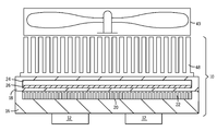
- FIG. 5 is a cross sectional view of a heatsink with external fins 48 and an external fan 49 , in accordance with certain embodiments.
- the heatsink 10 may conduct some heat through the top of the heat spreader 18 .
- the heatsink 10 may include external fins 48 .
- the external fins 48 may be air cooled via natural convection or forced convection via the fan 49 .
- the external fins 48 may be disposed on any of the illustrated embodiments.
- the external fins 48 may include parallel pin-type members, parallel plate-type members, diverging plate-type members, or any other suitable geometry or configuration.
- FIG. 6 is a block diagram of an exemplary power converter system 52 that employs an improved heatsink 10 , in accordance with certain embodiments.
- the power converter system 52 may include a rectifier circuitry 54 coupled to an alternating current (AC) power source 56 .
- the rectifier circuitry 54 receives AC power from the AC power source and generates a direct current (DC) voltage on the DC bus 58 .
- AC alternating current
- DC direct current
- An inverter circuitry 60 powered by the DC bus voltage, generates an output power waveform at a particular frequency.
- a typical inverter circuitry may include one or more insulated-gate, bipolar transistors (IGBTs) that are switched rapidly on and off to generate the output power waveform.
- the inverter circuitry 60 may be coupled to a control circuitry 62 that may receive a user input and provides drive signals that enable the IGBTs to generate the output waveform.
- the inverter circuitry 60 is driven using pulse width modulation. Rapid switching of the IGBTs may tend to generate substantial amounts of heat in the IGBT. The power handling capability of the IGBTs is often limited by the ability of the IGBTs to dissipate this heat. To keep the temperature of the inverter circuitry within an acceptable range, the inverter circuitry may be coupled to the improved heatsink 10 .
- the output power generated by the inverter circuitry 60 is then delivered to a load 66 .
- the load 66 may include a high power motor 68 that drives a compressor 70 coupled to a natural gas pipeline 72 .
- the motor 68 may drive a pump coupled to an oil pipeline.
- the motor 68 may provide the motive force for an electric vehicle, an electrical generator, industrial equipment, or any other device.
- the heatsink 10 may also be coupled to a wide variety of other components, such as computer processors, motherboards, batteries, power transmission devices, or any other component that may benefit from high levels of cooling.
- the improved heatsink 10 may be coupled to an electrical generator, such as a wind turbine, that provides power to an electrical distribution system.
- FIGS. 7-9 depict several exemplary heat spreaders 18 , in accordance with embodiments of the present invention.
- FIG. 7 depicts a heat sink 10 with a heat spreader 18 that includes a plurality of discrete, linear vapor chambers 24 (e.g., heat pipes).
- the vapor chambers 24 may be positioned in parallel rows and may be aligned with specific heat producing circuits 12 adjacent to the heat sink 10 . In other embodiments, the vapor chambers 24 may be positioned irrespective of the circuitry 12 .
- FIG. 8 depicts a heat sink 10 with a heat spreader 18 that includes a plurality of discrete, radial vapor chambers 24 .
- the vapor chambers 24 e.g., heat pipes
- the heat producing circuitry 12 may be located at the center of the heatsink 10 .
- the heat spreader 18 may include 2, 3, 4, 5, 6, 7, 8, 9, 10, or more diverging vapor chambers 24 .
- FIG. 9 depicts a heatsink 10 with a heat spreader 18 that includes a plurality of radial vapor chambers 24 that are joined at a central location 78 and radiate outward to the four corners 76 and four sides 80 of the heatsink 10 .
- Embodiments of the present invention may include many other heat spreader 18 configurations.
- a heat spreader in accordance with present embodiments may be round, triangular, V-shaped, or substantially any other shape as desirable to transfer heat away from heat producing circuitry.
- FIGS. 10-13 depict several alternative heatsinks 10 in accordance with embodiments of the present technique.
- FIG. 10 depicts an embodiment wherein the heatsink 10 includes a cooling plate 16 and a heat spreader 18 .
- the heat spreader 18 includes a plurality of cylindrical heat pipes 84 disposed between the fluid path 20 and the heat source, circuit 12 .
- the heat pipes 84 may include sealed cylindrical cavities with a wick 26 disposed on the inside surface of the cavity and a working fluid inside the cavity.
- the heat from the circuit 12 is first diffused laterally by the heat spreader 18 before passing into the fluid channel 20 .
- the fluid channel 20 is formed by machining the fins of the heat exchanger 22 directly in the fluid cooled plate 16 .
- FIG. 11 depicts an embodiment wherein the heatsink 10 includes a heat spreader 18 is disposed inside of and is surrounded by the fluid channel 20 .
- the heat spreader includes a flat rectangular vapor chamber 24 with wicks 26 disposed on the top and bottom surfaces of the cavity and filled with a working fluid.
- the fluid channel may include fins 22 , which may be bonded to the inside wall of the cooling plate 16 .
- the heat spreader 18 may be positioned within the fluid channel 20 by the fins 22 , or alternatively, the heat spreader 18 may be positioned using centering pins. In this embodiment, the heat spreader 18 diffuses heat more evenly throughout the fluid in the fluid channel 20 .
- FIG. 12 depicts an embodiment wherein the heatsink 10 includes a cooling plate 16 with one or more cylindrical fluid channels 20 and one or more cylindrical heat pipes 84 disposed inside of the fluid channels 20 .
- the fluid channels 20 may include fins 22 which increase the heat transfer from the fluid channel 20 to the cooling plate 16 .
- the fins 22 may also position the heat pipe 84 within the fluid channel 20 .
- the heat pipes 84 may also be held in place by centering pins.
- FIG. 13 depicts an embodiment wherein the heatsink includes a cooling plate 16 with one or more cylindrical heat pipes 84 and one or more cylindrical fluid channels 20 disposed inside of the heat pipes 84 .
- the fluid channels 20 may also be held in place by centering pins.
Abstract
Description
Claims (20)
Priority Applications (3)
| Application Number | Priority Date | Filing Date | Title |
|---|---|---|---|
| US12/324,757 US7796389B2 (en) | 2008-11-26 | 2008-11-26 | Method and apparatus for cooling electronics |
| EP09176384A EP2192827A3 (en) | 2008-11-26 | 2009-11-18 | Method And Apparatus For Cooling Electronics |
| JP2009264434A JP2010130011A (en) | 2008-11-26 | 2009-11-20 | Method and apparatus for cooling electronics |
Applications Claiming Priority (1)
| Application Number | Priority Date | Filing Date | Title |
|---|---|---|---|
| US12/324,757 US7796389B2 (en) | 2008-11-26 | 2008-11-26 | Method and apparatus for cooling electronics |
Publications (2)
| Publication Number | Publication Date |
|---|---|
| US20100128436A1 US20100128436A1 (en) | 2010-05-27 |
| US7796389B2 true US7796389B2 (en) | 2010-09-14 |
Family
ID=41737534
Family Applications (1)
| Application Number | Title | Priority Date | Filing Date |
|---|---|---|---|
| US12/324,757 Expired - Fee Related US7796389B2 (en) | 2008-11-26 | 2008-11-26 | Method and apparatus for cooling electronics |
Country Status (3)
| Country | Link |
|---|---|
| US (1) | US7796389B2 (en) |
| EP (1) | EP2192827A3 (en) |
| JP (1) | JP2010130011A (en) |
Cited By (47)
| Publication number | Priority date | Publication date | Assignee | Title |
|---|---|---|---|---|
| US20070283709A1 (en) * | 2006-06-09 | 2007-12-13 | Veeco Instruments Inc. | Apparatus and methods for managing the temperature of a substrate in a high vacuum processing system |
| US20100018678A1 (en) * | 2004-12-01 | 2010-01-28 | Convergence Technologies Limited | Vapor Chamber with Boiling-Enhanced Multi-Wick Structure |
| US20100287954A1 (en) * | 2009-03-25 | 2010-11-18 | Jayden Harman | Supersonic Cooling System |
| US20110027738A1 (en) * | 2009-07-30 | 2011-02-03 | Meyer Iv George Anthony | Supporting structure with height difference and vapor chamber having the supporting structure |
| US20110031919A1 (en) * | 2009-08-10 | 2011-02-10 | Emerson Climate Technologies, Inc. | Controller and method for minimizing phase advance current |
| US20110030390A1 (en) * | 2009-04-02 | 2011-02-10 | Serguei Charamko | Vortex Tube |
| US20110048062A1 (en) * | 2009-03-25 | 2011-03-03 | Thomas Gielda | Portable Cooling Unit |
| US20110048066A1 (en) * | 2009-03-25 | 2011-03-03 | Thomas Gielda | Battery Cooling |
| US20110051549A1 (en) * | 2009-07-25 | 2011-03-03 | Kristian Debus | Nucleation Ring for a Central Insert |
| US20110139405A1 (en) * | 2009-09-04 | 2011-06-16 | Jayden David Harman | System and method for heat transfer |
| US20110297347A1 (en) * | 2010-06-07 | 2011-12-08 | Liuzhou Wuling Motors Co., Ltd. | Heat dissipating system for electric vehicle drive controller |
| US20120090816A1 (en) * | 2010-10-13 | 2012-04-19 | William Marsh Rice University | Systems and methods for heat transfer utilizing heat exchangers with carbon nanotubes |
| US20120119498A1 (en) * | 2010-11-14 | 2012-05-17 | Jian-Yan Liu | Wind power generation device for electronic equipment |
| US20120120604A1 (en) * | 2010-11-11 | 2012-05-17 | Mingliang Hao | Heat dissipation device |
| US8295046B2 (en) | 2010-07-19 | 2012-10-23 | Hamilton Sundstrand Corporation | Non-circular radial heat sink |
| US8331091B2 (en) | 2010-09-01 | 2012-12-11 | Hamilton Sundstrand Corporation | Electronics package with radial heat sink and integrated blower |
| US20130027883A1 (en) * | 2011-07-25 | 2013-01-31 | International Business Machines Corporation | Flow boiling heat sink structure with vapor venting and condensing |
| US20140068942A1 (en) * | 2012-09-13 | 2014-03-13 | International Business Machines Corporation | Vapor condenser with three-dimensional folded structure |
| US20140084719A1 (en) * | 2011-02-10 | 2014-03-27 | Aisin Aw Co., Ltd. | Power control unit |
| US20140090815A1 (en) * | 2012-09-28 | 2014-04-03 | Alcatel-Lucent Usa Inc. | Cooling technique |
| US20140232219A1 (en) * | 2012-09-25 | 2014-08-21 | Debabrata Pal | Cooling arrangement for a motor assembly and method of cooling a motor assembly |
| US8820114B2 (en) | 2009-03-25 | 2014-09-02 | Pax Scientific, Inc. | Cooling of heat intensive systems |
| US8907716B2 (en) | 2012-12-28 | 2014-12-09 | General Electric Company | Systems and methods for control of power semiconductor devices |
| US20150062819A1 (en) * | 2013-08-29 | 2015-03-05 | Eaton Corporation | Apparatus and methods using heat pipes for linking electronic assemblies that unequally produce heat |
| US20150070841A1 (en) * | 2012-04-10 | 2015-03-12 | Ntn Corporation | Cooling structure for inverter device |
| US9061383B2 (en) | 2011-07-25 | 2015-06-23 | International Business Machines Corporation | Heat sink structure with a vapor-permeable membrane for two-phase cooling |
| US9069532B2 (en) | 2011-07-25 | 2015-06-30 | International Business Machines Corporation | Valve controlled, node-level vapor condensation for two-phase heat sink(s) |
| US9088232B2 (en) | 2009-08-10 | 2015-07-21 | Emerson Climate Technologies, Inc. | Power factor correction with variable bus voltage |
| US9154061B2 (en) | 2009-08-10 | 2015-10-06 | Emerson Climate Technologies, Inc. | Controller and method for transitioning between control angles |
| US20150330718A1 (en) * | 2013-08-28 | 2015-11-19 | Hamilton Sundstrand Corporation | Integrated blower diffuser-fin single phase heat exchanger |
| US9240749B2 (en) | 2012-08-10 | 2016-01-19 | Emerson Climate Technologies, Inc. | Motor drive control using pulse-width modulation pulse skipping |
| US20160330868A1 (en) * | 2015-05-05 | 2016-11-10 | Cooler Master Co., Ltd. | Cooling module, water-cooled cooling module and cooling system |
| US9504186B2 (en) | 2014-11-14 | 2016-11-22 | Caterpillar Inc. | Heatpipe imbedded coldplate enhancing IGBT heat spreading |
| US9634593B2 (en) | 2012-04-26 | 2017-04-25 | Emerson Climate Technologies, Inc. | System and method for permanent magnet motor control |
| US10032693B2 (en) | 2015-10-20 | 2018-07-24 | General Electric Company | Heat transfer chassis and method for forming the same |
| US10066876B2 (en) | 2016-09-09 | 2018-09-04 | Toyota Motor Engineering & Manufacturing North America, Inc. | Vapor chamber heat flux rectifier and thermal switch |
| US10345874B1 (en) * | 2016-05-02 | 2019-07-09 | Juniper Networks, Inc | Apparatus, system, and method for decreasing heat migration in ganged heatsinks |
| US10591964B1 (en) | 2017-02-14 | 2020-03-17 | Juniper Networks, Inc | Apparatus, system, and method for improved heat spreading in heatsinks |
| US20200100396A1 (en) * | 2018-09-24 | 2020-03-26 | Google Llc | Cooling electronic devices in a data center |
| US20210074605A1 (en) * | 2019-09-10 | 2021-03-11 | Aptiv Technologies Limited | Heat exchanger for electronics |
| US11044835B2 (en) * | 2019-03-27 | 2021-06-22 | Google Llc | Cooling electronic devices in a data center |
| US20220046824A1 (en) * | 2019-09-10 | 2022-02-10 | Furukawa Electric Co., Ltd. | Cooling device and cooling system using cooling device |
| US11324143B2 (en) * | 2019-12-30 | 2022-05-03 | GM Cruise Holdings, LLC | Embedded and immersed heat pipes in automated driving system computers |
| US11324144B2 (en) * | 2019-12-30 | 2022-05-03 | GM Cruise Holdings, LLC | Embedded and immersed vapor chambers in automated driving system computers |
| US11326836B1 (en) * | 2020-10-22 | 2022-05-10 | Asia Vital Components Co., Ltd. | Vapor/liquid condensation system |
| US11369042B2 (en) | 2019-04-10 | 2022-06-21 | Abb Schweiz Ag | Heat exchanger with integrated two-phase heat spreader |
| US11647612B2 (en) * | 2020-11-23 | 2023-05-09 | Toyota Motor Engineering & Manufacturing North America, Inc. | High-density integrated power electronic assembly including double-sided cooling structure |
Families Citing this family (38)
| Publication number | Priority date | Publication date | Assignee | Title |
|---|---|---|---|---|
| US8363418B2 (en) | 2011-04-18 | 2013-01-29 | Morgan/Weiss Technologies Inc. | Above motherboard interposer with peripheral circuits |
| JP5423998B2 (en) * | 2011-08-31 | 2014-02-19 | 株式会社安川電機 | Electronic component cooling unit and power conversion device |
| US20130206369A1 (en) * | 2012-02-13 | 2013-08-15 | Wei-I Lin | Heat dissipating device |
| DE202012008739U1 (en) * | 2012-09-12 | 2013-12-16 | Abb Technology Ag | Cooling circuit with sufficiently tight heat exchanger |
| EP2911193A4 (en) * | 2012-10-16 | 2016-06-15 | Fuji Electric Co Ltd | Cooling structure and heat generating body |
| TWM450828U (en) * | 2012-12-14 | 2013-04-11 | Litup Technology Co Ltd | LED module with separate heat-dissipation and electrical conduction paths, and related heat dissipation board |
| US9151546B2 (en) | 2013-02-28 | 2015-10-06 | General Electric Company | Heat exchanger assembly |
| US20140247560A1 (en) * | 2013-03-04 | 2014-09-04 | Rockwell Automation Technologies, Inc. | System and method to facilitate thermal transfer for motor drive features using diamond like carbon coating |
| CN105144861B (en) * | 2013-03-29 | 2018-04-17 | 慧与发展有限责任合伙企业 | Electronic device with cooling device |
| US9522837B2 (en) * | 2013-08-08 | 2016-12-20 | Corning Incorporated | Method of making glass articles |
| CN103415192B (en) * | 2013-08-20 | 2015-09-23 | 南京理工大学 | Vapor chamber heat pipe/microchannel cold plates composite construction temperature equalization system |
| CN103640494B (en) * | 2013-12-31 | 2015-10-21 | 重庆博耐特实业(集团)有限公司 | A kind of Large-power controller of electric car |
| US9532485B2 (en) * | 2014-02-21 | 2016-12-27 | Lenovo (Beijing) Co., Ltd. | Heat dissipating device and electronic apparatus |
| CN104812213A (en) * | 2015-04-01 | 2015-07-29 | 太仓陶氏电气有限公司 | Sealed type frequency transformer cooling device |
| CN208016185U (en) * | 2015-10-08 | 2018-10-26 | 古河电气工业株式会社 | Radiator |
| CN106444892B (en) * | 2016-09-12 | 2018-06-22 | 华东师范大学 | Temperature control system and optics console |
| KR102617349B1 (en) * | 2016-12-02 | 2023-12-26 | 삼성전자주식회사 | Printed circuit board, and solid state drive apparatus having the same |
| CN110024500B (en) * | 2017-02-03 | 2020-11-17 | 惠普发展公司,有限责任合伙企业 | Thermal management using steam and isolation chambers |
| US10622282B2 (en) * | 2017-07-28 | 2020-04-14 | Qualcomm Incorporated | Systems and methods for cooling an electronic device |
| CN109427708B (en) * | 2017-08-31 | 2022-12-13 | 比亚迪半导体股份有限公司 | Multichannel radiator and power module with same |
| DE102017215759A1 (en) * | 2017-09-07 | 2019-03-07 | Robert Bosch Gmbh | Cooling plate, as well as device with such a cooling plate |
| DE102017215952B3 (en) | 2017-09-11 | 2019-02-07 | F & S Prozessautomation GmbH | Heat sink with two hollow bodies and cooling arrangement |
| US10224264B1 (en) * | 2017-10-04 | 2019-03-05 | Qualcomm Incorporated | High performance evaporation-condensation thermal spreading chamber for compute packages |
| US10481651B2 (en) * | 2017-12-07 | 2019-11-19 | Toyota Motor Engineering & Manufacturing North America, Inc. | Integrated PCU and GPU cooling system |
| US10727160B2 (en) * | 2017-12-29 | 2020-07-28 | Intel Corporation | Thermal management component |
| US11145570B2 (en) * | 2017-12-29 | 2021-10-12 | Celestica Technology Consultancy (Shanghai) Co. Ltd | Closed loop liquid cooler and electronic device using the same |
| US10685900B2 (en) * | 2018-10-22 | 2020-06-16 | Deere & Company | Packaging of a semiconductor device with phase-change material for thermal performance |
| JP2020109781A (en) * | 2018-12-28 | 2020-07-16 | 日本電産株式会社 | Cooling apparatus |
| WO2020219022A1 (en) * | 2019-04-23 | 2020-10-29 | Hewlett-Packard Development Company, L.P. | Heat pipes for electronic devices |
| US10939592B2 (en) * | 2019-06-14 | 2021-03-02 | Intel Corporation | Liquid cooling system with sub atmospheric pressure coolant |
| US20200409398A1 (en) * | 2019-06-25 | 2020-12-31 | Intel Corporation | Device, system and method for providing microchannels with porous sidewall structures |
| CN110557931B (en) | 2019-08-30 | 2020-12-08 | 华为技术有限公司 | Vehicle-mounted device and vehicle |
| US11343945B2 (en) * | 2019-10-10 | 2022-05-24 | Cisco Technology, Inc. | Combined liquid and air cooling system for fail-safe operation of high power density ASIC devices |
| WO2021129692A1 (en) * | 2019-12-27 | 2021-07-01 | Intel Corporation | Cooling systems, cooling structures and electronic devices and methods for manufacturing or operating cooling systems, cooling structures and electronic devices |
| US20220392826A1 (en) * | 2021-06-08 | 2022-12-08 | Baidu Usa Llc | Component package for high power asic thermal management |
| FR3127631A1 (en) * | 2021-09-27 | 2023-03-31 | Valeo Systemes De Controle Moteur | Electronic assembly with an improved cooling element |
| EP4213185A1 (en) * | 2022-01-14 | 2023-07-19 | Siemens Aktiengesellschaft | Hybrid cooling body |
| WO2023158368A1 (en) * | 2022-02-18 | 2023-08-24 | Razer (Asia-Pacific) Pte. Ltd. | Vapor chamber |
Citations (24)
| Publication number | Priority date | Publication date | Assignee | Title |
|---|---|---|---|---|
| US4697205A (en) | 1986-03-13 | 1987-09-29 | Thermacore, Inc. | Heat pipe |
| US4833567A (en) | 1986-05-30 | 1989-05-23 | Digital Equipment Corporation | Integral heat pipe module |
| US4880052A (en) | 1989-02-27 | 1989-11-14 | Thermacore, Inc. | Heat pipe cooling plate |
| US6410982B1 (en) * | 1999-11-12 | 2002-06-25 | Intel Corporation | Heatpipesink having integrated heat pipe and heat sink |
| US20020144802A1 (en) * | 2001-04-06 | 2002-10-10 | Visteon Global Technologies | Evaporative cooling device and method |
| US6508301B2 (en) * | 2000-04-19 | 2003-01-21 | Thermal Form & Function | Cold plate utilizing fin with evaporating refrigerant |
| US20040055322A1 (en) * | 2002-09-19 | 2004-03-25 | Sun Microsystems, Inc. | Field replaceable packard refrigeration module with vapor chamber heat sink for cooling electronic components |
| US20040065111A1 (en) * | 2002-10-08 | 2004-04-08 | Sun Microsystems, Inc. | Field replaceable packaged refrigeration module with thermosyphon for cooling electronic components |
| US20040079100A1 (en) * | 2002-10-25 | 2004-04-29 | Sun Microsystems, Inc. | Field replaceable packaged refrigeration module with capillary pumped loop for cooling electronic components |
| US6808015B2 (en) * | 2000-03-24 | 2004-10-26 | Denso Corporation | Boiling cooler for cooling heating element by heat transfer with boiling |
| US6926072B2 (en) | 2003-10-22 | 2005-08-09 | Thermal Corp. | Hybrid loop heat pipe |
| US20050173096A1 (en) * | 2004-02-05 | 2005-08-11 | Wincomm Corporation | Heat dissipating device |
| US7077189B1 (en) * | 2005-01-21 | 2006-07-18 | Delphi Technologies, Inc. | Liquid cooled thermosiphon with flexible coolant tubes |
| US20060162903A1 (en) * | 2005-01-21 | 2006-07-27 | Bhatti Mohinder S | Liquid cooled thermosiphon with flexible partition |
| US20060162904A1 (en) * | 2005-01-21 | 2006-07-27 | Bhatti Mohinder S | Liquid cooled thermosiphon for electronic components |
| US20060185828A1 (en) * | 2003-07-22 | 2006-08-24 | Chikara Takehara | Thermosyphon device, cooling and heating device and method using the thermosyphone device, and plant cultivating method |
| US20070076376A1 (en) * | 2005-09-30 | 2007-04-05 | Intel Corporation | Method, apparatus and computer system for providing for the transfer of thermal energy |
| US7210304B2 (en) * | 2005-02-09 | 2007-05-01 | General Motors Corporation | Cooling arrangements for integrated electric motor-inverters |
| US20070204646A1 (en) * | 2006-03-01 | 2007-09-06 | Thomas Gagliano | Cold plate incorporating a heat pipe |
| US20080110594A1 (en) * | 2006-11-10 | 2008-05-15 | Martin Yves C | Air/fluid cooling system |
| US7450386B2 (en) * | 2005-07-30 | 2008-11-11 | Articchoke Enterprises Llc | Phase-separated evaporator, blade-thru condenser and heat dissipation system thereof |
| US7492594B2 (en) * | 2007-05-03 | 2009-02-17 | Hamilton Sundstrand Corporation | Electronic circuit modules cooling |
| US20090140417A1 (en) * | 2007-11-30 | 2009-06-04 | Gamal Refai-Ahmed | Holistic Thermal Management System for a Semiconductor Chip |
| US7604040B2 (en) * | 2005-06-15 | 2009-10-20 | Coolit Systems Inc. | Integrated liquid cooled heat sink for electronic components |
Family Cites Families (3)
| Publication number | Priority date | Publication date | Assignee | Title |
|---|---|---|---|---|
| JPS6338245A (en) * | 1986-08-01 | 1988-02-18 | Ishikawajima Harima Heavy Ind Co Ltd | Cold plate |
| JP2005079483A (en) * | 2003-09-03 | 2005-03-24 | Hitachi Ltd | Electronic apparatus |
| US20050083655A1 (en) * | 2003-10-15 | 2005-04-21 | Visteon Global Technologies, Inc. | Dielectric thermal stack for the cooling of high power electronics |
-
2008
- 2008-11-26 US US12/324,757 patent/US7796389B2/en not_active Expired - Fee Related
-
2009
- 2009-11-18 EP EP09176384A patent/EP2192827A3/en not_active Withdrawn
- 2009-11-20 JP JP2009264434A patent/JP2010130011A/en not_active Withdrawn
Patent Citations (27)
| Publication number | Priority date | Publication date | Assignee | Title |
|---|---|---|---|---|
| US4697205A (en) | 1986-03-13 | 1987-09-29 | Thermacore, Inc. | Heat pipe |
| US4833567A (en) | 1986-05-30 | 1989-05-23 | Digital Equipment Corporation | Integral heat pipe module |
| US4880052A (en) | 1989-02-27 | 1989-11-14 | Thermacore, Inc. | Heat pipe cooling plate |
| US6410982B1 (en) * | 1999-11-12 | 2002-06-25 | Intel Corporation | Heatpipesink having integrated heat pipe and heat sink |
| US6808015B2 (en) * | 2000-03-24 | 2004-10-26 | Denso Corporation | Boiling cooler for cooling heating element by heat transfer with boiling |
| US6508301B2 (en) * | 2000-04-19 | 2003-01-21 | Thermal Form & Function | Cold plate utilizing fin with evaporating refrigerant |
| US20020144802A1 (en) * | 2001-04-06 | 2002-10-10 | Visteon Global Technologies | Evaporative cooling device and method |
| US20040055322A1 (en) * | 2002-09-19 | 2004-03-25 | Sun Microsystems, Inc. | Field replaceable packard refrigeration module with vapor chamber heat sink for cooling electronic components |
| US20040065111A1 (en) * | 2002-10-08 | 2004-04-08 | Sun Microsystems, Inc. | Field replaceable packaged refrigeration module with thermosyphon for cooling electronic components |
| US20040079100A1 (en) * | 2002-10-25 | 2004-04-29 | Sun Microsystems, Inc. | Field replaceable packaged refrigeration module with capillary pumped loop for cooling electronic components |
| US20060185828A1 (en) * | 2003-07-22 | 2006-08-24 | Chikara Takehara | Thermosyphon device, cooling and heating device and method using the thermosyphone device, and plant cultivating method |
| US6926072B2 (en) | 2003-10-22 | 2005-08-09 | Thermal Corp. | Hybrid loop heat pipe |
| US7111394B2 (en) | 2003-10-22 | 2006-09-26 | Thermal Corp. | Hybrid loop heat pipe |
| US20050173096A1 (en) * | 2004-02-05 | 2005-08-11 | Wincomm Corporation | Heat dissipating device |
| US7077189B1 (en) * | 2005-01-21 | 2006-07-18 | Delphi Technologies, Inc. | Liquid cooled thermosiphon with flexible coolant tubes |
| US20060162904A1 (en) * | 2005-01-21 | 2006-07-27 | Bhatti Mohinder S | Liquid cooled thermosiphon for electronic components |
| US20060162903A1 (en) * | 2005-01-21 | 2006-07-27 | Bhatti Mohinder S | Liquid cooled thermosiphon with flexible partition |
| US20060162898A1 (en) * | 2005-01-21 | 2006-07-27 | Ilya Reyzin | Liquid cooled thermosiphon with flexible coolant tubes |
| US7506682B2 (en) * | 2005-01-21 | 2009-03-24 | Delphi Technologies, Inc. | Liquid cooled thermosiphon for electronic components |
| US7210304B2 (en) * | 2005-02-09 | 2007-05-01 | General Motors Corporation | Cooling arrangements for integrated electric motor-inverters |
| US7604040B2 (en) * | 2005-06-15 | 2009-10-20 | Coolit Systems Inc. | Integrated liquid cooled heat sink for electronic components |
| US7450386B2 (en) * | 2005-07-30 | 2008-11-11 | Articchoke Enterprises Llc | Phase-separated evaporator, blade-thru condenser and heat dissipation system thereof |
| US20070076376A1 (en) * | 2005-09-30 | 2007-04-05 | Intel Corporation | Method, apparatus and computer system for providing for the transfer of thermal energy |
| US20070204646A1 (en) * | 2006-03-01 | 2007-09-06 | Thomas Gagliano | Cold plate incorporating a heat pipe |
| US20080110594A1 (en) * | 2006-11-10 | 2008-05-15 | Martin Yves C | Air/fluid cooling system |
| US7492594B2 (en) * | 2007-05-03 | 2009-02-17 | Hamilton Sundstrand Corporation | Electronic circuit modules cooling |
| US20090140417A1 (en) * | 2007-11-30 | 2009-06-04 | Gamal Refai-Ahmed | Holistic Thermal Management System for a Semiconductor Chip |
Cited By (93)
| Publication number | Priority date | Publication date | Assignee | Title |
|---|---|---|---|---|
| US20100018678A1 (en) * | 2004-12-01 | 2010-01-28 | Convergence Technologies Limited | Vapor Chamber with Boiling-Enhanced Multi-Wick Structure |
| US20070283709A1 (en) * | 2006-06-09 | 2007-12-13 | Veeco Instruments Inc. | Apparatus and methods for managing the temperature of a substrate in a high vacuum processing system |
| US8333080B2 (en) | 2009-03-25 | 2012-12-18 | Pax Scientific, Inc. | Supersonic cooling system |
| US8820114B2 (en) | 2009-03-25 | 2014-09-02 | Pax Scientific, Inc. | Cooling of heat intensive systems |
| US20100287954A1 (en) * | 2009-03-25 | 2010-11-18 | Jayden Harman | Supersonic Cooling System |
| US8353168B2 (en) | 2009-03-25 | 2013-01-15 | Pax Scientific, Inc. | Thermodynamic cycle for cooling a working fluid |
| US20110048062A1 (en) * | 2009-03-25 | 2011-03-03 | Thomas Gielda | Portable Cooling Unit |
| US8353169B2 (en) | 2009-03-25 | 2013-01-15 | Pax Scientific, Inc. | Supersonic cooling system |
| US20110088419A1 (en) * | 2009-03-25 | 2011-04-21 | Jayden Harman | Thermodynamic Cycle for Cooling a Working Fluid |
| US20110088878A1 (en) * | 2009-03-25 | 2011-04-21 | Jayden Harman | Supersonic Cooling System |
| US8505322B2 (en) | 2009-03-25 | 2013-08-13 | Pax Scientific, Inc. | Battery cooling |
| US20110048066A1 (en) * | 2009-03-25 | 2011-03-03 | Thomas Gielda | Battery Cooling |
| US20110030390A1 (en) * | 2009-04-02 | 2011-02-10 | Serguei Charamko | Vortex Tube |
| US20110051549A1 (en) * | 2009-07-25 | 2011-03-03 | Kristian Debus | Nucleation Ring for a Central Insert |
| US20110027738A1 (en) * | 2009-07-30 | 2011-02-03 | Meyer Iv George Anthony | Supporting structure with height difference and vapor chamber having the supporting structure |
| US9564846B2 (en) | 2009-08-10 | 2017-02-07 | Emerson Climate Technologies, Inc. | Power factor correction with variable bus voltage |
| US8698433B2 (en) | 2009-08-10 | 2014-04-15 | Emerson Climate Technologies, Inc. | Controller and method for minimizing phase advance current |
| US20110031919A1 (en) * | 2009-08-10 | 2011-02-10 | Emerson Climate Technologies, Inc. | Controller and method for minimizing phase advance current |
| US9088232B2 (en) | 2009-08-10 | 2015-07-21 | Emerson Climate Technologies, Inc. | Power factor correction with variable bus voltage |
| US9154061B2 (en) | 2009-08-10 | 2015-10-06 | Emerson Climate Technologies, Inc. | Controller and method for transitioning between control angles |
| US9705433B2 (en) | 2009-08-10 | 2017-07-11 | Emerson Climate Technologies, Inc. | Controller and method for transitioning between control angles |
| US9912263B2 (en) | 2009-08-10 | 2018-03-06 | Emerson Climate Technologies, Inc. | Controller and method for transitioning between control angles |
| US8365540B2 (en) | 2009-09-04 | 2013-02-05 | Pax Scientific, Inc. | System and method for heat transfer |
| US8887525B2 (en) | 2009-09-04 | 2014-11-18 | Pax Scientific, Inc. | Heat exchange and cooling systems |
| US8359872B2 (en) | 2009-09-04 | 2013-01-29 | Pax Scientific, Inc. | Heating and cooling of working fluids |
| US20110139405A1 (en) * | 2009-09-04 | 2011-06-16 | Jayden David Harman | System and method for heat transfer |
| US8689915B2 (en) * | 2010-06-07 | 2014-04-08 | Liuzhou Wuling Motors Co., Ltd. | Heat dissipating system for electric vehicle drive controller |
| US20110297347A1 (en) * | 2010-06-07 | 2011-12-08 | Liuzhou Wuling Motors Co., Ltd. | Heat dissipating system for electric vehicle drive controller |
| US8295046B2 (en) | 2010-07-19 | 2012-10-23 | Hamilton Sundstrand Corporation | Non-circular radial heat sink |
| US8331091B2 (en) | 2010-09-01 | 2012-12-11 | Hamilton Sundstrand Corporation | Electronics package with radial heat sink and integrated blower |
| US20120090816A1 (en) * | 2010-10-13 | 2012-04-19 | William Marsh Rice University | Systems and methods for heat transfer utilizing heat exchangers with carbon nanotubes |
| US8737071B2 (en) * | 2010-11-11 | 2014-05-27 | Huawei Technologies Co., Ltd. | Heat dissipation device |
| US20120120604A1 (en) * | 2010-11-11 | 2012-05-17 | Mingliang Hao | Heat dissipation device |
| US20120119498A1 (en) * | 2010-11-14 | 2012-05-17 | Jian-Yan Liu | Wind power generation device for electronic equipment |
| US8421264B2 (en) * | 2010-11-14 | 2013-04-16 | Asia Vital Components Co., Ltd. | Wind power generation device for electronic equipment |
| US20140084719A1 (en) * | 2011-02-10 | 2014-03-27 | Aisin Aw Co., Ltd. | Power control unit |
| US8875825B2 (en) * | 2011-02-10 | 2014-11-04 | Toyota Jidosha Kabushiki Kaisha | Power control unit |
| US9078379B2 (en) | 2011-07-25 | 2015-07-07 | International Business Machines Corporation | Flow boiling heat sink with vapor venting and condensing |
| US9687943B2 (en) | 2011-07-25 | 2017-06-27 | International Business Machines Corporation | Heat sink structure with a vapor-permeable membrane for two-phase cooling |
| US20130027883A1 (en) * | 2011-07-25 | 2013-01-31 | International Business Machines Corporation | Flow boiling heat sink structure with vapor venting and condensing |
| US8564952B2 (en) * | 2011-07-25 | 2013-10-22 | International Business Machines Corporation | Flow boiling heat sink structure with vapor venting and condensing |
| US9446487B2 (en) | 2011-07-25 | 2016-09-20 | International Business Machines Corporation | Heat sink structure with a vapor-permeable membrane for two-phase cooling |
| US9061383B2 (en) | 2011-07-25 | 2015-06-23 | International Business Machines Corporation | Heat sink structure with a vapor-permeable membrane for two-phase cooling |
| US9061382B2 (en) | 2011-07-25 | 2015-06-23 | International Business Machines Corporation | Heat sink structure with a vapor-permeable membrane for two-phase cooling |
| US9067288B2 (en) | 2011-07-25 | 2015-06-30 | International Business Machines Corporation | Heat sink structure with a vapor-permeable membrane for two-phase cooling |
| US9069532B2 (en) | 2011-07-25 | 2015-06-30 | International Business Machines Corporation | Valve controlled, node-level vapor condensation for two-phase heat sink(s) |
| US9201474B2 (en) | 2011-07-25 | 2015-12-01 | International Business Machines Corporation | Valve controlled, node-level vapor condensation for two-phase heat sink(s) |
| US9075582B2 (en) | 2011-07-25 | 2015-07-07 | International Business Machines Corporation | Valve controlled, node-level vapor condensation for two-phase heat sink(s) |
| US9623520B2 (en) | 2011-07-25 | 2017-04-18 | International Business Machines Corporation | Heat sink structure with a vapor-permeable membrane for two-phase cooling |
| US9089936B2 (en) | 2011-07-25 | 2015-07-28 | International Business Machines Corporation | Heat sink structure with a vapor-permeable membrane for two-phase cooling |
| US9102021B2 (en) | 2011-07-25 | 2015-08-11 | International Business Machines Corporation | Heat sink structure with a vapor-permeable membrane for two-phase cooling |
| US9113581B2 (en) | 2011-07-25 | 2015-08-18 | International Business Machines Corporation | Valve controlled, node-level vapor condensation for two-phase heat sink(s) |
| US20150070841A1 (en) * | 2012-04-10 | 2015-03-12 | Ntn Corporation | Cooling structure for inverter device |
| US9402336B2 (en) * | 2012-04-10 | 2016-07-26 | Ntn Corporation | Cooling structure for inverter device |
| US9634593B2 (en) | 2012-04-26 | 2017-04-25 | Emerson Climate Technologies, Inc. | System and method for permanent magnet motor control |
| US10075116B2 (en) | 2012-04-26 | 2018-09-11 | Emerson Climate Technologies, Inc. | System and method for permanent magnet motor control |
| US9991834B2 (en) | 2012-04-26 | 2018-06-05 | Emerson Climate Technologies, Inc. | System and method for permanent magnet motor control |
| US9853588B2 (en) | 2012-08-10 | 2017-12-26 | Emerson Climate Technologies, Inc. | Motor drive control using pulse-width modulation pulse skipping |
| US9240749B2 (en) | 2012-08-10 | 2016-01-19 | Emerson Climate Technologies, Inc. | Motor drive control using pulse-width modulation pulse skipping |
| US8739406B2 (en) * | 2012-09-13 | 2014-06-03 | International Business Machines Corporation | Vapor condenser with three-dimensional folded structure |
| US20140068942A1 (en) * | 2012-09-13 | 2014-03-13 | International Business Machines Corporation | Vapor condenser with three-dimensional folded structure |
| US8941994B2 (en) | 2012-09-13 | 2015-01-27 | International Business Machines Corporation | Vapor condenser with three-dimensional folded structure |
| US9178400B2 (en) * | 2012-09-25 | 2015-11-03 | Hamilton Sundstrand Corporation | Cooling arrangement for a motor assembly and method of cooling a motor assembly |
| US20140232219A1 (en) * | 2012-09-25 | 2014-08-21 | Debabrata Pal | Cooling arrangement for a motor assembly and method of cooling a motor assembly |
| US20140090815A1 (en) * | 2012-09-28 | 2014-04-03 | Alcatel-Lucent Usa Inc. | Cooling technique |
| US9557118B2 (en) * | 2012-09-28 | 2017-01-31 | LGS Innovations LLC | Cooling technique |
| US8907716B2 (en) | 2012-12-28 | 2014-12-09 | General Electric Company | Systems and methods for control of power semiconductor devices |
| US20150330718A1 (en) * | 2013-08-28 | 2015-11-19 | Hamilton Sundstrand Corporation | Integrated blower diffuser-fin single phase heat exchanger |
| US20150062819A1 (en) * | 2013-08-29 | 2015-03-05 | Eaton Corporation | Apparatus and methods using heat pipes for linking electronic assemblies that unequally produce heat |
| US9398723B2 (en) * | 2013-08-29 | 2016-07-19 | Eaton Corporation | Apparatus and methods using heat pipes for linking electronic assemblies that unequally produce heat |
| US9504186B2 (en) | 2014-11-14 | 2016-11-22 | Caterpillar Inc. | Heatpipe imbedded coldplate enhancing IGBT heat spreading |
| US20160330868A1 (en) * | 2015-05-05 | 2016-11-10 | Cooler Master Co., Ltd. | Cooling module, water-cooled cooling module and cooling system |
| US10410954B2 (en) * | 2015-05-05 | 2019-09-10 | Cooler Master Co., Ltd. | Cooling module, water-cooled cooling module and cooling system |
| US10032693B2 (en) | 2015-10-20 | 2018-07-24 | General Electric Company | Heat transfer chassis and method for forming the same |
| US10345874B1 (en) * | 2016-05-02 | 2019-07-09 | Juniper Networks, Inc | Apparatus, system, and method for decreasing heat migration in ganged heatsinks |
| US10066876B2 (en) | 2016-09-09 | 2018-09-04 | Toyota Motor Engineering & Manufacturing North America, Inc. | Vapor chamber heat flux rectifier and thermal switch |
| US10591964B1 (en) | 2017-02-14 | 2020-03-17 | Juniper Networks, Inc | Apparatus, system, and method for improved heat spreading in heatsinks |
| US10966352B2 (en) * | 2018-09-24 | 2021-03-30 | Google Llc | Cooling electronic devices in a data center |
| CN112740841A (en) * | 2018-09-24 | 2021-04-30 | 谷歌有限责任公司 | Cooling electronic equipment in a data center |
| CN112740841B (en) * | 2018-09-24 | 2023-09-05 | 谷歌有限责任公司 | Server tray package, method of forming the same, and method for cooling heat generating equipment in a data center |
| US20200100396A1 (en) * | 2018-09-24 | 2020-03-26 | Google Llc | Cooling electronic devices in a data center |
| US11044835B2 (en) * | 2019-03-27 | 2021-06-22 | Google Llc | Cooling electronic devices in a data center |
| US11369042B2 (en) | 2019-04-10 | 2022-06-21 | Abb Schweiz Ag | Heat exchanger with integrated two-phase heat spreader |
| US20210074605A1 (en) * | 2019-09-10 | 2021-03-11 | Aptiv Technologies Limited | Heat exchanger for electronics |
| US11217505B2 (en) * | 2019-09-10 | 2022-01-04 | Aptiv Technologies Limited | Heat exchanger for electronics |
| US20220046824A1 (en) * | 2019-09-10 | 2022-02-10 | Furukawa Electric Co., Ltd. | Cooling device and cooling system using cooling device |
| US11324144B2 (en) * | 2019-12-30 | 2022-05-03 | GM Cruise Holdings, LLC | Embedded and immersed vapor chambers in automated driving system computers |
| US11737244B2 (en) | 2019-12-30 | 2023-08-22 | Gm Cruise Holdings Llc | Embedded and immersed heat pipes in automated driving system computers |
| US11324143B2 (en) * | 2019-12-30 | 2022-05-03 | GM Cruise Holdings, LLC | Embedded and immersed heat pipes in automated driving system computers |
| US11326836B1 (en) * | 2020-10-22 | 2022-05-10 | Asia Vital Components Co., Ltd. | Vapor/liquid condensation system |
| US20220196328A1 (en) * | 2020-10-22 | 2022-06-23 | Asia Vital Components Co., Ltd. | Vapor/liquid condensation system |
| US11555653B2 (en) * | 2020-10-22 | 2023-01-17 | Asia Vital Components Co. Ltd. | Vapor/liquid condensation system |
| US11647612B2 (en) * | 2020-11-23 | 2023-05-09 | Toyota Motor Engineering & Manufacturing North America, Inc. | High-density integrated power electronic assembly including double-sided cooling structure |
Also Published As
| Publication number | Publication date |
|---|---|
| JP2010130011A (en) | 2010-06-10 |
| EP2192827A3 (en) | 2012-02-29 |
| EP2192827A2 (en) | 2010-06-02 |
| US20100128436A1 (en) | 2010-05-27 |
Similar Documents
| Publication | Publication Date | Title |
|---|---|---|
| US7796389B2 (en) | Method and apparatus for cooling electronics | |
| US6988535B2 (en) | Channeled flat plate fin heat exchange system, device and method | |
| Jörg et al. | Direct single impinging jet cooling of a MOSFET power electronic module | |
| US5020586A (en) | Air-cooled heat exchanger for electronic circuit modules | |
| US8833435B2 (en) | Microscale cooling apparatus and method | |
| US20120087088A1 (en) | Microscale heat transfer systems | |
| US7106589B2 (en) | Heat sink, assembly, and method of making | |
| TWM512883U (en) | Heat dissipation module, water-cooling heat dissipation module and heat dissipation system | |
| KR20110036018A (en) | Semiconductor device | |
| Blinov et al. | Cooling Methods for High-Power Electronic Systems. | |
| CN110557927A (en) | Heat sink and method of manufacturing a heat sink | |
| JP2008227150A (en) | Electronic apparatus | |
| CN116324671A (en) | Cooling device for cooling components of a circuit board | |
| JP2013098468A (en) | Power semiconductor module cooling apparatus | |
| US7468885B2 (en) | Cooling device for interface card | |
| JP5057838B2 (en) | Power semiconductor element cooling device | |
| US11876036B2 (en) | Fluid cooling system including embedded channels and cold plates | |
| CN112399778A (en) | Combined heat dissipation device for multiple high-power chips | |
| WO2024066705A1 (en) | Heat dissipation system and power apparatus | |
| US20050135061A1 (en) | Heat sink, assembly, and method of making | |
| CN210014476U (en) | Radiator, air condensing units and air conditioner | |
| WO2010099545A1 (en) | Microscale heat transfer systems | |
| JP3093441B2 (en) | Heat sink for high power electronic equipment | |
| JP2011096983A (en) | Cooling device | |
| TWI530249B (en) | Hybrid heat sink assembly |
Legal Events
| Date | Code | Title | Description |
|---|---|---|---|
| AS | Assignment |
Owner name: GENERAL ELECTRIC COMPANY, NEW YORK Free format text: ASSIGNMENT OF ASSIGNORS INTEREST;ASSIGNORS:EDMUNDS, HOWARD ROSS;MCFALLS, RICHARD KENNETH;REEL/FRAME:021905/0733 Effective date: 20081120 |
|
| FEPP | Fee payment procedure |
Free format text: PAYOR NUMBER ASSIGNED (ORIGINAL EVENT CODE: ASPN); ENTITY STATUS OF PATENT OWNER: LARGE ENTITY |
|
| STCF | Information on status: patent grant |
Free format text: PATENTED CASE |
|
| FPAY | Fee payment |
Year of fee payment: 4 |
|
| MAFP | Maintenance fee payment |
Free format text: PAYMENT OF MAINTENANCE FEE, 8TH YEAR, LARGE ENTITY (ORIGINAL EVENT CODE: M1552) Year of fee payment: 8 |
|
| FEPP | Fee payment procedure |
Free format text: MAINTENANCE FEE REMINDER MAILED (ORIGINAL EVENT CODE: REM.); ENTITY STATUS OF PATENT OWNER: LARGE ENTITY |
|
| LAPS | Lapse for failure to pay maintenance fees |
Free format text: PATENT EXPIRED FOR FAILURE TO PAY MAINTENANCE FEES (ORIGINAL EVENT CODE: EXP.); ENTITY STATUS OF PATENT OWNER: LARGE ENTITY |
|
| STCH | Information on status: patent discontinuation |
Free format text: PATENT EXPIRED DUE TO NONPAYMENT OF MAINTENANCE FEES UNDER 37 CFR 1.362 |
|
| FP | Lapsed due to failure to pay maintenance fee |
Effective date: 20220914 |